JP2014019900A - Plating device and substrate holder cleaning method - Google Patents

Plating device and substrate holder cleaning method Download PDF

Info

Publication number
JP2014019900A
JP2014019900A JP2012159205A JP2012159205A JP2014019900A JP 2014019900 A JP2014019900 A JP 2014019900A JP 2012159205 A JP2012159205 A JP 2012159205A JP 2012159205 A JP2012159205 A JP 2012159205A JP 2014019900 A JP2014019900 A JP 2014019900A
Authority
JP
Japan
Prior art keywords
substrate
substrate holder
plating
cleaning
holder
Prior art date
Legal status (The legal status is an assumption and is not a legal conclusion. Google has not performed a legal analysis and makes no representation as to the accuracy of the status listed.)
Granted
Application number
JP2012159205A
Other languages
Japanese (ja)
Other versions
JP6022836B2 (en
Inventor
Junpei Fujikata
淳平 藤方
Tadashi Shimoyama
正 下山
Current Assignee (The listed assignees may be inaccurate. Google has not performed a legal analysis and makes no representation or warranty as to the accuracy of the list.)
Ebara Corp
Original Assignee
Ebara Corp
Priority date (The priority date is an assumption and is not a legal conclusion. Google has not performed a legal analysis and makes no representation as to the accuracy of the date listed.)
Filing date
Publication date
Application filed by Ebara Corp filed Critical Ebara Corp
Priority to JP2012159205A priority Critical patent/JP6022836B2/en
Priority to TW102124885A priority patent/TWI577839B/en
Priority to KR1020130082777A priority patent/KR101930965B1/en
Priority to US13/943,984 priority patent/US9376760B2/en
Priority to CN201310304043.4A priority patent/CN103572356B/en
Publication of JP2014019900A publication Critical patent/JP2014019900A/en
Priority to US15/163,588 priority patent/US10119198B2/en
Application granted granted Critical
Publication of JP6022836B2 publication Critical patent/JP6022836B2/en
Active legal-status Critical Current
Anticipated expiration legal-status Critical

Links

Images

Classifications

    • CCHEMISTRY; METALLURGY
    • C25ELECTROLYTIC OR ELECTROPHORETIC PROCESSES; APPARATUS THEREFOR
    • C25DPROCESSES FOR THE ELECTROLYTIC OR ELECTROPHORETIC PRODUCTION OF COATINGS; ELECTROFORMING; APPARATUS THEREFOR
    • C25D17/00Constructional parts, or assemblies thereof, of cells for electrolytic coating
    • BPERFORMING OPERATIONS; TRANSPORTING
    • B08CLEANING
    • B08BCLEANING IN GENERAL; PREVENTION OF FOULING IN GENERAL
    • B08B3/00Cleaning by methods involving the use or presence of liquid or steam
    • B08B3/04Cleaning involving contact with liquid
    • B08B3/08Cleaning involving contact with liquid the liquid having chemical or dissolving effect
    • CCHEMISTRY; METALLURGY
    • C25ELECTROLYTIC OR ELECTROPHORETIC PROCESSES; APPARATUS THEREFOR
    • C25DPROCESSES FOR THE ELECTROLYTIC OR ELECTROPHORETIC PRODUCTION OF COATINGS; ELECTROFORMING; APPARATUS THEREFOR
    • C25D17/00Constructional parts, or assemblies thereof, of cells for electrolytic coating
    • C25D17/06Suspending or supporting devices for articles to be coated
    • CCHEMISTRY; METALLURGY
    • C25ELECTROLYTIC OR ELECTROPHORETIC PROCESSES; APPARATUS THEREFOR
    • C25DPROCESSES FOR THE ELECTROLYTIC OR ELECTROPHORETIC PRODUCTION OF COATINGS; ELECTROFORMING; APPARATUS THEREFOR
    • C25D21/00Processes for servicing or operating cells for electrolytic coating
    • C25D21/08Rinsing
    • CCHEMISTRY; METALLURGY
    • C25ELECTROLYTIC OR ELECTROPHORETIC PROCESSES; APPARATUS THEREFOR
    • C25DPROCESSES FOR THE ELECTROLYTIC OR ELECTROPHORETIC PRODUCTION OF COATINGS; ELECTROFORMING; APPARATUS THEREFOR
    • C25D17/00Constructional parts, or assemblies thereof, of cells for electrolytic coating
    • C25D17/001Apparatus specially adapted for electrolytic coating of wafers, e.g. semiconductors or solar cells
    • CCHEMISTRY; METALLURGY
    • C25ELECTROLYTIC OR ELECTROPHORETIC PROCESSES; APPARATUS THEREFOR
    • C25DPROCESSES FOR THE ELECTROLYTIC OR ELECTROPHORETIC PRODUCTION OF COATINGS; ELECTROFORMING; APPARATUS THEREFOR
    • C25D5/00Electroplating characterised by the process; Pretreatment or after-treatment of workpieces
    • C25D5/10Electroplating with more than one layer of the same or of different metals
    • C25D5/12Electroplating with more than one layer of the same or of different metals at least one layer being of nickel or chromium

Landscapes

  • Chemical & Material Sciences (AREA)
  • Chemical Kinetics & Catalysis (AREA)
  • Engineering & Computer Science (AREA)
  • Electrochemistry (AREA)
  • Materials Engineering (AREA)
  • Metallurgy (AREA)
  • Organic Chemistry (AREA)
  • General Chemical & Material Sciences (AREA)
  • Electroplating Methods And Accessories (AREA)
  • Container, Conveyance, Adherence, Positioning, Of Wafer (AREA)

Abstract

PROBLEM TO BE SOLVED: To clean a substrate with a cleaning fluid without removing the substrate holder from a plating device, further, without wetting an electrical contact provided in the substrate holder, while driving the plating device.SOLUTION: The plating device comprises: a plating tank of holding a plating liquid at the inside; a substrate carrying apparatus of discharging a substrate before plating from a substrate cassette mounted on the device and returning the substrate after plating to the substrate cassette; a substrate holder 18 of sealing the outer circumferential part of the surface of the substrate discharged from the substrate cassette with a sealing member and dipping the same into the plating liquid in the plating tank while detachably holding the substrate; a dummy substrate DW arranged at a position in which the substrate carrying apparatus can access; and substrate holder cleaning tanks 26a, 26b of feeding the cleaning liquid to the inside, sealing the outer circumferential part of the surface of the dummy substrate with the sealing member, dipping the substrate holder freely detachably holding the dummy substrate and performing cleaning.

Description

本発明は、めっき装置及び基板ホルダ洗浄方法に関し、特に半導体ウェーハ等の基板を基板ホルダで保持しつつめっき液中に浸漬させて基板表面に接続用バンプや配線等を形成するディップ式のめっき装置、及び該めっき装置に使用される基板ホルダの洗浄方法に関する。   The present invention relates to a plating apparatus and a substrate holder cleaning method, and more particularly, a dip type plating apparatus that forms a connection bump, wiring, or the like on a substrate surface by immersing it in a plating solution while holding the substrate such as a semiconductor wafer by the substrate holder. And a method for cleaning a substrate holder used in the plating apparatus.

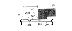
半導体ウェーハ等の基板表面の所定位置に接続用バンプを電気めっきで形成する場合には、図1及び図2に示すように、表面に給電層としてのシード層200を形成し、このシード層200の表面にレジスト202を塗布した後、レジスト202の所定位置に開口部202aを設けた基板Wを用意し、基板Wの表面外周部を基板ホルダに取付けたシール部材204でシールし、このシール部材204で囲まれためっき領域Aをめっき液に接触させることが広く行われている。これにより、めっき領域Aの内部のレジスト開口部202a内に位置して外部に露出したシード層200の表面にバンプに使用される金属206がめっきにより形成される。   When the connection bump is formed by electroplating at a predetermined position on the surface of the substrate such as a semiconductor wafer, a seed layer 200 as a power feeding layer is formed on the surface as shown in FIGS. After the resist 202 is applied to the surface of the substrate, a substrate W having an opening 202a at a predetermined position of the resist 202 is prepared, and the outer peripheral portion of the surface of the substrate W is sealed with a seal member 204 attached to a substrate holder. It is widely performed that the plating region A surrounded by 204 is brought into contact with a plating solution. As a result, the metal 206 used for the bump is formed by plating on the surface of the seed layer 200 located in the resist opening 202a inside the plating region A and exposed to the outside.

このように、基板Wの表面外周部を基板ホルダに取付けたシール部材204でシールする時、このシール部材204が基板Wの外周部に位置するレジスト開口部202aの表面を跨る場合がある。このことは、基板Wの表面の有効領域をできるだけ広く確保する上で一般に避けられない。そして、この表面をシール部材204が跨っているレジスト開口部202a内に金属206が形成される時に、金属206がレジスト202の上面まで達するような異常な析出が起こして、シール部材204に金属207が付着する場合がある。このシール部材204に付着した金属207は、基板Wをめっきする度に成長する。   As described above, when the outer peripheral portion of the surface of the substrate W is sealed by the seal member 204 attached to the substrate holder, the seal member 204 may straddle the surface of the resist opening 202a located at the outer peripheral portion of the substrate W. This is generally unavoidable in securing as large an effective area as possible on the surface of the substrate W. Then, when the metal 206 is formed in the resist opening 202a over which the seal member 204 is straddling the surface, abnormal precipitation occurs so that the metal 206 reaches the upper surface of the resist 202, and the metal 207 is formed on the seal member 204. May adhere. The metal 207 adhered to the seal member 204 grows every time the substrate W is plated.

このようにシール部材204に金属207が付着したまま基板ホルダを使用し続けると、基板表面に形成される金属の膜厚不足や面内均一性の悪化を引き起こし、また、シール部材204で囲まれためっき領域Aをめっき液に浸漬させた時にめっき液のリークを引き起こす一因になる。このため、基板ホルダを定期的、或いは必要に応じて随時洗浄して、シール部材204に付着した金属207を除去する必要がある。   If the substrate holder is continuously used while the metal 207 is attached to the seal member 204 in this manner, the metal film formed on the substrate surface will be insufficient in film thickness and in-plane uniformity will be deteriorated, and will be surrounded by the seal member 204. This causes a leakage of the plating solution when the plating region A is immersed in the plating solution. Therefore, it is necessary to remove the metal 207 adhering to the seal member 204 by cleaning the substrate holder periodically or as needed.

また、基板Wの表面にレジストが無い基板をめっきする時は、シード層200とシール部材204が直接接触するため、シール部材204に異常析出した金属207が付着する場合がある。   Further, when plating a substrate having no resist on the surface of the substrate W, the seed layer 200 and the seal member 204 are in direct contact with each other, so that the abnormally deposited metal 207 may adhere to the seal member 204.

このため、基板ホルダのメンテナンス時に、手動、または金属207を溶解させる洗浄液(薬液)で洗浄が行われる。一般に、基板ホルダのメンテナンスは、めっき装置より基板ホルダを取出し、基板ホルダの洗浄と定期交換部品の交換が行われる。   For this reason, at the time of maintenance of the substrate holder, cleaning is performed manually or with a cleaning solution (chemical solution) that dissolves the metal 207. In general, the maintenance of the substrate holder is performed by removing the substrate holder from the plating apparatus, cleaning the substrate holder, and replacing the periodic replacement parts.

洗浄装置として、搬送手段により搬送される吊治具の移動空間に、脱膜液槽、水槽、酸洗槽等を順に配置して、吊治具を自動的に洗浄するようにしたもの(特許文献1参照)や、薬液への浸漬方式に代えて、洗浄液を噴射する噴射方式を採用して用具を洗浄ようにしたもの(特許文献2参照)が提案されている。また、ワークを保持したパレットを、水洗部を通過させた後、プール内に浸漬させてストックすることで、ワークの乾燥や酸化を防止するようにしたワーク搬送システム(特許文献3参照)や、基板を保持した保持部を処理槽から退避させ、保持部を処理面とともに洗浄するようにした液処理装置(特許文献4参照)が提案されている。   As a cleaning device, a membrane removal liquid tank, a water tank, a pickling tank, etc. are sequentially arranged in the moving space of the hanging jig conveyed by the conveying means so that the hanging jig is automatically washed (patent) Document 1) and an apparatus in which a tool is cleaned by using a spraying method of spraying a cleaning liquid instead of a chemical immersion method (see Patent Document 2) have been proposed. In addition, after passing the pallet holding the workpiece through the water-washing section, it is immersed in the pool and stocked to prevent the workpiece from drying and oxidizing (see Patent Document 3), There has been proposed a liquid processing apparatus (see Patent Document 4) in which a holding unit holding a substrate is retracted from a processing tank and the holding unit is cleaned together with a processing surface.

出願人は、めっき装置の内部に、基板を保持することなく開放させた状態で基板ホルダを洗浄する基板ホルダ洗浄部を備えることで、基板ホルダをめっき装置から取出すことなく、めっき装置内で自動的に洗浄するようにしためっき装置を提案している(特許文献5参照)。   The applicant automatically installs the substrate holder inside the plating apparatus without removing the substrate holder from the plating apparatus by providing a substrate holder cleaning unit for cleaning the substrate holder in an open state without holding the substrate. The plating apparatus which was made to wash automatically is proposed (refer patent document 5).

実開昭58−92374号公報Japanese Utility Model Publication No. 58-92374 実開昭61−159083号公報Japanese Utility Model Publication No. 61-159083 特開昭63−166990号公報JP-A 63-166990 特開2002−249896号公報JP 2002-249896 A 特開2008−45179号公報JP 2008-45179 A

めっき装置から基板ホルダを取出して洗浄するためには、めっき装置を停止させる必要がある。代替の基板ホルダがあったとしても、少なくとも基板ホルダの入れ替えを行う間は、めっき装置を停止させる必要がある。しかも、基板ホルダのめっき装置からの取出しには多くの人手がかかる。そのため、めっき装置の生産性が悪化する。   In order to remove and clean the substrate holder from the plating apparatus, it is necessary to stop the plating apparatus. Even if there is an alternative substrate holder, it is necessary to stop the plating apparatus at least during replacement of the substrate holder. Moreover, it takes a lot of manpower to remove the substrate holder from the plating apparatus. Therefore, the productivity of the plating apparatus is deteriorated.

特許文献1〜4に記載の発明は、基板を着脱自在に保持する基板ホルダを、めっき装置から取出すことなく、めっき装置の内部に保管した状態で、自動的に洗浄するようにしたものではない。   The inventions described in Patent Documents 1 to 4 do not automatically wash the substrate holder that holds the substrate detachably without removing it from the plating apparatus and stored in the plating apparatus. .

特許文献5に記載の発明のように、基板を保持することなく開放させた状態で基板ホルダを洗浄すると、めっき中にシール部材でシールされ、基板のシード層に接触して給電する電気接点が洗浄液で濡れてしまう。濡れた電気接点が基板のシード層に接触すると、電気接点との接触部でシード層が溶出し、電気接点とシード層との導通性が悪化してしまう。このため、電気接点は、乾燥状態にある必要があり、電気接点が濡れていると、電気接点が乾燥するまでの間、その基板ホルダは使用することができない。しかも、基板ホルダの内部に位置する電気接点を短時間に乾燥させることは一般にかなり困難である。   As in the invention described in Patent Document 5, when the substrate holder is cleaned in an open state without holding the substrate, an electrical contact that is sealed with a sealing member during plating and contacts the seed layer of the substrate to supply power is provided. It gets wet with the cleaning solution. When the wet electrical contact comes into contact with the seed layer of the substrate, the seed layer is eluted at the contact portion with the electrical contact, and the electrical conductivity between the electrical contact and the seed layer is deteriorated. For this reason, the electrical contact needs to be in a dry state. If the electrical contact is wet, the substrate holder cannot be used until the electrical contact is dried. Moreover, it is generally quite difficult to dry the electrical contacts located inside the substrate holder in a short time.

基板ホルダで基板を保持しながら、基板表面に多層複合めっきを行うようにしためっき装置の場合、基板ホルダのシール部材には複数の種類の金属207(図2参照)が付着する。これらの複数の種類の金属207を効率的に溶解させて洗浄する洗浄液は同一でない場合が多く、複数の種類の洗浄液で基板ホルダを洗浄する必要がある。しかし、基板ホルダのシール部材に異常析出した複数の種類の金属に応じて、複数の洗浄槽をめっき装置内に設置すると、めっき装置のフットプリントがかなり大きくなる。   In the case of a plating apparatus in which multilayer composite plating is performed on the substrate surface while holding the substrate with the substrate holder, a plurality of types of metals 207 (see FIG. 2) adhere to the sealing member of the substrate holder. In many cases, the cleaning liquid for efficiently dissolving and cleaning the plurality of types of metal 207 is not the same, and it is necessary to clean the substrate holder with the plurality of types of cleaning liquid. However, if a plurality of cleaning tanks are installed in the plating apparatus according to a plurality of types of metals that are abnormally deposited on the sealing member of the substrate holder, the footprint of the plating apparatus becomes considerably large.

本発明は上記事情に鑑みて為されたもので、基板ホルダをめっき装置から取出すことなく、しかも基板ホルダに備えられている電気接点を洗浄液で濡らすことなく、めっき装置を運転させたまま、基板ホルダを洗浄液で洗浄できるようにしためっき装置及び該基板ホルダの洗浄方法を提供することを目的とする。   The present invention has been made in view of the above circumstances, and without removing the substrate holder from the plating apparatus, and without wetting the electrical contacts provided on the substrate holder with the cleaning liquid, while the plating apparatus is operated, It is an object of the present invention to provide a plating apparatus capable of cleaning a holder with a cleaning liquid and a method for cleaning the substrate holder.

本発明のめっき装置は、めっき液を内部に保持するめっき槽と、装置に搭載された基板カセットからめっき前の基板を取出し、めっき後の基板を基板カセットに戻す基板搬送装置と、前記基板搬送装置によって前記基板カセットから取出された基板の被めっき面の外周部をシール部材でシールして該基板を着脱自在に保持し前記めっき槽内のめっき液に浸漬させる基板ホルダと、前記基板搬送装置がアクセス可能な位置に配置されるダミー基板と、内部に洗浄液を供給し、前記ダミー基板の表面の外周部をシール部材でシールして該ダミー基板を着脱自在に保持した基板ホルダを前記洗浄液に浸漬して洗浄するための基板ホルダ洗浄槽とを有する。   The plating apparatus of the present invention includes a plating tank that holds a plating solution therein, a substrate transfer device that takes out a substrate before plating from a substrate cassette mounted on the apparatus, and returns the substrate after plating to the substrate cassette, and the substrate transfer A substrate holder for sealing an outer peripheral portion of a surface to be plated taken out from the substrate cassette by an apparatus with a sealing member, detachably holding the substrate, and dipping in a plating solution in the plating tank; and the substrate transfer device A substrate that holds the dummy substrate detachably by sealing the outer periphery of the surface of the dummy substrate with a sealing member. A substrate holder cleaning tank for immersion and cleaning.

このように、基板ホルダを洗浄槽内に供給され洗浄液で洗浄することで、基板ホルダをめっき装置から取出すことなく、めっき装置を運転させたまま、基板ホルダのシール部材に付着した金属を洗浄することができる。しかも、ダミー基板の表面の外周部をシール部材でシールし、ダミー基板を保持した状態で基板ホルダを洗浄することで、基板ホルダに備えられている電気接点が洗浄液で濡れることを防止しつつ、基板ホルダの洗浄液による洗浄を行うことができる。   In this way, the substrate holder is supplied into the cleaning tank and cleaned with the cleaning liquid, so that the metal attached to the sealing member of the substrate holder is cleaned while the plating apparatus is operated without taking out the substrate holder from the plating apparatus. be able to. Moreover, by sealing the outer periphery of the surface of the dummy substrate with a sealing member and cleaning the substrate holder while holding the dummy substrate, while preventing the electrical contacts provided on the substrate holder from getting wet with the cleaning liquid, The substrate holder can be cleaned with the cleaning liquid.

本発明に好ましい一態様において、前記基板ホルダ洗浄槽は、複数種類の洗浄液とリンス液が個別に供給できるように構成されている。   In a preferred aspect of the present invention, the substrate holder cleaning tank is configured so that a plurality of types of cleaning liquids and rinsing liquids can be supplied individually.

これにより、基板ホルダのシール部材に複数の種類の金属が付着する時に、例えば第1洗浄液を基板ホルダ洗浄槽の内部に供給して基板ホルダを第1洗浄液で洗浄し、リンス液で基板ホルダをリンスした後、第2洗浄液を基板ホルダ洗浄槽の内部に供給して基板ホルダを第2洗浄液で洗浄し、リンス液で基板ホルダをリンスする工程を繰り返すことで、めっき装置のフットプリントを増大させることなく、シール部材に付着した複数の種類の金属を効率的に溶解させ、除去することができる。   Accordingly, when a plurality of types of metals adhere to the sealing member of the substrate holder, for example, the first cleaning liquid is supplied to the inside of the substrate holder cleaning tank, the substrate holder is cleaned with the first cleaning liquid, and the substrate holder is cleaned with the rinsing liquid. After rinsing, the second cleaning liquid is supplied into the substrate holder cleaning tank, the substrate holder is cleaned with the second cleaning liquid, and the process of rinsing the substrate holder with the rinsing liquid is repeated to increase the footprint of the plating apparatus. Therefore, a plurality of types of metals adhering to the seal member can be efficiently dissolved and removed.

本発明に好ましい一態様において、前記基板ホルダ洗浄槽は、基板ホルダを保管するストッカを兼用している。
これにより、基板ホルダ洗浄槽を備えることで、めっき装置のフットプリントが増大するのを防止することができる。
In a preferred aspect of the present invention, the substrate holder cleaning tank also serves as a stocker for storing the substrate holder.
Thereby, it can prevent that the footprint of a plating apparatus increases by providing a substrate holder cleaning tank.

本発明の好ましい一態様において、めっき装置は、複数の基板ホルダを内部に備え、一部の基板ホルダを使用してめっきを行いながら、他の基板ホルダを前記基板ホルダ洗浄槽で洗浄する。   In a preferred aspect of the present invention, the plating apparatus includes a plurality of substrate holders inside, and while performing plating using some of the substrate holders, the other substrate holders are cleaned in the substrate holder cleaning tank.

本発明に好ましい一態様において、前記ダミー基板は、装置に搭載される基板カセット内に収納されて前記基板搬送装置がアクセス可能な位置に配置される。
これにより、ダミー基板をめっき装置の内部に配置することなく、基板ホルダの洗浄が必要になったときに、ダミー基板をめっき装置内の処置位置に配置することができる。
In a preferred aspect of the present invention, the dummy substrate is housed in a substrate cassette mounted on the apparatus and disposed at a position accessible by the substrate transfer apparatus.
Thus, when the substrate holder needs to be cleaned without arranging the dummy substrate inside the plating apparatus, the dummy substrate can be arranged at the treatment position in the plating apparatus.

本発明の基板ホルダ洗浄方法は、ダミー基板の表面外周部をシール部材でシールして該ダミー基板を着脱自在に保持した基板ホルダを基板ホルダ洗浄槽内に吊下げ保持し、前記基板ホルダ洗浄槽の内部に洗浄液を供給し該洗浄液中に基板ホルダを浸漬させて基板ホルダを洗浄する。   In the substrate holder cleaning method of the present invention, the outer peripheral portion of the dummy substrate is sealed with a sealing member, and the substrate holder holding the dummy substrate in a detachable manner is suspended and held in the substrate holder cleaning tank. The substrate holder is cleaned by supplying a cleaning solution into the substrate and immersing the substrate holder in the cleaning solution.

本発明の好ましい一態様において、前記基板ホルダ洗浄槽の内部に複数の洗浄液及びリンス液を個別に供給して基板ホルダを複数の洗浄液で個別に洗浄する。   In a preferred aspect of the present invention, a plurality of cleaning liquids and a rinsing liquid are individually supplied into the substrate holder cleaning tank, and the substrate holder is individually cleaned with the plurality of cleaning liquids.

本発明によれば、基板ホルダをめっき装置から取出すことなく、めっき装置を運転させたまま、基板ホルダを該基板ホルダに備えられている電気接点が洗浄液で濡れることを防止しつつ洗浄液で洗浄することができ、めっき装置のスループットが低下するのを防止することができる。   According to the present invention, without removing the substrate holder from the plating apparatus, the substrate holder is cleaned with the cleaning liquid while the plating apparatus is in operation, while preventing the electrical contacts provided on the substrate holder from getting wet with the cleaning liquid. It is possible to prevent the throughput of the plating apparatus from decreasing.

めっき時に基板の表面外周部をシールする基板ホルダのシール部材と基板との関係の要部を示す平面図である。It is a top view which shows the principal part of the relationship between the sealing member of the board | substrate holder which seals the outer peripheral part of the surface of a board | substrate at the time of metal plating, and a board | substrate. 基板の表面外周部を基板ホルダのシール部材でシールしてめっきを行っている時の状態の要部を示す断面図である。It is sectional drawing which shows the principal part of a state when plating by sealing the surface outer peripheral part of a board | substrate with the sealing member of a board | substrate holder. 本発明の実施形態のめっき装置の全体配置図である。1 is an overall layout diagram of a plating apparatus according to an embodiment of the present invention. 図3に示す基板ホルダの概略を示す斜視図である。It is a perspective view which shows the outline of the substrate holder shown in FIG. 図3に示す基板ホルダの平面図である。It is a top view of the substrate holder shown in FIG. 図3に示す基板ホルダの右側面図である。FIG. 4 is a right side view of the substrate holder shown in FIG. 3. 図6のA部拡大図である。It is the A section enlarged view of FIG. 図3に示すめっき装置に備えられている基板ホルダ洗浄槽の概要図である。It is a schematic diagram of the substrate holder washing tank with which the plating apparatus shown in FIG. 3 is equipped. 他の基板ホルダ洗浄槽を示す概要図である。It is a schematic diagram which shows another substrate holder washing tank.

以下、本発明の実施形態を図面を参照して説明する。以下の例では、半導体ウェーハ等の基板表面に、Cuめっき、Niめっき及びSnAg合金めっきを順次行って、半導体ウェーハ等の基板表面の所定箇所に、Cu−Ni−SnAg合金からなるバンプを形成するようにしている。なお、めっきに使用される金属は、上記に限定されないことは勿論である。   Hereinafter, embodiments of the present invention will be described with reference to the drawings. In the following example, Cu plating, Ni plating, and SnAg alloy plating are sequentially performed on a substrate surface such as a semiconductor wafer, and bumps made of Cu—Ni—SnAg alloy are formed at predetermined locations on the substrate surface such as a semiconductor wafer. I am doing so. Of course, the metal used for plating is not limited to the above.

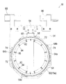
図3は、本発明の実施形態のめっき装置の全体配置図を示す。図3に示すように、このめっき装置には、半導体ウェーハ等の基板Wを収納した基板カセット10を搭載する2台のカセットテーブル12と、基板Wのオリフラやノッチなどの位置を所定の方向に合わせるアライナ14と、めっき処理後の基板Wを高速回転させて乾燥させるスピンドライヤ16が備えられている。更に、この近くには、基板ホルダ18を載置して基板Wの該基板ホルダ18への着脱を行う基板着脱部20が設けられ、これらのユニットの中央には、これらの間で基板Wを搬送する搬送用ロボットからかる基板搬送装置22が配置されている。   FIG. 3 shows an overall layout of the plating apparatus according to the embodiment of the present invention. As shown in FIG. 3, this plating apparatus includes two cassette tables 12 on which a substrate cassette 10 containing a substrate W such as a semiconductor wafer is mounted, and positions of orientation flats, notches, etc. of the substrate W in a predetermined direction. An aligner 14 to be combined and a spin dryer 16 that rotates the substrate W after the plating process at high speed to dry the substrate W are provided. In addition, a substrate attaching / detaching portion 20 for placing the substrate holder 18 and attaching / detaching the substrate W to / from the substrate holder 18 is provided in the vicinity of the substrate holder 18. A substrate transfer device 22 is disposed from a transfer robot for transfer.

更に、基板搬送装置22に近接した位置に、内部にダミー基板DWを収納したダミー基板カセット24が配置され、基板搬送装置22は、ダミー基板カセット24の内部に収納したダミー基板DWにアクセスできるようになっている。ダミー基板DWは、基板Wと同じ形状の、例えばパターンが形成されていないベアシリコンあるいは表面にシリコン酸化層が形成されたシリコン酸化膜基板からなり、基板Wと同様に、基板着脱部20で基板ホルダ18への着脱が行われる。ダミー基板DWの数は、一度に洗浄する基板ホルダ18の数を超えている。   Further, a dummy substrate cassette 24 in which a dummy substrate DW is accommodated is disposed at a position close to the substrate conveyance device 22 so that the substrate conveyance device 22 can access the dummy substrate DW accommodated in the dummy substrate cassette 24. It has become. The dummy substrate DW is composed of bare silicon having the same shape as the substrate W, for example, a bare silicon having no pattern formed thereon or a silicon oxide film substrate having a silicon oxide layer formed on the surface thereof. Attachment / detachment to / from the holder 18 is performed. The number of dummy substrates DW exceeds the number of substrate holders 18 to be cleaned at a time.

そして、基板着脱部20側から順に、基板ホルダ18の保管及び一時仮置きを行うストッカを兼ねる第1基板ホルダ洗浄槽26a及び第2基板ホルダ洗浄槽26b、基板を純水に浸漬させて濡らすことで表面の親水性を良くするプリウェット槽28、基板の表面にめっき前処理を行う前処理槽30、基板及び基板ホルダ18に付着した前処理液を洗浄する前処理液水洗槽32、内部にCuめっき液を入れ電気めっきを行って基板表面にCu膜を形成するCuめっき槽34a、基板及び基板ホルダ18に付着したCuめっき液を洗浄する第1水洗槽36a、内部にNiめっき液を入れ電気めっきを行って基板表面に形成されたCu膜の表面にNi膜を形成するNiめっき槽34b、基板及び基板ホルダ18に付着したNiめっき液を洗浄する第2水洗槽36b、基板表面を純水で水洗し水切り(ブロー処理)を行うブロー槽38、基板及び基板ホルダ18に付着したSnAg合金めっき液を洗浄する第3水洗槽36c、及び内部にSnAg合金めっき液を入れ電気めっきを行って基板表面に形成されたNi膜の表面にSnAg合金膜を形成するSnAg合金めっき槽34cが順に配置されている。   Then, in order from the substrate attaching / detaching unit 20 side, the first substrate holder cleaning tank 26a and the second substrate holder cleaning tank 26b, which also serve as stockers for storing and temporarily placing the substrate holder 18, and the substrate are immersed in pure water to be wetted. In the pre-wetting bath 28 for improving the hydrophilicity of the surface, a pre-treatment bath 30 for performing pre-plating treatment on the surface of the substrate, a pre-treatment liquid washing bath 32 for washing the pre-treatment liquid adhering to the substrate and the substrate holder 18, A Cu plating solution 34a for forming a Cu film on the surface of the substrate by introducing a Cu plating solution, a first washing bath 36a for cleaning the Cu plating solution adhering to the substrate and the substrate holder 18, and a Ni plating solution inside A Ni plating bath 34b for forming a Ni film on the surface of the Cu film formed on the surface of the substrate by electroplating, and a Ni plating solution adhering to the substrate and the substrate holder 18 are washed. A washing tank 36b, a blow tank 38 for washing the substrate surface with pure water and draining (blow processing), a third washing tank 36c for washing the SnAg alloy plating solution adhering to the substrate and the substrate holder 18, and a SnAg alloy plating inside An SnAg alloy plating tank 34c for forming a SnAg alloy film on the surface of the Ni film formed on the surface of the substrate by introducing the liquid and performing electroplating is sequentially arranged.

前処理槽30内には、シール部材に付着した金属207(図2参照)を溶解することができる洗浄液が供給される。洗浄液としては、例えば銅を溶解させるには硫酸と過酸化水素水との水溶液、Niを溶解させるためには水酸化ナトリウム水溶液、SnAg合金を溶解させるには30〜50wt%の硝酸の水溶液またはメタンスルホン酸からなる水溶液が使用される。前処理液水洗槽32には、洗浄後の基板を保持した基板ホルダ18を引き上げながら基板ホルダ18に向けて空気を吹付けることで、基板及び基板ホルダ18に付着した純水を除去するためのブロー機構が備えられている。この例では、多数のSnAg合金めっき槽34cを備えることで、稼働率を向上させるようにしている。   A cleaning liquid capable of dissolving the metal 207 (see FIG. 2) attached to the seal member is supplied into the pretreatment tank 30. Examples of the cleaning liquid include an aqueous solution of sulfuric acid and hydrogen peroxide solution for dissolving copper, an aqueous sodium hydroxide solution for dissolving Ni, an aqueous solution of 30-50 wt% nitric acid or methane for dissolving SnAg alloy. An aqueous solution consisting of sulfonic acid is used. The pretreatment liquid water washing tank 32 is for removing pure water adhering to the substrate and the substrate holder 18 by blowing air toward the substrate holder 18 while pulling up the substrate holder 18 holding the cleaned substrate. A blow mechanism is provided. In this example, the availability factor is improved by providing a large number of SnAg alloy plating tanks 34c.

更に、これらの各機器の側方に位置して、これらの各機器の間で基板ホルダ18を基板とともに搬送する、例えばリニアモータ方式を採用した基板ホルダ搬送装置40が備えられている。この基板ホルダ搬送装置40は、基板着脱部20と基板ホルダ洗浄槽26a,26bとの間で基板を搬送する第1トランスポータ42と、基板ホルダ洗浄槽26a,26b、プリウェット槽28、前処理槽30、水洗槽32,36a,36b,36c、めっき槽34a,34b,34c及びブロー槽38との間で基板を搬送する第2トランスポータ44を有している。なお、第2トランスポータ44を備えることなく、第1トランスポータ42のみを備えるようにしてもよい。   Furthermore, a substrate holder transport device 40 that employs, for example, a linear motor system is provided that is located on the side of each device and transports the substrate holder 18 together with the substrate between these devices. The substrate holder transport apparatus 40 includes a first transporter 42 that transports a substrate between the substrate attaching / detaching unit 20 and the substrate holder cleaning tanks 26a and 26b, a substrate holder cleaning tank 26a and 26b, a pre-wet tank 28, and a pretreatment. A second transporter 44 is provided for transporting the substrate among the tank 30, the washing tanks 32, 36a, 36b, and 36c, the plating tanks 34a, 34b, and 34c, and the blow tank 38. Note that only the first transporter 42 may be provided without providing the second transporter 44.

また、この基板ホルダ搬送装置40の各めっき槽34a,34b,34cを挟んだ反対側には、各めっき槽34a,34b,34cの内部に位置してめっき液を攪拌する掻き混ぜ棒としてのパドル(図示せず)を駆動するパドル駆動装置46が配置されている。   Further, on the opposite side of the plating holders 34a, 34b, and 34c of the substrate holder transport device 40, a paddle as a stirring rod that is located inside the plating tanks 34a, 34b, and 34c and stirs the plating solution. A paddle driving device 46 for driving (not shown) is arranged.

基板着脱部20は、レール50に沿って横方向にスライド自在な平板状の載置プレート52を備えており、この載置プレート52に2個の基板ホルダ18を水平状態で並列に載置して、この一方の基板ホルダ18と基板搬送装置22との間で基板Wの受渡しを行った後、載置プレート52を横方向にスライドさせて、他方の基板ホルダ18と基板搬送装置22との間で基板Wの受渡しを行うようになっている。   The board attaching / detaching unit 20 includes a flat plate-like mounting plate 52 that is slidable in the lateral direction along the rail 50. Two board holders 18 are placed in parallel on the mounting plate 52 in a horizontal state. Then, after delivering the substrate W between the one substrate holder 18 and the substrate transport device 22, the mounting plate 52 is slid in the lateral direction, and the other substrate holder 18 and the substrate transport device 22 The substrate W is delivered between them.

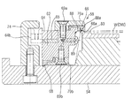
基板ホルダ18は、図4乃至図7に示すように、例えば塩化ビニル製で矩形平板状の第1保持部材(固定保持部材)54と、この第1保持部材54にヒンジ56を介して開閉自在に取付けた第2保持部材(可動保持部材)58とを有している。なお、この例では、第2保持部材58を、ヒンジ56を介して開閉自在に構成した例を示しているが、例えば第2保持部材58を第1保持部材54に対峙した位置に配置し、この第2保持部材58を第1保持部材54に向けて前進させて開閉するようにしてもよい。   As shown in FIGS. 4 to 7, the substrate holder 18 is openable and closable via a first holding member (fixed holding member) 54 made of, for example, vinyl chloride and having a rectangular flat plate shape, and a hinge 56. And a second holding member (movable holding member) 58 attached thereto. In this example, the second holding member 58 is configured to be openable and closable via the hinge 56. However, for example, the second holding member 58 is disposed at a position facing the first holding member 54. The second holding member 58 may be advanced toward the first holding member 54 to open and close.

第2保持部材58は、基部60とリング状のシールホルダ62とを有し、例えば塩化ビニル製で、下記の押えリング64との滑りを良くしている。シールホルダ62の第1保持部材54と対向する面には、基板ホルダ18で基板Wを保持した時、基板Wの表面外周部に圧接してここをシールする基板側(内側)シール部材66が内方に突出して取付けられている。更に、シールホルダ62の第1保持部材54と対向する面には、基板側シール部材66の外方位置で第1保持部材54に圧接してここをシールするホルダ側(外側)シール部材68が取付けられている。   The second holding member 58 includes a base portion 60 and a ring-shaped seal holder 62, and is made of, for example, vinyl chloride to improve sliding with the presser ring 64 described below. On the surface of the seal holder 62 facing the first holding member 54, when the substrate W is held by the substrate holder 18, there is a substrate side (inner side) seal member 66 that presses and seals the outer peripheral portion of the surface of the substrate W. It is mounted inwardly protruding. Further, on the surface of the seal holder 62 facing the first holding member 54, there is a holder side (outside) seal member 68 that presses against and seals the first holding member 54 at an outer position of the substrate side sealing member 66. Installed.

図7に示すように、基板側シール部材66は、シールホルダ62と、該シールホルダ62にボルト等の締結具69aを介して取付けられる第1固定リング70aとの間に挟持されてシールホルダ62に取付けられ、ホルダ側シール部材68は、シールホルダ62と、該シールホルダ62にボルト等の締結具69bを介して取付けられる第2固定リング70bとの間に挟持されてシールホルダ62に取付けられている。   As shown in FIG. 7, the board-side seal member 66 is sandwiched between a seal holder 62 and a first fixing ring 70 a attached to the seal holder 62 via a fastener 69 a such as a bolt. The holder side seal member 68 is sandwiched between the seal holder 62 and a second fixing ring 70b attached to the seal holder 62 via a fastener 69b such as a bolt, and is attached to the seal holder 62. ing.

第2保持部材58のシールホルダ62の外周部には、段部が設けられ、この段部に、押えリング64がスペーサ65を介して回転自在に装着されている。なお、押えリング64は、シールホルダ62の側面に外方に突出ように取付けられた押え板72(図5参照)により、脱出不能に装着されている。この押えリング64は、酸に対して耐食性に優れ、十分な剛性を有する、例えばチタンから構成され、スペーサ65は、押えリング64がスムーズに回転できるように、摩擦係数の低い材料、例えばPTEFで構成されている。   A step portion is provided on the outer peripheral portion of the seal holder 62 of the second holding member 58, and a presser ring 64 is rotatably attached to the step portion via a spacer 65. The presser ring 64 is mounted so as not to escape by a presser plate 72 (see FIG. 5) attached to the side surface of the seal holder 62 so as to protrude outward. The presser ring 64 is made of, for example, titanium having excellent corrosion resistance against acid and sufficient rigidity, and the spacer 65 is made of a material having a low friction coefficient, such as PTEF, so that the presser ring 64 can smoothly rotate. It is configured.

押えリング64の外側方に位置して、第1保持部材54には、内方に突出する突出部を有する逆L字状のクランパ74が円周方向に沿って等間隔で立設されている。一方、押えリング64の円周方向に沿ったクランパ74と対向する位置には、外方に突出する突起部64bが設けられている。そして、クランパ74の内方突出部の下面及び押えリング64の突起部64aの上面は、回転方向に沿って互いに逆方向に傾斜するテーパ面となっている。押えリング64の円周方向に沿った複数箇所(例えば4箇所)には、上方に突出するポッチ64aが設けられている。これにより、回転ピン(図示せず)を回転させてポッチ64aを横から押し回すことにより、押えリング64を回転させることができる。   Located on the outer side of the presser ring 64, the first holding member 54 is provided with inverted L-shaped clampers 74 having protrusions protruding inward at equal intervals along the circumferential direction. . On the other hand, a projecting portion 64 b that protrudes outward is provided at a position facing the clamper 74 along the circumferential direction of the presser ring 64. The lower surface of the inwardly projecting portion of the clamper 74 and the upper surface of the protruding portion 64a of the presser ring 64 are tapered surfaces that are inclined in opposite directions along the rotational direction. At a plurality of locations (for example, 4 locations) along the circumferential direction of the presser ring 64, potches 64a projecting upward are provided. Thereby, the presser ring 64 can be rotated by rotating a rotary pin (not shown) and pushing the potch 64a from the side.

これにより、第2保持部材58を開いた状態で、第1保持部材54の中央部に基板Wを挿入し、ヒンジ56を介して第2保持部材58を閉じ、押えリング64を時計回りに回転させて、押えリング64の突起部64bをクランパ74の内方突出部の内部に滑り込ませることで、押えリング64とクランパ74にそれそれぞれ設けたテーパ面を介して、第1保持部材54と第2保持部材58とを互いに締付けてロックし、押えリング64を反時計回りに回転させて逆L字状のクランパ74の押えリング64の突起部64bから引抜くことで、このロックを解くようになっている。そして、このようにして第2保持部材58をロックした時、基板側シール部材66の内周面側の下方突出部下端が基板ホルダ18で保持した基板Wの表面外周部に、ホルダ側シール部材68にあっては、その外周側の下方突出部下端が第1保持部材54の表面にそれぞれ圧接し、シール部材66,68を均一に押圧して、ここをシールする。   Thus, with the second holding member 58 open, the substrate W is inserted into the center of the first holding member 54, the second holding member 58 is closed via the hinge 56, and the presser ring 64 is rotated clockwise. Then, the protrusion 64b of the presser ring 64 is slid into the inner projecting part of the clamper 74, whereby the first holding member 54 and the first holding member 54 are connected to each other through the tapered surfaces provided on the presser ring 64 and the clamper 74, respectively. The two holding members 58 are tightened and locked together, and the presser ring 64 is rotated counterclockwise and pulled out from the protrusion 64b of the presser ring 64 of the reverse L-shaped clamper 74 so that the lock is released. It has become. Then, when the second holding member 58 is locked in this way, the lower end of the lower protruding portion on the inner peripheral surface side of the substrate side sealing member 66 is placed on the outer peripheral portion of the surface of the substrate W held by the substrate holder 18. In 68, the lower end of the lower projecting portion on the outer peripheral side is in pressure contact with the surface of the first holding member 54, and the seal members 66 and 68 are pressed uniformly to seal them.

ダミー基板DWにあっても同様に、第2保持部材58を開いた状態で、第1保持部材54の中央部にダミー基板DWを挿入し、ヒンジ56を介して第2保持部材58を閉じた後、押えリング64を時計回りに回転させて、第2保持部材58をロックし、押えリング64を反時計回りに回転させて逆L字状のクランパ74の押えリング64の突起部64bから引抜くことで、このロックを解くようになっている。第2保持部材58をロックした時、基板側シール部材66の内周面側の下方突出部下端が基板ホルダ18で保持したダミー基板DWの表面外周部に、ホルダ側シール部材68にあっては、その外周側の下方突出部下端が第1保持部材54の表面にそれぞれ圧接し、シール部材66,68を均一に押圧して、ここをシールする。   Similarly, in the dummy substrate DW, the dummy substrate DW is inserted into the central portion of the first holding member 54 with the second holding member 58 opened, and the second holding member 58 is closed via the hinge 56. Thereafter, the presser ring 64 is rotated clockwise to lock the second holding member 58, and the presser ring 64 is rotated counterclockwise to be pulled from the protrusion 64 b of the presser ring 64 of the inverted L-shaped clamper 74. By unplugging, this lock is released. When the second holding member 58 is locked, the holder-side seal member 68 has the lower end of the downward projecting portion on the inner peripheral surface side of the substrate-side seal member 66 on the outer peripheral portion of the surface of the dummy substrate DW held by the substrate holder 18. The lower end of the lower projecting portion on the outer peripheral side comes into pressure contact with the surface of the first holding member 54 and presses the seal members 66 and 68 uniformly to seal them.

第1保持部材54の周縁部には、基板Wの大きさに合わせてリング状に突出し、表面が基板Wの周縁部に当接して該基板Wを支持する支持面80となる突条部82が設けられており、この突条部82の円周方向に沿った所定位置に凹部84が設けられている。   The first holding member 54 protrudes in a ring shape in accordance with the size of the substrate W, and has a ridge 82 serving as a support surface 80 that supports the substrate W by contacting the periphery of the substrate W. A recess 84 is provided at a predetermined position along the circumferential direction of the protrusion 82.

そして、図5に示すように、この各凹部84内に、ハンド90に設けた外部接点から延びる複数の配線にそれぞれ接続した複数(図示では12個)の導電体(電気接点)86が配置されて、第1保持部材54の支持面80上に基板Wを載置した際、この導電体86の端部が基板Wの側方で第1保持部材54の表面にばね性を有した状態で露出して、図7に示す電気接点88の下部に接触するようになっている。   As shown in FIG. 5, a plurality (12 in the figure) of conductors (electrical contacts) 86 respectively connected to a plurality of wirings extending from external contacts provided in the hand 90 are disposed in the respective recesses 84. When the substrate W is placed on the support surface 80 of the first holding member 54, the end portion of the conductor 86 has a spring property on the surface of the first holding member 54 on the side of the substrate W. It is exposed to come into contact with the lower part of the electrical contact 88 shown in FIG.

導電体86に電気的に接続される電気接点88は、ボルト等の締結具89を介して第2保持部材58のシールホルダ62に固着されている。この電気接点88は、板ばね形状に形成され、基板側シール部材66の外方に位置して、内方に板ばね状に突出する接点部を有しており、この接点部において、その弾性力によるばね性を有して容易に屈曲し、しかも第1保持部材54と第2保持部材58で基板Wを保持した時に、電気接点88の接点部が、第1保持部材54の支持面80上に支持された基板Wの外周面に弾性的に接触するように構成されている。   An electrical contact 88 electrically connected to the conductor 86 is fixed to the seal holder 62 of the second holding member 58 via a fastener 89 such as a bolt. The electrical contact 88 is formed in the shape of a leaf spring, and has a contact portion that is located outside the board-side seal member 66 and projects inwardly in the shape of a leaf spring. When the substrate W is held by the first holding member 54 and the second holding member 58, the contact portion of the electrical contact 88 is supported by the support surface 80 of the first holding member 54. It is comprised so that it may contact elastically with the outer peripheral surface of the board | substrate W supported on the top.

第2保持部材58の開閉は、図示しないシリンダと第2保持部材58の自重によって行われる。つまり、第1保持部材54には通孔54aが設けられ、載置プレート52の上に基板ホルダ18を載置した時に該通孔54aに対向する位置にシリンダが設けられている。これにより、シリンダロッドを伸展させ、通孔54aを通じて押圧棒で第2保持部材58のシールホルダ62を上方に押上げることで第2保持部材58を開き、シリンダロッドを収縮させることで、第2保持部材58をその自重で閉じるようになっている。   The second holding member 58 is opened and closed by the weight of a cylinder (not shown) and the second holding member 58. In other words, the first holding member 54 is provided with a through hole 54 a, and a cylinder is provided at a position facing the through hole 54 a when the substrate holder 18 is placed on the placement plate 52. As a result, the cylinder rod is extended, the second holding member 58 is opened by pushing the seal holder 62 of the second holding member 58 upward with the pressing rod through the through hole 54a, and the cylinder rod is contracted, so that the second The holding member 58 is closed by its own weight.

基板ホルダ18の第1保持部材54の端部には、基板ホルダ18を搬送したり、吊下げ支持したりする際の支持部となる一対の略T字状のハンド90が連接されている。そして、基板ホルダ洗浄槽26a,26b内においては、この周壁上面にハンド90の突出端部を引っ掛けることで、これを垂直に吊下げ保持し、この吊下げ保持した基板ホルダ18のハンド90を第1トランスポータ42で把持して基板ホルダ18を搬送するようになっている。なお、プリウェット槽28、前処理槽30、水洗槽32,36a,36b,36c、めっき槽34a,34b,34c、及びブロー槽38内においても、基板ホルダ18は、ハンド90を介してそれらの周壁に吊下げ保持される。   A pair of substantially T-shaped hands 90 are connected to the end portion of the first holding member 54 of the substrate holder 18 as a support portion when the substrate holder 18 is transported or supported by hanging. In the substrate holder cleaning tanks 26a and 26b, the protruding end portion of the hand 90 is hooked on the upper surface of the peripheral wall to suspend and hold the hand 90 vertically. The substrate holder 18 is conveyed while being held by one transporter 42. In the pre-wet tank 28, the pretreatment tank 30, the washing tanks 32, 36a, 36b, and 36c, the plating tanks 34a, 34b, and 34c, and the blow tank 38, the substrate holder 18 is connected to them through the hand 90. It is suspended and held on the peripheral wall.

図8は、第1基板ホルダ洗浄槽26a及び第2基板ホルダ洗浄槽26bを示す概要図である。図8に示すように、第1基板ホルダ洗浄槽26a及び第2基板ホルダ洗浄槽26bには、洗浄液を入れる洗浄液タンク100から延び、内部にポンプ102を介装した洗浄液供給ライン104の各分岐ライン106がそれぞれ接続されており、この各分岐ライン106には、開閉弁108a,108bがそれぞれ設置されている。また、第1基板ホルダ洗浄槽26a及び第2基板ホルダ洗浄槽26bには、洗浄液リザーバ110から延びる洗浄液廃液ライン112の各分岐ライン114がそれぞれ接続されており、この各分岐ライン114には、開閉弁116a,116bがそれぞれ設置されている。   FIG. 8 is a schematic diagram showing the first substrate holder cleaning tank 26a and the second substrate holder cleaning tank 26b. As shown in FIG. 8, the first substrate holder cleaning tank 26 a and the second substrate holder cleaning tank 26 b extend from the cleaning liquid tank 100 into which the cleaning liquid is put, and each branch line of the cleaning liquid supply line 104 with a pump 102 inside. 106 are connected to each of the branch lines 106, and on-off valves 108 a and 108 b are respectively installed. Further, each branch line 114 of the cleaning liquid waste liquid line 112 extending from the cleaning liquid reservoir 110 is connected to the first substrate holder cleaning tank 26a and the second substrate holder cleaning tank 26b, and each branch line 114 is opened and closed. Valves 116a and 116b are respectively installed.

洗浄液として、この例では、SnAg合金を溶解させる、例えば30〜50wt%の硝酸の水溶液、または10wt%のメタンスルホン酸が使用される。高濃度の硝酸水溶液は、安全上の雰囲気管理が必要であるが、メタンスルホン酸はこのような弊害がないため、好ましく使用される。   In this example, for example, an aqueous solution of 30-50 wt% nitric acid or 10 wt% methanesulfonic acid is used as the cleaning liquid, which dissolves the SnAg alloy. A highly concentrated aqueous nitric acid solution needs to be managed in a safe atmosphere, but methanesulfonic acid is preferably used because it does not have such an adverse effect.

また、第1基板ホルダ洗浄槽26a及び第2基板ホルダ洗浄槽26bには、純水等のリンス液を供給するリンス液供給源120から延びるリンス液供給ライン122の各分岐ライン124がそれぞれ接続されており、この各分岐ライン124には、開閉弁126a,126bがそれぞれ設置されている。また、第1基板ホルダ洗浄槽26a及び第2基板ホルダ洗浄槽26bには、排水ライン130の各分岐ライン132がそれぞれ接続されており、この各分岐ライン132には、開閉弁134a,134bがそれぞれ設置されている。   Further, the first substrate holder cleaning tank 26a and the second substrate holder cleaning tank 26b are connected to the respective branch lines 124 of the rinse liquid supply line 122 extending from the rinse liquid supply source 120 for supplying a rinse liquid such as pure water. Each branch line 124 is provided with on / off valves 126a and 126b. In addition, each branch line 132 of the drain line 130 is connected to the first substrate holder cleaning tank 26a and the second substrate holder cleaning tank 26b, and on-off valves 134a and 134b are respectively connected to the branch lines 132. is set up.

この例では、第1基板ホルダ洗浄槽26a及び第2基板ホルダ洗浄槽26bの少なくとも一方を、基板ホルダ18を保管するストッカとして使用することで、めっき装置のフットプリントが増大するのを防止するようにしている。第1基板ホルダ洗浄槽26aをストッカとして使用する時には、開閉弁108a,116a,126a,132aを全て閉じ、これによって、第1基板ホルダ洗浄槽26aの内部に液体(洗浄液及びリンス液)が流入しないようにする。第2基板ホルダ洗浄槽26bをストッカとして使用する時もほぼ同様である。   In this example, at least one of the first substrate holder cleaning tank 26a and the second substrate holder cleaning tank 26b is used as a stocker for storing the substrate holder 18 so as to prevent the footprint of the plating apparatus from increasing. I have to. When the first substrate holder cleaning tank 26a is used as a stocker, all the on-off valves 108a, 116a, 126a, and 132a are closed, so that liquid (cleaning liquid and rinse liquid) does not flow into the first substrate holder cleaning tank 26a. Like that. The same is true when the second substrate holder cleaning tank 26b is used as a stocker.

次に、第1基板ホルダ洗浄槽26aをストッカとして使用し、第1基板ホルダ洗浄槽26a内の基板ホルダ18を一連のめっき処理に使用しながら、基板ホルダ18をめっき装置から取出すことなく、第2基板ホルダ洗浄槽26bで基板ホルダ18を洗浄液で洗浄するようにした例を説明する。なお、第2基板ホルダ洗浄槽26bをストッカとして使用し、第1基板ホルダ洗浄槽26aで基板ホルダ18を洗浄液で洗浄する時もほぼ同様であるので、その説明を省略する。   Next, the first substrate holder cleaning tank 26a is used as a stocker, and the substrate holder 18 in the first substrate holder cleaning tank 26a is used for a series of plating processes, without removing the substrate holder 18 from the plating apparatus. An example in which the substrate holder 18 is cleaned with the cleaning liquid in the two-substrate holder cleaning tank 26b will be described. Since the second substrate holder cleaning tank 26b is used as a stocker and the substrate holder 18 is cleaned with the cleaning liquid in the first substrate holder cleaning tank 26a, the description is omitted.

先ず、第1基板ホルダ洗浄槽26a内の基板ホルダ18を使用した一連のめっき処理について説明する。   First, a series of plating processes using the substrate holder 18 in the first substrate holder cleaning tank 26a will be described.

カセットテーブル12に搭載した基板カセット10から、基板搬送装置22で基板Wを1枚取出し、アライナ14に載せてオリフラやノッチなどの位置を所定の方向に合わせる。このアライナ14で方向を合わせた基板Wを基板搬送装置22で基板着脱部20まで搬送する。   One substrate W is taken out from the substrate cassette 10 mounted on the cassette table 12 by the substrate transfer device 22 and placed on the aligner 14 so that the positions of the orientation flat and the notch are aligned in a predetermined direction. The substrate W whose direction is adjusted by the aligner 14 is transferred to the substrate attaching / detaching unit 20 by the substrate transfer device 22.

基板着脱部20においては、第1基板ホルダ洗浄槽26a内に収容されていた基板ホルダ18を第1トランスポータ42で2基同時に把持して、基板着脱部20まで搬送する。そして、基板ホルダ18を水平な状態として下降させ、これによって、2基の基板ホルダ18を基板着脱部20の載置プレート52の上に同時に載置し、シリンダを作動させて基板ホルダ18の第2保持部材58を開いた状態にしておく。   In the substrate attaching / detaching unit 20, two substrate holders 18 accommodated in the first substrate holder cleaning tank 26 a are simultaneously held by the first transporter 42 and conveyed to the substrate attaching / detaching unit 20. Then, the substrate holder 18 is lowered in a horizontal state, whereby the two substrate holders 18 are simultaneously placed on the placement plate 52 of the substrate attaching / detaching portion 20, and the cylinder is operated to change the first position of the substrate holder 18. 2 Keep the holding member 58 open.

この状態で、中央側に位置する基板ホルダ18に基板搬送装置22で搬送した基板Wを挿入し、シリンダを逆作動させて第2保持部材58を閉じ、しかる後、ロック・アンロック機構で第2保持部材58をロックする。そして、一方の基板ホルダ18への基板Wの装着が完了した後、載置プレート52を横方向にスライドさせて、同様にして、他方の基板ホルダ18に基板Wを装着し、しかる後、載置プレート52を元の位置に戻す。   In this state, the substrate W transported by the substrate transport device 22 is inserted into the substrate holder 18 positioned on the center side, the cylinder is operated reversely to close the second holding member 58, and then the lock / unlock mechanism 2 The holding member 58 is locked. Then, after the mounting of the substrate W on one substrate holder 18 is completed, the mounting plate 52 is slid in the horizontal direction, and the substrate W is mounted on the other substrate holder 18 in the same manner. The mounting plate 52 is returned to the original position.

これにより、基板Wは、そのめっき処理を行う表面を基板ホルダ18の開口部から露出させた状態で、被めっき面の外周部をシール部材66,68でめっき液が浸入しないようにシールし、シール部材66,68によってめっき液に触れない部分において複数の電気接点88と電気的に導通するように固定される。ここで、電気接点88からは基板ホルダ18のハンド90まで配線が繋がっており、ハンド90の部分に電源を接続することにより基板Wの表面のシード層200(図2参照)等に給電することができる。   Thus, the substrate W is sealed so that the plating solution does not enter the sealing member 66, 68 at the outer peripheral portion of the surface to be plated with the surface to be plated exposed from the opening of the substrate holder 18. The seal members 66 and 68 are fixed so as to be electrically connected to the plurality of electrical contacts 88 at portions where the plating solution is not touched. Here, wiring is connected from the electrical contact 88 to the hand 90 of the substrate holder 18, and power is supplied to the seed layer 200 (see FIG. 2) on the surface of the substrate W by connecting a power source to the hand 90 portion. Can do.

次に、基板Wを装着した基板ホルダ18を第1トランスポータ42で2基同時に把持し、第1基板ホルダ洗浄槽26aまで搬送する。そして、基板ホルダ18を垂直な状態となして下降させ、これによって、2基の基板ホルダ18を第1基板ホルダ洗浄槽26aに吊下げ保持(仮置き)する。これらの基板搬送装置22、基板着脱部20及び第1トランスポータ42においては、前記作業を順次繰り返して、第1基板ホルダ洗浄槽26a内に収容された基板ホルダ18に順次基板Wを装着し、第1基板ホルダ洗浄槽26aの所定の位置に順次吊り下げ保持(仮置き)する。   Next, two substrate holders 18 loaded with the substrate W are simultaneously held by the first transporter 42 and transferred to the first substrate holder cleaning tank 26a. Then, the substrate holder 18 is lowered in a vertical state, whereby the two substrate holders 18 are suspended and held (temporarily placed) in the first substrate holder cleaning tank 26a. In the substrate transfer device 22, the substrate attaching / detaching unit 20, and the first transporter 42, the above operations are sequentially repeated, and the substrates W are sequentially mounted on the substrate holders 18 accommodated in the first substrate holder cleaning tank 26a. The first substrate holder cleaning tank 26a is sequentially suspended and held (temporarily placed) at a predetermined position.

図示しないが、2基の基板ホルダ18を水平に載置する基板着脱部20の代わりに、第1トランスポータ42で搬送された2基の基板ホルダを鉛直に支持するフィキシングステーションを備え、基板ホルダを鉛直に保持したフィキシングステーションを90°回転させて基板ホルダを水平な状態となすようにしてもよい。また、この例では、1つのロック・アンロック機構を備えた例を示しているが、2つのロック・アンロック機構を備え、互いに隣接した位置に配置される2基の基板ホルダのロック・アンロック機構によりロック・アンロックを同時に行うようにしてもよい。   Although not shown, instead of the substrate attaching / detaching portion 20 for horizontally mounting the two substrate holders 18, a fixing station that vertically supports the two substrate holders conveyed by the first transporter 42 is provided. A fixing station that holds the substrate vertically may be rotated by 90 ° so that the substrate holder is in a horizontal state. Also, in this example, an example in which one lock / unlock mechanism is provided is shown, but the lock / unlock of two substrate holders provided with two lock / unlock mechanisms and arranged adjacent to each other is shown. Locking and unlocking may be performed simultaneously by a locking mechanism.

一方、第2トランスポータ44にあっては、基板Wを装着し第1基板ホルダ洗浄槽26aに仮置きした基板ホルダ18を2基同時に把持し、プリウェット槽28まで搬送して下降させて、2基の基板ホルダ18をプリウェット槽28内に入れ、プリウェット槽28で基板Wの表面に形成されたシード層200(図2参照)等の親水性を良くする。   On the other hand, in the second transporter 44, the two substrate holders 18 mounted with the substrate W and temporarily placed in the first substrate holder cleaning tank 26a are simultaneously held, conveyed to the pre-wet tank 28, and lowered. The two substrate holders 18 are placed in the pre-wet tank 28, and the hydrophilicity of the seed layer 200 (see FIG. 2) formed on the surface of the substrate W in the pre-wet tank 28 is improved.

なお、基板Wを装着した基板ホルダ18を、第1基板ホルダ洗浄槽26aの所定の位置に吊り下げ保持(仮置き)することなく、第1トランスポータ42で把持したまま、プリウェット槽28まで搬送して下降させ、これによって、基板を基板ホルダ18ごとプリウェット槽28内のプリウェット液に浸漬させるようにしてもよい。   The substrate holder 18 on which the substrate W is mounted is held by the first transporter 42 without being suspended (temporarily placed) at a predetermined position of the first substrate holder cleaning tank 26a, and the pre-wet tank 28 is held. The substrate may be transported and lowered to immerse the substrate together with the substrate holder 18 in the prewetting liquid in the prewetting tank 28.

次に、この基板Wを装着した基板ホルダ18を、前記と同様にして、前処理槽30に搬送し、前処理槽30で基板Wの表面に形成されたシード層200(図2参照)等の表面の酸化膜をエッチングして、清浄な金属面を露出させる。更に、この基板Wを装着した基板ホルダ18を、前処理液水洗槽32に搬送し、基板Wの被めっき面に付着した酸を洗浄する。   Next, the substrate holder 18 on which the substrate W is mounted is transferred to the pretreatment tank 30 in the same manner as described above, and the seed layer 200 (see FIG. 2) formed on the surface of the substrate W in the pretreatment tank 30 and the like. The surface oxide film is etched to expose a clean metal surface. Further, the substrate holder 18 on which the substrate W is mounted is transported to the pretreatment liquid rinsing tank 32 and the acid adhered to the surface to be plated of the substrate W is cleaned.

そして、同様にして、基板ホルダ18を内部にCuめっき液を保持したCuめっき槽34aに搬送して吊下げ保持する。そして、Cuめっき槽34a内にCuめっき液を供給して循環させながら、Cuめっき槽34a内のアノード(図示せず)と基板Wとの間にめっき電圧を印加し、同時にパドル駆動装置46によりパドルを基板Wの被めっき面と平行に往復移動させることで、基板Wの被めっき面にCuめっきを施す。   In the same manner, the substrate holder 18 is transported to the Cu plating tank 34a holding the Cu plating solution therein and suspended. A plating voltage is applied between an anode (not shown) in the Cu plating tank 34a and the substrate W while supplying and circulating the Cu plating solution into the Cu plating tank 34a. By reciprocating the paddle in parallel with the surface to be plated of the substrate W, Cu plating is applied to the surface to be plated of the substrate W.

これによって、例えば図2に示すように、レジスト開口部202a内に位置して外部に露出したシード層200の表面に、金属206としてCu膜が形成される。そして、基板ホルダ18の基板側シール部材66が、図2に示すシール部材204のように、基板Wの外周部に位置するレジスト開口部202aの表面を跨ると、この表面をシール部材204が跨っているレジスト開口部202a内に形成される金属206がレジスト202の上面まで達するような異常な析出が起こして、基板側シール部材66に金属207(Cu)が付着する場合がある。このことは、下記のNiめっき及びSnAg合金めっきにあっても同様で、NiめっきでCu膜の表面にNi膜を形成する時、及びSnAg合金めっきでNi膜の表面にSnAg合金膜を形成する時に、金属206がレジスト202の上面まで達するような異常な析出を起こし、基板側シール部材66に金属207(Ni及びSnAg合金)が付着する場合がある。   As a result, for example, as shown in FIG. 2, a Cu film is formed as the metal 206 on the surface of the seed layer 200 that is located in the resist opening 202a and exposed to the outside. When the substrate-side seal member 66 of the substrate holder 18 straddles the surface of the resist opening 202a located at the outer peripheral portion of the substrate W as in the seal member 204 shown in FIG. 2, the seal member 204 straddles this surface. In some cases, the metal 206 formed in the resist opening 202 a reaches the upper surface of the resist 202, causing abnormal deposition, and the metal 207 (Cu) adheres to the substrate-side seal member 66. This also applies to the following Ni plating and SnAg alloy plating. When a Ni film is formed on the surface of the Cu film by Ni plating, and a SnAg alloy film is formed on the surface of the Ni film by SnAg alloy plating. Occasionally, the abnormal deposition such that the metal 206 reaches the upper surface of the resist 202 may occur, and the metal 207 (Ni and SnAg alloy) may adhere to the substrate-side seal member 66.

このため、基板ホルダ18を定期的、或いは必要に応じて随時洗浄して、基板側シール部材66に付着した金属207(Cu,Ni及びSnAg合金)を除去する必要がある。   For this reason, it is necessary to clean the substrate holder 18 periodically or as needed to remove the metal 207 (Cu, Ni and SnAg alloy) adhering to the substrate-side seal member 66.

このめっき時に、基板ホルダ18は、Cuめっき槽34aの上部でハンド90により吊り下げられて固定され、めっき電源から導電体(電気接点)86及び電気接点88を通して、基板Wの表面に形成されたシード層200(図2参照)に給電される。このことは、以下のNiめっき及びSnAg合金めっきにおいても同様である。   At the time of plating, the substrate holder 18 is suspended and fixed by the hand 90 at the upper part of the Cu plating tank 34a, and is formed on the surface of the substrate W from the plating power source through the conductor (electrical contact) 86 and the electrical contact 88. Power is supplied to the seed layer 200 (see FIG. 2). This also applies to the following Ni plating and SnAg alloy plating.

Cuめっきが終了した後、めっき電源の印加、めっき液の供給及びパドル往復運動を停止し、Cuめっき後の基板Wを装着した基板ホルダ18を第2トランスポータ44で2基同時に把持し、第1水洗槽36aまで搬送し、例えば第1水洗槽36a内に純水を供給して引抜く操作を、少なくとも2回繰り返すことで、基板Wを及び該基板Wを保持した基板ホルダ18を水洗する。   After the Cu plating is completed, the application of the plating power supply, the supply of the plating solution, and the paddle reciprocation are stopped, and the two substrate holders 18 on which the substrate W after the Cu plating is mounted are held simultaneously by the second transporter 44, For example, the substrate W and the substrate holder 18 holding the substrate W are washed with water by repeating the operation of transporting to the first washing bath 36a and supplying the pure water into the first washing bath 36a and pulling it out at least twice. .

水洗が終了した基板を装着した基板ホルダ18を、前記と同様にして、内部にNiめっき液を満たしたNiめっき槽34bに搬送し、Niめっき槽34bに吊り下げ保持する。第2トランスポータ44は、必要に応じて、上記作業を順次繰り返し行って、基板を装着した基板ホルダ18を順次Niめっき槽34bに搬送して所定の位置に吊下げ保持する。   In the same manner as described above, the substrate holder 18 mounted with the substrate that has been washed with water is transported to the Ni plating bath 34b filled with the Ni plating solution, and suspended and held in the Ni plating bath 34b. The second transporter 44 sequentially repeats the above operations as necessary, and sequentially transports the substrate holder 18 with the substrate mounted thereon to the Ni plating tank 34b and holds it in a predetermined position.

そして、Niめっき槽34b内にNiめっき液を供給して循環させながら、Niめっき槽34b内のアノード(図示せず)と基板Wとの間にめっき電圧を印加し、同時にパドル駆動装置46によりパドルを基板の被めっき面と平行に往復移動させることで、基板Wの被めっき面にNiめっきを施す。これによって、Cuめっきによって形成されたCu膜の表面にNi膜を形成する。   A plating voltage is applied between the anode (not shown) in the Ni plating tank 34 b and the substrate W while supplying and circulating the Ni plating solution into the Ni plating tank 34 b, and at the same time by the paddle driving device 46. Ni plating is applied to the surface to be plated of the substrate W by reciprocating the paddle in parallel with the surface to be plated of the substrate. Thereby, a Ni film is formed on the surface of the Cu film formed by Cu plating.

Niめっきが終了した後、めっき電源の印加、めっき液の供給及びパドル往復運動を停止し、めっき後の基板Wを装着した基板ホルダ18を第2トランスポータ44で2基同時に把持し、前述と同様にして、第2水洗槽36bまで搬送し、前述と同様にして、基板W及び該基板Wを保持した基板ホルダ18を純水洗浄する。   After the Ni plating is completed, the application of the plating power supply, the supply of the plating solution, and the paddle reciprocating motion are stopped, and the two substrate holders 18 mounted with the substrate W after plating are simultaneously held by the second transporter 44. Similarly, the substrate W is transported to the second water rinsing tank 36b, and the substrate W and the substrate holder 18 holding the substrate W are cleaned with pure water in the same manner as described above.

水洗が終了した基板を装着した基板ホルダ18を、前記と同様にして、内部にSnAg合金めっき液を満たしたSnAg合金めっき槽34cに搬送し、SnAg合金めっき槽34cに吊り下げ保持する。第2トランスポータ44は、必要に応じて、上記作業を順次繰り返し行って、基板を装着した基板ホルダ18を順次SnAg合金めっき槽34cに搬送して所定の位置に吊下げ保持する。   In the same manner as described above, the substrate holder 18 mounted with the substrate that has been washed with water is transferred to the SnAg alloy plating tank 34c filled with the SnAg alloy plating solution, and suspended and held in the SnAg alloy plating tank 34c. The second transporter 44 sequentially repeats the above operations as necessary, and sequentially transports the substrate holder 18 with the substrate mounted thereon to the SnAg alloy plating tank 34c and holds it in a predetermined position.

そして、SnAg合金めっき槽34c内にSnAg合金めっき液を供給して循環させながら、SnAg合金めっき槽34c内のアノード(図示せず)と基板Wとの間にめっき電圧を印加し、同時にパドル駆動装置46によりパドルを基板の被めっき面と平行に往復移動させることで、基板Wの被めっき面にSnAg合金めっきを施す。これによって、Niめっきによって形成されたNi膜の表面にSnAg合金膜を形成する。   Then, while supplying and circulating the SnAg alloy plating solution into the SnAg alloy plating tank 34c, a plating voltage is applied between the anode (not shown) in the SnAg alloy plating tank 34c and the substrate W, and simultaneously the paddle drive is performed. The SnAg alloy plating is performed on the surface of the substrate W to be plated by reciprocating the paddle in parallel with the surface of the substrate to be plated by the apparatus 46. Thereby, a SnAg alloy film is formed on the surface of the Ni film formed by Ni plating.

SnAg合金めっきが終了した後、めっき電源の印加、めっき液の供給及びパドル往復運動を停止し、めっき後の基板Wを装着した基板ホルダ18を第2トランスポータ44で2基同時に把持し、前述と同様にして、第3水洗槽36cまで搬送し、前述と同様にして、基板W及び該基板Wを保持した基板ホルダ18を純水洗浄する。   After the SnAg alloy plating is finished, the application of the plating power supply, the supply of the plating solution and the reciprocating motion of the paddle are stopped, and the two substrate holders 18 on which the substrate W after plating is mounted are simultaneously held by the second transporter 44, The substrate W and the substrate holder 18 holding the substrate W are cleaned with pure water in the same manner as described above.

その後、基板ホルダ18をブロー槽38に搬送し、基板ホルダ18を水洗した後、基板ホルダ18に向けて空気を吹付けて、基板W及び該基板Wを保持した基板ホルダ18に付着した水滴を除去する。次に、第1トランスポータ42で基板ホルダ18を把持し、前記と同様にして、基板着脱部20の載置プレート52の上に載置する。   Thereafter, the substrate holder 18 is transported to the blow tank 38, and the substrate holder 18 is washed with water, and then air is blown toward the substrate holder 18 so that water droplets attached to the substrate W and the substrate holder 18 holding the substrate W are removed. Remove. Next, the substrate holder 18 is gripped by the first transporter 42 and placed on the placement plate 52 of the substrate attaching / detaching portion 20 in the same manner as described above.

そして、中央側に位置する基板ホルダ18の第2保持部材58のロックを、ロック・アンロック機構を介して解き、シリンダを作動させて第2保持部材58を開く。そして、基板ホルダ18内のめっき処理後の基板Wを基板搬送装置22で取出して、スピンドライヤ16に運び、このスピンドライヤ16の高速回転によってスピンドライ(水切り)した基板を基板搬送装置22で基板カセット10に戻す。   Then, the second holding member 58 of the substrate holder 18 located on the center side is unlocked via a lock / unlock mechanism, and the cylinder is operated to open the second holding member 58. Then, the substrate W after the plating process in the substrate holder 18 is taken out by the substrate transport device 22 and transported to the spin dryer 16, and the substrate spin-dried (drained) by the high speed rotation of the spin dryer 16 is substrate-processed by the substrate transport device 22. Return to cassette 10.

そして、一方の基板ホルダ18に装着した基板を基板カセット10に戻した後、或いはこれと並行して、載置プレート52を横方向にスライドさせて、同様にして、他方の基板ホルダ18に装着した基板をスピンドライして基板カセット10に戻す。   Then, after the substrate mounted on one of the substrate holders 18 is returned to the substrate cassette 10 or in parallel therewith, the mounting plate 52 is slid in the horizontal direction and mounted on the other substrate holder 18 in the same manner. The substrate thus obtained is spin-dried and returned to the substrate cassette 10.

載置プレート52を元の状態に戻した後、基板を取出した基板ホルダ18を、第1トランスポータ42で2基同時に把持し、前記と同様にして、これを第1基板ホルダ洗浄槽26aの所定の場所に戻す。しかる後、第1基板ホルダ洗浄槽26aに戻した基板ホルダ18を基板ホルダ搬送装置40で2基同時に把持し、前記と同様にして、基板着脱部20の載置プレート52の上に載置して、前記と同様な作業を繰り返す。   After returning the mounting plate 52 to the original state, the substrate holder 18 from which the substrate has been taken out is gripped by the first transporter 42 at the same time, and in the same manner as described above, this is held in the first substrate holder cleaning tank 26a. Return to place. Thereafter, two substrate holders 18 returned to the first substrate holder cleaning tank 26a are simultaneously held by the substrate holder transport device 40 and placed on the placement plate 52 of the substrate attaching / detaching portion 20 in the same manner as described above. Then, the same operation as described above is repeated.

次に、第2基板ホルダ洗浄槽26bで基板ホルダ18を洗浄する時の手順について説明する。   Next, a procedure for cleaning the substrate holder 18 in the second substrate holder cleaning tank 26b will be described.

基板搬送装置22に近接した位置に配置したダミー基板カセット24から、基板搬送装置22でダミー基板DWを1枚取出し、必要に応じて、アライナ14に載せてオリフラやノッチなどの位置を所定の方向に合わせた後、ダミー基板DWを基板搬送装置22で基板着脱部20まで搬送する。   One dummy substrate DW is taken out from the dummy substrate cassette 24 arranged at a position close to the substrate transfer device 22 by the substrate transfer device 22, and if necessary, placed on the aligner 14 and the position of the orientation flat or notch in a predetermined direction. Then, the dummy substrate DW is transferred to the substrate attaching / detaching unit 20 by the substrate transfer device 22.

基板着脱部20においては、第1基板ホルダ洗浄槽26a内に収容されていた基板ホルダ18を第1トランスポータ42で2基同時に把持して、基板着脱部20まで搬送する。そして、基板ホルダ18を水平な状態として下降させ、これによって、2基の基板ホルダ18を基板着脱部20の載置プレート52の上に同時に載置し、シリンダを作動させて基板ホルダ18の第2保持部材58を開いた状態にしておく。   In the substrate attaching / detaching unit 20, two substrate holders 18 accommodated in the first substrate holder cleaning tank 26 a are simultaneously held by the first transporter 42 and conveyed to the substrate attaching / detaching unit 20. Then, the substrate holder 18 is lowered in a horizontal state, whereby the two substrate holders 18 are simultaneously placed on the placement plate 52 of the substrate attaching / detaching portion 20, and the cylinder is operated to change the first position of the substrate holder 18. 2 Keep the holding member 58 open.

この状態で、前述の基板Wの場合とほぼ同様にして、各基板ホルダ18でダミー基板DWをそれぞれ保持する。このように、基板ホルダ18でダミー基板DWを保持すると、ダミー基板DWの周囲は、シール部材66,68で洗浄液が浸入しないようにシールされ、シール部材66,68によって洗浄液に触れない部分に、基板ホルダ18に備えられている複数の電気接点88が位置する。   In this state, the dummy substrates DW are respectively held by the substrate holders 18 in substantially the same manner as in the case of the substrate W described above. As described above, when the dummy substrate DW is held by the substrate holder 18, the periphery of the dummy substrate DW is sealed by the seal members 66 and 68 so that the cleaning liquid does not enter, and the seal members 66 and 68 do not touch the cleaning liquid. A plurality of electrical contacts 88 provided on the substrate holder 18 are located.

また、基板ホルダ18でダミー基板DWを保持すると、基板側シール部材66の基板Wを保持した時に基板Wと接触する接触部66aは、ダミー基板DWの表面と接触することでワイピングされ、接触部66aに付着した付着物を擦り取ることができる。また電気接点88の基板Wを保持した時に基板Wと接触する接触部88aも、ダミー基板DWの表面と接触することでワイピングされ、接点部88aに生成された不純物を擦り取ることができる。このワイピングは、基板側シール部材66の接触部66aおよび電気接点88の接触部88aと接触するダミー基板DWの表面の接触面積が、めっきする基板Wに比べて大きく、表面硬度が固いベアシリコンあるいはシリコン酸化膜の場合、特に効果が高い。   Further, when the dummy substrate DW is held by the substrate holder 18, the contact portion 66 a that comes into contact with the substrate W when the substrate W of the substrate-side sealing member 66 is held is wiped by being in contact with the surface of the dummy substrate DW. The adhering matter adhering to 66a can be scraped off. Further, the contact portion 88a that comes into contact with the substrate W when the substrate W of the electrical contact 88 is held is wiped by being in contact with the surface of the dummy substrate DW, and the impurities generated in the contact portion 88a can be scraped off. In this wiping, the contact area of the surface of the dummy substrate DW that contacts the contact portion 66a of the substrate-side seal member 66 and the contact portion 88a of the electrical contact 88 is larger than that of the substrate W to be plated, and bare silicon or In the case of a silicon oxide film, the effect is particularly high.

次に、ダミー基板DWを装着した基板ホルダ18を第1トランスポータ42で2基同時に把持し、第2基板ホルダ洗浄槽26bまで搬送する。そして、基板ホルダ18を垂直な状態となして下降させ、これによって、2基の基板ホルダ18を第2基板ホルダ洗浄槽26bに吊下げ保持する。これらの基板搬送装置22、基板着脱部20及び第1トランスポータ42においては、前記作業を順次繰り返して、第1基板ホルダ洗浄槽26a内に収容された基板ホルダ18に順次ダミー基板DWを装着し、第2基板ホルダ洗浄槽26bの所定の位置に順次吊り下げ保持する。   Next, two substrate holders 18 equipped with the dummy substrate DW are simultaneously held by the first transporter 42 and transferred to the second substrate holder cleaning tank 26b. Then, the substrate holder 18 is lowered in a vertical state, whereby the two substrate holders 18 are suspended and held in the second substrate holder cleaning tank 26b. In the substrate transfer device 22, the substrate attaching / detaching unit 20, and the first transporter 42, the above operations are sequentially repeated, and the dummy substrate DW is sequentially mounted on the substrate holder 18 accommodated in the first substrate holder cleaning tank 26a. The second substrate holder cleaning tank 26b is sequentially suspended and held at a predetermined position.

図8は、ダミー基板DWを保持した基板ホルダ18を第2基板ホルダ洗浄槽26bの内部に吊下げ保持している状態を模式的に示している。   FIG. 8 schematically shows a state where the substrate holder 18 holding the dummy substrate DW is suspended and held inside the second substrate holder cleaning tank 26b.

次に、ポンプ102を駆動し、洗浄液供給ライン104の分岐ライン106に設置されている開閉弁108bのみを開いて、第2基板ホルダ洗浄槽26b内に所定量の洗浄液(10wt%のメタンスルホン酸)を供給し、これによって、第2基板ホルダ洗浄槽26b内にダミー基板Wを保持して吊下げ保持されている基板ホルダ18を、第2基板ホルダ洗浄槽26b内に供給される洗浄液に浸漬させて洗浄する。つまり、基板ホルダ18を洗浄液に浸漬させることで、基板ホルダ18の基板側シール部材68の内周面に付着している、金属207(図2参照)を洗浄液に溶解させて除去する。この基板ホルダ18を浸漬させている洗浄液に、例えばエアバブリングやパドル攪拌等によって、攪拌を加えることが好ましい。   Next, the pump 102 is driven, and only the on-off valve 108b installed in the branch line 106 of the cleaning liquid supply line 104 is opened, and a predetermined amount of cleaning liquid (10 wt% methanesulfonic acid is introduced into the second substrate holder cleaning tank 26b. Thus, the substrate holder 18 holding the dummy substrate W in the second substrate holder cleaning tank 26b is suspended and immersed in the cleaning liquid supplied in the second substrate holder cleaning tank 26b. And wash. That is, by immersing the substrate holder 18 in the cleaning liquid, the metal 207 (see FIG. 2) adhering to the inner peripheral surface of the substrate-side sealing member 68 of the substrate holder 18 is dissolved and removed in the cleaning liquid. It is preferable to stir the cleaning liquid in which the substrate holder 18 is immersed, for example, by air bubbling or paddle stirring.

この基板ホルダ18の洗浄液による洗浄時に、基板ホルダ18は、周囲をシール部材66,68でシールしてダミー基板DWを保持しており、基板ホルダ18に備えられている電気接点88は、このシール部材66,68でシールされて洗浄液に接触しない位置に位置しているため、洗浄液に触れることが防止されて洗浄液に濡れることはない。そして、基板ホルダ18を洗浄液に所定時間浸漬させた後、洗浄液廃液ライン112の分岐ライン114に設置されている開閉弁116bのみを開いて、第2基板ホルダ洗浄槽26b内の洗浄液を洗浄液リザーバ110に回収する。   At the time of cleaning the substrate holder 18 with the cleaning liquid, the substrate holder 18 holds the dummy substrate DW by sealing the periphery with seal members 66 and 68, and the electrical contact 88 provided on the substrate holder 18 is connected to the seal. Since it is located at a position where it is sealed by the members 66 and 68 and does not come into contact with the cleaning liquid, it is prevented from touching the cleaning liquid and does not get wet with the cleaning liquid. Then, after the substrate holder 18 is immersed in the cleaning liquid for a predetermined time, only the opening / closing valve 116b installed in the branch line 114 of the cleaning liquid waste liquid line 112 is opened, and the cleaning liquid in the second substrate holder cleaning tank 26b is cleaned with the cleaning liquid reservoir 110. To collect.

次に、リンス液供給ライン122の分岐ライン124に設置されている開閉弁126bのみを開いて、第2基板ホルダ洗浄槽26b内に所定量のリンス液(純水)を供給し、これによって、洗浄液で洗浄した基板ホルダ18をリンス液に浸漬させてリンスする。そして、基板ホルダ18をリンス液に所定時間浸漬させた後、排水ライン130の分岐ライン132に設置されている開閉弁134bのみを開いて、第2基板ホルダ洗浄槽26b内のリンス液を、排水ライン130を通して排水する。   Next, only the on-off valve 126b installed in the branch line 124 of the rinsing liquid supply line 122 is opened, and a predetermined amount of rinsing liquid (pure water) is supplied into the second substrate holder cleaning tank 26b. The substrate holder 18 cleaned with the cleaning liquid is immersed in a rinsing liquid and rinsed. Then, after immersing the substrate holder 18 in the rinsing liquid for a predetermined time, only the open / close valve 134b installed in the branch line 132 of the drainage line 130 is opened, and the rinse liquid in the second substrate holder cleaning tank 26b is drained. Drain through line 130.

次に、第2基板ホルダ洗浄槽26b内の洗浄後の基板ホルダ18を、第2トランスポータ44で2基同時に把持して前処理水洗槽32に搬送し、この前処理水洗槽32で基板ホルダ18の表面に付着した洗浄液を洗浄する。その後、基板ホルダ18をブロー槽38に搬送し、基板ホルダ18を水洗した後、基板ホルダ18に向けて空気を吹付けて、基板ホルダ18に付着した水滴を除去する。   Next, the two substrate holders 18 after cleaning in the second substrate holder cleaning tank 26b are simultaneously gripped by the second transporter 44 and conveyed to the pretreatment water washing tank 32. The cleaning liquid adhering to the surface of 18 is washed. Thereafter, the substrate holder 18 is transported to the blow tank 38 and the substrate holder 18 is washed with water, and then air is blown toward the substrate holder 18 to remove water droplets adhering to the substrate holder 18.

次に、第1トランスポータ42で基板ホルダ18を把持し、前記と同様にして、基板着脱部20の載置プレート52の上に載置し、前述の基板Wとほぼ同様に、基板ホルダ18内のダミー基板DWを基板搬送装置22で取出してスピンドライヤ16に運び、このスピンドライヤ16の高速回転によってスピンドライ(水切り)したダミー基板DWを基板搬送装置22でダミー基板カセット24に戻す。   Next, the substrate holder 18 is gripped by the first transporter 42 and placed on the placement plate 52 of the substrate attaching / detaching portion 20 in the same manner as described above, and the substrate holder 18 is substantially the same as the substrate W described above. The dummy substrate DW is taken out by the substrate transfer device 22 and carried to the spin dryer 16, and the dummy substrate DW spin-dried (drained) by the high speed rotation of the spin dryer 16 is returned to the dummy substrate cassette 24 by the substrate transfer device 22.

そして、ダミー基板DWを取出した基板ホルダ18を、第1トランスポータ42で2基同時に把持して、第2基板ホルダ洗浄槽26bの所定の場所に戻す。そして、第2基板ホルダ洗浄槽26b内の全ての基板ホルダ18からダミー基板DWを取出して第2基板ホルダ洗浄槽26b内に戻すことで、第2基板ホルダ洗浄槽26b内の基板ホルダ18に対する洗浄を終了する。   Then, two substrate holders 18 that have taken out the dummy substrate DW are simultaneously held by the first transporter 42 and returned to a predetermined location in the second substrate holder cleaning tank 26b. Then, the dummy substrate DW is taken out from all the substrate holders 18 in the second substrate holder cleaning tank 26b and returned to the second substrate holder cleaning tank 26b, thereby cleaning the substrate holder 18 in the second substrate holder cleaning tank 26b. Exit.

なお、この例では、共にストッカとしての役割を兼用する第1基板ホルダ洗浄槽26aと第2基板ホルダ洗浄槽26bを使用した例を示しているが、第1基板ホルダ洗浄槽26a及び第2基板ホルダ洗浄槽26bの一方を、配管や弁等のないストッカに代え、この配管や弁等のないストッカでは基板ホルダの洗浄を行わないように、つまり第1基板ホルダ洗浄槽26a及び第2基板ホルダ洗浄槽26bの一方のみでめっき装置内の基板ホルダ18を全て洗浄するようにしてもよい。   In this example, an example is shown in which the first substrate holder cleaning tank 26a and the second substrate holder cleaning tank 26b, which also serve as stockers, are used. However, the first substrate holder cleaning tank 26a and the second substrate are used. One of the holder cleaning tanks 26b is replaced with a stocker without piping or valves, and the substrate holder is not cleaned with this stocker without piping or valves, that is, the first substrate holder cleaning tank 26a and the second substrate holder. You may make it wash | clean all the board | substrate holders 18 in a plating apparatus only with one side of the washing tank 26b.

洗浄される基板ホルダ18を、ダミー基板DWを保持しない状態で、例えば第2基板ホルダ洗浄槽26b内に吊下げ保持することを基本とするが、めっき後の基板Wを取出した直後にダミー基板DWを保持した状態で、例えば第2基板ホルダ洗浄槽26b内に吊下げ保持するようにしてもよい。これによって、ダミー基板DWを基板ホルダ18で保持するのに要する時間を短縮することができる。   The substrate holder 18 to be cleaned is basically suspended and held in, for example, the second substrate holder cleaning tank 26b without holding the dummy substrate DW, but the dummy substrate immediately after the substrate W after plating is taken out. For example, the DW may be suspended and held in the second substrate holder cleaning tank 26b. Thereby, the time required to hold the dummy substrate DW with the substrate holder 18 can be shortened.

第1基板ホルダ洗浄槽26aと第2基板ホルダ洗浄槽26bは、ストッカとしての役割を兼用しているので、めっき槽の数量と同数またはそれ以上の基板ホルダ18を保有している。装置の初期状態においては、装置が保有している基板ホルダ18は、全て第1基板ホルダ洗浄槽26aまたは第2基板ホルダ洗浄槽26bに吊り下げ保持されている。装置を最大処理能力で連続運転している場合には、全ての基板ホルダ18は、第1基板ホルダ洗浄槽26aおよび第2基板ホルダ洗浄槽26bにはなく、全て連続運転のために使用されている場合がある。もしいくつか(例えば半数)の基板ホルダ18を第2基板ホルダ洗浄槽26bで洗浄すると、その分装置の処理能力は落ちるが、残りの基板ホルダ18を使って処理を続けることができる。   Since the first substrate holder cleaning tank 26a and the second substrate holder cleaning tank 26b also serve as stockers, the number of substrate holders 18 is equal to or more than the number of plating tanks. In the initial state of the apparatus, all the substrate holders 18 held by the apparatus are suspended and held in the first substrate holder cleaning tank 26a or the second substrate holder cleaning tank 26b. When the apparatus is continuously operated at the maximum processing capacity, all the substrate holders 18 are not used in the first substrate holder cleaning tank 26a and the second substrate holder cleaning tank 26b, and are all used for continuous operation. There may be. If several (for example, half) substrate holders 18 are cleaned in the second substrate holder cleaning tank 26b, the processing capacity of the apparatus decreases correspondingly, but processing can be continued using the remaining substrate holders 18.

また、装置で基板を処理しない待機状態において、基板ホルダ洗浄モードとして、第1基板ホルダ洗浄槽26aおよびまたは第2基板ホルダ洗浄槽26bに吊り下げ保持した基板ホルダ18に順次ダミー基板DWを搭載して基板ホルダ18の洗浄を行っても良い。   In a standby state where the substrate is not processed by the apparatus, the dummy substrate DW is sequentially mounted on the substrate holder 18 suspended and held in the first substrate holder cleaning tank 26a and / or the second substrate holder cleaning tank 26b as the substrate holder cleaning mode. Then, the substrate holder 18 may be cleaned.

この例では、ダミー基板DWを、ダミー基板カセット24内に収容して基板搬送装置22に近接した位置に配置しているが、基板ホルダ18の洗浄時に、内部にダミー基板を収納しておいた基板カセット10を、カセットテーブル12に搭載するようにしてもよい。これにより、ダミー基板をめっき装置の内部に配置することなく、基板ホルダの洗浄が必要になったときに、ダミー基板をめっき装置内の処置位置に配置することができる。   In this example, the dummy substrate DW is accommodated in the dummy substrate cassette 24 and disposed at a position close to the substrate transfer device 22. However, when the substrate holder 18 is cleaned, the dummy substrate is accommodated therein. The substrate cassette 10 may be mounted on the cassette table 12. Thus, when the substrate holder needs to be cleaned without arranging the dummy substrate inside the plating apparatus, the dummy substrate can be arranged at the treatment position in the plating apparatus.

洗浄液タンク100は、めっき装置の内部に設置しても良く、まためっき装置の外部に洗浄液供給ユニットとして設置しても良い。洗浄液は、洗浄に再利用できない場合は、洗浄液リザーバに回収することなく排液してもよい。   The cleaning liquid tank 100 may be installed inside the plating apparatus, or may be installed as a cleaning liquid supply unit outside the plating apparatus. If the cleaning liquid cannot be reused for cleaning, it may be drained without being collected in the cleaning liquid reservoir.

図9は、図3に示す基板ホルダ洗浄槽26a,26bの少なくとも一方に代えて備えられる基板ホルダ洗浄槽150の概要を示す。   FIG. 9 shows an outline of a substrate holder cleaning tank 150 provided in place of at least one of the substrate holder cleaning tanks 26a and 26b shown in FIG.

この例の基板ホルダ洗浄槽150は、基板ホルダのシール部材に付着した複数の種類の金属207(図2参照)、この例では、Cu、Ni及びSnAg合金を、異なる洗浄液を使用し、効率的に溶解させて、異なる洗浄液毎に洗浄槽を備えることなく、基板ホルダ18の基板側シール部材66に付着した金属207を溶解し除去する。これによって、めっき装置のフットプリントがかなり大きくなることを防止するようにしている。   The substrate holder cleaning tank 150 of this example uses a plurality of types of metals 207 (see FIG. 2) attached to the sealing member of the substrate holder, in this example Cu, Ni, and SnAg alloys, using different cleaning liquids, and is efficient. The metal 207 adhering to the substrate-side seal member 66 of the substrate holder 18 is dissolved and removed without dissolving each of the different cleaning liquids. This prevents a considerably large footprint of the plating apparatus.

図9に示すように、基板ホルダ洗浄槽150は、この例ではオーバーフロー槽152が付設されている。そして、基板ホルダ洗浄槽150には、Cuを好適に溶解させて除去する、例えば10wt%の硫酸と、例えば3wt%の過酸化水素水との水溶液からなる第1洗浄液を供給する第1洗浄液供給ライン154と、Niを好適に溶解させて除去する、5wt%の水酸化ナトリウム水溶液からなる第2洗浄液を供給する第2洗浄液供給ライン156と、SnAg合金を好適に溶解させて除去する、例えば10wt%のメタンスルホン酸水溶液からなる第3洗浄液を供給する第3洗浄液供給ライン158が接続されている。   As shown in FIG. 9, the substrate holder cleaning tank 150 is provided with an overflow tank 152 in this example. The substrate holder cleaning tank 150 is supplied with a first cleaning liquid that suitably dissolves and removes Cu, and supplies a first cleaning liquid made of, for example, an aqueous solution of 10 wt% sulfuric acid and 3 wt% hydrogen peroxide, for example. A line 154, a second cleaning liquid supply line 156 for supplying a second cleaning liquid composed of a 5 wt% aqueous sodium hydroxide solution for suitably dissolving and removing Ni, and a SnAg alloy for preferably dissolving and removing, for example, 10 wt. A third cleaning liquid supply line 158 for supplying a third cleaning liquid made of a methanesulfonic acid aqueous solution of% is connected.

これらの第1洗浄液供給ライン154、第2洗浄液供給ライン156及び第3洗浄液供給ライン158には、開閉弁160a,160b,160cがそれぞれ設置されている。   The first cleaning liquid supply line 154, the second cleaning liquid supply line 156, and the third cleaning liquid supply line 158 are provided with on-off valves 160a, 160b, and 160c, respectively.

基板ホルダ洗浄槽150には、純水等のリンス液を供給するリンス液供給ライン162が接続され、このリンス液供給ライン162には、開閉弁160dが設置されている。基板ホルダ洗浄槽150には、この内部に供給された第1洗浄液等の液体の内部にエアを供給して該液体をバブリングするエア供給ライン164が接続され、このエア供給ライン164には、開閉弁160eが設置されている。   A rinsing liquid supply line 162 for supplying a rinsing liquid such as pure water is connected to the substrate holder cleaning tank 150, and an opening / closing valve 160 d is installed in the rinsing liquid supply line 162. Connected to the substrate holder cleaning tank 150 is an air supply line 164 for supplying air to the inside of the liquid such as the first cleaning liquid supplied therein and bubbling the liquid. A valve 160e is installed.

更に、基板ホルダ洗浄槽150の底部には、第1洗浄液を基板ホルダ洗浄槽150から排出するための第1洗浄液廃液ライン166、第2洗浄液を基板ホルダ洗浄槽150から排出するための第2洗浄液廃液ライン168、第3洗浄液を基板ホルダ洗浄槽150から排出するための第3洗浄液廃液ライン170及び排水ライン172が接続され、これらの第1洗浄液廃液ライン166、第2洗浄液廃液ライン168、第3洗浄液廃液ライン170及び排水ライン172には、開閉弁160f,160g,160h,160iがそれぞれ設置されている。また、オーバーフロー槽152の底部には、オーバーフロー排水ライン174が接続され、このオーバーフロー排水ライン174は排水ライン172に合流している。   Further, at the bottom of the substrate holder cleaning tank 150, a first cleaning liquid waste liquid line 166 for discharging the first cleaning liquid from the substrate holder cleaning tank 150, and a second cleaning liquid for discharging the second cleaning liquid from the substrate holder cleaning tank 150 are provided. A waste liquid line 168, a third cleaning liquid waste liquid line 170 for discharging the third cleaning liquid from the substrate holder cleaning tank 150, and a drain line 172 are connected. These first cleaning liquid waste liquid line 166, second cleaning liquid waste liquid line 168, third On-off valves 160f, 160g, 160h, and 160i are installed in the cleaning liquid waste liquid line 170 and the drainage line 172, respectively. An overflow drain line 174 is connected to the bottom of the overflow tank 152, and the overflow drain line 174 joins the drain line 172.

次に、上記構成の基板ホルダ洗浄槽150を使用して、基板側シール部材66(図7参照)に、Cu、Ni及びSnAg合金を含む金属207(図2参照)が付着した基板ホルダを洗浄する時の手順について説明する。   Next, using the substrate holder cleaning tank 150 configured as described above, the substrate holder in which the metal 207 (see FIG. 2) containing Cu, Ni, and SnAg alloy adheres to the substrate side sealing member 66 (see FIG. 7) is cleaned. The procedure for doing this will be described.

先ず、前述の基板ホルダ洗浄槽26b内に、ダミー基板DWを保持した基板ホルダ18を吊下げ保持するのと同様にして、基板ホルダ洗浄槽150内に、ダミー基板を保持した基板ホルダを吊下げ保持する。   First, the substrate holder holding the dummy substrate is suspended in the substrate holder cleaning tank 150 in the same manner as the substrate holder 18 holding the dummy substrate DW is suspended in the substrate holder cleaning tank 26b. Hold.

次に、第1洗浄液供給ライン154に設置されている開閉弁160aのみを開いて、基板ホルダ洗浄槽150の内部に所定量の第1洗浄液(10wt%の硫酸と3wt%の過酸化水素水の混合液)を供給し、これによって、基板ホルダ洗浄槽150内にダミー基板Wを保持して吊下げ保持されている基板ホルダを、基板ホルダ洗浄槽150内に供給される第1洗浄液に浸漬させて洗浄する。つまり、基板ホルダを第1洗浄液に浸漬させることで、基板ホルダの基板側シール部材に付着している金属207(主にCu)を第1洗浄液によって効率的に溶解させて除去する。この洗浄時に必要に応じて、エア供給ライン164に設置されている開閉弁160eを開いて第1洗浄液中にエアを供給して、第1洗浄液のエアバブリングを行う。そして、基板ホルダを第1洗浄液に所定時間浸漬させた後、第1洗浄液廃液ライン166に設置されている開閉弁116fのみを開いて、基板ホルダ洗浄槽150内の第1洗浄液を廃液する。   Next, only the opening / closing valve 160a installed in the first cleaning liquid supply line 154 is opened, and a predetermined amount of the first cleaning liquid (10 wt% sulfuric acid and 3 wt% hydrogen peroxide solution) is placed inside the substrate holder cleaning tank 150. And the substrate holder that holds the dummy substrate W in the substrate holder cleaning tank 150 is immersed in the first cleaning liquid supplied in the substrate holder cleaning tank 150. And wash. That is, by immersing the substrate holder in the first cleaning liquid, the metal 207 (mainly Cu) adhering to the substrate-side sealing member of the substrate holder is efficiently dissolved and removed by the first cleaning liquid. If necessary, the on-off valve 160e installed in the air supply line 164 is opened to supply air into the first cleaning liquid and perform air bubbling of the first cleaning liquid. Then, after the substrate holder is immersed in the first cleaning liquid for a predetermined time, only the on-off valve 116f installed in the first cleaning liquid waste liquid line 166 is opened, and the first cleaning liquid in the substrate holder cleaning tank 150 is discharged.

次に、リンス液供給ライン162に設置されている開閉弁160dのみを開いて、基板ホルダ洗浄槽150内に所定量のリンス液(純水)を供給し、これによって、第1洗浄液で洗浄した基板ホルダをリンス液に浸漬させてリンスする。このリンス時に、必要に応じて、エア供給ライン164に設置されている開閉弁160eを開いてリンス液中にエアを供給して、リンス液のエアバブリングを行う。そして、基板ホルダ18をリンス液に所定時間浸漬させた後、排水ライン172に設置されている開閉弁160iのみを開いて、基板ホルダ洗浄槽150内のリンス液を、排水ライン172を通して排水する。   Next, only the on-off valve 160d installed in the rinsing liquid supply line 162 is opened, and a predetermined amount of rinsing liquid (pure water) is supplied into the substrate holder cleaning tank 150, thereby cleaning with the first cleaning liquid. Rinse the substrate holder by immersing it in the rinse solution. At the time of rinsing, if necessary, the on-off valve 160e installed in the air supply line 164 is opened to supply air into the rinsing liquid to perform air bubbling of the rinsing liquid. Then, after immersing the substrate holder 18 in the rinsing liquid for a predetermined time, only the opening / closing valve 160 i installed in the drainage line 172 is opened, and the rinsing liquid in the substrate holder cleaning tank 150 is drained through the drainage line 172.

次に、第2洗浄液供給ライン156に設置されている開閉弁160bのみを開いて、基板ホルダ洗浄槽150の内部に所定量の第2洗浄液(5wt%の水酸化ナトリウム水溶液)を供給し、これによって、基板ホルダ洗浄槽150内にダミー基板Wを保持して吊下げ保持されている基板ホルダを、基板ホルダ洗浄槽150内に供給される第2洗浄液に浸漬させて洗浄する。つまり、基板ホルダを第2洗浄液に浸漬させることで、基板ホルダの基板側シール部材に付着している金属207(主にNi)を第2洗浄液によって効率的に溶解させて除去する。この洗浄時に、必要に応じて、エア供給ライン164に設置されている開閉弁160eを開いて第2洗浄液中にエアを供給して、第2洗浄液のエアバブリングを行う。そして、基板ホルダを第2洗浄液に所定時間浸漬させた後、第2洗浄液廃液ライン168に設置されている開閉弁116gのみを開いて、基板ホルダ洗浄槽150内の第2洗浄液を廃液する。   Next, only the on-off valve 160b installed in the second cleaning liquid supply line 156 is opened, and a predetermined amount of the second cleaning liquid (5 wt% sodium hydroxide aqueous solution) is supplied into the substrate holder cleaning tank 150. Thus, the substrate holder holding the dummy substrate W in the substrate holder cleaning tank 150 is suspended and immersed in the second cleaning liquid supplied into the substrate holder cleaning tank 150 for cleaning. That is, by immersing the substrate holder in the second cleaning liquid, the metal 207 (mainly Ni) adhering to the substrate-side sealing member of the substrate holder is efficiently dissolved and removed by the second cleaning liquid. At the time of this cleaning, if necessary, the on-off valve 160e installed in the air supply line 164 is opened to supply air into the second cleaning liquid, and air bubbling of the second cleaning liquid is performed. Then, after the substrate holder is immersed in the second cleaning liquid for a predetermined time, only the on-off valve 116g installed in the second cleaning liquid waste liquid line 168 is opened, and the second cleaning liquid in the substrate holder cleaning tank 150 is discharged.

そして、リンス液供給ライン162に設置されている開閉弁160dのみを開いて、基板ホルダ洗浄槽150内に所定量のリンス液(純水)を供給し、これによって、第2洗浄液で洗浄した基板ホルダをリンス液に浸漬させてリンスし、しかる後、排水ライン172に設置されている開閉弁160iのみを開いて、基板ホルダ洗浄槽150内のリンス液を、排水ライン172を通して排水する。   Then, only the opening / closing valve 160d installed in the rinsing liquid supply line 162 is opened, and a predetermined amount of rinsing liquid (pure water) is supplied into the substrate holder cleaning tank 150, whereby the substrate cleaned with the second cleaning liquid. The holder is immersed in the rinsing liquid for rinsing, and then only the on-off valve 160i installed in the drainage line 172 is opened, and the rinse liquid in the substrate holder cleaning tank 150 is drained through the drainage line 172.

次に、第3洗浄液供給ライン158に設置されている開閉弁160cのみを開いて、基板ホルダ洗浄槽150の内部に所定量の第3洗浄液(10wt%のメタンスルホン酸)を供給し、これによって、基板ホルダ洗浄槽150内にダミー基板Wを保持して吊下げ保持されている基板ホルダを、基板ホルダ洗浄槽150内に供給される第3洗浄液に浸漬させて洗浄する。つまり、基板ホルダを第3洗浄液に浸漬させることで、基板ホルダの基板側シール部材に付着している金属207(主にSnAg)を第3洗浄液によって効率的に溶解させて除去する。この洗浄時に、必要に応じて、エア供給ライン164に設置されている開閉弁160eを開いて第3洗浄液中にエアを供給して、第3洗浄液のエアバブリングを行う。そして、基板ホルダを第3洗浄液に所定時間浸漬させた後、第3洗浄液廃液ライン170に設置されている開閉弁116hのみを開いて、基板ホルダ洗浄槽150内の第3洗浄液を廃液する。   Next, only the on-off valve 160c installed in the third cleaning liquid supply line 158 is opened, and a predetermined amount of the third cleaning liquid (10 wt% methanesulfonic acid) is supplied into the substrate holder cleaning tank 150, thereby Then, the substrate holder held by holding the dummy substrate W in the substrate holder cleaning tank 150 is immersed in a third cleaning liquid supplied into the substrate holder cleaning tank 150 for cleaning. That is, by immersing the substrate holder in the third cleaning liquid, the metal 207 (mainly SnAg) adhering to the substrate-side sealing member of the substrate holder is efficiently dissolved and removed by the third cleaning liquid. At the time of this cleaning, if necessary, the on-off valve 160e installed in the air supply line 164 is opened to supply air into the third cleaning liquid to perform air bubbling of the third cleaning liquid. Then, after immersing the substrate holder in the third cleaning liquid for a predetermined time, only the on-off valve 116h installed in the third cleaning liquid waste line 170 is opened, and the third cleaning liquid in the substrate holder cleaning tank 150 is drained.

そして、リンス液供給ライン162に設置されている開閉弁160dのみを開いて、基板ホルダ洗浄槽150内に所定量のリンス液(純水)を供給し、これによって、第3洗浄液で洗浄した基板ホルダをリンス液に浸漬させてリンスし、しかる後、排水ライン172に設置されている開閉弁160iのみを開いて、基板ホルダ洗浄槽150内のリンス液を、排水ライン172を通して排水する。   Then, only the opening / closing valve 160d installed in the rinsing liquid supply line 162 is opened to supply a predetermined amount of rinsing liquid (pure water) into the substrate holder cleaning tank 150, whereby the substrate cleaned with the third cleaning liquid. The holder is immersed in the rinsing liquid for rinsing, and then only the on-off valve 160i installed in the drainage line 172 is opened, and the rinse liquid in the substrate holder cleaning tank 150 is drained through the drainage line 172.

次に、前述の第2基板ホルダ洗浄槽26bで基板ホルダ18を洗浄した時とほぼ同様に、洗浄後の基板ホルダを前処理水洗槽32(図3参照)に搬送し、この前処理水洗槽32で基板ホルダの表面に付着した洗浄液を洗浄した後、ブロー槽38(図3参照)に搬送し、基板ホルダを水洗した後、基板ホルダに向けて空気を吹付けて、基板ホルダに付着した水滴を除去する。そして、基板ホルダ内のダミー基板を基板搬送装置22(図3参照)で取出してスピンドライヤ16(図3参照)に運び、このスピンドライヤ16の高速回転によってスピンドライ(水切り)したダミー基板を基板搬送装置22でダミー基板カセット24(図3参照)に戻し、ダミー基板を取出した基板ホルダを基板ホルダ洗浄槽150の所定の場所に戻す。   Next, in the same manner as when the substrate holder 18 is cleaned in the second substrate holder cleaning tank 26b described above, the cleaned substrate holder is transferred to the pretreatment water washing tank 32 (see FIG. 3), and this pretreatment water washing tank. After cleaning the cleaning solution adhering to the surface of the substrate holder at 32, the substrate was transferred to a blow tank 38 (see FIG. 3), washed with water, and then sprayed with air toward the substrate holder to adhere to the substrate holder. Remove water droplets. Then, the dummy substrate in the substrate holder is taken out by the substrate transfer device 22 (see FIG. 3) and carried to the spin dryer 16 (see FIG. 3), and the dummy substrate spin-dried (drained) by the high speed rotation of the spin dryer 16 is used as the substrate. The transfer device 22 returns the dummy substrate cassette 24 (see FIG. 3), and the substrate holder from which the dummy substrate has been taken out is returned to a predetermined location in the substrate holder cleaning tank 150.

この例によれば、洗浄液の種類毎に洗浄槽を備えることなく、従って、めっき装置のフットプリントを増大させることなく、基板ホルダのシール部材に付着したそれぞれの種類の金属を効率的に溶解させて除去する洗浄液を使用した基板ホルダの洗浄を行うことができる。   According to this example, it is possible to efficiently dissolve each type of metal adhering to the sealing member of the substrate holder without providing a cleaning tank for each type of cleaning liquid, and thus without increasing the footprint of the plating apparatus. The substrate holder can be cleaned using the cleaning liquid to be removed.

これまで本発明の一実施形態について説明したが、本発明は上述の実施形態に限定されず、その技術的思想の範囲内において種々異なる形態にて実施されてよいことはいうまでもない。   Although one embodiment of the present invention has been described so far, it is needless to say that the present invention is not limited to the above-described embodiment, and may be implemented in various forms within the scope of the technical idea.

10 基板カセット
18 基板ホルダ
20 基板着脱部
22 基板搬送装置
24 ダミー基板カセット
26a,26b,150 基板ホルダ洗浄槽
34a,34b,34c めっき槽
38 ブロー槽
54 第1保持部材
58 第2保持部材
62 シールホルダ
64 押えリング
66 基板側シール部材
68 ホルダ側シール部材
74 クランパ
100 洗浄液タンク
102 ポンプ
104,154,156,158 洗浄液供給ライン
110 洗浄液リザーバ
112,166,168,170 洗浄液廃液ライン
120 リンス液供給源
122,162 リンス液供給ライン
130,172 排水ライン
DESCRIPTION OF SYMBOLS 10 Substrate cassette 18 Substrate holder 20 Substrate attaching / detaching part 22 Substrate transfer device 24 Dummy substrate cassette 26a, 26b, 150 Substrate holder cleaning tank 34a, 34b, 34c Plating tank 38 Blow tank 54 First holding member 58 Second holding member 62 Seal holder 64 Presser ring 66 Substrate side seal member 68 Holder side seal member 74 Clamper 100 Cleaning liquid tank 102 Pumps 104, 154, 156, 158 Cleaning liquid supply line 110 Cleaning liquid reservoirs 112, 166, 168, 170 Cleaning liquid waste liquid line 120 Rinsing liquid supply source 122, 162 Rinse solution supply line 130, 172 Drain line

Claims (7)

めっき液を内部に保持するめっき槽と、
装置に搭載された基板カセットからめっき前の基板を取出し、めっき後の基板を基板カセットに戻す基板搬送装置と、
前記基板搬送装置によって前記基板カセットから取出された基板の被めっき面の外周部をシール部材でシールして該基板を着脱自在に保持し前記めっき槽内のめっき液に浸漬させる基板ホルダと、
前記基板搬送装置がアクセス可能な位置に配置されるダミー基板と、
内部に洗浄液を供給し、前記ダミー基板の表面の外周部をシール部材でシールして該ダミー基板を着脱自在に保持した基板ホルダを前記洗浄液に浸漬して洗浄するための基板ホルダ洗浄槽とを有することを特徴とするめっき装置。
A plating tank that holds the plating solution inside;
A substrate transfer device that takes out the substrate before plating from the substrate cassette mounted on the apparatus and returns the substrate after plating to the substrate cassette;
A substrate holder that seals the outer peripheral portion of the surface to be plated of the substrate taken out from the substrate cassette by the substrate transport device with a sealing member and detachably holds the substrate in the plating solution in the plating tank;
A dummy substrate disposed at a position accessible by the substrate transfer device;
A substrate holder cleaning tank for supplying a cleaning solution to the inside, sealing the outer periphery of the surface of the dummy substrate with a sealing member, and immersing and cleaning the substrate holder holding the dummy substrate in the cleaning solution A plating apparatus comprising:
前記基板ホルダ洗浄槽は、複数種類の洗浄液とリンス液が個別に供給できるように構成されていることを特徴とする請求項1に記載のめっき装置。   The plating apparatus according to claim 1, wherein the substrate holder cleaning tank is configured so that a plurality of types of cleaning liquids and rinsing liquids can be supplied individually. 前記基板ホルダ洗浄槽は、基板ホルダを保管するストッカを兼用していることを特徴とする請求項1または2に記載のめっき装置。   The plating apparatus according to claim 1, wherein the substrate holder cleaning tank also serves as a stocker for storing the substrate holder. 前記ダミー基板は、装置に搭載される基板カセット内に収納されて前記基板搬送装置がアクセス可能な位置に配置されることを特徴とする請求項1乃至3のいずれか一項に記載のめっき装置。   4. The plating apparatus according to claim 1, wherein the dummy substrate is housed in a substrate cassette mounted on the apparatus and disposed at a position accessible by the substrate transfer apparatus. 5. . 内部に複数の基板ホルダを備え、一部の基板ホルダを使用してめっきを行いながら、他の基板ホルダを前記基板ホルダ洗浄槽で洗浄することを特徴とする請求項1乃至4のいずれか一項に記載にめっき装置。   A plurality of substrate holders are provided therein, and other substrate holders are cleaned in the substrate holder cleaning tank while plating is performed using some of the substrate holders. The plating apparatus as described in the item. ダミー基板の表面外周部をシール部材でシールして該ダミー基板を着脱自在に保持した基板ホルダを基板ホルダ洗浄槽内に吊下げ保持し、
前記基板ホルダ洗浄槽の内部に洗浄液を供給し該洗浄液中に基板ホルダを浸漬させて基板ホルダを洗浄することを特徴とする基板ホルダ洗浄方法。
The substrate holder holding the dummy substrate detachably by sealing the outer periphery of the surface of the dummy substrate with a sealing member is suspended and held in the substrate holder cleaning tank,
A substrate holder cleaning method, comprising: supplying a cleaning liquid into the substrate holder cleaning tank and immersing the substrate holder in the cleaning liquid to clean the substrate holder.
前記基板ホルダ洗浄槽の内部に複数の洗浄液及びリンス液を個別に供給して基板ホルダを複数の洗浄液で個別に洗浄することを特徴とする請求項6に記載の基板ホルダ洗浄方法。   The substrate holder cleaning method according to claim 6, wherein a plurality of cleaning liquids and a rinsing liquid are individually supplied into the substrate holder cleaning tank, and the substrate holder is individually cleaned with the plurality of cleaning liquids.
JP2012159205A 2012-07-18 2012-07-18 Plating apparatus and substrate holder cleaning method Active JP6022836B2 (en)

Priority Applications (6)

Application Number Priority Date Filing Date Title
JP2012159205A JP6022836B2 (en) 2012-07-18 2012-07-18 Plating apparatus and substrate holder cleaning method
TW102124885A TWI577839B (en) 2012-07-18 2013-07-11 Plating apparatus and substrate holder cleaning method
KR1020130082777A KR101930965B1 (en) 2012-07-18 2013-07-15 Plating apparatus and method for cleaning substrate holder
US13/943,984 US9376760B2 (en) 2012-07-18 2013-07-17 Plating apparatus and method of cleaning substrate holder
CN201310304043.4A CN103572356B (en) 2012-07-18 2013-07-18 Electroplanting device and substrate holder cleaning method
US15/163,588 US10119198B2 (en) 2012-07-18 2016-05-24 Method of cleaning substrate holder

Applications Claiming Priority (1)

Application Number Priority Date Filing Date Title
JP2012159205A JP6022836B2 (en) 2012-07-18 2012-07-18 Plating apparatus and substrate holder cleaning method

Publications (2)

Publication Number Publication Date
JP2014019900A true JP2014019900A (en) 2014-02-03
JP6022836B2 JP6022836B2 (en) 2016-11-09

Family

ID=49945521

Family Applications (1)

Application Number Title Priority Date Filing Date
JP2012159205A Active JP6022836B2 (en) 2012-07-18 2012-07-18 Plating apparatus and substrate holder cleaning method

Country Status (5)

Country Link
US (2) US9376760B2 (en)
JP (1) JP6022836B2 (en)
KR (1) KR101930965B1 (en)
CN (1) CN103572356B (en)
TW (1) TWI577839B (en)

Cited By (9)

* Cited by examiner, † Cited by third party
Publication number Priority date Publication date Assignee Title
JP2018159131A (en) * 2013-02-15 2018-10-11 ラム リサーチ コーポレーションLam Research Corporation Detection of plating on wafer holding apparatus
WO2019082554A1 (en) * 2017-10-27 2019-05-02 上村工業株式会社 Work holding jig and loading/unloading device
US10416092B2 (en) 2013-02-15 2019-09-17 Lam Research Corporation Remote detection of plating on wafer holding apparatus
JP7097523B1 (en) * 2021-02-26 2022-07-07 株式会社荏原製作所 How to store the board holder, plating equipment
US11492721B2 (en) 2017-04-07 2022-11-08 Ebara Corporation Electroplating apparatus and cleaning method in electroplating apparatus
US11542630B2 (en) 2012-03-30 2023-01-03 Novellus Systems, Inc. Cleaning electroplating substrate holders using reverse current deplating
KR20230085840A (en) 2021-12-07 2023-06-14 가부시키가이샤 에바라 세이사꾸쇼 Substrate holder, plating apparatus, and management method of substrate holder
JP7421366B2 (en) 2020-02-20 2024-01-24 株式会社荏原製作所 Maintenance parts, substrate holding module, plating equipment, and maintenance method
JP7460504B2 (en) 2020-10-20 2024-04-02 株式会社荏原製作所 Plating Equipment

Families Citing this family (11)

* Cited by examiner, † Cited by third party
Publication number Priority date Publication date Assignee Title
JP6172030B2 (en) * 2014-04-03 2017-08-02 信越半導体株式会社 Workpiece cutting method and machining fluid
TWI611541B (en) * 2015-09-07 2018-01-11 鈺橋半導體股份有限公司 Method of making wiring board having electrical isolator and moisture inhibiting cap incorporated therein and semiconductor assembly thereof
US11384447B2 (en) * 2016-09-08 2022-07-12 Ebara Corporation Substrate holder, plating apparatus, method for manufacturing substrate holder, and method for holding substrate
JP6336022B1 (en) * 2016-12-19 2018-06-06 株式会社荏原製作所 Plating apparatus, plating method, and computer-readable recording medium
TW201905250A (en) * 2017-06-23 2019-02-01 美商應用材料股份有限公司 Methods of inhibiting metal deposition
CN108526171A (en) * 2018-04-09 2018-09-14 佛山市健群生物科技有限公司 A kind of medical tubes cleaning-drying mechanism
CN109226010A (en) * 2018-09-28 2019-01-18 昆山市和博电子科技有限公司 A kind of substrate cleaning machine and basal plate cleaning system
JP7034880B2 (en) * 2018-10-05 2022-03-14 株式会社荏原製作所 Cleaning equipment, plating equipment equipped with this, and cleaning method
KR102582395B1 (en) * 2018-11-12 2023-09-26 삼성디스플레이 주식회사 Zig for cover window
US11371159B2 (en) * 2019-06-22 2022-06-28 Applied Materials, Inc. Methods of reducing or eliminating deposits after electrochemical plating in an electroplating processor
CN113089046B (en) * 2021-03-31 2022-05-27 成都文亿辉科技有限公司 Anti-pollution device for hard chromium plating processing during micro-arc oxidation treatment

Citations (3)

* Cited by examiner, † Cited by third party
Publication number Priority date Publication date Assignee Title
JP2004183042A (en) * 2002-12-03 2004-07-02 Matsushita Electric Ind Co Ltd Plating method, plating apparatus, and production method for electronic device
JP2008045179A (en) * 2006-08-18 2008-02-28 Ebara Corp Plating apparatus and plating method
JP2011105968A (en) * 2009-11-13 2011-06-02 Renesas Electronics Corp Method of manufacturing semiconductor integrated circuit device

Family Cites Families (9)

* Cited by examiner, † Cited by third party
Publication number Priority date Publication date Assignee Title
JPS5892374U (en) 1981-12-18 1983-06-22 株式会社日本アルミ Automatic cleaning equipment for lifting jigs used for electrical surface treatment of metals
JPH0319972Y2 (en) 1985-03-27 1991-04-26
JPH0765210B2 (en) 1986-12-26 1995-07-12 上村工業株式会社 Work transfer device for plating equipment
JP2002249896A (en) 2001-02-26 2002-09-06 Tokyo Electron Ltd Liquid treating apparatus and method
JP2004005179A (en) * 2002-05-31 2004-01-08 Denso Corp Data storage method of eeprom
JP4015531B2 (en) * 2002-10-31 2007-11-28 大日本スクリーン製造株式会社 Plating apparatus and plating method
JP4330380B2 (en) * 2003-05-29 2009-09-16 株式会社荏原製作所 Plating apparatus and plating method
JP3860111B2 (en) * 2002-12-19 2006-12-20 大日本スクリーン製造株式会社 Plating apparatus and plating method
JP2004300462A (en) * 2003-03-28 2004-10-28 Ebara Corp Plating method and plating apparatus

Patent Citations (3)

* Cited by examiner, † Cited by third party
Publication number Priority date Publication date Assignee Title
JP2004183042A (en) * 2002-12-03 2004-07-02 Matsushita Electric Ind Co Ltd Plating method, plating apparatus, and production method for electronic device
JP2008045179A (en) * 2006-08-18 2008-02-28 Ebara Corp Plating apparatus and plating method
JP2011105968A (en) * 2009-11-13 2011-06-02 Renesas Electronics Corp Method of manufacturing semiconductor integrated circuit device

Cited By (14)

* Cited by examiner, † Cited by third party
Publication number Priority date Publication date Assignee Title
US11542630B2 (en) 2012-03-30 2023-01-03 Novellus Systems, Inc. Cleaning electroplating substrate holders using reverse current deplating
US10416092B2 (en) 2013-02-15 2019-09-17 Lam Research Corporation Remote detection of plating on wafer holding apparatus
JP2018159131A (en) * 2013-02-15 2018-10-11 ラム リサーチ コーポレーションLam Research Corporation Detection of plating on wafer holding apparatus
US11492721B2 (en) 2017-04-07 2022-11-08 Ebara Corporation Electroplating apparatus and cleaning method in electroplating apparatus
JP2019081914A (en) * 2017-10-27 2019-05-30 上村工業株式会社 Work-piece holding jig, and loading/unloading device
KR20200079490A (en) * 2017-10-27 2020-07-03 우에무라 고교 가부시키가이샤 Work holding jig and loading/unloading device
TWI766109B (en) * 2017-10-27 2022-06-01 日商上村工業股份有限公司 Workpiece holding fixture and loading and unloading device
US11427923B2 (en) 2017-10-27 2022-08-30 C. Uyemura & Co., Ltd. Workpiece holding jig and loading and unloading apparatus
WO2019082554A1 (en) * 2017-10-27 2019-05-02 上村工業株式会社 Work holding jig and loading/unloading device
KR102540023B1 (en) 2017-10-27 2023-06-02 우에무라 고교 가부시키가이샤 Work holding jig and loading / unloading device
JP7421366B2 (en) 2020-02-20 2024-01-24 株式会社荏原製作所 Maintenance parts, substrate holding module, plating equipment, and maintenance method
JP7460504B2 (en) 2020-10-20 2024-04-02 株式会社荏原製作所 Plating Equipment
JP7097523B1 (en) * 2021-02-26 2022-07-07 株式会社荏原製作所 How to store the board holder, plating equipment
KR20230085840A (en) 2021-12-07 2023-06-14 가부시키가이샤 에바라 세이사꾸쇼 Substrate holder, plating apparatus, and management method of substrate holder

Also Published As

Publication number Publication date
US20160265135A1 (en) 2016-09-15
CN103572356B (en) 2017-09-26
KR101930965B1 (en) 2018-12-19
US20140020720A1 (en) 2014-01-23
KR20140011268A (en) 2014-01-28
JP6022836B2 (en) 2016-11-09
TWI577839B (en) 2017-04-11
US10119198B2 (en) 2018-11-06
CN103572356A (en) 2014-02-12
US9376760B2 (en) 2016-06-28
TW201407001A (en) 2014-02-16

Similar Documents

Publication Publication Date Title
JP6022836B2 (en) Plating apparatus and substrate holder cleaning method
JP4664320B2 (en) Plating method
JP2008045179A (en) Plating apparatus and plating method
JP7067863B2 (en) Methods and equipment for processing substrates
US9972510B2 (en) Substrate cleaning apparatus and substrate cleaning method
KR20060012019A (en) Plating apparatus and plating method
TWI746890B (en) Substrate cleaning method
JP2008190043A (en) Substrate holder and plating equipment
TW201514347A (en) Plating apparatus and cleaning device used in the plating apparatus
JP6040092B2 (en) Substrate plating apparatus and substrate plating method
JP5996224B2 (en) Substrate drying apparatus and drying method
JP2002363794A (en) Substrate holder and plating device
JP2015018894A (en) Plating device
JP2019085613A (en) Pretreatment apparatus, plating apparatus therewith, and pretreatment method
JP2002363793A (en) Substrate holder and plating device
JP2010084235A (en) Plating apparatus
JP2002363797A (en) Electrical contact, method of producing the same, and plating device
JP2013104118A (en) Electroless plating apparatus
KR20000017884U (en) Cleaning apparatus of tube for fabricating semiconductor

Legal Events

Date Code Title Description
A621 Written request for application examination

Free format text: JAPANESE INTERMEDIATE CODE: A621

Effective date: 20150406

A977 Report on retrieval

Free format text: JAPANESE INTERMEDIATE CODE: A971007

Effective date: 20160210

A131 Notification of reasons for refusal

Free format text: JAPANESE INTERMEDIATE CODE: A131

Effective date: 20160223

A521 Request for written amendment filed

Free format text: JAPANESE INTERMEDIATE CODE: A523

Effective date: 20160413

TRDD Decision of grant or rejection written
A01 Written decision to grant a patent or to grant a registration (utility model)

Free format text: JAPANESE INTERMEDIATE CODE: A01

Effective date: 20160920

A61 First payment of annual fees (during grant procedure)

Free format text: JAPANESE INTERMEDIATE CODE: A61

Effective date: 20161006

R150 Certificate of patent or registration of utility model

Ref document number: 6022836

Country of ref document: JP

Free format text: JAPANESE INTERMEDIATE CODE: R150

R250 Receipt of annual fees

Free format text: JAPANESE INTERMEDIATE CODE: R250

R250 Receipt of annual fees

Free format text: JAPANESE INTERMEDIATE CODE: R250

R250 Receipt of annual fees

Free format text: JAPANESE INTERMEDIATE CODE: R250

R250 Receipt of annual fees

Free format text: JAPANESE INTERMEDIATE CODE: R250

R250 Receipt of annual fees

Free format text: JAPANESE INTERMEDIATE CODE: R250