JP2013539541A - Laser scanner or laser tracking device having a projector - Google Patents
Laser scanner or laser tracking device having a projector Download PDFInfo
- Publication number
- JP2013539541A JP2013539541A JP2013528279A JP2013528279A JP2013539541A JP 2013539541 A JP2013539541 A JP 2013539541A JP 2013528279 A JP2013528279 A JP 2013528279A JP 2013528279 A JP2013528279 A JP 2013528279A JP 2013539541 A JP2013539541 A JP 2013539541A
- Authority
- JP
- Japan
- Prior art keywords
- coordinate measuring
- measuring device
- laser
- projector
- light
- Prior art date
- Legal status (The legal status is an assumption and is not a legal conclusion. Google has not performed a legal analysis and makes no representation as to the accuracy of the status listed.)
- Pending
Links
Images


Classifications
-
- G—PHYSICS
- G01—MEASURING; TESTING
- G01S—RADIO DIRECTION-FINDING; RADIO NAVIGATION; DETERMINING DISTANCE OR VELOCITY BY USE OF RADIO WAVES; LOCATING OR PRESENCE-DETECTING BY USE OF THE REFLECTION OR RERADIATION OF RADIO WAVES; ANALOGOUS ARRANGEMENTS USING OTHER WAVES
- G01S17/00—Systems using the reflection or reradiation of electromagnetic waves other than radio waves, e.g. lidar systems
- G01S17/88—Lidar systems specially adapted for specific applications
- G01S17/89—Lidar systems specially adapted for specific applications for mapping or imaging
-
- G—PHYSICS
- G01—MEASURING; TESTING
- G01C—MEASURING DISTANCES, LEVELS OR BEARINGS; SURVEYING; NAVIGATION; GYROSCOPIC INSTRUMENTS; PHOTOGRAMMETRY OR VIDEOGRAMMETRY
- G01C15/00—Surveying instruments or accessories not provided for in groups G01C1/00 - G01C13/00
- G01C15/002—Active optical surveying means
-
- G—PHYSICS
- G01—MEASURING; TESTING
- G01S—RADIO DIRECTION-FINDING; RADIO NAVIGATION; DETERMINING DISTANCE OR VELOCITY BY USE OF RADIO WAVES; LOCATING OR PRESENCE-DETECTING BY USE OF THE REFLECTION OR RERADIATION OF RADIO WAVES; ANALOGOUS ARRANGEMENTS USING OTHER WAVES
- G01S7/00—Details of systems according to groups G01S13/00, G01S15/00, G01S17/00
- G01S7/48—Details of systems according to groups G01S13/00, G01S15/00, G01S17/00 of systems according to group G01S17/00
- G01S7/51—Display arrangements
-
- G—PHYSICS
- G01—MEASURING; TESTING
- G01S—RADIO DIRECTION-FINDING; RADIO NAVIGATION; DETERMINING DISTANCE OR VELOCITY BY USE OF RADIO WAVES; LOCATING OR PRESENCE-DETECTING BY USE OF THE REFLECTION OR RERADIATION OF RADIO WAVES; ANALOGOUS ARRANGEMENTS USING OTHER WAVES
- G01S7/00—Details of systems according to groups G01S13/00, G01S15/00, G01S17/00
- G01S7/48—Details of systems according to groups G01S13/00, G01S15/00, G01S17/00 of systems according to group G01S17/00
- G01S7/481—Constructional features, e.g. arrangements of optical elements
- G01S7/4817—Constructional features, e.g. arrangements of optical elements relating to scanning
Abstract
レーザスキャナは、環境内で光ビームを放出する光源と、環境から反射してレーザスキャナに戻ってきた光ビームを取り込むデータ取り込み要素と、を含む。レーザスキャナはさらに、レーザスキャナの本体に一体化されるか、または、レーザスキャナの本体の所定の場所に搭載されたプロジェクタであって、環境内に位置する物体に視覚情報を投影するように動作可能なプロジェクタを含み、投影された視覚情報は、画像、データまたは情報を示し、投影された視覚情報は、設計意図情報、レーザスキャナによって取り込まれた情報または操作者へのガイダンスのうち少なくとも1つを含む。或いは、レーザ追跡装置は、環境内で光ビームを放出する光源と、環境から反射してレーザスキャナに戻ってきた光ビームを取り込むデータ取り込み要素と、を含む。レーザ追跡装置はさらに、レーザ追跡装置の本体に一体化されるか、または、レーザ追跡装置の本体の所定の場所に搭載されたプロジェクタであって、環境内に位置する物体に視覚情報を投影するように動作可能なプロジェクタを含み、投影された視覚情報は、画像、データまたは情報を示し、投影された視覚情報は、設計意図情報、レーザスキャナによって取り込まれた情報または操作者へのガイダンスのうち少なくとも1つを含む。The laser scanner includes a light source that emits a light beam in the environment and a data capture element that captures the light beam reflected from the environment back to the laser scanner. The laser scanner is further a projector that is either integrated into the laser scanner body or mounted in place on the laser scanner body and operates to project visual information onto objects located in the environment The projected visual information includes images, data or information, and the projected visual information is at least one of design intent information, information captured by the laser scanner or guidance to the operator including. Alternatively, the laser tracking device includes a light source that emits a light beam in the environment and a data capture element that captures the light beam reflected from the environment and returned to the laser scanner. The laser tracking device is further a projector that is integrated into the main body of the laser tracking device or mounted at a predetermined location on the main body of the laser tracking device, and projects visual information onto an object located in the environment. The projected visual information indicates an image, data or information, and the projected visual information includes design intent information, information captured by the laser scanner or guidance to the operator. Including at least one.
Description
本発明は、例えば、レーザスキャナ、レーザ追跡装置及びトータルステーションなどの座標測定装置に関し、特に、レーザスキャナ及びレーザ追跡装置に、装着などにより一体化または付加された1つ以上の比較的小型のプロジェクタであって、画像及び/またはデータ(例えば、CADデータやスキャン点群データ)の形式の視覚情報を様々な表面に投影するためのプロジェクタを有するレーザスキャナ及びレーザ追跡装置に関する。投影された視覚情報は、例えば、書かれた命令、ハイライトされた測定ポイント、データを取得する箇所が示された領域やデータの品質に関するリアルタイムのフィードバックなど、操作者にガイダンスを提供するような種類の情報でもよい。 The present invention relates to a coordinate measuring device such as a laser scanner, a laser tracking device, and a total station, and more particularly, one or more relatively small projectors integrated or added to the laser scanner and the laser tracking device by mounting or the like. It relates to a laser scanner and a laser tracking device having a projector for projecting visual information in the form of images and / or data (eg CAD data or scan point cloud data) onto various surfaces. The projected visual information, for example, provides guidance to the operator, such as written instructions, highlighted measurement points, real-time feedback on the area where the data is acquired and the quality of the data. It may be a type of information.
本願は、2010年9月8日出願の米国特許仮出願番号61/380,869号、2011年1月14日出願の米国特許出願番号13/006,507号、2011年1月14日出願の米国特許出願番号13/006,468号、及び、2011年1月14日出願の米国特許出願番号13/006,524号の優先権を主張する。当該仮出願及び出願の開示内容の全てを本願の一部として援用する。 This application is based on US Patent Application No. 61 / 380,869 filed on Sep. 8, 2010, US Patent Application No. 13 / 006,507 filed on Jan. 14, 2011, and filed on Jan. 14, 2011. Claims priority of US Patent Application No. 13 / 006,468 and US Patent Application No. 13 / 006,524 filed January 14, 2011. The provisional application and the entire disclosure of the application are incorporated as part of the present application.
レーザスキャナは、例えば、建物、産業施設及びトンネルの内部空間、または、飛行機、自動車またはボートの外部形状などの、多くの様々な種類の比較的大きな閉鎖空間または開放空間または物体の非接触式光学走査に一般的に用いられる、一種の座標測定装置である。レーザスキャナは、産業用途及び事故再現を含む多くの様々な目的に用いられる。レーザスキャナは、回転レーザビームを放出し、その経路において様々な物体から反射して戻ってきたレーザビームを検出することによって、レーザスキャナの周囲の環境を光学的に走査及び測定する。レーザスキャナは、一般的に、周辺環境の各物体についての距離情報、各距離測定値のグレースケール値(すなわち、光の強度の測定値)、及び、各測定値の座標(例えば、x、y及びz)を含む、環境に対する様々なデータ点を収集する。この走査データは、収集、保存され、レーザスキャナから一般的に遠く離れた処理装置に送信され、処理装置において、処理されて、測定値により走査環境の三次元(3D)走査画像が生成される。3D走査画像を生成するために、少なくとも4個の値(x、y、z座標及びグレースケール値)が、各走査データ点について収集される。 Laser scanners are non-contact optics of many different types of relatively large enclosed or open spaces or objects, such as the interior space of buildings, industrial facilities and tunnels, or the external shape of airplanes, cars or boats, etc. It is a kind of coordinate measuring device generally used for scanning. Laser scanners are used for many different purposes including industrial applications and accident reproduction. Laser scanners optically scan and measure the environment around a laser scanner by emitting a rotating laser beam and detecting the laser beam reflected back from various objects in its path. A laser scanner generally includes distance information for each object in the surrounding environment, a grayscale value for each distance measurement (ie, a measurement of light intensity), and coordinates for each measurement (eg, x, y And various data points for the environment, including z). This scan data is collected, stored, and transmitted to a processing device, typically far away from the laser scanner, where it is processed to generate a three-dimensional (3D) scanned image of the scanning environment from the measured values. . To generate a 3D scanned image, at least four values (x, y, z coordinates and gray scale values) are collected for each scanned data point.
多くの現代のレーザスキャナは、環境のデジタル画像を収集し、デジタル画像をレーザスキャナの操作者に提示するための、レーザスキャナに搭載されたカメラも備える。画像は、操作する物体のより現実的な画像を提供するために、走査データとともに方向づけられてもよい。画像を見ることによって、スキャナの操作者は、走査データの視野を判定することができ、視野の調整が必要な場合、レーザスキャナの設定を調整することができる。さらに、デジタル画像を、処理装置に送信して3D走査画像に色を追加してもよい。3Dカラー走査画像を生成するために、少なくとも6個の値(x、y、z座標、赤値、緑値、青値または「RGB」)が、各走査データ点について収集される。レーザスキャナの例は、Ossig等による特許文献1、Becker等による特許文献2、及び、Becker等による特許文献3に開示されているが、これらの内容を、本願に援用する。 Many modern laser scanners also include a camera mounted on the laser scanner to collect a digital image of the environment and present the digital image to the operator of the laser scanner. The image may be oriented with the scan data to provide a more realistic image of the manipulated object. By looking at the image, the operator of the scanner can determine the field of view of the scan data and, if the field of view needs to be adjusted, can adjust the settings of the laser scanner. In addition, a digital image may be sent to the processing device to add color to the 3D scanned image. To generate a 3D color scanned image, at least six values (x, y, z coordinates, red value, green value, blue value or “RGB”) are collected for each scanned data point. Examples of laser scanners are disclosed in Patent Document 1 by Ossig et al., Patent Document 2 by Becker et al., And Patent Document 3 by Becker et al., The contents of which are incorporated herein by reference.
別の種類の座標測定装置には、レーザ追跡装置があるが、このレーザ追跡装置は、特定の点にレーザビームを送り、そこでレーザビームが一般的に再帰反射器の対象によって遮断されることによって特定の点の3D座標を測定する。レーザ追跡装置は、距離及び対象に対する二角を測定することによって点の座標を求める。距離は、絶対距離計(ADM)や干渉計などの距離測定装置で測定される。角度は、角度符号器などの角度測定装置で測定される。機器内のジンバル式ビーム操作機構は、レーザビームを対象点に向ける。再帰反射器は、物体の表面の上を、手によって手動で、または、自動的に移動させてもよい。レーザ追跡装置は、再帰反射器の動きを追跡して物体の座標を測定する。レーザ追跡装置の例は、Brown等による特許文献4、及び、Lau等による特許文献5に開示されているが、これらの内容を本願に援用する。トータルステーションは、測量用途で最もよく用いられるが、広範に拡散または逆反射した対象の座標を測定するのに用いられてもよい。トータルステーションは、レーザ追跡装置とスキャナの両方に密接に関係する。
Another type of coordinate measuring device is a laser tracking device, which sends a laser beam to a specific point, where the laser beam is typically blocked by a retroreflector object. Measure the 3D coordinates of a particular point. The laser tracking device determines the coordinates of the point by measuring the distance and the two angles to the object. The distance is measured by a distance measuring device such as an absolute distance meter (ADM) or an interferometer. The angle is measured by an angle measuring device such as an angle encoder. A gimbal beam manipulation mechanism within the instrument directs the laser beam to the target point. The retroreflector may be moved manually or automatically over the surface of the object by hand. The laser tracking device tracks the movement of the retroreflector and measures the coordinates of the object. Examples of laser tracking devices are disclosed in Patent Document 4 by Brown et al. And
一般的な種類の再帰反射器の対象は、球状に搭載された再帰反射器(SMR)であり、再帰反射器は、金属球内に埋め込まれたキューブコーナー再帰反射器を備える。キューブコーナー再帰反射器は、3つの互いに垂直なミラーを備える。キューブコーナーの頂点は、3つのミラーが交差する共通点であるが、球の中心に位置する。SMRの球面を被測定物体と接触させて配置し、SMRを測定中の物体の表面の上を移動させることは、一般的に行われていることである。このように球内にキューブコーナーを配置するので、キューブコーナーの頂点から被測定物体の表面までの垂直距離は、SMRの回転にかかわらず一定に保たれる。従って、物体の表面の3D座標は、追跡装置に、表面の上を移動するSMRの3D座標を追跡させることによって、求めることができる。SMRの最上部上にガラスウィンドウを配置して、埃や汚れによりガラス表面が汚れるのを防いでもよい。そのようなガラス表面の例は、Raab等による特許文献6に示されるが、この内容を、本願に援用する。 A common type of retroreflector is the spherically mounted retroreflector (SMR), which comprises a cube corner retroreflector embedded within a metal sphere. The cube corner retroreflector comprises three mutually perpendicular mirrors. The vertex of the cube corner is the common point where the three mirrors intersect, but is located at the center of the sphere. It is common practice to place the SMR sphere in contact with the object to be measured and move the SMR over the surface of the object being measured. Since the cube corner is arranged in the sphere in this way, the vertical distance from the vertex of the cube corner to the surface of the object to be measured is kept constant regardless of the rotation of the SMR. Thus, the 3D coordinates of the surface of the object can be determined by having the tracking device track the 3D coordinates of the SMR moving over the surface. A glass window may be disposed on the top of the SMR to prevent the glass surface from becoming dirty due to dust or dirt. An example of such a glass surface is shown in Patent Document 6 by Raab et al., The contents of which are incorporated herein by reference.
レーザ追跡装置内のジンバル式機構は、レーザビームを追跡装置からSMRに向けるのに用いられてもよい。SMRによって逆反射した光の一部は、レーザ追跡装置に入り、位置検出器上を通る。追跡装置制御システムは、位置検出器に当たった光の位置を用いて、レーザ追跡装置の機械的な方位軸及び天頂軸の回転角度を調整してレーザビームをSMRの中心に保つ。このように、追跡装置は、SMRが移動している間、SMRを辿る(追跡する)ことができる。 A gimbal mechanism in the laser tracker may be used to direct the laser beam from the tracker to the SMR. Part of the light retroreflected by the SMR enters the laser tracking device and passes over the position detector. The tracker control system uses the position of the light striking the position detector to adjust the mechanical azimuth and zenith axis rotation angles of the laser tracker to keep the laser beam at the center of the SMR. In this way, the tracking device can track (track) the SMR while the SMR is moving.
追跡装置の機械的な方位軸及び天頂軸に取り付けられた角度符号器は、(追跡装置の基準系に対して)レーザビームの方位角及び天頂角を測定してもよい。SMRの3次元位置を完全に特定するには、レーザ追跡装置による1つの距離測定値及び2つの角度測定値で十分である。 An angle encoder attached to the mechanical azimuth and zenith axis of the tracker may measure the azimuth and zenith angles of the laser beam (relative to the reference system of the tracker). One distance measurement and two angle measurements with a laser tracker are sufficient to fully identify the three-dimensional position of the SMR.
上述したように、干渉計及び絶対距離計(ADM)の2種類の距離計がレーザ追跡装置に、設置されてもよい。レーザ追跡装置において、干渉計(存在すれば)は、再帰反射器の対象が2点間を移動する間に通る既知の長さ(通常は、レーザ光の半波長)の増加の回数を数えることによって、開始点から終了点までの距離を判定してもよい。測定中にビームが遮断されると、回数を正確に知ることができないので、距離情報が失われる。これに対して、レーザ追跡装置のADMは、ビームの遮断に関係なく再帰反射器の対象までの絶対距離を判定し、対象間の切り替えを行うこともできる。このため、ADMは、「ポイントアンドシュート(point−and−shoot)」測定が可能であると言われる。まず、絶対距離計は、静止した対象の測定しかできなかったため、常に干渉計とともに用いられていた。しかし、現代の絶対距離計には、高速測定が可能なものもあるため、干渉計の必要性がない。このようなADMは、Bridges等による特許文献7に開示されているが、この内容を本願に援用する。干渉計及び絶対距離計により測定された距離は、空気を通る光の速度に依存する。光の速度は、気温、気圧及び大気湿度によって異なるため、一般的に、これらの量をセンサで測定し、空気における光の速度を修正してより正確な距離測定値を求める。トータルステーション及びスキャナによって測定された距離も空気における光の速度に依存する。 As described above, two types of distance meters, an interferometer and an absolute distance meter (ADM), may be installed in the laser tracking device. In a laser tracker, the interferometer (if present) counts the number of increments of known length (usually half the wavelength of the laser light) that the retroreflector object travels between two points. Thus, the distance from the start point to the end point may be determined. If the beam is interrupted during the measurement, the distance information is lost because the number of times cannot be determined accurately. On the other hand, the ADM of the laser tracking device can determine the absolute distance to the target of the retroreflector regardless of the blocking of the beam and switch between the targets. For this reason, ADM is said to be capable of “point-and-shoot” measurements. First, absolute distance meters have always been used with interferometers because they can only measure stationary objects. However, some modern absolute distance meters are capable of high-speed measurements, so there is no need for an interferometer. Such an ADM is disclosed in Patent Document 7 by Bridges et al., The contents of which are incorporated herein by reference. The distance measured by interferometers and absolute distance meters depends on the speed of light through the air. Since the speed of light varies with temperature, atmospheric pressure and atmospheric humidity, these quantities are typically measured with sensors to correct the speed of light in the air for a more accurate distance measurement. The distance measured by the total station and scanner also depends on the speed of light in the air.
追跡モードにおいて、SMRが追跡装置の捕捉範囲にある場合、レーザ追跡装置は、SMRの動きを自動的に追跡する。レーザビームが途切れると、追跡は停止する。ビームは、様々な手段、すなわち、(1)機器とSMRとの間の障害物、(2)機器が追跡不可能なほど速いSMRの高速移動、(3)SMRの取り込み角を超えて曲がるSMRの方向、のいずれかによって途切れる。初期設定では、ビームが途切れた後、ビームは、最後に命令された位置である、ビームが途切れた点において固定されたままでもよいし、または、参照(ホーム)位置に進んでもよい。操作者は、機器をSMR上に固定し、追跡を続けるために、追跡しているビームを視覚的に探し、SMRをビーム経路上に置く必要がある。 In tracking mode, if the SMR is within the tracking range of the tracking device, the laser tracking device automatically tracks the movement of the SMR. When the laser beam is interrupted, tracking stops. The beam can be in various ways: (1) an obstacle between the device and the SMR, (2) fast movement of the SMR that is too fast for the device to track, and (3) SMR that bends beyond the SMR capture angle. Is interrupted by either direction. By default, after a beam breaks, the beam may remain fixed at the point where the beam was broken, the last commanded position, or may proceed to a reference (home) position. The operator must visually locate the beam being tracked and place the SMR on the beam path in order to fix the instrument on the SMR and continue tracking.
あるレーザ追跡装置は、1つ以上のカメラを備える。カメラ軸は、測定ビームと同軸であるか、または、一定距離または角度、測定ビームからオフセットされてもよい。カメラは、再帰反射器を見つけるための広角を提供するのに用いられてもよい。カメラの光軸の近くに配置された変調光源が再帰反射器を照射することで、再帰反射器を特定しやすくしてもよい。この場合、背景物体が点滅しないのに対し、再帰反射器は、照射と同調して点滅する。このようなカメラの用途には、視野において複数の再帰反射器を検出し、自動順序で各再帰反射器を測定する用途がある。システム例は、Pattersen等による特許文献8及びBridges等による特許文献9に記載されているが、これらの内容を本願に援用する。 Some laser tracking devices include one or more cameras. The camera axis may be coaxial with the measurement beam or may be offset from the measurement beam by a fixed distance or angle. The camera may be used to provide a wide angle for finding a retroreflector. The retroreflector may be easily specified by irradiating the retroreflector with a modulated light source arranged near the optical axis of the camera. In this case, the background object does not blink, whereas the retroreflector blinks in synchronization with the illumination. Such camera uses include detecting a plurality of retroreflectors in the field of view and measuring each retroreflector in an automatic order. Examples of systems are described in Patent Literature 8 by Pattersen et al. And Patent Literature 9 by Bridges et al., And the contents thereof are incorporated herein by reference.
あるレーザ追跡装置は、x、y及びzなどの3つの座標、ピッチ、ロール及びヨーなどの3つの回転を含む6つの自由度(DOF)を用いて測定する能力を有する。6つの自由度を測定するために、レーザ追跡装置に基づいた多くのシステムが、利用可能であるか、または、提案されている。システム例は、Bridges等による特許文献9、Pettersen等による特許文献10及びLauによる特許文献11に記載されているが、これらの内容を本願に援用する。
Some laser trackers have the ability to measure using six degrees of freedom (DOF) including three coordinates such as x, y and z, and three rotations such as pitch, roll and yaw. Many systems based on laser trackers are available or proposed to measure six degrees of freedom. Examples of systems are described in Patent Document 9 by Bridges et al.,
レーザスキャナまたはレーザ追跡装置は、1つ以上のプロジェクタであって、それぞれ、画像及び/またはデータ(例えば、CADデータやスキャン点群データ)の形式の視覚情報を様々な表面に投影するプロジェクタを設けることが望ましい。投影された視覚情報は、例えば、書かれた命令、ハイライトされた測定ポイント、データを取得する箇所が示された領域やデータの品質に関するリアルタイムのフィードバックなど、操作者にガイダンスを提供するような種類の情報でもよい。 A laser scanner or laser tracking device is one or more projectors, each providing a projector that projects visual information in the form of images and / or data (eg, CAD data or scan point cloud data) onto various surfaces. It is desirable. The projected visual information, for example, provides guidance to the operator, such as written instructions, highlighted measurement points, real-time feedback on the area where the data is acquired and the quality of the data. It may be a type of information.
本発明の一態様によれば、レーザスキャナは、環境内で光ビームを放出する光源と、環境から反射してレーザスキャナに戻ってきた光ビームを取り込むデータ取り込み要素とを含む。レーザスキャナはさらに、レーザスキャナの本体内に一体化されるか、または、レーザスキャナの本体の所定の場所に搭載されたプロジェクタを含み、プロジェクタは、環境内に位置する物体に視覚情報を投影するように動作可能で、投影された視覚情報は、画像、データまたは情報を示し、設計意図情報、レーザスキャナによって取得された情報または操作者へのガイダンスのうちの少なくとも1つである。 According to one aspect of the invention, a laser scanner includes a light source that emits a light beam in the environment and a data capture element that captures the light beam reflected from the environment and returned to the laser scanner. The laser scanner further includes a projector that is integrated into the body of the laser scanner or mounted in place on the body of the laser scanner, the projector projecting visual information onto an object located in the environment. The projected visual information is indicative of an image, data or information and is at least one of design intent information, information obtained by a laser scanner or guidance to an operator.
本発明の別の態様によれば、レーザ追跡装置は、環境内に位置する対象に向けて光ビームを放出する光源と、環境内に位置する対象から反射してレーザスキャナに戻ってきた光ビームを取り込むデータ取り込み要素とを含む。レーザ追跡装置はさらに、レーザ追跡装置の本体に一体化されるか、レーザ追跡装置の本体の所定の場所に搭載されたプロジェクタを含み、プロジェクタは、環境内に位置する物体に視覚情報を投影するように動作可能で、投影された視覚情報は、画像、データまたは情報を示し、設計意図情報、レーザ追跡装置によって取得された情報、または操作者へのガイダンスのうち少なくとも1つである。 According to another aspect of the invention, a laser tracking device includes a light source that emits a light beam toward an object located in the environment, and a light beam reflected from the object located in the environment and returned to the laser scanner. And a data capture element that captures. The laser tracking device further includes a projector that is integrated into the body of the laser tracking device or mounted at a predetermined location on the body of the laser tracking device, the projector projecting visual information onto an object located in the environment. The projected visual information is an image, data or information, and is at least one of design intent information, information obtained by a laser tracking device, or guidance to an operator.
図面を参照して、実施例を示すが、実施例は、本発明の全範囲に関して限定するものであると解釈されるべきではなく、図面間で、要素には同様に番号が付けられる。 Examples are illustrated with reference to the drawings, which should not be construed as limiting with respect to the full scope of the invention, and elements are similarly numbered between the figures.
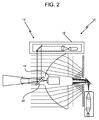
本発明の実施形態に関わる図1を参照すると、レーザスキャナ12の回転操作先端部(スキャナヘッド)10が図示されており、スキャナヘッド10は、スキャナヘッド10内に位置する光学素子(光学部品)内に直接一体化された、市販の比較的小さい、または、「小型」、「超小型」または「ピコ」プロジェクタ14を有する。プロジェクタ14は、周知のように、若干の処理能力を含んでもよい。プロジェクタ14は、コンピュータまたはレーザスキャナ12の処理装置と接続、または、通信してもよく、当該コンピュータまたは処理装置は、スキャナ12と一体化する(例えば、スキャナヘッド10内に位置する)か、または、スキャナ12と離れていても(例えば、ラップトップコンピュータ)よい。スキャナヘッド10は、一般的に、レーザスキャナの使用中、地面または他の表面に配置される(図示しない)支持三脚に取り付けられる。図2を参照してより詳細に説明すると、プロジェクタ14は、スキャナヘッド10内の光学部品を介して、一般的に、ヘッド10の水平軸の周りを360度、比較的高速に回転する回転走査ミラー16上に、様々な画像、データまたは他の情報を送信し、ミラー16は、(図示しない)表面に向けて画像、データまたは他の情報を表示のために投影する。スキャナヘッド10自体は、ヘッド10の垂直軸の周りを360度、比較的より低速で回転してもよい。
Referring to FIG. 1 relating to an embodiment of the present invention, a rotational operation tip (scanner head) 10 of a
本発明の様々な実施形態は、レーザスキャナ、レーザ追跡装置、白色光スキャナまたは類似の種類の技術的装置または機器を含むが、それらに限定されない、3次元測定装置または計測に一般的に用いられる機器に、このような比較的小さな画像またはデータプロジェクタを一体化または付加する形態を含む。本発明の実施形態において、プロジェクタは、レーザスキャナ12またはレーザ追跡装置内に一体化されてもよく、投影された画像、データまたは他の情報は、測定機器12自身からのデータまたは情報、測定機器12によって以前に取得されたデータまたは情報、または、他のソースからのデータまたは情報を用いて制御される。以下に詳細に説明するように、投影された画像またはデータにより、測定セッション中に有用な様々な種類の情報が視覚化されるか、または、投影された画像またはデータは、機器12によって以前に取得されたデータの視覚化を支援することができる。投影された視覚情報は、例えば、書かれた命令、ハイライトされた測定ポイント、データを取得する箇所が示された領域やデータの品質に関するリアルタイムのフィードバックなど、操作者にガイダンスを提供するような種類の情報でもよい。操作者に提供されるこの視覚情報は、例えば、視覚的な合図、文字列の形式または情報の他の視覚形式でもよい。
Various embodiments of the present invention are commonly used for three-dimensional measurement devices or measurements, including but not limited to laser scanners, laser tracking devices, white light scanners or similar types of technical devices or equipment. The device includes a form in which such a relatively small image or data projector is integrated or added. In an embodiment of the present invention, the projector may be integrated into the
さらに、プロジェクタは、上述した、例えば、微小電気機械システム(MEMS)技術、液晶ディスプレイ(LED)または反射型液晶素子(LCOS)技術に基づいた、小型、超小型またはピコプロジェクタなどのプロジェクタの種類のうち1つではなく、1つ以上の市販の検流計またはポリゴンスキャナを含んでもよい。例えば、一般的に、2つの検流計または2つのポリゴンスキャナを関連するミラーとともに用いて、所望の画像、データまたは情報を、所望のパターンで、2次元で対象面に投影する。レーザスキャナ12の場合、検流計ミラーは、対象に向かって反射する回転ミラー上に画像または他の情報を投影する。レーザスキャナ12のメインミラーの回転、及び、画像または他の投影された情報を作成するレーザスキャナ12の検流計ミラーの回転は、同期している。このため、レーザスキャナは、レーザ光が示すものに対して画像が生成されるのと同じように画像を形成する。レーザ追跡装置の場合(以降詳細に検討する)、検流計ミラーは、対象上に直接、画像または他の情報を投影する。追跡装置に配置されたプロジェクタによって投影されたパターンの大きさを、追跡装置のヘッドを比較的広域を対象にするように動かすと同時に、プロジェクタからのパターンを動的に変更することによって、拡大して、空間の比較的広い領域に所望の画像を生成してもよい。このように、レーザ追跡装置のヘッドは、検流計ミラーのような役割を果たす。使用の際、検流計またはポリゴンスキャナは、ピコプロジェクタからの光と比較して、画像またはデータ投影のため、比較的、より強力で、明るく、より効率的なレーザビームを供給することができる。
In addition, projectors are of the type of projectors described above, such as small, ultra-compact, or pico projectors based on, for example, microelectromechanical system (MEMS) technology, liquid crystal display (LED) or reflective liquid crystal device (LCOS) technology. One or more commercially available galvanometers or polygon scanners may be included instead of one. For example, typically two galvanometers or two polygon scanners are used with associated mirrors to project a desired image, data or information in a desired pattern in two dimensions onto a target surface. In the case of the
多くの場合、2次元パターンが投影される物体の表面上で、投影された画像をできる限り鮮明にするために焦点調節機構を設けることが有利である。焦点調節機構は、一般的に、1つ以上のレンズを動かす機械的アクチュエータを備える。 In many cases, it is advantageous to provide a focusing mechanism on the surface of the object on which the two-dimensional pattern is projected in order to make the projected image as sharp as possible. The focus adjustment mechanism typically comprises a mechanical actuator that moves one or more lenses.
MEMS、LCD、LCOS及び他の種類のピコプロジェクタは、今日、一般的に、カラー投影パターンを供給する。色は、物体についての情報を提供するのに有利に用いられるだろう。 MEMS, LCD, LCOS and other types of pico projectors today typically provide color projection patterns. Color may be advantageously used to provide information about the object.
レーザスキャナ及びレーザ追跡装置は、多くの場合、手動で照準を定める必要なく、または、装置12のセンサモジュールを動かす必要なく、スキャナまたは追跡機器または装置12が、自動的に広い領域またはオブジェクトの走査、または、装置12の可動範囲内での移動可能対象(例えば、再帰反射器)の追跡を行うことができるように、モータ及び/またはジンバルに搭載された光学部品、センサ、ミラー及び/またはレーザ源を採用する。
Laser scanners and laser tracking devices often do not require the aiming manually or move the sensor module of the
図2を参照すると、レーザスキャナ10のある実施形態において、レーザ光源18から放出されたレーザ光は、ミラー20を用いて導かれる。ミラー20の反射面が、レーザ光源18のある波長の光を反射し、他の波長の光を通すように被膜する技術(例えば、「2色性」被膜)が知られている。このような実施形態により、レーザ18から放出されたレーザビームを回転走査ミラー16(図1)に反射する角度付きミラーの後ろに、小型プロジェクタ14を搭載することができる。図2に示す実施形態において、レーザビームを向けるのに用いられるモータ、符号器及び駆動回路は、同時に、走査ミラー16(図1)を介してプロジェクタ14のビームも導く。
Referring to FIG. 2, in one embodiment of the
このように、ある実施形態において、レーザスキャナ12に関連付けられたコンピュータまたは処理装置は、いくつかの数学的な計算を行ってプロジェクタ14からの画像またはデータを、回転走査ミラー16上に正確に位置づける必要があるだろう。これらの計算は、当業者には、明らかである。すなわち、投影された画像またはデータは、画像またはデータが歪んだり、汚れないようにミラー16の回転を考慮して補償される。例えば、プロジェクタ14によってミラー16上に投影された画像は、動的に偏光されて投影面(例えば、壁)上に静止した画像を提供する。ミラー16を回転させる理由の1つには、一般的に、レーザの安全性の理由がある。別の実施形態では、計測の理由から、レーザビームを回転走査ミラー16に提供するレーザを止め、ミラー16を静止位置に保持し、その後、プロジェクタ14が、画像またはデータを含む比較的弱い光をミラー16に供給してもよい。これらの実施形態において、静止中のミラー16を数学的に修正する必要は、一般的にない。修正する必要がある場合、ミラー16の反射面に投影された画像の大きさは、スキャナから投影面までの距離に応じて調整される。この調整は、例えば、プロジェクタが発散パターンの光を放出する場合、及び、投影面上の画像が固定サイズを有することを目的としている場合、行われる。この場合、スキャナの距離測定機能により、プロジェクタ14が投影された画像の大きさを正確に調整するのに必要な情報が提供される。
Thus, in certain embodiments, a computer or processing device associated with
プロジェクタ14から対象面上に投影された画像、データまたは他の情報は、画像、データまたは他の情報が、回転走査ミラー16の特定の角度と一致して機械的または電気的に閃光されるように制御されたタイミングを有してもよい。また、計測の理由からスキャナ12によって用いられたレーザビームは、プロジェクタ14から供給された画像、データまたは他の情報に対して、互いに排他的に(例えば、多重化されて)供給されてもよい。すなわち、レーザビームと、投影された光パターンまたはデータとは、必要な条件ではないため、同時に「ある」(すなわち、投影される)必要はない。または、レーザビームと、投影された光パターンとは、同時に投影されてもよい。一般的に、本発明の実施形態に関わる、レーザスキャナ12の投影モードは、スキャナ12の走査モードに関係または依存しない。
The image, data or other information projected from the
図3を参照すると、本発明の別の実施形態において、プロジェクタ14は、図1及び図2の実施形態のようにレーザスキャナ12の測定光学部品と一列に設置される代わりに、例えば、レーザスキャナヘッド10の最上部の多軸電動ジンバル22に取り付けられる。これにより、投影システム14を、図1及び図2に示す完全に一体化した実施形態に対応しない既存のレーザスキャナ機器12に付加することができる。図3の実施形態は、ある状況において、実装がより簡単で、安価である。このような実施形態において、プロジェクタ14が設置されたジンバル22は、3次元測定装置12の光学部品と同期して駆動され、照準が定められるので、プロジェクタの画像は、確実に、レーザスキャナ12が測定を行う対象領域と同じ領域に向けられる。この特徴は、プロジェクタ12をガイダンスまたはデータ提示に用いる場合、利点を有する。または、独立して設けられたプロジェクタ14に対して、主装置の光学部品と異なる領域に画像を投影するように命令してもよい。
Referring to FIG. 3, in another embodiment of the present invention, the
3次元レーザスキャナ12やレーザ追跡装置などの3次元計測装置の、測定する物体、部分または構造に対する位置及び方向は、既知の技術を用いて参照点または部分または物体特徴を特定することによって構築されてもよい。一旦、座標系が構築されると、3次元計測装置(例えば、レーザスキャナ)12及びプロジェクタ14は、同期され、装置12の一部として装置12に接続された外部コンピュータ、または、装置の位置を処理し、装置の光学部品の方向を制御することができる装置12の一部として搭載されたコンピュータによって、比較的高い精度で制御される。これにより、投影された画像を、投影する表面に一致するように加工、拡大縮小及び制御することができ、プロジェクタ14の方向が変更すると画像を更新して、常に同期し、環境に固定させることができる。
The position and orientation of a three-dimensional measuring device, such as the three-
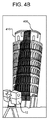
本発明の実施形態に関わるレーザスキャナ12などのコンピュータに制御された3次元測定装置と一体化されるか、または、搭載されたプロジェクタ14の様々な実施または利用は、測定する部分の表面上への、例えば、視覚的な合図、文字列または他の形式でのデータ、文字列、命令、画像またはガイダンスの投影を含むが、これらに限定されない。また、部分またはパラメータの変更の視覚化のため、以前に走査/測定されたデータまたは設計意図を示すCADデータの投影されたオーバーレイの提供も含む。3次元走査データでは、この提供は、(1)事故の以前と以後または修理の以前と以後の車体の比較、(2)計画された機器の取り付けの実際に完成した取り付けとのCAD設計の比較、(3)部品、機器設定、組立ライン、壁または建物への提案された変更の視覚化、(4)検査の方法としての図面と比較した部品設計の視覚化、(5)可視表面上に、設計図または工事中に撮られた走査図のCADデータを投影することによる、壁、天井または床の裏側のスタッド、パイプ、電気配線及び管工事などの隠れた特徴(図5)の視覚化、(6)3次元CAT走査、3次元X線または他の3次元診断データの画像を身体に投影して、人間または動物の身体の皮膚の下にある要素を可視化することによる、外科手術の一環としての、臓器、腫瘍、血管、骨または他の身体的特徴の位置の特定の視覚的補助の提供、(7)犯罪現場の前後の視覚化、(8)等高線の部分への投影による、例えば、やすりかけ、研磨またはラップ仕上げ、または、例えば、一液形エポキシ充填剤での充填による除去すべき部分の領域の指示、(9)従属部品が、例えば、ボルト、ねじ、または、接着剤により物体に取り付けられるべき領域を示すマークの投影、(10)部品の整列を補助するための線、曲線、マークまたは基準特徴の投影、及び、(11)例えば、図4に示すような、摩耗、沈下、腐敗、風化または一般的な経時的劣化の影響を受ける、考古学的な遺跡、歴史的建物、橋、線路、道路及び他の設備の(連続的な走査による)経時的な劣化または移動の視覚化、さらには、船、航空機、宇宙船(例えば、スペースシャトルのタイル)のような大型輸送手段の摩耗及び損傷の検査及び視覚化を含む。具体的には、図4Aの1つの図400及び図4の右側の傾いている図400は、図4A及び図4Bにおいて右側に傾いたピサの斜塔を示し、(図4Bに点線で示す)塔の直立した垂直な画像410は、本発明の様々な実施形態に関わるプロジェクタ14を有するレーザスキャナ12によって図4Bの傾いた塔の図400の上に(部分的に)投影されている。これにより、ピサの斜塔の経時的な右側への移動または「傾き」量を示している。通常、塔の直立した垂直な画像410の左側の(点線)部分は、傾いた塔に投影されたり、他の面に投影されたりしないため、見ることはないことに留意されたい。すなわち、この塔の直立した垂直な画像410の左側の(点線)部分は、自由空間に投影される。その代わり、通常、塔400に投影された直立した垂直な画像410の右側の影付き部分または塗りつぶされた部分のみが見える。図4Bでは、例示のため、塔の直立した垂直な画像410の全体を示している。
Various implementations or uses of a
制御された投影画像の有用性をさらに拡大するため、多数のプロジェクタ14をレーザスキャナ12などの単一の装置に組込んでもよい。これにより、画像対象の範囲を、レーザスキャナ自身によって遮られる比較的小さな領域(例えば、スキャナヘッド10が三脚に取り付けられる位置)を除く可能性はあるが、究極的には走査装置の周囲360度まで増加できる可能性がある。
本発明の他の実施形態において、同期された画像は、レーザスキャナ12またはレーザ追跡装置と独立して、例えば、ジンバル式のコンピュータで制御される取り付け具の上、または、測定されてレーザスキャナ12または追跡装置に知られている固定位置に搭載された多数のプロジェクタ14によって生成されてもよい。これらの実施形態において、各プロジェクタ14は、レーザスキャナ12または追跡装置、または、レーザスキャナ12または追跡装置に取り付けられたコンピュータによって制御され、領域の座標系を構築するのに用いられてもよい。これらの実施形態により、投影された画像は、比較的広い対象範囲を同時に提供するとともに、さもなければ、レーザスキャナ12自身を含む機器または特徴によって遮られてしまう領域の画像投影を支援する。このプロジェクタ14のアレイによって投影された画像は、その後、中央コンピュータまたはレーザスキャナ12または他の計測装置によって管理及び制御され、投影された画像またはデータまたは他の情報の、拡大縮小、大きさの調整、及び、環境の物体への適切な位置合わせが行われる。例えば、プロジェクタ14は、画像、データ、または、レーザスキャナ12が現在指示している方向及び/または方位に関する他の情報を投影する。例として、人または他の物体の動きは、レーザスキャナ12によって追跡され、その後、画像またはデータが、プロジェクタ14を有するレーザスキャナ12によって、人または物体の位置及び/または方向に応じて投影されてもよい。
In other embodiments of the present invention, the synchronized image is independent of the
本発明の実施形態は、投影された画像が、投影される表面に位置を合わせられるように、環境の一部または環境に基本座標系を構築することができる、あらゆるコンピュータ制御照準システムに適用される。本発明の他の実施形態は、エンターテインメントの目的に利用されてもよく、例えば、部屋の周囲の壁への映画の投影を含む。例えば、移動する物体(例えば、人)が、静止環境内で追跡される場合、環境内の投影された画像は、例えば、人の動き、動作または頭の方向に応じて自動的に調整されてもよい。これは、ゲーム機用のゲームやバーチャルリアリティ技術に関わる。しかし、3次元空間の復元は、2次元のゲーム技術とは異なる。例として、システムは、レーザスキャナまたは追跡装置に建物の周囲を歩く人を検出及び追跡させて、その間ずっと、人が見る壁に情報を投影してもよい。プロジェクタは、空間の360度を網羅することはできないが、人が見ている場所に選択的に投影することで、3次元空間に亘って投影されている感覚を与えることができる。 Embodiments of the invention apply to any computer controlled aiming system that can build a basic coordinate system in a part of the environment or in the environment so that the projected image can be aligned with the projected surface. The Other embodiments of the invention may be used for entertainment purposes, including, for example, projection of a movie onto a wall around the room. For example, if a moving object (eg, a person) is tracked in a static environment, the projected image in the environment is automatically adjusted depending on, for example, the person's movement, movement or head direction Also good. This relates to games for game machines and virtual reality technology. However, the restoration of the three-dimensional space is different from the two-dimensional game technology. As an example, the system may cause a laser scanner or tracking device to detect and track a person walking around a building and project information onto the wall that the person sees throughout. Although the projector cannot cover 360 degrees of space, it can give a sense of being projected over a three-dimensional space by selectively projecting to a place where a person is looking.
図5を参照すると、プロジェクタ14が、壁26などの表面に「隠れた特徴」24を投影する本発明の実施形態に関わる、プロジェクタ14を有するレーザスキャナ12が図示される。隠れた特徴は、例えば、壁26、天井、床または他の可視表面の裏側にあるスタッド、パイプ、電気配線及び管工事などの物体を含む。作業者は、壁表面26の裏側に何が厳密に位置するか、及び/または、壁表面26の裏側のこれら物の正確な位置が分からない。作業者に壁表面26の裏側にある物の画像及びそれらの物の正確な位置を提供することは有益だろう。一般的に、隠れた特徴についてのこの情報は、例えば、CAD設計データとして利用可能である。
Referring to FIG. 5, a
本発明の実施形態に関わる、隠れた特徴の投影は、例えば、まず、様々な建築段階(例えば、骨組み、配線、配管、HVACなど)の間、家などの建物をレーザスキャナ12を用いて走査して、建物の様々な構造の詳細のスキャン点群データを取得することにより、行われてもよい。走査のある段階が終了して画像及びデータを収集した後、プロジェクタ14を有するレーザスキャナ12を用いて、走査工程で取得された様々な「現実の」画像及び/またはデータを、壁、天井、床などに投影してもよい。または、建物の様々な表面にCAD設計の「未来の」データを表面に投影してもよい。投影される画像及び/またはデータが現実の画像及び/またはデータであっても、あるいは、未来の画像及び/またはデータであっても、これらの表面への隠れた特徴の投影は、人が、例えば、壁の裏側のスタッドの正確な位置に穴を開けるなどの作業を実行するのを助けるだろう。本発明のこれらの実施形態により、プロジェクタ14を有するレーザスキャナ12のユーザは、これらの物体また特徴の正確な位置を特定することができるので、他の物体へ損害を与えることがなく、これらの隠れた物体または特徴の位置を特定しようとするのに時間を無駄にすることがない。
Hidden feature projections according to embodiments of the present invention, for example, first scan a building, such as a house, using a
図5に示す実施形態と同じように、隠れた特徴は、皮膚によって覆われた人体内の特徴を含んでもよい。例えば、プロジェクタ14は、患者の皮膚にデータを投影して、医師または外科医が、アクセス及び/または外科手術を施す人体の内部器官の位置を正確に特定するのを助けてもよい。手術室で、例えば、医師は、プロジェクタ14を有するレーザスキャナ12を用いて、切開を行ったり、腫瘍を見つけるために正確な位置を判定し、この位置を3次元コンピュータ断層撮影(CAT)データと相互に関連付けてもよい。この場合、プロジェクタ14は、画像を患者に投影し、マーカまたはCAT走査画像の実際の複製を提供して外科医をガイドしてもよい。手動で走査されるロボットによって遠隔で行われる手術において、上述した方法と同じようにこの投影システム14を用いてもよい。
Similar to the embodiment shown in FIG. 5, the hidden features may include features within the human body that are covered by the skin. For example, the
隠れた要素を表示する以外に、例えば、建設地域や工学装置において、プロジェクタは、取り付け後にどのように見えるか、領域を表示してもよい。例えば、図5において、壁表面26が配置された前であって、パイプや他の建築要素が壁表面26の後ろに設置される前に、スキャナは、領域の所望の外見を表示することによって建築業者にガイダンスを提供することができる。 In addition to displaying hidden elements, for example, in construction areas and engineering equipment, the projector may display an area of what it will look like after installation. For example, in FIG. 5, before the wall surface 26 is placed and before the pipes or other building elements are installed behind the wall surface 26, the scanner displays the desired appearance of the area. Guidance can be provided to contractors.
図6から図11を参照すると、本発明の別の態様に関わる、一体化または搭載されたプロジェクタを有するレーザ追跡装置30の実施形態が図示される。図6において、レーザ追跡装置30は、方位ベース36に搭載され、方位軸38の周囲を回転する天頂キャリッジ34を備えるジンバル式ビーム操作機構32を備える。ペイロード40は、天頂キャリッジ34に搭載され、天頂軸42の周囲を回転する。天頂機械的回転軸42及び方位機械的回転軸38は、追跡装置30の内部で、一般的に、距離測定値の起源であるジンバル点44で、直交して交差する。レーザビーム46は、実質的にジンバル点44を通過し、天頂軸42に対して直交して向けられる。すなわち、レーザビーム46は、天頂軸42に垂直な平面にある。レーザビーム46は、ペイロード40を天頂軸42及び方位軸38の周囲を回転させる、追跡装置30内に配置された(図示しない)モータによって所望の方向に向けられる。追跡装置30の内部に配置された、(図示しない)天頂及び方位角符号器は、天頂機械的回転軸42及び方位機械的回転軸38に取り付けられ、比較的高い精度で回転角を示す。レーザビーム46は、球状に搭載された再帰反射器(SMR)などの外部再帰反射器48へ進む。ジンバル点44と再帰反射器48との半径方向距離及び天頂及び方位軸42及び38の回転角を測定することによって、再帰反射器48の位置が追跡装置30の球状座標系内で求められる。
With reference to FIGS. 6-11, an embodiment of a
レーザビーム46は、1つ以上のレーザ波長を有してもよい。明快及び簡潔にするために、以下の記載において、図6に示す種類の操作機構を前提とするが、他の種類の操作機構も可能である。例えば、方位及び天頂角38及び42の周囲を回転するミラーにレーザビームを反射させてもよい。このようなミラーに使用例は、Lau等による特許文献5に開示されている。本明細書に記載される技術は、利用する操作機構の種類に関係なく適用可能である。
The
レーザ追跡装置30において、1つ以上のカメラ50及び光源52がペイロード40上に配置される。光源52は、1つ以上の再帰反射器の対象48を照射する。光源52は、電気的に駆動されてパルス光を繰り返し放出する。各カメラ50は、感光性アレイ及び感光性アレイの前に配置されたレンズを備える。感光性アレイは、CMOSまたはCCDアレイでよい。レンズは、例えば、30または40度の比較的広い視野を有してもよい。レンズの目的は、レンズの視野内の物体の感光性アレイ上に画像を形成することである。各光源52は、光源52からの光が各再帰反射器の対象48に反射してカメラ50に向かうように、カメラ50の近くに配置される。このように、再帰反射器の画像は、その画像の発光点が背景物体よりも明るく、パルス状であるので、感光性アレイ上の背景から容易に区別される。実施形態において、2つのカメラ50及び2つの光源52が、レーザビーム46の進路に対して対称的に配置される。このように2つのカメラ50を用いることによって、三角測量の原理を用いて、カメラ50の視野内のあらゆるSMR48の3次元座標を求めることができる。さらに、SMR48が2点間を移動する間、SMR48の3次元座標を監視することができる。この目的のための2つのカメラの利用は、Bridgesによる特許文献12に記載されている。
In the
1つ以上のカメラ50及び光源52の他の配置も可能である。例えば、光源52及びカメラ50は、追跡装置30によって放出されたレーザビーム46と同軸または略同軸であってもよい。この場合、光学フィルタリングまたは同様の方法を用いて、カメラ50の感光性アレイが追跡装置30からのレーザビーム46で飽和することを避ける必要があるだろう。
Other arrangements of one or
別の考えられる配置としては、追跡装置30のペイロードまたはベース上に配置された1つのカメラ50の利用がある。1つのカメラ50は、レーザ追跡装置30の光学軸から外れて配置されると、再帰反射器48への方向を定義する2つの角度についての情報は提供するが、再帰反射器48までの距離は提供しない。多くの場合、この情報は十分だろう。1つのカメラ50を用いる際、再帰反射器48の3次元座標が必要な場合、一策として、方位角方向に追跡装置30を180度回転させ、その後、再帰反射器48に向くように天頂軸42を反転させる方法がある。これにより、対象48を2つの異なる方向から見ることができ、三角測量を用いて再帰反射器48の3次元位置を求めることができる。
Another possible arrangement is the use of a
別の策として、対象48の測定と撮像とを切り替える方法がある。このような方法の例は、Bridges等による特許文献13に記載されている。他のカメラの配置も可能であり、本願に記載されている方法とともに用いることができる。
As another measure, there is a method of switching between measurement and imaging of the
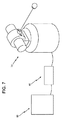
図7に示すように、補助装置60は、通常、レーザ追跡装置30の一部である。補助装置60の目的は、レーザ追跡装置に電力を供給すること、及び、場合によっては、システムにコンピュータ機能及びクロック機能を提供することである。補助装置60の機能を追跡装置本体に移すことによって、補助装置60を完全になくすことができる。ほとんどの場合、補助装置60は、汎用コンピュータ62に取り付けられる。汎用コンピュータ62に搭載されたアプリケーションソフトウェアは、リバースエンジニアリングなどのアプリケーション機能を提供してもよい。コンピュータ機能を直接レーザ追跡装置30に構築することによって汎用コンピュータ62をなくすこともできる。この場合、好ましくは、キーボード及びマウス機能を提供するユーザインターフェースが、レーザ追跡装置30に内蔵される。補助装置60とコンピュータ62との接続は、無線でも電線のケーブルを介してもよい。コンピュータ62は、ネットワークに接続されてもよく、補助装置60も、ネットワークに接続されてもよい。複数の機器、例えば、多数の測定機器またはアクチュエータが、コンピュータ62または補助装置60を介して、互いに接続されてもよい。
As shown in FIG. 7, the
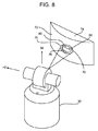
図8を参照すると、追跡装置30(図9から10)内に一体化され、パターン70を被加工物などの物体74の表面72上に投影する(図示しない)内部プロジェクタ94を有するレーザ追跡装置30が図示される。このようなパターン70は、例えば、特徴76をハイライトして、追跡装置30による測定結果を円78により取得するのに用いてもよいし、計器80を覆い、測定装置30が測定点を取得するのに用いてもよい。
Referring to FIG. 8, a laser tracking device having an internal projector 94 (not shown) that is integrated into the tracking device 30 (FIGS. 9-10) and projects a
図9を参照すると、図6のレーザ追跡装置30の様々な内部構成要素が図示される。構成要素は、干渉計(IFM)、絶対距離計(ADM)またはその両方を含む、1つ以上の距離計器80を含む。距離計80からは、可視光または赤外線、または、その両方である、1つ以上のレーザビーム82が放出される。出射レーザビーム82は、第1ビームスプリッタ84を通過する。出射レーザビーム82が再帰反射器48(図6)に向けられる場合、戻り経路上で、この再帰反射されたレーザビーム82は、第1ビームスプリッタ84に反射し、位置検出器88へ進む。レーザ追跡装置30の制御システムは、位置検出器88上の光の位置を用いて、出射レーザビーム82を再帰反射器48の中心に保ち、それにより、追跡機能を有効にする。出射レーザビーム82が、再帰反射器84ではなく、被加工物74(図8)に向けられる場合、戻ってくるレーザビーム86の位置検出器88上の位置は、重要ではない。第1ビームスプリッタ84を通過した後、出射レーザビーム82は、ビーム拡大器90を通過し、ビーム拡大器90は、ビームが(再帰反射器48に向けて)順方向に進んでいる場合、出射レーザビーム82の直径を大きくする。その後、出射レーザビーム82は、第2ビームスプリッタ92を通過する。プロジェクタ94(図1から図5の実施形態のプロジェクタ14と類似する)からの光は、第2ビームスプリッタ92上にレーザ光96のパターンを送る。第2ビームスプリッタ92の反射光96は、距離計80からの出射レーザビーム82と合成され、合成された光98は、再帰反射器48または被加工物74へ進む。レーザビーム98が被加工物74に向けられる場合、ビーム82に含まれる可視光を止めてもよい。これにより、投影されたビーム98が、よりはっきりと見えるようになるだろう。
Referring to FIG. 9, various internal components of the
図10を参照すると、第2ビームスプリッタ92及びプロジェクタ94が両方ともビーム拡大器90の前に配置されている以外は図9のレーザ追跡装置と類似した、レーザ追跡装置30の様々な構成要素の実施形態が図示される。この方法の利点は、第2ビームスプリッタ92を、図9の実施形態に比べて小型にすることができることである。欠点は、プロジェクタ94の適切な配置がより難しくなることである。
Referring to FIG. 10, various components of the
図6から図10に図示され、本明細書に記載される実施形態において、レーザ追跡装置30は、レーザ追跡装置30の内部構成要素に一体化されたプロジェクタ94を有する。しかし、他の実施形態では、プロジェクタ94をレーザ追跡装置30に搭載するか、または、取り付けてもよい。例えば、図11は、レーザ追跡装置30が追跡装置本体の最上部に搭載されたプロジェクタ14を有する実施形態を示す。プロジェクタ14は、追跡装置本体に堅固に搭載されてもよいし、または、図3に示すレーザスキャナ12の実施形態のプロジェクタと同様に、ジンバル機構22を用いて搭載されてもよい。
In the embodiment illustrated in FIGS. 6-10 and described herein, the
別の実施形態において、プロジェクタは、レーザビーム82及び86を伝送する光軸からオフセットされる。プロジェクタを光軸から移動させることで、光ビーム82を伝送する光学系をより小型にでき、プロジェクタから追跡装置の外部の領域までの距離を小さくできるので、より大きな発散角を有する2次元パターンを作成することができる。この実施形態において、天頂(水平軸)回転のための独立軸は必要ない。
In another embodiment, the projector is offset from the optical axis transmitting
図6から図11のレーザ追跡装置30を参照して説明した本発明の様々な実施形態において、図1から図5を参照して説明した本発明のレーザスキャナの実施形態のプロジェクタ14と同様に、プロジェクタ94は、画像、データまたは他の情報を投影することができる。このような投影された情報は、レーザ追跡装置30を用いた測定セッションの間、有用な様々な種類の情報の視覚化を操作者に提供するか、または、投影された画像またはデータは、機器12によって事前に取得されたデータの視覚化を助けることができる。投影された視覚情報は、例えば、書かれた命令、ハイライトされた測定ポイント、データを取得する箇所が示された領域やデータの品質に関するリアルタイムのフィードバックなど、操作者にガイダンスを提供するような種類の情報でもよい。操作者へ提供されるこの視覚情報は、例えば、視覚的な合図、文字列の形式または情報の他の視覚形式でもよい。投影された画像の利用は、一般的に、レーザスキャナと同じである。レーザ追跡装置で特に重要なことは、(1)構造から材料を取り除くか、または、構造に材料を付加する場所をマークが示す投影、及び、(2)構造に構成要素を付加する場所をマークが示す投影である。
In the various embodiments of the invention described with reference to the
好適な実施形態を示し、説明してきたが、本発明の精神及び範囲を逸脱せずに、様々な修正及び置換を行ってもよい。従って、本発明は、限定ではなく例示の目的で記載されたものであると理解されたい。 While the preferred embodiment has been shown and described, various modifications and substitutions may be made without departing from the spirit and scope of the invention. Accordingly, it is to be understood that the present invention has been described by way of illustration and not limitation.
従って、本明細書に記載した実施形態は、全ての点において、限定ではなく例示として考えられるべきであり、発明の範囲は、前述の記載ではなく、添付の請求の範囲に示されるため、請求の範囲と同等の意味及び範囲内の変更は、全て本明細書に包含されるものである。 Accordingly, the embodiments described herein are to be considered in all respects as illustrative and not restrictive, and the scope of the invention is indicated by the appended claims rather than by the foregoing description. All meanings within the scope and changes within the scope are intended to be embraced herein.
Claims (20)
第1ポイントに光ビーム(46)を送るように構成された光源(18)と、
前記第1ポイントから反射して戻ってきた前記光ビーム(46)の一部を第1電気信号に変換するように構成された光学検出器と、
前記座標測定装置(12、30)から前記第1ポイントまでの第1距離を算出するように構成された第1処理装置であって、前記算出は、前記第1電気信号及び空気中の光の速度に少なくとも一部基づいて行われる、第1処理装置と、
前記座標測定装置(12、30)の本体内に一体化されるか、または、前記座標測定装置(12、30)の本体の所定の場所に搭載されたプロジェクタであって、当該プロジェクタ(14、94)は、物体(74)に可視光の2次元パターン(70)を投影するように構成され、投影された可視光は、画像(410)、データまたは情報を示し、第2処理装置から受信した命令に応答して前記2次元パターン(70)を生成するように構成されたプログラム可能な画素のアレイを含む、プロジェクタ(14、94)と、
前記光ビーム(46)及び光の2次元パターン(70)を第1軸(38)の周りを第1角度だけ回転させるように構成されたビーム操作機構であって、前記光ビーム(46)を第2軸(42)の周りを第2角度だけ回転させるように構成されている、ビーム操作機構(32)と、
前記第1角度を測定するように構成された第1角度変換器と、
前記第2角度を測定するように構成された第2角度変換器と、を含む座標測定装置。 A coordinate measuring device (12, 30) having a three-dimensional coordinate system,
A light source (18) configured to send a light beam (46) to a first point;
An optical detector configured to convert a portion of the light beam (46) reflected back from the first point into a first electrical signal;
A first processing device configured to calculate a first distance from the coordinate measuring device (12, 30) to the first point, the calculation comprising the first electrical signal and light in the air. A first processing device based at least in part on the speed;
A projector that is integrated into the main body of the coordinate measuring device (12, 30) or is mounted at a predetermined location on the main body of the coordinate measuring device (12, 30), the projector (14, 94) is configured to project a two-dimensional pattern (70) of visible light onto the object (74), the projected visible light representing an image (410), data or information received from the second processing device A projector (14, 94) including an array of programmable pixels configured to generate the two-dimensional pattern (70) in response to a command received;
A beam manipulation mechanism configured to rotate the light beam (46) and a two-dimensional pattern (70) of light about a first axis (38) by a first angle, wherein the light beam (46) A beam manipulation mechanism (32) configured to rotate around the second axis (42) by a second angle;
A first angle transducer configured to measure the first angle;
And a second angle converter configured to measure the second angle.
前記光ビーム(46)を投影するように構成された第1光学系であって、第1光軸を有する第1光学系と、
前記光の二次元パターン(70)を投影するように構成された第2光学系であって、第2光軸を有する第2光学系と、を含む座標測定装置。 The coordinate measuring device (12, 30) according to claim 1, further comprising:
A first optical system configured to project the light beam (46), the first optical system having a first optical axis;
A coordinate measuring apparatus comprising: a second optical system configured to project the two-dimensional pattern (70) of light, the second optical system having a second optical axis.
Applications Claiming Priority (9)
| Application Number | Priority Date | Filing Date | Title |
|---|---|---|---|
| US38086910P | 2010-09-08 | 2010-09-08 | |
| US61/380,869 | 2010-09-08 | ||
| US13/006,524 | 2011-01-14 | ||
| US13/006,524 US20110178765A1 (en) | 2010-01-20 | 2011-01-14 | Multi-functional coordinate measurement machines |
| US13/006,468 US8683709B2 (en) | 2010-01-20 | 2011-01-14 | Portable articulated arm coordinate measuring machine with multi-bus arm technology |
| US13/006,468 | 2011-01-14 | ||
| US13/006,507 | 2011-01-14 | ||
| US13/006,507 US8533967B2 (en) | 2010-01-20 | 2011-01-14 | Coordinate measurement machines with removable accessories |
| PCT/US2011/050787 WO2012033892A1 (en) | 2010-09-08 | 2011-09-08 | A laser scanner or laser tracker having a projector |
Publications (2)
| Publication Number | Publication Date |
|---|---|
| JP2013539541A true JP2013539541A (en) | 2013-10-24 |
| JP2013539541A5 JP2013539541A5 (en) | 2014-04-03 |
Family
ID=44652026
Family Applications (1)
| Application Number | Title | Priority Date | Filing Date |
|---|---|---|---|
| JP2013528279A Pending JP2013539541A (en) | 2010-09-08 | 2011-09-08 | Laser scanner or laser tracking device having a projector |
Country Status (6)
| Country | Link |
|---|---|
| US (1) | US8638446B2 (en) |
| JP (1) | JP2013539541A (en) |
| CN (1) | CN103003713B (en) |
| DE (1) | DE112011102995B4 (en) |
| GB (1) | GB2501390B (en) |
| WO (1) | WO2012033892A1 (en) |
Cited By (3)
| Publication number | Priority date | Publication date | Assignee | Title |
|---|---|---|---|---|
| JP2014106167A (en) * | 2012-11-29 | 2014-06-09 | Hitachi Ltd | Laser projection method and laser projection device |
| JP2017218792A (en) * | 2016-06-07 | 2017-12-14 | 清水建設株式会社 | Construction management apparatus and construction management method |
| JP2020042667A (en) * | 2018-09-11 | 2020-03-19 | 株式会社インフォマティクス | Projection system, projection method, and program |
Families Citing this family (68)
| Publication number | Priority date | Publication date | Assignee | Title |
|---|---|---|---|---|
| US8897482B2 (en) * | 2008-02-29 | 2014-11-25 | Trimble Ab | Stereo photogrammetry from a single station using a surveying instrument with an eccentric camera |
| US9189858B2 (en) | 2008-02-29 | 2015-11-17 | Trimble Ab | Determining coordinates of a target in relation to a survey instrument having at least two cameras |
| US8900126B2 (en) * | 2011-03-23 | 2014-12-02 | United Sciences, Llc | Optical scanning device |
| WO2013093932A2 (en) * | 2011-09-29 | 2013-06-27 | Tata Consultancy Services Limited | Damage assessment of an object |
| CN103096141B (en) * | 2011-11-08 | 2019-06-11 | 华为技术有限公司 | A kind of method, apparatus and system obtaining visual angle |
| US8900125B2 (en) * | 2012-03-12 | 2014-12-02 | United Sciences, Llc | Otoscanning with 3D modeling |
| US9200899B2 (en) * | 2012-03-22 | 2015-12-01 | Virtek Vision International, Inc. | Laser projection system and method |
| US9245062B2 (en) * | 2012-03-22 | 2016-01-26 | Virtek Vision International Inc. | Laser projection system using variable part alignment |
| US8937657B2 (en) * | 2012-07-15 | 2015-01-20 | Erik Klass | Portable three-dimensional metrology with data displayed on the measured surface |
| US9057610B2 (en) * | 2012-11-03 | 2015-06-16 | Trimble A.B. | Robotic laser pointer apparatus and methods |
| US9644942B2 (en) | 2012-11-29 | 2017-05-09 | Mitsubishi Hitachi Power Systems, Ltd. | Method and apparatus for laser projection, and machining method |
| JP2014106837A (en) * | 2012-11-29 | 2014-06-09 | Sony Corp | Display control device, display control method, and recording medium |
| KR102048361B1 (en) * | 2013-02-28 | 2019-11-25 | 엘지전자 주식회사 | Distance detecting device and Image processing apparatus including the same |
| EP2787321B1 (en) | 2013-04-05 | 2015-09-16 | Leica Geosystems AG | Surface determination for objects using precise geodesic point determination and scanning |
| EP2787322B1 (en) | 2013-04-05 | 2017-10-04 | Leica Geosystems AG | Georeferencing of point clouds |
| EP2789972B1 (en) | 2013-04-12 | 2017-08-16 | Hexagon Technology Center GmbH | Measuring device with deformable optical element |
| US9234742B2 (en) | 2013-05-01 | 2016-01-12 | Faro Technologies, Inc. | Method and apparatus for using gestures to control a laser tracker |
| US9476695B2 (en) * | 2013-07-03 | 2016-10-25 | Faro Technologies, Inc. | Laser tracker that cooperates with a remote camera bar and coordinate measurement device |
| US9721304B1 (en) * | 2013-07-15 | 2017-08-01 | Liberty Mutual Insurance Company | Vehicle damage assessment using 3D scanning |
| US9964401B2 (en) | 2013-07-16 | 2018-05-08 | Polyrix Inc. | Inspection system for inspecting an object and inspection method for same |
| US20150042640A1 (en) * | 2013-08-07 | 2015-02-12 | Cherif Atia Algreatly | Floating 3d image in midair |
| CN103412391A (en) * | 2013-08-14 | 2013-11-27 | 中国科学院光电技术研究所 | Laser tracker based method for achieving optical system axis through and center alignment |
| EP2860492B1 (en) | 2013-10-09 | 2018-02-28 | Hexagon Technology Center GmbH | Measuring device for optically scanning an environment |
| DE102013017500B3 (en) | 2013-10-17 | 2015-04-02 | Faro Technologies, Inc. | Method and apparatus for optically scanning and measuring a scene |
| EP2881704B1 (en) * | 2013-12-04 | 2018-05-09 | Hexagon Technology Center GmbH | Systems and methods for automated measurement of an object and corresponding computer programme product |
| US9594250B2 (en) | 2013-12-18 | 2017-03-14 | Hexagon Metrology, Inc. | Ultra-portable coordinate measurement machine |
| JP6253973B2 (en) * | 2013-12-27 | 2017-12-27 | 株式会社トプコン | Surveying equipment |
| EP2916099B1 (en) | 2014-03-07 | 2020-09-30 | Hexagon Technology Center GmbH | Articulated arm coordinate measuring machine |
| WO2015191605A1 (en) * | 2014-06-09 | 2015-12-17 | The Johns Hopkins University | Virtual rigid body optical tracking system and method |
| WO2015197221A1 (en) * | 2014-06-25 | 2015-12-30 | Robert Bosch Gmbh | Locating system having a hand-held locating unit |
| EP2980526B1 (en) | 2014-07-30 | 2019-01-16 | Leica Geosystems AG | Coordinate measuring device and method |
| EP3201564B1 (en) * | 2014-09-30 | 2020-05-20 | Hexagon Metrology, Inc | System and method for measuring an object using x-ray projections. computer program product. |
| DE102014224851A1 (en) * | 2014-12-04 | 2016-06-09 | Siemens Aktiengesellschaft | Apparatus and method for displaying structural information about a technical object |
| CA2977945A1 (en) | 2015-03-03 | 2016-09-09 | Prenav Inc. | Scanning environments and tracking unmanned aerial vehicles |
| WO2016196292A1 (en) | 2015-05-29 | 2016-12-08 | Hexagon Metrology, Inc. | Coordinate measuring machine with object location logic |
| US10726534B1 (en) * | 2015-07-09 | 2020-07-28 | Lazer Layout, Llc | Layout projection |
| US10503265B2 (en) * | 2015-09-08 | 2019-12-10 | Microvision, Inc. | Mixed-mode depth detection |
| WO2017052521A1 (en) * | 2015-09-23 | 2017-03-30 | Hewlett-Packard Development Company, L.P. | Image projections |
| US10191479B2 (en) * | 2015-09-29 | 2019-01-29 | General Electric Company | Methods and systems for network-based detection of component wear |
| GB2544727A (en) * | 2015-11-16 | 2017-05-31 | Optonor As | Optical interferometry |
| WO2017127078A1 (en) * | 2016-01-21 | 2017-07-27 | Hewlett-Packard Development Company, L.P. | Area scanning and image projection |
| EP3203263B1 (en) | 2016-02-03 | 2018-04-18 | Sick Ag | Optoelectronic sensor and method for detecting objects |
| CN105716576B (en) * | 2016-03-29 | 2019-03-05 | 北京派特森科技股份有限公司 | A kind of long-range projection-type laser cross section instrument and its method |
| EP3226029A1 (en) * | 2016-03-30 | 2017-10-04 | Hexagon Technology Center GmbH | Laser scanner with referenced projector |
| CN105912029A (en) * | 2016-03-30 | 2016-08-31 | 上海卫星工程研究所 | Satellite scanning pendulum mirror control device for voice coil motor driving |
| CN105973211A (en) * | 2016-06-15 | 2016-09-28 | 常州华达科捷光电仪器有限公司 | Laser scanning lofting device |
| US10359507B2 (en) * | 2016-12-30 | 2019-07-23 | Panosense Inc. | Lidar sensor assembly calibration based on reference surface |
| EP3566178A4 (en) * | 2017-02-02 | 2020-08-26 | Prenav Inc. | Tracking image collection for digital capture of environments, and associated systems and methods |
| DE212018000168U1 (en) | 2017-03-02 | 2019-10-28 | Bem 15 Kft. | Optical device for dynamic reconstruction or simulation of competitive situations |
| US10642045B2 (en) | 2017-04-07 | 2020-05-05 | Microsoft Technology Licensing, Llc | Scanner-illuminated LCOS projector for head mounted display |
| US10508917B1 (en) * | 2017-04-20 | 2019-12-17 | The United States Of America As Represented By The Secretary Of The Navy | Spring-loaded target carrier for laser tracking |
| EP3450913B1 (en) * | 2017-08-30 | 2021-06-09 | Hexagon Technology Center GmbH | Surveying instrument for scanning an object and for projection of information |
| EP3460394B1 (en) * | 2017-09-26 | 2020-06-03 | Hexagon Technology Center GmbH | Surveying instrument, augmented reality (ar)-system and method for referencing an ar-device relative to a reference system |
| CN108387221A (en) * | 2018-01-17 | 2018-08-10 | 西安理工大学 | A kind of tunnel excavation speedy lofting device and setting out method |
| WO2020107123A1 (en) * | 2018-11-29 | 2020-06-04 | Ha Hieu Thuan Charles | Projection device for displaying construction plans |
| EP3671273B1 (en) * | 2018-12-18 | 2022-05-04 | Leica Geosystems AG | System for rough localization of moveable cooperative targets during laser tracker based industrial object measurement |
| CN110006339B (en) * | 2019-03-25 | 2021-08-10 | 北京卫星制造厂有限公司 | Antenna reflector composite material mold surface precision in-situ measurement method and system |
| CN110060771A (en) * | 2019-04-16 | 2019-07-26 | 江苏信美医学工程科技有限公司 | A kind of remote operation air navigation aid and device based on in-situ projection technology |
| EP3783305B1 (en) | 2019-08-21 | 2022-03-23 | Leica Geosystems AG | Drive system in a geodetic measurement instrument |
| EP3812701B1 (en) | 2019-10-23 | 2022-08-24 | Hexagon Technology Center GmbH | Online leveling calibration of a geodetic instrument |
| CN111452092B (en) * | 2020-03-31 | 2021-11-05 | 北京博清科技有限公司 | Adjusting method and system of laser tracking sensor, storage medium and welding equipment |
| CN111595255A (en) * | 2020-05-14 | 2020-08-28 | 南京航空航天大学 | Tunnel defect real-time prompting device and prompting method |
| JP2022015633A (en) * | 2020-07-09 | 2022-01-21 | 株式会社トプコン | Surveying device |
| CN112867136B (en) * | 2020-12-31 | 2022-11-15 | 思看科技(杭州)股份有限公司 | Three-dimensional scanning system and three-dimensional scanning method based on wireless peer-to-peer network |
| CN112747751A (en) * | 2021-01-05 | 2021-05-04 | 北京中科深智科技有限公司 | Indoor positioning method and positioning system |
| CN113325434A (en) * | 2021-04-16 | 2021-08-31 | 盎锐(上海)信息科技有限公司 | Explosion point display method and system for actual measurement actual quantity and laser radar |
| EP4354084A1 (en) | 2022-10-10 | 2024-04-17 | Hexagon Technology Center GmbH | In-the-field leveling calibration of a surveying instrument |
| CN116437016B (en) * | 2023-06-13 | 2023-10-10 | 武汉中观自动化科技有限公司 | Object scanning method, device, electronic equipment and storage medium |
Citations (9)
| Publication number | Priority date | Publication date | Assignee | Title |
|---|---|---|---|---|
| JPH10111130A (en) * | 1996-10-02 | 1998-04-28 | Sokkia Co Ltd | Target for center coordinate measurement |
| JP2001066158A (en) * | 1999-08-30 | 2001-03-16 | Wakayama Univ | Measurement result or analysis result projecting device and method |
| JP3274290B2 (en) * | 1994-09-19 | 2002-04-15 | 三菱電機株式会社 | Video display device and video display system |
| JP2004347585A (en) * | 2003-02-21 | 2004-12-09 | Fast:Kk | Inspection/analysis system for construction and civil engineering structure |
| JP2005293291A (en) * | 2004-03-31 | 2005-10-20 | Brother Ind Ltd | Image input/output device |
| JP2007101836A (en) * | 2005-10-04 | 2007-04-19 | Seiko Epson Corp | Projector |
| JP2008514967A (en) * | 2004-09-30 | 2008-05-08 | ファロ テクノロジーズ インコーポレーテッド | Absolute rangefinder to measure moving retroreflectors |
| JP2008224516A (en) * | 2007-03-14 | 2008-09-25 | Seiko Epson Corp | Construction support apparatus and construction support method |
| JP2010112875A (en) * | 2008-11-07 | 2010-05-20 | Sharp Corp | Projection device, projection device control method, and projection device control program |
Family Cites Families (382)
| Publication number | Priority date | Publication date | Assignee | Title |
|---|---|---|---|---|
| US646811A (en) | 1899-07-17 | 1900-04-03 | John H Driller | Tack-puller. |
| US652411A (en) | 1900-03-06 | 1900-06-26 | Anthony W Thierkoff | Index for mechanical account apparatus. |
| US650711A (en) | 1900-03-20 | 1900-05-29 | Richard Eccles | Thill-coupling. |
| US1535312A (en) | 1923-09-15 | 1925-04-28 | Hosking Richard Thomas | Waterproof covering for cameras |
| US1918813A (en) | 1932-02-02 | 1933-07-18 | Kinzy Jacob | Camera case |
| US2316573A (en) | 1940-04-01 | 1943-04-13 | W & L E Gurley | Instrument case |
| US2333243A (en) | 1942-12-07 | 1943-11-02 | Morrison Brothers Company | Detachable coupling |
| US2702683A (en) | 1951-08-17 | 1955-02-22 | Harold L Green | Magnetic holder for gasoline filling spout caps |
| US2748926A (en) | 1952-03-17 | 1956-06-05 | Matthew T Leahy | Micrometer support |
| US2983367A (en) | 1958-06-25 | 1961-05-09 | Lee W Parmater | Plural instrument carrying case |
| US2924495A (en) | 1958-09-15 | 1960-02-09 | Merz Engineering Inc | Instrument case |
| GB894320A (en) | 1959-03-13 | 1962-04-18 | Famatex G M B H Fabrik Fur Tex | Tentering device |
| US2966257A (en) | 1959-11-03 | 1960-12-27 | Gen Radio Co | Instrument carrying case |
| US3066790A (en) | 1961-11-13 | 1962-12-04 | American Optical Corp | Instrument carrying case |
| US3458167A (en) | 1966-12-28 | 1969-07-29 | Fmc Corp | Balancing mechanism |
| US4138045A (en) | 1977-06-15 | 1979-02-06 | Engineered Products, Inc. | Camera case |
| SE425331B (en) | 1979-01-17 | 1982-09-20 | Erling Nilsson | DEVICE FOR DETECTING CIRCULAR RUBBING IN A PATIENT'S EXTREMITER BASED ON THE SKIN TEMPERATURE OF THE EXTREMITES |
| US4667231A (en) | 1979-09-07 | 1987-05-19 | Diffracto Ltd. | Electro-optical part inspection in the presence of contamination and surface finish variation |
| US4340008A (en) | 1980-09-22 | 1982-07-20 | Mendelson Ralph R | Tilt indicator for shipping containers |
| JPS57132015A (en) | 1981-02-09 | 1982-08-16 | Kosaka Kenkyusho:Kk | Coordinate transformation device |
| US4457625A (en) | 1981-07-13 | 1984-07-03 | Itek Corporation | Self calibrating contour measuring system using fringe counting interferometers |
| US4506448A (en) | 1981-10-27 | 1985-03-26 | British Aerospace Public Limited Company | Teaching robots |
| US4424899A (en) | 1982-03-08 | 1984-01-10 | Western Electric Co., Inc. | Instrument carrying case |
| US4537233A (en) | 1983-06-21 | 1985-08-27 | Continental Emsco Company | Spring balance assembly |
| US4664588A (en) | 1984-03-09 | 1987-05-12 | Applied Robotics Inc. | Apparatus and method for connecting and exchanging remote manipulable elements to a central control source |
| US4606696A (en) | 1984-06-25 | 1986-08-19 | Slocum Alexander H | Mechanism to determine position and orientation in space |
| US4676002A (en) | 1984-06-25 | 1987-06-30 | Slocum Alexander H | Mechanisms to determine position and orientation in space |
| US4659280A (en) | 1985-01-22 | 1987-04-21 | Gmf Robotics Corporation | Robot with balancing mechanism having a variable counterbalance force |
| US4663852A (en) | 1985-09-19 | 1987-05-12 | Digital Electronic Automation, Inc | Active error compensation in a coordinated measuring machine |
| US4996909A (en) | 1986-02-14 | 1991-03-05 | Vache John P | Housing for remote environmental monitor system |
| US4816822A (en) | 1986-02-14 | 1989-03-28 | Ryan Instruments, Inc. | Remote environmental monitor system |
| US4714339B2 (en) * | 1986-02-28 | 2000-05-23 | Us Commerce | Three and five axis laser tracking systems |
| US4751950A (en) | 1987-01-21 | 1988-06-21 | Bock John S | Camera and lens protector |
| US4790651A (en) | 1987-09-30 | 1988-12-13 | Chesapeake Laser Systems, Inc. | Tracking laser interferometer |
| US4964062A (en) | 1988-02-16 | 1990-10-16 | Ubhayakar Shivadev K | Robotic arm systems |
| US4882806A (en) | 1988-07-11 | 1989-11-28 | Davis Thomas J | Counterbalancing torsion spring mechanism for devices which move up and down and method of setting the torsion springs thereof |
| DE8900878U1 (en) | 1989-01-26 | 1989-03-16 | Goedecke, Hans-Joachim, 8022 Gruenwald, De | |
| US5027951A (en) | 1989-06-20 | 1991-07-02 | Johnson Level & Tool Mfg. Co., Inc. | Apparatus and method for packaging of articles |
| US5205111A (en) | 1989-06-20 | 1993-04-27 | Johnson Level & Tool Mfg. Co., Inc. | Packaging method for a level and case |
| US5025966A (en) | 1990-05-07 | 1991-06-25 | Potter Stephen B | Magnetic tool holder |
| US5124524A (en) | 1990-11-15 | 1992-06-23 | Laser Design Inc. | Laser alignment and control system |
| JPH04208103A (en) | 1990-11-30 | 1992-07-29 | Sony Corp | Carrying case for electronic appliance |
| AU1140192A (en) | 1991-03-04 | 1992-09-10 | Allflex Europe S.A. | Temperature recording system |
| FR2674017B1 (en) | 1991-03-12 | 1995-01-13 | Romer Srl | DEVICE FOR MEASURING THE SHAPE OR POSITION OF AN OBJECT. |
| JP3189843B2 (en) | 1991-04-15 | 2001-07-16 | ソニー株式会社 | Camera case |
| EP0511807A1 (en) | 1991-04-27 | 1992-11-04 | Gec Avery Limited | Apparatus and sensor unit for monitoring changes in a physical quantity with time |
| US5213240A (en) | 1991-05-06 | 1993-05-25 | H. Dietz & Company, Inc. | Magnetic tool holder |
| US5373346A (en) | 1991-06-13 | 1994-12-13 | Onset Computer Corp. | Data gathering computer and analysis display computer interface system and methodology |
| US5239855A (en) | 1991-07-12 | 1993-08-31 | Hewlett-Packard Company | Positional calibration of robotic arm joints relative to the gravity vector |
| DE4125003A1 (en) | 1991-07-27 | 1993-01-28 | Index Werke Kg Hahn & Tessky | TOOL REVOLVER, IN PARTICULAR LATHE |
| DE4134546A1 (en) | 1991-09-26 | 1993-04-08 | Steinbichler Hans | METHOD AND DEVICE FOR DETERMINING THE ABSOLUTE COORDINATES OF AN OBJECT |
| GB9126269D0 (en) | 1991-12-11 | 1992-02-12 | Renishaw Metrology Ltd | Temperature sensor for coordinate positioning apparatus |
| US5319445A (en) | 1992-09-08 | 1994-06-07 | Fitts John M | Hidden change distribution grating and use in 3D moire measurement sensors and CMM applications |
| DE4327250C5 (en) | 1992-09-25 | 2008-11-20 | Carl Zeiss Industrielle Messtechnik Gmbh | Method for measuring coordinates on workpieces |
| US5611147A (en) | 1993-02-23 | 1997-03-18 | Faro Technologies, Inc. | Three dimensional coordinate measuring apparatus |
| US5412880A (en) | 1993-02-23 | 1995-05-09 | Faro Technologies Inc. | Method of constructing a 3-dimensional map of a measurable quantity using three dimensional coordinate measuring apparatus |
| US5402582A (en) | 1993-02-23 | 1995-04-04 | Faro Technologies Inc. | Three dimensional coordinate measuring apparatus |
| US6535794B1 (en) | 1993-02-23 | 2003-03-18 | Faro Technologoies Inc. | Method of generating an error map for calibration of a robot or multi-axis machining center |
| US5455670A (en) | 1993-05-27 | 1995-10-03 | Associated Universities, Inc. | Optical electronic distance measuring apparatus with movable mirror |
| US5724264A (en) | 1993-07-16 | 1998-03-03 | Immersion Human Interface Corp. | Method and apparatus for tracking the position and orientation of a stylus and for digitizing a 3-D object |
| US6553130B1 (en) * | 1993-08-11 | 2003-04-22 | Jerome H. Lemelson | Motor vehicle warning and control system and method |
| FR2710407B1 (en) | 1993-09-20 | 1995-12-01 | Romer Srl | Positioning method for a three-dimensional measuring machine and device for implementing the method. |
| DE4410775C2 (en) | 1994-03-28 | 2000-04-06 | Daimler Chrysler Ag | Control unit and operating method of an operating system for this control unit |
| US5430384A (en) | 1994-07-22 | 1995-07-04 | Onset Computer Corp. | Temperature compensated soil moisture sensor |
| US5510977A (en) | 1994-08-02 | 1996-04-23 | Faro Technologies Inc. | Method and apparatus for measuring features of a part or item |
| JPH08166813A (en) | 1994-12-14 | 1996-06-25 | Fanuc Ltd | Tracking control method for robot accompanied by weaving operation |
| US5623416A (en) | 1995-01-06 | 1997-04-22 | Onset Computer Corporation | Contact closure data logger |
| US5535524A (en) | 1995-01-27 | 1996-07-16 | Brown & Sharpe Manufacturing Company | Vibration damper for coordinate measuring machine |
| US5682508A (en) | 1995-03-23 | 1997-10-28 | Onset Computer Corporation | UART protocol that provides predictable delay for communication between computers of disparate ability |
| US5754449A (en) | 1995-04-25 | 1998-05-19 | Instrumented Sensor Technology, Inc. | Method and apparatus for recording time history data of physical variables |
| GB9515311D0 (en) | 1995-07-26 | 1995-09-20 | 3D Scanners Ltd | Stripe scanners and methods of scanning |
| US6697748B1 (en) | 1995-08-07 | 2004-02-24 | Immersion Corporation | Digitizing system and rotary table for determining 3-D geometry of an object |
| US5832416A (en) | 1995-09-01 | 1998-11-03 | Brown & Sharpe Manufacturing Company | Calibration system for coordinate measuring machine |
| DE29515738U1 (en) | 1995-10-04 | 1995-11-30 | Vosseler Hans Guenther | Measuring device for non-contact measurement analysis of bodies or surfaces |
| NO301999B1 (en) | 1995-10-12 | 1998-01-05 | Metronor As | Combination of laser tracker and camera based coordinate measurement |
| DE19543763B4 (en) | 1995-11-24 | 2005-07-21 | Leitz Messtechnik Gmbh | Method for automatically detecting different sensors in coordinate measuring machines and devices for carrying out the method |
| US5768792A (en) | 1996-02-09 | 1998-06-23 | Faro Technologies Inc. | Method and apparatus for measuring and tube fitting |
| US5829148A (en) | 1996-04-23 | 1998-11-03 | Eaton; Homer L. | Spatial measuring device |
| JP3842876B2 (en) | 1996-09-27 | 2006-11-08 | 株式会社リコー | Digital camera |
| US5752112A (en) | 1996-11-06 | 1998-05-12 | George Paddock, Inc. | Mounting system for body mounted camera equipment |
| US5926782A (en) | 1996-11-12 | 1999-07-20 | Faro Technologies Inc | Convertible three dimensional coordinate measuring machine |
| US5997779A (en) | 1996-12-18 | 1999-12-07 | Aki Dryer Manufacturer, Inc. | Temperature monitor for gypsum board manufacturing |
| DE29622033U1 (en) | 1996-12-18 | 1997-02-27 | Siemens Ag | Control panel with integrated control elements and a display unit |
| GB9626825D0 (en) | 1996-12-24 | 1997-02-12 | Crampton Stephen J | Avatar kiosk |
| US6282195B1 (en) | 1997-01-09 | 2001-08-28 | Silicon Graphics, Inc. | Packetized data transmissions in a switched router architecture |
| DE19720049B4 (en) | 1997-05-14 | 2006-01-19 | Hexagon Metrology Gmbh | Method for controlling a motor coordinate measuring machine and coordinate measuring machine for carrying out the method |
| US5956857A (en) | 1997-05-19 | 1999-09-28 | Faro Technologies, Inc. | Mounting device for a coordinate measuring machine |
| DE19722969C1 (en) | 1997-05-31 | 1998-09-03 | Weinhold Karl | Pipe coupling with C=shaped shells |
| US5983936A (en) | 1997-06-12 | 1999-11-16 | The Dover Corporation | Torsion spring balance assembly and adjustment method |
| US6339410B1 (en) | 1997-07-22 | 2002-01-15 | Tellassist, Inc. | Apparatus and method for language translation between patient and caregiver, and for communication with speech deficient patients |
| US6408252B1 (en) | 1997-08-01 | 2002-06-18 | Dynalog, Inc. | Calibration system and displacement measurement device |
| WO1999010706A1 (en) | 1997-08-29 | 1999-03-04 | Perceptron, Inc. | Digital 3-d light modulated position measurement system |
| US6060889A (en) | 1998-02-11 | 2000-05-09 | Onset Computer Corporation | Sensing water and moisture using a delay line |
| DE19816270A1 (en) | 1998-04-11 | 1999-10-21 | Werth Messtechnik Gmbh | Method and arrangement for detecting the geometry of objects using a coordinate measuring machine |
| DE19820307C2 (en) | 1998-05-07 | 2003-01-02 | Mycrona Ges Fuer Innovative Me | Non-contact temperature detection on a multi-coordinate measuring and testing device |
| US6240651B1 (en) | 1998-06-17 | 2001-06-05 | Mycrona Gmbh | Coordinate measuring machine having a non-sensing probe |
| US5996790A (en) | 1998-06-26 | 1999-12-07 | Asahi Research Corporation | Watertight equipment cover |
| US6151789A (en) | 1998-07-01 | 2000-11-28 | Faro Technologies Inc. | Adjustable handgrip for a coordinate measurement machine |
| US6131299A (en) | 1998-07-01 | 2000-10-17 | Faro Technologies, Inc. | Display device for a coordinate measurement machine |
| US5978748A (en) | 1998-07-07 | 1999-11-02 | Faro Technologies, Inc. | Host independent articulated arm |
| US6219928B1 (en) | 1998-07-08 | 2001-04-24 | Faro Technologies Inc. | Serial network for coordinate measurement apparatus |
| USD441632S1 (en) | 1998-07-20 | 2001-05-08 | Faro Technologies Inc. | Adjustable handgrip |
| GB2341203A (en) | 1998-09-01 | 2000-03-08 | Faro Tech Inc | Flat web coupler for coordinate measurement systems |
| US6163294A (en) | 1998-09-10 | 2000-12-19 | Trimble Navigation Limited | Time-tagging electronic distance measurement instrument measurements to serve as legal evidence of calibration |
| GB9826093D0 (en) | 1998-11-28 | 1999-01-20 | Limited | Locating arm for a probe on a coordinate positioning machine |
| US6253458B1 (en) | 1998-12-08 | 2001-07-03 | Faro Technologies, Inc. | Adjustable counterbalance mechanism for a coordinate measurement machine |
| JP2000190262A (en) | 1998-12-22 | 2000-07-11 | Denso Corp | Control device for robot |
| USD423534S (en) | 1999-02-19 | 2000-04-25 | Faro Technologies, Inc. | Articulated arm |
| US7800758B1 (en) | 1999-07-23 | 2010-09-21 | Faro Laser Trackers, Llc | Laser-based coordinate measuring device and laser-based method for measuring coordinates |
| GB9907644D0 (en) | 1999-04-06 | 1999-05-26 | Renishaw Plc | Surface sensing device with optical sensor |
| US6166811A (en) | 1999-08-12 | 2000-12-26 | Perceptron, Inc. | Robot-based gauging system for determining three-dimensional measurement data |
| DE19949044B4 (en) | 1999-10-11 | 2004-05-27 | Leica Microsystems Wetzlar Gmbh | Device for fine focusing an objective in an optical system and coordinate measuring device with a device for fine focusing an objective |
| JP2001154098A (en) | 1999-11-30 | 2001-06-08 | Mitsutoyo Corp | Image probe |
| JP3546784B2 (en) | 1999-12-14 | 2004-07-28 | 日本電気株式会社 | Mobile device |
| EP2302476A3 (en) | 2000-02-01 | 2012-10-24 | Faro Technologies, Inc. | Method, system and storage medium for providing an executable program to a coordinate measurement system |
| FR2806657B1 (en) | 2000-03-21 | 2002-08-16 | Romain Granger | POSITIONAL MARKING SYSTEM OF A THREE-DIMENSIONAL MACHINE IN A FIXED REFERENCE SYSTEM |
| DE20006504U1 (en) | 2000-04-08 | 2000-08-17 | Brown & Sharpe Gmbh | Probe head with exchangeable stylus |
| US6547397B1 (en) | 2000-04-19 | 2003-04-15 | Laser Projection Technologies, Inc. | Apparatus and method for projecting a 3D image |
| DE10026357C2 (en) * | 2000-05-27 | 2002-09-12 | Martin Argast | Optoelectronic device |
| GB0022443D0 (en) | 2000-09-13 | 2000-11-01 | Bae Systems Plc | Marking out method and system |
| WO2002025206A1 (en) | 2000-09-20 | 2002-03-28 | Werth Messtechnik Gmbh | Assembly and method for the optical-tactile measurement of a structure |
| TW519485B (en) | 2000-09-20 | 2003-02-01 | Ind Tech Res Inst | Infrared 3D scanning system |
| US7006084B1 (en) | 2000-09-26 | 2006-02-28 | Faro Technologies, Inc. | Method and system for computer aided manufacturing measurement analysis |
| US6519860B1 (en) | 2000-10-19 | 2003-02-18 | Sandia Corporation | Position feedback control system |
| US6668466B1 (en) | 2000-10-19 | 2003-12-30 | Sandia Corporation | Highly accurate articulated coordinate measuring machine |
| US6796048B2 (en) | 2001-02-01 | 2004-09-28 | Faro Technologies, Inc. | Method, system and storage medium for providing a tool kit for a coordinate measurement system |
| DE10108774A1 (en) | 2001-02-23 | 2002-09-05 | Zeiss Carl | Coordinate measuring device for probing a workpiece, probe for a coordinate measuring device and method for operating a coordinate measuring device |
| US20020128790A1 (en) | 2001-03-09 | 2002-09-12 | Donald Woodmansee | System and method of automated part evaluation including inspection, disposition recommendation and refurbishment process determination |
| US6418774B1 (en) | 2001-04-17 | 2002-07-16 | Abb Ab | Device and a method for calibration of an industrial robot |
| US6598306B2 (en) | 2001-04-17 | 2003-07-29 | Homer L. Eaton | Self-loading spatial reference point array |
| WO2002101323A2 (en) | 2001-06-12 | 2002-12-19 | Hexagon Metrology Ab | A communication method and common control bus interconnecting a controller and a precision measurement assembly |
| US6626339B2 (en) | 2001-06-27 | 2003-09-30 | All Rite Products | Holder mounted bag |
| CN2508896Y (en) | 2001-07-08 | 2002-09-04 | 冯继武 | Digital display multifunction moving three coordinate measuring machine |
| DE10140174B4 (en) | 2001-08-22 | 2005-11-10 | Leica Microsystems Semiconductor Gmbh | Coordinate measuring table and coordinate measuring device |
| WO2003032129A2 (en) | 2001-10-11 | 2003-04-17 | Laser Projection Technologies Inc. A Delaware Corporation | Method and system for visualizing surface errors |
| JP3577028B2 (en) | 2001-11-07 | 2004-10-13 | 川崎重工業株式会社 | Robot cooperative control system |
| AU2002357737A1 (en) | 2001-11-16 | 2003-06-10 | Faro Technologies, Inc. | Method and system for assisting a user taking measurements using a coordinate measurement machine |
| JP3613708B2 (en) | 2001-12-27 | 2005-01-26 | 川崎重工業株式会社 | Cross-sectional shape measuring device |
| EP2275775B1 (en) | 2002-01-16 | 2015-09-23 | Faro Technologies, Inc. | Laser-based coordinate measuring device and laser-based method for measuring coordinates |
| US7336602B2 (en) | 2002-01-29 | 2008-02-26 | Intel Corporation | Apparatus and method for wireless/wired communications interface |
| US6957496B2 (en) | 2002-02-14 | 2005-10-25 | Faro Technologies, Inc. | Method for improving measurement accuracy of a portable coordinate measurement machine |
| US7246030B2 (en) | 2002-02-14 | 2007-07-17 | Faro Technologies, Inc. | Portable coordinate measurement machine with integrated line laser scanner |
| US7881896B2 (en) | 2002-02-14 | 2011-02-01 | Faro Technologies, Inc. | Portable coordinate measurement machine with integrated line laser scanner |
| USRE42082E1 (en) | 2002-02-14 | 2011-02-01 | Faro Technologies, Inc. | Method and apparatus for improving measurement accuracy of a portable coordinate measurement machine |
| AU2003209143A1 (en) | 2002-02-14 | 2003-09-04 | Faro Technologies, Inc. | Portable coordinate measurement machine with articulated arm |
| US7519493B2 (en) | 2002-02-14 | 2009-04-14 | Faro Technologies, Inc. | Portable coordinate measurement machine with integrated line laser scanner |
| US6952882B2 (en) | 2002-02-14 | 2005-10-11 | Faro Technologies, Inc. | Portable coordinate measurement machine |
| US6973734B2 (en) | 2002-02-14 | 2005-12-13 | Faro Technologies, Inc. | Method for providing sensory feedback to the operator of a portable measurement machine |
| USD472824S1 (en) | 2002-02-14 | 2003-04-08 | Faro Technologies, Inc. | Portable coordinate measurement machine |
| US7073271B2 (en) | 2002-02-14 | 2006-07-11 | Faro Technologies Inc. | Portable coordinate measurement machine |
| DE60306902T2 (en) | 2002-02-26 | 2007-01-11 | Faro Technologies, Inc., Lake Mary | STANDARD VACUUM ADAPTER |
| US7120092B2 (en) | 2002-03-07 | 2006-10-10 | Koninklijke Philips Electronics N. V. | System and method for performing clock synchronization of nodes connected via a wireless local area network |
| US7604207B2 (en) | 2002-03-19 | 2009-10-20 | Faro Technologies, Inc. | Tripod and method |
| AU2003218204A1 (en) | 2002-03-20 | 2003-10-08 | Faro Technologies, Inc. | Coordinate measurement system and method |
| EP1361414B1 (en) | 2002-05-08 | 2011-01-26 | 3D Scanners Ltd | Method for the calibration and qualification simultaneously of a non-contact probe |
| US7230689B2 (en) | 2002-08-26 | 2007-06-12 | Lau Kam C | Multi-dimensional measuring system |
| US7168748B2 (en) | 2002-09-26 | 2007-01-30 | Barrett Technology, Inc. | Intelligent, self-contained robotic hand |
| US6895347B2 (en) | 2002-10-15 | 2005-05-17 | Remote Data Systems, Inc. | Computerized methods for data loggers |
| US7024032B2 (en) | 2002-10-31 | 2006-04-04 | Perceptron, Inc. | Method for assessing fit and alignment of a manufactured part |
| DE10257856A1 (en) | 2002-12-11 | 2004-07-08 | Leitz Messtechnik Gmbh | Vibration damping method for a coordinate measuring machine and coordinate measuring machine |
| US6826664B2 (en) | 2003-01-10 | 2004-11-30 | Onset Computer Corporation | Interleaving synchronous data and asynchronous data in a single data storage file |
| US20040139265A1 (en) | 2003-01-10 | 2004-07-15 | Onset Corporation | Interfacing a battery-powered device to a computer using a bus interface |
| US7337344B2 (en) | 2003-01-31 | 2008-02-26 | Point Grey Research Inc. | Methods and apparatus for synchronizing devices on different serial data buses |
| USD491210S1 (en) | 2003-02-13 | 2004-06-08 | Faro Technologies, Inc. | Probe for a portable coordinate measurement machine |
| JP2004257927A (en) | 2003-02-27 | 2004-09-16 | Pulstec Industrial Co Ltd | Three-dimensional profile measuring system and method for measuring the same |
| JP4707306B2 (en) | 2003-02-28 | 2011-06-22 | 株式会社小坂研究所 | Articulated coordinate measuring device |
| DE102004010083B4 (en) | 2003-03-22 | 2006-11-23 | Hexagon Metrology Gmbh | Probe of the measuring type for a coordinate measuring machine |
| US7106421B2 (en) * | 2003-04-04 | 2006-09-12 | Omron Corporation | Method of adjusting axial direction of monitoring apparatus |
| US7003892B2 (en) | 2003-04-15 | 2006-02-28 | Hexagon Metrology Ab | Spatial coordinate-based method for identifying work pieces |
| CA2522097C (en) | 2003-04-28 | 2012-09-25 | Stephen James Crampton | Cmm arm with exoskeleton |
| US8123350B2 (en) | 2003-06-03 | 2012-02-28 | Hexagon Metrology Ab | Computerized apparatus and method for applying graphics to surfaces |
| US9339266B2 (en) | 2003-06-09 | 2016-05-17 | St. Joseph Health System | Method and apparatus for sharps protection |
| US7460865B2 (en) | 2003-06-18 | 2008-12-02 | Fisher-Rosemount Systems, Inc. | Self-configuring communication networks for use with process control systems |
| US6764185B1 (en) | 2003-08-07 | 2004-07-20 | Mitsubishi Electric Research Laboratories, Inc. | Projector as an input and output device |
| US6935748B2 (en) | 2003-09-08 | 2005-08-30 | Laser Projection Technologies, Inc. | 3D projection with image recording |
| US7463368B2 (en) | 2003-09-10 | 2008-12-09 | Metris Canada Inc | Laser projection system, intelligent data correction system and method |
| EP1682936B1 (en) * | 2003-09-10 | 2016-03-16 | Nikon Metrology NV | Laser projection systems and method |
| US8417370B2 (en) | 2003-10-17 | 2013-04-09 | Hexagon Metrology Ab | Apparatus and method for dimensional metrology |
| FR2861843B1 (en) | 2003-10-29 | 2006-07-07 | Romain Granger | CONNECTING DEVICE ASSOCIATED WITH A THREE DIMENSIONAL MEASURING APPARATUS ARM WITH ARTICULATED ARMS |
| DE10350974B4 (en) | 2003-10-30 | 2014-07-17 | Hottinger Baldwin Messtechnik Gmbh | Transducer element, device for detecting loads on fiber composite components and method of manufacturing the device |
| CN2665668Y (en) | 2003-11-26 | 2004-12-22 | 万丙林 | Utility type three-coordinates measuring machine |
| DE10361870B4 (en) | 2003-12-29 | 2006-05-04 | Faro Technologies Inc., Lake Mary | Laser scanner and method for optically scanning and measuring an environment of the laser scanner |
| DE20320216U1 (en) | 2003-12-29 | 2004-03-18 | Iqsun Gmbh | laser scanner |
| US7152456B2 (en) | 2004-01-14 | 2006-12-26 | Romer Incorporated | Automated robotic measuring system |
| US7693325B2 (en) | 2004-01-14 | 2010-04-06 | Hexagon Metrology, Inc. | Transprojection of geometry data |
| FI123306B (en) | 2004-01-30 | 2013-02-15 | Wisematic Oy | Robot tool system, and its control method, computer program and software product |
| WO2005075875A1 (en) | 2004-02-07 | 2005-08-18 | Chumdan Enpla Co., Ltd. | Fluid coupling device |
| ATE504018T1 (en) | 2004-02-24 | 2011-04-15 | Faro Tech Inc | RETROREFLECTOR COVERED BY A WINDOW |
| US7983835B2 (en) | 2004-11-03 | 2011-07-19 | Lagassey Paul J | Modular intelligent transportation system |
| DE102004015668B3 (en) | 2004-03-31 | 2005-09-08 | Hexagon Metrology Gmbh | Apparatus for quick temperature measurement of a work piece on coordinate measurement apparatus with a measuring probe head and using a temperature sensor |
| FR2868349B1 (en) | 2004-04-06 | 2006-06-23 | Kreon Technologies Sarl | MIXED, OPTICAL, AND MECHANICAL PROBE, AND METHOD OF RELOCATION THEREFOR |
| SE527421C2 (en) | 2004-04-27 | 2006-02-28 | Hexagon Metrology Ab | Coordinate measuring machine composed of individually calibrated units |
| DE102004021892B4 (en) | 2004-05-04 | 2010-02-04 | Amatec Robotics Gmbh | Robot-guided optical measuring arrangement and method and auxiliary device for measuring this measuring arrangement |
| EP1596160A1 (en) | 2004-05-10 | 2005-11-16 | Hexagon Metrology AB | Method of inspecting workpieces on a measuring machine |
| US7199872B2 (en) | 2004-05-18 | 2007-04-03 | Leica Geosystems Ag | Method and apparatus for ground-based surveying in sites having one or more unstable zone(s) |
| US6901673B1 (en) | 2004-05-20 | 2005-06-07 | The Boeing Company | Tie-in device for the correlation of coordinate systems |
| US7508971B2 (en) | 2004-05-28 | 2009-03-24 | The Boeing Company | Inspection system using coordinate measurement machine and associated method |
| JP4427389B2 (en) | 2004-06-10 | 2010-03-03 | 株式会社トプコン | Surveying instrument |
| SE527248C2 (en) | 2004-06-28 | 2006-01-31 | Hexagon Metrology Ab | Measuring probe for use in coordinate measuring machines |
| DE102004032822A1 (en) | 2004-07-06 | 2006-03-23 | Micro-Epsilon Messtechnik Gmbh & Co Kg | Method for processing measured values |
| US20060017720A1 (en) | 2004-07-15 | 2006-01-26 | Li You F | System and method for 3D measurement and surface reconstruction |
| JP4376150B2 (en) | 2004-08-06 | 2009-12-02 | 株式会社デンソー | Rotation angle detector |
| US7940875B2 (en) | 2004-09-13 | 2011-05-10 | Agilent Technologies, Inc. | System and method for coordinating the actions of a plurality of devices via scheduling the actions based on synchronized local clocks |
| US7561598B2 (en) | 2004-09-13 | 2009-07-14 | Agilent Technologies, Inc. | Add-on module for synchronizing operations of a plurality of devices |
| US8930579B2 (en) | 2004-09-13 | 2015-01-06 | Keysight Technologies, Inc. | System and method for synchronizing operations of a plurality of devices via messages over a communication network |
| US7360648B1 (en) | 2004-09-15 | 2008-04-22 | Tbac Investment Trust | Gun protector |
| US7196509B2 (en) | 2004-09-23 | 2007-03-27 | Avago Technologies Ecbu Ip (Singapore) Pte. Ltd. | Thermopile temperature sensing with color contouring |
| GB0424729D0 (en) | 2004-11-09 | 2004-12-08 | Crampton Stephen | Probe end module for articulated arms |
| US7268893B2 (en) | 2004-11-12 | 2007-09-11 | The Boeing Company | Optical projection system |
| US7319936B2 (en) | 2004-11-22 | 2008-01-15 | Teradyne, Inc. | Instrument with interface for synchronization in automatic test equipment |
| DE102004059468B3 (en) | 2004-12-10 | 2006-06-14 | Hexagon Metrology Gmbh | A method of separating the mechanical connection between a stylus receptacle and a probe and means for severing the mechanical connection between a stylus receptacle and a probe |
| EP1672310B1 (en) | 2004-12-15 | 2007-02-21 | Hexagon Metrology GmbH | Measuring head of the measuring type with vibration damping for coordinate measuring machine |
| US7701592B2 (en) | 2004-12-17 | 2010-04-20 | The Boeing Company | Method and apparatus for combining a targetless optical measurement function and optical projection of information |
| CN101010627A (en) | 2005-01-05 | 2007-08-01 | 松下电器产业株式会社 | Case |
| DE202005000983U1 (en) | 2005-01-20 | 2005-03-24 | Hexagon Metrology Gmbh | Coordinate measurement machine has dovetail guide interface with electrical contact rows on circuit board |
| US7339783B2 (en) | 2005-01-21 | 2008-03-04 | Technology Advancement Group, Inc. | System for protecting a portable computing device |
| US7464814B2 (en) | 2005-01-28 | 2008-12-16 | Carnevali Jeffrey D | Dry box with movable protective cover |
| JP4468195B2 (en) | 2005-01-31 | 2010-05-26 | 富士通株式会社 | IDENTIFICATION UNIT AND PROCESSING DEVICE FOR PROCESSING DEVICE |
| US8085388B2 (en) | 2005-02-01 | 2011-12-27 | Laser Projection Technologies, Inc. | Laser radar projection with object feature detection and ranging |
| US7306339B2 (en) | 2005-02-01 | 2007-12-11 | Laser Projection Technologies, Inc. | Laser projection with object feature detection |
| JP4529018B2 (en) | 2005-03-03 | 2010-08-25 | Nok株式会社 | Luminescent guidance sign |
| JP5016245B2 (en) * | 2005-03-29 | 2012-09-05 | ライカ・ゲオジステームス・アクチェンゲゼルシャフト | Measurement system for determining the six degrees of freedom of an object |
| US7372581B2 (en) | 2005-04-11 | 2008-05-13 | Faro Technologies, Inc. | Three-dimensional coordinate measuring device |
| FR2884910B1 (en) | 2005-04-20 | 2007-07-13 | Romer Sa | THREE-DIMENSIONAL MEASURING APPARATUS WITH ARTICULATED ARMS COMPRISING A PLURALITY OF JOINT AXES |
| JP4491687B2 (en) | 2005-04-21 | 2010-06-30 | パルステック工業株式会社 | Coordinate transformation function correction method |
| US7986307B2 (en) | 2005-04-22 | 2011-07-26 | Microsoft Corporation | Mechanism for allowing applications to filter out or opt into tablet input |
| US7860609B2 (en) | 2005-05-06 | 2010-12-28 | Fanuc Robotics America, Inc. | Robot multi-arm control system |
| US7961717B2 (en) | 2005-05-12 | 2011-06-14 | Iposi, Inc. | System and methods for IP and VoIP device location determination |
| EP1724609A1 (en) | 2005-05-18 | 2006-11-22 | Leica Geosystems AG | Method of determining postion of receiver unit |
| JP2006344136A (en) | 2005-06-10 | 2006-12-21 | Fanuc Ltd | Robot controller |
| CN101203730B (en) | 2005-06-23 | 2010-08-25 | Faro科技有限公司 | Apparatus and method for relocating an articulating-arm coordinate measuring machine |
| FR2887482B1 (en) | 2005-06-28 | 2008-08-08 | Romer Sa | DEVICE FOR MACHINING MECHANICAL PARTS USING A HOLLOW CYLINDRICAL TOOL |
| US7285793B2 (en) | 2005-07-15 | 2007-10-23 | Verisurf Software, Inc. | Coordinate tracking system, apparatus and method of use |
| SE529780C2 (en) | 2005-08-04 | 2007-11-20 | Hexagon Metrology Ab | Measuring method and measuring device for use in measuring systems such as coordinate measuring machines |
| DE102005036929B4 (en) | 2005-08-05 | 2010-06-17 | Hexagon Metrology Gmbh | probe magazine |
| GB0516276D0 (en) | 2005-08-08 | 2005-09-14 | Crampton Stephen | Robust cmm arm with exoskeleton |
| US7299145B2 (en) | 2005-08-16 | 2007-11-20 | Metris N.V. | Method for the automatic simultaneous synchronization, calibration and qualification of a non-contact probe |
| US20070050774A1 (en) | 2005-08-24 | 2007-03-01 | Eldson John C | Time-aware systems |
| US7298467B2 (en) | 2005-09-01 | 2007-11-20 | Romer | Method of determining a horizontal profile line defined by walls that are essentially vertical, and an apparatus for implementing said method |
| US20070055806A1 (en) | 2005-09-02 | 2007-03-08 | John Bruce Stratton | Adapting legacy instruments to an instrument system based on synchronized time |
| GB0518078D0 (en) | 2005-09-06 | 2005-10-12 | Renishaw Plc | Signal transmission system |
| GB0518153D0 (en) | 2005-09-07 | 2005-10-12 | Rolls Royce Plc | Apparatus for measuring wall thicknesses of objects |
| US7525276B2 (en) | 2005-09-13 | 2009-04-28 | Romer, Inc. | Vehicle having an articulator |
| DE502005002357D1 (en) | 2005-09-16 | 2008-02-07 | Hexagon Metrology Gmbh | Method for determining the squareness between the axes of a 3D coordinate measuring machine |
| FR2892333B1 (en) | 2005-10-21 | 2008-01-11 | Romer Soc Par Actions Simplifi | POSITIONAL POSITIONING SYSTEM OF A THREE-DIMENSIONAL MEASURING OR MACHINING MACHINE IN A FIXED REFERENTIAL |
| SE531462C2 (en) | 2005-11-17 | 2009-04-14 | Hexagon Metrology Ab | Adjusting device for a measuring head |
| US7389870B2 (en) | 2005-12-05 | 2008-06-24 | Robert Slappay | Instrument caddy with anti-magnetic shield |
| US20110111849A1 (en) | 2005-12-06 | 2011-05-12 | Microvision, Inc. | Spatially Aware Mobile Projection |
| US20090046140A1 (en) | 2005-12-06 | 2009-02-19 | Microvision, Inc. | Mobile Virtual Reality Projector |
| US7191541B1 (en) | 2005-12-06 | 2007-03-20 | Hexagon Metrology Ab | Temperature compensation system for a coordinate measuring machine |
| US20070282564A1 (en) | 2005-12-06 | 2007-12-06 | Microvision, Inc. | Spatially aware mobile projection |
| US7447931B1 (en) | 2005-12-09 | 2008-11-04 | Rockwell Automation Technologies, Inc. | Step time change compensation in an industrial automation network |
| DE102005060967B4 (en) | 2005-12-20 | 2007-10-25 | Technische Universität München | Method and device for setting up a trajectory of a robot device |
| US7762825B2 (en) | 2005-12-20 | 2010-07-27 | Intuitive Surgical Operations, Inc. | Electro-mechanical interfaces to mount robotic surgical arms |
| US7249421B2 (en) | 2005-12-22 | 2007-07-31 | Hexagon Metrology Ab | Hysteresis compensation in a coordinate measurement machine |
| US7602873B2 (en) | 2005-12-23 | 2009-10-13 | Agilent Technologies, Inc. | Correcting time synchronization inaccuracy caused by asymmetric delay on a communication link |
| US20070147265A1 (en) | 2005-12-23 | 2007-06-28 | Eidson John C | Correcting time synchronization inaccuracy caused by internal asymmetric delays in a device |
| US20100148013A1 (en) | 2005-12-23 | 2010-06-17 | General Electric Company | System and method for optical locomotive decoupling detection |
| US20070147435A1 (en) | 2005-12-23 | 2007-06-28 | Bruce Hamilton | Removing delay fluctuation in network time synchronization |
| US20070153297A1 (en) | 2006-01-04 | 2007-07-05 | Lau Kam C | Photogrammetric Targets |
| DE102006003362A1 (en) | 2006-01-19 | 2007-07-26 | Carl Zeiss Industrielle Messtechnik Gmbh | Coordinate measuring machine and method for operating a coordinate measuring machine |
| US20070177016A1 (en) | 2006-01-27 | 2007-08-02 | Guangzhou Sat Infrared Technology Co., Ltd | Upright infrared camera with foldable monitor |
| US7348822B2 (en) | 2006-01-30 | 2008-03-25 | Agilent Technologies, Inc. | Precisely adjusting a local clock |
| US7564250B2 (en) | 2006-01-31 | 2009-07-21 | Onset Computer Corporation | Pulsed methods and systems for measuring the resistance of polarizing materials |
| EP1984695B1 (en) | 2006-02-02 | 2013-08-07 | 3D Scanners Ltd | Probe for gauging machines |
| US7610175B2 (en) | 2006-02-06 | 2009-10-27 | Agilent Technologies, Inc. | Timestamping signal monitor device |
| US20070185682A1 (en) | 2006-02-06 | 2007-08-09 | Eidson John C | Time-aware trigger distribution |
| FI119483B (en) | 2006-03-07 | 2008-11-28 | Saides Oy | Method, system and computer software for locating a measuring device and measuring large objects |
| US7242590B1 (en) | 2006-03-15 | 2007-07-10 | Agilent Technologies, Inc. | Electronic instrument system with multiple-configuration instrument modules |
| US20070217169A1 (en) | 2006-03-15 | 2007-09-20 | Yeap Boon L | Clamshell housing for instrument modules |
| US20070217170A1 (en) | 2006-03-15 | 2007-09-20 | Yeap Boon L | Multiple configuration stackable instrument modules |
| US20070223477A1 (en) | 2006-03-27 | 2007-09-27 | Eidson John C | Packet recognizer with hardware/software tradeoff |
| DE202006005643U1 (en) | 2006-03-31 | 2006-07-06 | Faro Technologies Inc., Lake Mary | Device for three-dimensional detection of a spatial area |
| US20070248122A1 (en) | 2006-04-19 | 2007-10-25 | Bruce Hamilton | Methods and systems relating to distributed time markers |
| US8117668B2 (en) | 2006-04-27 | 2012-02-14 | Stephen James Crampton | Optical scanning probe |
| US7568293B2 (en) | 2006-05-01 | 2009-08-04 | Paul Ferrari | Sealed battery for coordinate measurement machine |
| US7449876B2 (en) | 2006-05-03 | 2008-11-11 | Agilent Technologies, Inc. | Swept-frequency measurements with improved speed using synthetic instruments |
| US20070258378A1 (en) | 2006-05-05 | 2007-11-08 | Bruce Hamilton | Methods and systems relating to distributed time markers |
| US7454265B2 (en) | 2006-05-10 | 2008-11-18 | The Boeing Company | Laser and Photogrammetry merged process |
| US7805854B2 (en) | 2006-05-15 | 2010-10-05 | Hexagon Metrology, Inc. | Systems and methods for positioning and measuring objects using a CMM |
| DE102006023902A1 (en) | 2006-05-22 | 2007-11-29 | Weinhold, Karl, Dipl.-Ing. (FH) | Device for connecting two flanged pipe or hose ends |
| WO2007144906A1 (en) | 2006-06-12 | 2007-12-21 | Hexagon Metrology S.P.A | Coordinate measuring machine |
| US20080006083A1 (en) | 2006-06-26 | 2008-01-10 | Feinstein Adam J | Apparatus and method of transporting and loading probe devices of a metrology instrument |
| US8060344B2 (en) | 2006-06-28 | 2011-11-15 | Sam Stathis | Method and system for automatically performing a study of a multidimensional space |
| US7609020B2 (en) | 2006-07-11 | 2009-10-27 | Delaware Capital Formation, Inc. | Geometric end effector system |
| DE102006035292B4 (en) * | 2006-07-26 | 2010-08-19 | Deutsches Zentrum für Luft- und Raumfahrt e.V. | Method and system for transferring position-related information from a virtual to an actual reality and for displaying this information in the actual reality and use of such a system |
| US7589595B2 (en) | 2006-08-18 | 2009-09-15 | Agilent Technologies, Inc. | Distributing frequency references |
| US20080066583A1 (en) | 2006-08-21 | 2008-03-20 | Lott Glenn D | Flange wrench |
| JP2010502953A (en) | 2006-08-31 | 2010-01-28 | ファロ テクノロジーズ インコーポレーテッド | Intelligent probe |
| US7908531B2 (en) | 2006-09-29 | 2011-03-15 | Teradyne, Inc. | Networked test system |
| US8325767B2 (en) | 2006-09-29 | 2012-12-04 | Agilent Technologies, Inc. | Enhancement of IEEE 1588 synchronization using out-of-band communication path |
| GB0620944D0 (en) | 2006-10-20 | 2006-11-29 | Insensys Ltd | Curvature measurement moving relative to pipe |
| US9747698B2 (en) | 2006-10-21 | 2017-08-29 | Sam Stathis | System for accurately and precisely locating and marking a position in space using wireless communications and robotics |
| US20090194444A1 (en) | 2006-10-24 | 2009-08-06 | Darren Jones | Electronics Device Case |
| CA2669878C (en) | 2006-11-20 | 2017-01-03 | Hexagon Metrology Ab | Coordinate measurement machine with improved joint |
| US7784194B2 (en) | 2006-11-30 | 2010-08-31 | Faro Technologies, Inc. | Portable coordinate measurement machine |
| ITTO20060891A1 (en) | 2006-12-15 | 2008-06-16 | Hexagon Metrology Spa | MEASURING MACHINE A COORDINATED WITH A WEIGHTING DEVICE FOR A MOBILE ORGAN IN VERTICAL DIRECTION |
| SE530700C2 (en) | 2006-12-21 | 2008-08-19 | Hexagon Metrology Ab | Method and apparatus for compensating geometric errors in processing machines |
| JP5511387B2 (en) | 2006-12-22 | 2014-06-04 | ヘキサゴン メトロロジー,インコーポレイテッド | Improved joint shaft for coordinate measuring machine |
| US7721396B2 (en) | 2007-01-09 | 2010-05-25 | Stable Solutions Llc | Coupling apparatus with accessory attachment |
| DE502007002254D1 (en) | 2007-01-31 | 2010-01-21 | Brainlab Ag | Medical laser target marker and its use |
| US7675257B2 (en) | 2007-03-09 | 2010-03-09 | Regal Beloit Corporation | Methods and systems for recording operating information of an electronically commutated motor |
| US20080228331A1 (en) | 2007-03-14 | 2008-09-18 | Boeing Company A Corporation Of Delaware | System and method for measuring parameters at aircraft loci |
| US20080232269A1 (en) | 2007-03-23 | 2008-09-25 | Tatman Lance A | Data collection system and method for ip networks |
| DE602007009188D1 (en) | 2007-03-26 | 2010-10-28 | Hexagon Metrology Ab | Method of using a multi-axis positioning and measuring system |
| US7801258B2 (en) | 2007-04-02 | 2010-09-21 | National Instruments Corporation | Aligning timebases to share synchronized periodic signals |
| US8497901B2 (en) | 2007-04-03 | 2013-07-30 | Hexagon Metrology Ab | Method and device for exact measurement of objects |
| EP1978328B1 (en) | 2007-04-03 | 2015-02-18 | Hexagon Metrology AB | Oscillating scanning probe with constant contact force |
| US20080245452A1 (en) | 2007-04-03 | 2008-10-09 | David Law | Weatherproofing Apparatus and Method for Cameras and Video Recorders |
| US9858712B2 (en) | 2007-04-09 | 2018-01-02 | Sam Stathis | System and method capable of navigating and/or mapping any multi-dimensional space |
| EP1983297B1 (en) | 2007-04-18 | 2010-04-07 | Hexagon Metrology AB | Scanning probe with constant scanning speed |
| US7707000B2 (en) | 2007-04-19 | 2010-04-27 | Agilent Technologies, Inc. | Test instrument and system responsive to execution time data |
| GB0708319D0 (en) | 2007-04-30 | 2007-06-06 | Renishaw Plc | A storage apparatus for a tool |
| EP1988357B1 (en) | 2007-05-04 | 2018-10-17 | Hexagon Technology Center GmbH | Coordinate measuring method and device |
| US20080298254A1 (en) | 2007-06-01 | 2008-12-04 | Eidson John C | Time-Slotted Protocol With Arming |
| US9442158B2 (en) | 2007-06-13 | 2016-09-13 | Keysight Technologies, Inc. | Method and a system for determining between devices a reference time for execution of a task thereon |
| US20110060542A1 (en) | 2007-06-28 | 2011-03-10 | Hexagon Metrology S.P.A. | Method for determining dynamic errors in a measuring machine |
| US7546689B2 (en) | 2007-07-09 | 2009-06-16 | Hexagon Metrology Ab | Joint for coordinate measurement device |
| US9212888B2 (en) | 2007-07-24 | 2015-12-15 | Hexagon Metrology S.P.A. | Method for compensating measurement errors caused by deformations of a measuring machine bed under the load of a workpiece and measuring machine operating according to said method |
| JP2009053184A (en) | 2007-07-30 | 2009-03-12 | Hexagon Metrology Kk | Rotary unit for noncontact sensor and rotary device for noncontact sensor |
| US8036452B2 (en) | 2007-08-10 | 2011-10-11 | Leica Geosystems Ag | Method and measurement system for contactless coordinate measurement on an object surface |
| EP2402710B1 (en) | 2007-08-10 | 2015-10-28 | Leica Geosystems AG | Method and measuring system for contactless coordinate measuring of the surface of an object |
| GB2452033A (en) | 2007-08-18 | 2009-02-25 | Internat Metrology Systems Ltd | Portable multi-dimensional coordinate measuring machine |
| EP2037214A1 (en) | 2007-09-14 | 2009-03-18 | Leica Geosystems AG | Method and measuring device for measuring surfaces |
| ES2475941T3 (en) | 2007-09-14 | 2014-07-11 | Hexagon Metrology S.P.A. | Alignment method of arm reference systems of a multi-arm measuring machine |
| USD607350S1 (en) | 2007-09-24 | 2010-01-05 | Faro Technologies, Inc | Portable coordinate measurement machine |
| US20090089004A1 (en) | 2007-09-27 | 2009-04-02 | Dietrich Werner Vook | Time Learning Test System |
| US9811849B2 (en) | 2007-09-28 | 2017-11-07 | Great-Circle Technologies, Inc. | Contextual execution of automated workflows |
| US7774949B2 (en) | 2007-09-28 | 2010-08-17 | Hexagon Metrology Ab | Coordinate measurement machine |
| US7908360B2 (en) | 2007-09-28 | 2011-03-15 | Rockwell Automation Technologies, Inc. | Correlation of non-times series events in industrial systems |
| US20090089623A1 (en) | 2007-09-28 | 2009-04-02 | Agilent Technologies, Inc | Event timing analyzer for a system of instruments and method of analyzing event timing in a system of intruments |
| US7712224B2 (en) | 2007-10-03 | 2010-05-11 | Hexagon Metrology Ab | Validating the error map of CMM using calibrated probe |
| US8041979B2 (en) | 2007-10-29 | 2011-10-18 | Agilent Technologies, Inc. | Method and a system for synchronising respective state transitions in a group of devices |
| US8854924B2 (en) | 2007-10-29 | 2014-10-07 | Agilent Technologies, Inc. | Method, a device and a system for executing an action at a predetermined time |
| US20090113183A1 (en) | 2007-10-31 | 2009-04-30 | Agilent Technologies, Inc. | Method of controlling a device and a device controlled thereby |
| EP2056063A1 (en) | 2007-11-05 | 2009-05-06 | Leica Geosystems AG | Measuring head system for a coordinate measuring machine and method for optical measuring of displacement of a sensor element of the measuring head system |
| US8000251B2 (en) | 2007-11-14 | 2011-08-16 | Cisco Technology, Inc. | Instrumenting packet flows |
| US20090125196A1 (en) | 2007-11-14 | 2009-05-14 | Honeywell International, Inc. | Apparatus and method for monitoring the stability of a construction machine |
| EP2068067A1 (en) | 2007-12-04 | 2009-06-10 | Metris IPR N.V. | Supporting tripod for articulated arm measuring machines |
| US7921575B2 (en) | 2007-12-27 | 2011-04-12 | General Electric Company | Method and system for integrating ultrasound inspection (UT) with a coordinate measuring machine (CMM) |
| EP2075096A1 (en) | 2007-12-27 | 2009-07-01 | Leica Geosystems AG | Method and system for extremely precise positioning of at least one object in the end position of a space |
| US8065861B2 (en) | 2008-01-07 | 2011-11-29 | Newell Window Furnishings, Inc. | Blind packaging |
| US8978440B2 (en) | 2008-02-29 | 2015-03-17 | Trimble Ab | Automated calibration of a surveying instrument |
| US8122610B2 (en) | 2008-03-28 | 2012-02-28 | Hexagon Metrology, Inc. | Systems and methods for improved coordination acquisition member comprising calibration information |
| US7779548B2 (en) | 2008-03-28 | 2010-08-24 | Hexagon Metrology, Inc. | Coordinate measuring machine with rotatable grip |
| EP2108917B1 (en) | 2008-04-07 | 2012-10-03 | Leica Geosystems AG | Articulated arm coordinate measuring machine |
| USD599226S1 (en) | 2008-04-11 | 2009-09-01 | Hexagon Metrology, Inc. | Portable coordinate measurement machine |
| ATE532031T1 (en) | 2008-04-18 | 2011-11-15 | 3D Scanners Ltd | METHOD AND COMPUTER PROGRAM FOR IMPROVING THE DIMENSIONAL DETECTION OF AN OBJECT |
| WO2009130169A1 (en) | 2008-04-22 | 2009-10-29 | Leica Geosystems Ag | Measuring method for an articulated-arm coordinate measuring machine |
| EP2112461B1 (en) | 2008-04-24 | 2012-10-24 | Hexagon Metrology AB | Self-powered measuring probe |
| US7945349B2 (en) | 2008-06-09 | 2011-05-17 | Abb Technology Ab | Method and a system for facilitating calibration of an off-line programmed robot cell |
| US7752003B2 (en) | 2008-06-27 | 2010-07-06 | Hexagon Metrology, Inc. | Hysteresis compensation in a coordinate measurement machine |
| US7765707B2 (en) | 2008-07-10 | 2010-08-03 | Nikon Metrology Nv | Connection device for articulated arm measuring machines |
| FR2935043B1 (en) | 2008-08-14 | 2011-03-04 | Hexagon Metrology Sas | THREE-DIMENSIONAL MEASURING APPARATUS WITH ARTICULATED ARMS COMPRISING A PLURALITY OF JOINT AXES |
| US8206765B2 (en) | 2008-08-15 | 2012-06-26 | Frito-Lay Trading Company Europe Gmbh | Preparation of individually coated edible core products |
| DE102008039838B4 (en) * | 2008-08-27 | 2011-09-22 | Deutsches Zentrum für Luft- und Raumfahrt e.V. | Method for scanning the three-dimensional surface of an object by means of a light beam scanner |
| CN102007378B (en) | 2008-08-28 | 2013-10-16 | 法罗技术股份有限公司 | Indexed optical encoder, method for indexing an optical encoder, and method for dynamically adjusting gain and offset in an optical encoder |
| EP2344303B1 (en) | 2008-10-09 | 2012-12-05 | Leica Geosystems AG | Device for marking or processing a surface |
| US7908757B2 (en) | 2008-10-16 | 2011-03-22 | Hexagon Metrology, Inc. | Articulating measuring arm with laser scanner |
| WO2010057169A2 (en) | 2008-11-17 | 2010-05-20 | Faro Technologies, Inc. | Device and method for measuring six degrees of freedom |
| US8031332B2 (en) | 2008-11-20 | 2011-10-04 | Trimble Navigation Limited | Layout method |
| US7809518B2 (en) | 2008-12-17 | 2010-10-05 | Agilent Technologies, Inc. | Method of calibrating an instrument, a self-calibrating instrument and a system including the instrument |
| DE102008062763B3 (en) | 2008-12-18 | 2010-07-15 | Hexagon Metrology Gmbh | Coordinate measuring device has drive for vertically mobile component of coordinate measuring device, where drive moving counterweight mass is formed as drive rigid in comparison with traction mechanism |
| EP2219010A1 (en) | 2009-02-11 | 2010-08-18 | Leica Geosystems AG | Coordinate measuring machine (CMM) and method of compensating errors in a CMM |
| WO2010108089A2 (en) | 2009-03-19 | 2010-09-23 | Perceptron, Inc. | Display device for measurement tool |
| DE102009001894B4 (en) | 2009-03-26 | 2018-06-28 | pmdtechnologies ag | Robot system with 3D camera |
| DE102009025201B3 (en) | 2009-06-12 | 2011-01-27 | Konrad Maierhofer | projection device |
| JP2012530908A (en) | 2009-06-23 | 2012-12-06 | ライカ・ジオシステムズ・アクチェンゲゼルシャフト | Coordinate measuring device |
| US8104189B2 (en) | 2009-06-30 | 2012-01-31 | Hexagon Metrology Ab | Coordinate measurement machine with vibration detection |
| EP2270425A1 (en) | 2009-07-03 | 2011-01-05 | Leica Geosystems AG | Coordinate measuring machine (CMM) and method of compensating errors in a CMM |
| WO2011000435A1 (en) | 2009-07-03 | 2011-01-06 | Leica Geosystems Ag | Apparatus for generating three-dimensional image of object |
| DE102009032262A1 (en) | 2009-07-08 | 2011-01-13 | Steinbichler Optotechnik Gmbh | Method for determining the 3D coordinates of an object |
| US8118438B2 (en) | 2009-07-24 | 2012-02-21 | Optimet, Optical Metrology Ltd. | Method and apparatus for real-time projection onto an object of data obtained from 3-D measurement |
| US8181760B2 (en) | 2009-10-28 | 2012-05-22 | Nam Tim Trieu | Equipment container with integrated stand |
| US20110112786A1 (en) | 2009-11-06 | 2011-05-12 | Hexagon Metrology Ab | Cmm with improved sensors |
| JP5460341B2 (en) | 2010-01-06 | 2014-04-02 | キヤノン株式会社 | Three-dimensional measuring apparatus and control method thereof |
| JP5615382B2 (en) | 2010-01-20 | 2014-10-29 | ファロ テクノロジーズ インコーポレーテッド | Portable articulated arm coordinate measuring machine using multibus arm technology |
| WO2011090897A1 (en) | 2010-01-20 | 2011-07-28 | Faro Technologies, Inc. | Portable articulated arm coordinate measuring machine with multiple communication channels |
| CN102782442A (en) | 2010-01-20 | 2012-11-14 | 法罗技术股份有限公司 | Coordinate measuring machine having an illuminated probe end and method of operation |
| EP2400261A1 (en) | 2010-06-21 | 2011-12-28 | Leica Geosystems AG | Optical measurement method and system for determining 3D coordination in a measuring object surface |
| EP2433716A1 (en) | 2010-09-22 | 2012-03-28 | Hexagon Technology Center GmbH | Surface spraying device with a nozzle control mechanism and a corresponding method |
| US8925290B2 (en) | 2011-09-08 | 2015-01-06 | Taiwan Semiconductor Manufacturing Company, Ltd. | Mask storage device for mask haze prevention and methods thereof |
-
2011
- 2011-09-08 DE DE112011102995.0T patent/DE112011102995B4/en not_active Expired - Fee Related
- 2011-09-08 WO PCT/US2011/050787 patent/WO2012033892A1/en active Application Filing
- 2011-09-08 JP JP2013528279A patent/JP2013539541A/en active Pending
- 2011-09-08 GB GB1305955.5A patent/GB2501390B/en not_active Expired - Fee Related
- 2011-09-08 US US13/227,504 patent/US8638446B2/en active Active
- 2011-09-08 CN CN201180035061.6A patent/CN103003713B/en not_active Expired - Fee Related
Patent Citations (9)
| Publication number | Priority date | Publication date | Assignee | Title |
|---|---|---|---|---|
| JP3274290B2 (en) * | 1994-09-19 | 2002-04-15 | 三菱電機株式会社 | Video display device and video display system |
| JPH10111130A (en) * | 1996-10-02 | 1998-04-28 | Sokkia Co Ltd | Target for center coordinate measurement |
| JP2001066158A (en) * | 1999-08-30 | 2001-03-16 | Wakayama Univ | Measurement result or analysis result projecting device and method |
| JP2004347585A (en) * | 2003-02-21 | 2004-12-09 | Fast:Kk | Inspection/analysis system for construction and civil engineering structure |
| JP2005293291A (en) * | 2004-03-31 | 2005-10-20 | Brother Ind Ltd | Image input/output device |
| JP2008514967A (en) * | 2004-09-30 | 2008-05-08 | ファロ テクノロジーズ インコーポレーテッド | Absolute rangefinder to measure moving retroreflectors |
| JP2007101836A (en) * | 2005-10-04 | 2007-04-19 | Seiko Epson Corp | Projector |
| JP2008224516A (en) * | 2007-03-14 | 2008-09-25 | Seiko Epson Corp | Construction support apparatus and construction support method |
| JP2010112875A (en) * | 2008-11-07 | 2010-05-20 | Sharp Corp | Projection device, projection device control method, and projection device control program |
Cited By (4)
| Publication number | Priority date | Publication date | Assignee | Title |
|---|---|---|---|---|
| JP2014106167A (en) * | 2012-11-29 | 2014-06-09 | Hitachi Ltd | Laser projection method and laser projection device |
| JP2017218792A (en) * | 2016-06-07 | 2017-12-14 | 清水建設株式会社 | Construction management apparatus and construction management method |
| JP2020042667A (en) * | 2018-09-11 | 2020-03-19 | 株式会社インフォマティクス | Projection system, projection method, and program |
| JP7207915B2 (en) | 2018-09-11 | 2023-01-18 | 株式会社インフォマティクス | Projection system, projection method and program |
Also Published As
| Publication number | Publication date |
|---|---|
| DE112011102995B4 (en) | 2016-05-19 |
| GB2501390A (en) | 2013-10-23 |
| WO2012033892A1 (en) | 2012-03-15 |
| US8638446B2 (en) | 2014-01-28 |
| DE112011102995T5 (en) | 2013-08-01 |
| CN103003713B (en) | 2015-04-01 |
| US20120057174A1 (en) | 2012-03-08 |
| GB201305955D0 (en) | 2013-05-15 |
| CN103003713A (en) | 2013-03-27 |
| GB2501390B (en) | 2014-08-06 |
Similar Documents
| Publication | Publication Date | Title |
|---|---|---|
| US8638446B2 (en) | Laser scanner or laser tracker having a projector | |
| US10665012B2 (en) | Augmented reality camera for use with 3D metrology equipment in forming 3D images from 2D camera images | |
| US10574963B2 (en) | Triangulation scanner and camera for augmented reality | |
| US10021379B2 (en) | Six degree-of-freedom triangulation scanner and camera for augmented reality | |
| US10234278B2 (en) | Aerial device having a three-dimensional measurement device | |
| US10598479B2 (en) | Three-dimensional measuring device removably coupled to robotic arm on motorized mobile platform | |
| US20190079522A1 (en) | Unmanned aerial vehicle having a projector and being tracked by a laser tracker | |
| US9915521B2 (en) | Method for optically measuring three-dimensional coordinates and controlling a three-dimensional measuring device | |
| US9513107B2 (en) | Registration calculation between three-dimensional (3D) scans based on two-dimensional (2D) scan data from a 3D scanner | |
| CN109425307B (en) | Measuring device and method for projecting a light pattern onto a scene using the same | |
| WO2015191654A2 (en) | Coordinate measuring device with a six degree-of-freedom handheld probe and integrated camera for augmented reality | |
| JP2007120993A (en) | Object shape measuring device | |
| JP2017524944A (en) | 6 DOF triangulation scanner and camera for augmented reality | |
| JP7313955B2 (en) | Surveying instrument, surveying method and surveying program | |
| US10670390B2 (en) | System and method for verifying projection accuracy | |
| JP2017528714A (en) | Method for optical measurement of three-dimensional coordinates and control of a three-dimensional measuring device | |
| US20230260223A1 (en) | Augmented reality alignment and visualization of a point cloud | |
| JP2017111118A (en) | Registration calculation between three-dimensional(3d)scans based on two-dimensional (2d) scan data from 3d scanner | |
| JPH09223222A (en) | Position measurement instrument | |
| JP2017111117A (en) | Registration calculation of three-dimensional scanner data performed between scans on the basis of measurements by two-dimensional scanner |
Legal Events
| Date | Code | Title | Description |
|---|---|---|---|
| A521 | Request for written amendment filed |
Free format text: JAPANESE INTERMEDIATE CODE: A523 Effective date: 20140213 |
|
| A621 | Written request for application examination |
Free format text: JAPANESE INTERMEDIATE CODE: A621 Effective date: 20140213 |
|
| A977 | Report on retrieval |
Free format text: JAPANESE INTERMEDIATE CODE: A971007 Effective date: 20141017 |
|
| A131 | Notification of reasons for refusal |
Free format text: JAPANESE INTERMEDIATE CODE: A131 Effective date: 20141104 |
|
| A131 | Notification of reasons for refusal |
Free format text: JAPANESE INTERMEDIATE CODE: A131 Effective date: 20150804 |
|
| A521 | Request for written amendment filed |
Free format text: JAPANESE INTERMEDIATE CODE: A523 Effective date: 20151104 |
|
| A02 | Decision of refusal |
Free format text: JAPANESE INTERMEDIATE CODE: A02 Effective date: 20160621 |