JP2013523217A - Medical device inserter and method for inserting and using medical device - Google Patents
Medical device inserter and method for inserting and using medical device Download PDFInfo
- Publication number
- JP2013523217A JP2013523217A JP2013501503A JP2013501503A JP2013523217A JP 2013523217 A JP2013523217 A JP 2013523217A JP 2013501503 A JP2013501503 A JP 2013501503A JP 2013501503 A JP2013501503 A JP 2013501503A JP 2013523217 A JP2013523217 A JP 2013523217A
- Authority
- JP
- Japan
- Prior art keywords
- inserter
- sensor
- sharp member
- subassembly
- housing
- Prior art date
- Legal status (The legal status is an assumption and is not a legal conclusion. Google has not performed a legal analysis and makes no representation as to the accuracy of the status listed.)
- Pending
Links
Images


Classifications
-
- A—HUMAN NECESSITIES
- A61—MEDICAL OR VETERINARY SCIENCE; HYGIENE
- A61B—DIAGNOSIS; SURGERY; IDENTIFICATION
- A61B5/00—Measuring for diagnostic purposes; Identification of persons
- A61B5/68—Arrangements of detecting, measuring or recording means, e.g. sensors, in relation to patient
- A61B5/6846—Arrangements of detecting, measuring or recording means, e.g. sensors, in relation to patient specially adapted to be brought in contact with an internal body part, i.e. invasive
- A61B5/6847—Arrangements of detecting, measuring or recording means, e.g. sensors, in relation to patient specially adapted to be brought in contact with an internal body part, i.e. invasive mounted on an invasive device
- A61B5/6865—Access ports
-
- A—HUMAN NECESSITIES
- A61—MEDICAL OR VETERINARY SCIENCE; HYGIENE
- A61B—DIAGNOSIS; SURGERY; IDENTIFICATION
- A61B17/00—Surgical instruments, devices or methods, e.g. tourniquets
- A61B17/34—Trocars; Puncturing needles
-
- A—HUMAN NECESSITIES
- A61—MEDICAL OR VETERINARY SCIENCE; HYGIENE
- A61B—DIAGNOSIS; SURGERY; IDENTIFICATION
- A61B17/00—Surgical instruments, devices or methods, e.g. tourniquets
- A61B17/34—Trocars; Puncturing needles
- A61B17/3468—Trocars; Puncturing needles for implanting or removing devices, e.g. prostheses, implants, seeds, wires
-
- A—HUMAN NECESSITIES
- A61—MEDICAL OR VETERINARY SCIENCE; HYGIENE
- A61B—DIAGNOSIS; SURGERY; IDENTIFICATION
- A61B5/00—Measuring for diagnostic purposes; Identification of persons
- A61B5/14—Devices for taking samples of blood ; Measuring characteristics of blood in vivo, e.g. gas concentration within the blood, pH-value of blood
- A61B5/1405—Devices for taking blood samples
- A61B5/1411—Devices for taking blood samples by percutaneous method, e.g. by lancet
-
- A—HUMAN NECESSITIES
- A61—MEDICAL OR VETERINARY SCIENCE; HYGIENE
- A61B—DIAGNOSIS; SURGERY; IDENTIFICATION
- A61B5/00—Measuring for diagnostic purposes; Identification of persons
- A61B5/145—Measuring characteristics of blood in vivo, e.g. gas concentration, pH value; Measuring characteristics of body fluids or tissues, e.g. interstitial fluid, cerebral tissue
- A61B5/14503—Measuring characteristics of blood in vivo, e.g. gas concentration, pH value; Measuring characteristics of body fluids or tissues, e.g. interstitial fluid, cerebral tissue invasive, e.g. introduced into the body by a catheter or needle or using implanted sensors
-
- A—HUMAN NECESSITIES
- A61—MEDICAL OR VETERINARY SCIENCE; HYGIENE
- A61B—DIAGNOSIS; SURGERY; IDENTIFICATION
- A61B5/00—Measuring for diagnostic purposes; Identification of persons
- A61B5/145—Measuring characteristics of blood in vivo, e.g. gas concentration, pH value; Measuring characteristics of body fluids or tissues, e.g. interstitial fluid, cerebral tissue
- A61B5/14532—Measuring characteristics of blood in vivo, e.g. gas concentration, pH value; Measuring characteristics of body fluids or tissues, e.g. interstitial fluid, cerebral tissue for measuring glucose, e.g. by tissue impedance measurement
-
- A—HUMAN NECESSITIES
- A61—MEDICAL OR VETERINARY SCIENCE; HYGIENE
- A61B—DIAGNOSIS; SURGERY; IDENTIFICATION
- A61B5/00—Measuring for diagnostic purposes; Identification of persons
- A61B5/145—Measuring characteristics of blood in vivo, e.g. gas concentration, pH value; Measuring characteristics of body fluids or tissues, e.g. interstitial fluid, cerebral tissue
- A61B5/14542—Measuring characteristics of blood in vivo, e.g. gas concentration, pH value; Measuring characteristics of body fluids or tissues, e.g. interstitial fluid, cerebral tissue for measuring blood gases
-
- A—HUMAN NECESSITIES
- A61—MEDICAL OR VETERINARY SCIENCE; HYGIENE
- A61B—DIAGNOSIS; SURGERY; IDENTIFICATION
- A61B5/00—Measuring for diagnostic purposes; Identification of persons
- A61B5/145—Measuring characteristics of blood in vivo, e.g. gas concentration, pH value; Measuring characteristics of body fluids or tissues, e.g. interstitial fluid, cerebral tissue
- A61B5/14546—Measuring characteristics of blood in vivo, e.g. gas concentration, pH value; Measuring characteristics of body fluids or tissues, e.g. interstitial fluid, cerebral tissue for measuring analytes not otherwise provided for, e.g. ions, cytochromes
-
- A—HUMAN NECESSITIES
- A61—MEDICAL OR VETERINARY SCIENCE; HYGIENE
- A61B—DIAGNOSIS; SURGERY; IDENTIFICATION
- A61B5/00—Measuring for diagnostic purposes; Identification of persons
- A61B5/15—Devices for taking samples of blood
- A61B5/150007—Details
- A61B5/150015—Source of blood
- A61B5/150022—Source of blood for capillary blood or interstitial fluid
-
- A—HUMAN NECESSITIES
- A61—MEDICAL OR VETERINARY SCIENCE; HYGIENE
- A61B—DIAGNOSIS; SURGERY; IDENTIFICATION
- A61B5/00—Measuring for diagnostic purposes; Identification of persons
- A61B5/15—Devices for taking samples of blood
- A61B5/150007—Details
- A61B5/150206—Construction or design features not otherwise provided for; manufacturing or production; packages; sterilisation of piercing element, piercing device or sampling device
- A61B5/150259—Improved gripping, e.g. with high friction pattern or projections on the housing surface or an ergonometric shape
-
- A—HUMAN NECESSITIES
- A61—MEDICAL OR VETERINARY SCIENCE; HYGIENE
- A61B—DIAGNOSIS; SURGERY; IDENTIFICATION
- A61B5/00—Measuring for diagnostic purposes; Identification of persons
- A61B5/15—Devices for taking samples of blood
- A61B5/150007—Details
- A61B5/150206—Construction or design features not otherwise provided for; manufacturing or production; packages; sterilisation of piercing element, piercing device or sampling device
- A61B5/150274—Manufacture or production processes or steps for blood sampling devices
- A61B5/150282—Manufacture or production processes or steps for blood sampling devices for piercing elements, e.g. blade, lancet, canula, needle
-
- A—HUMAN NECESSITIES
- A61—MEDICAL OR VETERINARY SCIENCE; HYGIENE
- A61B—DIAGNOSIS; SURGERY; IDENTIFICATION
- A61B5/00—Measuring for diagnostic purposes; Identification of persons
- A61B5/15—Devices for taking samples of blood
- A61B5/150007—Details
- A61B5/150374—Details of piercing elements or protective means for preventing accidental injuries by such piercing elements
- A61B5/150381—Design of piercing elements
- A61B5/150389—Hollow piercing elements, e.g. canulas, needles, for piercing the skin
- A61B5/150396—Specific tip design, e.g. for improved penetration characteristics
-
- A—HUMAN NECESSITIES
- A61—MEDICAL OR VETERINARY SCIENCE; HYGIENE
- A61B—DIAGNOSIS; SURGERY; IDENTIFICATION
- A61B5/00—Measuring for diagnostic purposes; Identification of persons
- A61B5/15—Devices for taking samples of blood
- A61B5/150007—Details
- A61B5/150374—Details of piercing elements or protective means for preventing accidental injuries by such piercing elements
- A61B5/150381—Design of piercing elements
- A61B5/150412—Pointed piercing elements, e.g. needles, lancets for piercing the skin
- A61B5/150419—Pointed piercing elements, e.g. needles, lancets for piercing the skin comprising means for capillary action
-
- A—HUMAN NECESSITIES
- A61—MEDICAL OR VETERINARY SCIENCE; HYGIENE
- A61B—DIAGNOSIS; SURGERY; IDENTIFICATION
- A61B5/00—Measuring for diagnostic purposes; Identification of persons
- A61B5/15—Devices for taking samples of blood
- A61B5/150007—Details
- A61B5/150374—Details of piercing elements or protective means for preventing accidental injuries by such piercing elements
- A61B5/150381—Design of piercing elements
- A61B5/150412—Pointed piercing elements, e.g. needles, lancets for piercing the skin
- A61B5/150427—Specific tip design, e.g. for improved penetration characteristics
-
- A—HUMAN NECESSITIES
- A61—MEDICAL OR VETERINARY SCIENCE; HYGIENE
- A61B—DIAGNOSIS; SURGERY; IDENTIFICATION
- A61B5/00—Measuring for diagnostic purposes; Identification of persons
- A61B5/15—Devices for taking samples of blood
- A61B5/150007—Details
- A61B5/150374—Details of piercing elements or protective means for preventing accidental injuries by such piercing elements
- A61B5/150381—Design of piercing elements
- A61B5/150503—Single-ended needles
- A61B5/150511—Details of construction of shaft
-
- A—HUMAN NECESSITIES
- A61—MEDICAL OR VETERINARY SCIENCE; HYGIENE
- A61B—DIAGNOSIS; SURGERY; IDENTIFICATION
- A61B5/00—Measuring for diagnostic purposes; Identification of persons
- A61B5/15—Devices for taking samples of blood
- A61B5/150007—Details
- A61B5/150847—Communication to or from blood sampling device
- A61B5/15087—Communication to or from blood sampling device short range, e.g. between console and disposable
-
- A—HUMAN NECESSITIES
- A61—MEDICAL OR VETERINARY SCIENCE; HYGIENE
- A61B—DIAGNOSIS; SURGERY; IDENTIFICATION
- A61B5/00—Measuring for diagnostic purposes; Identification of persons
- A61B5/15—Devices for taking samples of blood
- A61B5/151—Devices specially adapted for taking samples of capillary blood, e.g. by lancets, needles or blades
- A61B5/15101—Details
- A61B5/15103—Piercing procedure
- A61B5/15107—Piercing being assisted by a triggering mechanism
- A61B5/15113—Manually triggered, i.e. the triggering requires a deliberate action by the user such as pressing a drive button
-
- A—HUMAN NECESSITIES
- A61—MEDICAL OR VETERINARY SCIENCE; HYGIENE
- A61B—DIAGNOSIS; SURGERY; IDENTIFICATION
- A61B5/00—Measuring for diagnostic purposes; Identification of persons
- A61B5/15—Devices for taking samples of blood
- A61B5/151—Devices specially adapted for taking samples of capillary blood, e.g. by lancets, needles or blades
- A61B5/15101—Details
- A61B5/15115—Driving means for propelling the piercing element to pierce the skin, e.g. comprising mechanisms based on shape memory alloys, magnetism, solenoids, piezoelectric effect, biased elements, resilient elements, vacuum or compressed fluids
- A61B5/15117—Driving means for propelling the piercing element to pierce the skin, e.g. comprising mechanisms based on shape memory alloys, magnetism, solenoids, piezoelectric effect, biased elements, resilient elements, vacuum or compressed fluids comprising biased elements, resilient elements or a spring, e.g. a helical spring, leaf spring, or elastic strap
-
- A—HUMAN NECESSITIES
- A61—MEDICAL OR VETERINARY SCIENCE; HYGIENE
- A61B—DIAGNOSIS; SURGERY; IDENTIFICATION
- A61B5/00—Measuring for diagnostic purposes; Identification of persons
- A61B5/15—Devices for taking samples of blood
- A61B5/151—Devices specially adapted for taking samples of capillary blood, e.g. by lancets, needles or blades
- A61B5/15101—Details
- A61B5/15126—Means for controlling the lancing movement, e.g. 2D- or 3D-shaped elements, tooth-shaped elements or sliding guides
- A61B5/1513—Means for controlling the lancing movement, e.g. 2D- or 3D-shaped elements, tooth-shaped elements or sliding guides comprising linear sliding guides
-
- A—HUMAN NECESSITIES
- A61—MEDICAL OR VETERINARY SCIENCE; HYGIENE
- A61B—DIAGNOSIS; SURGERY; IDENTIFICATION
- A61B5/00—Measuring for diagnostic purposes; Identification of persons
- A61B5/15—Devices for taking samples of blood
- A61B5/151—Devices specially adapted for taking samples of capillary blood, e.g. by lancets, needles or blades
- A61B5/15186—Devices loaded with a single lancet, i.e. a single lancet with or without a casing is loaded into a reusable drive device and then discarded after use; drive devices reloadable for multiple use
- A61B5/15188—Constructional features of reusable driving devices
- A61B5/1519—Constructional features of reusable driving devices comprising driving means, e.g. a spring, for propelling the piercing unit
-
- A—HUMAN NECESSITIES
- A61—MEDICAL OR VETERINARY SCIENCE; HYGIENE
- A61B—DIAGNOSIS; SURGERY; IDENTIFICATION
- A61B5/00—Measuring for diagnostic purposes; Identification of persons
- A61B5/15—Devices for taking samples of blood
- A61B5/151—Devices specially adapted for taking samples of capillary blood, e.g. by lancets, needles or blades
- A61B5/15186—Devices loaded with a single lancet, i.e. a single lancet with or without a casing is loaded into a reusable drive device and then discarded after use; drive devices reloadable for multiple use
- A61B5/15188—Constructional features of reusable driving devices
- A61B5/15192—Constructional features of reusable driving devices comprising driving means, e.g. a spring, for retracting the lancet unit into the driving device housing
- A61B5/15194—Constructional features of reusable driving devices comprising driving means, e.g. a spring, for retracting the lancet unit into the driving device housing fully automatically retracted, i.e. the retraction does not require a deliberate action by the user, e.g. by terminating the contact with the patient's skin
-
- A—HUMAN NECESSITIES
- A61—MEDICAL OR VETERINARY SCIENCE; HYGIENE
- A61B—DIAGNOSIS; SURGERY; IDENTIFICATION
- A61B5/00—Measuring for diagnostic purposes; Identification of persons
- A61B5/15—Devices for taking samples of blood
- A61B5/157—Devices characterised by integrated means for measuring characteristics of blood
-
- A—HUMAN NECESSITIES
- A61—MEDICAL OR VETERINARY SCIENCE; HYGIENE
- A61B—DIAGNOSIS; SURGERY; IDENTIFICATION
- A61B5/00—Measuring for diagnostic purposes; Identification of persons
- A61B5/68—Arrangements of detecting, measuring or recording means, e.g. sensors, in relation to patient
- A61B5/6846—Arrangements of detecting, measuring or recording means, e.g. sensors, in relation to patient specially adapted to be brought in contact with an internal body part, i.e. invasive
- A61B5/6847—Arrangements of detecting, measuring or recording means, e.g. sensors, in relation to patient specially adapted to be brought in contact with an internal body part, i.e. invasive mounted on an invasive device
- A61B5/6848—Needles
-
- A—HUMAN NECESSITIES
- A61—MEDICAL OR VETERINARY SCIENCE; HYGIENE
- A61M—DEVICES FOR INTRODUCING MEDIA INTO, OR ONTO, THE BODY; DEVICES FOR TRANSDUCING BODY MEDIA OR FOR TAKING MEDIA FROM THE BODY; DEVICES FOR PRODUCING OR ENDING SLEEP OR STUPOR
- A61M5/00—Devices for bringing media into the body in a subcutaneous, intra-vascular or intramuscular way; Accessories therefor, e.g. filling or cleaning devices, arm-rests
- A61M5/14—Infusion devices, e.g. infusing by gravity; Blood infusion; Accessories therefor
- A61M5/158—Needles for infusions; Accessories therefor, e.g. for inserting infusion needles, or for holding them on the body
-
- A—HUMAN NECESSITIES
- A61—MEDICAL OR VETERINARY SCIENCE; HYGIENE
- A61B—DIAGNOSIS; SURGERY; IDENTIFICATION
- A61B17/00—Surgical instruments, devices or methods, e.g. tourniquets
- A61B2017/00367—Details of actuation of instruments, e.g. relations between pushing buttons, or the like, and activation of the tool, working tip, or the like
- A61B2017/00371—Multiple actuation, e.g. pushing of two buttons, or two working tips becoming operational
- A61B2017/00384—Actuation of one tool by pushing two buttons simultaneously
-
- A—HUMAN NECESSITIES
- A61—MEDICAL OR VETERINARY SCIENCE; HYGIENE
- A61B—DIAGNOSIS; SURGERY; IDENTIFICATION
- A61B2560/00—Constructional details of operational features of apparatus; Accessories for medical measuring apparatus
- A61B2560/06—Accessories for medical measuring apparatus
- A61B2560/063—Devices specially adapted for delivering implantable medical measuring apparatus
-
- A—HUMAN NECESSITIES
- A61—MEDICAL OR VETERINARY SCIENCE; HYGIENE
- A61B—DIAGNOSIS; SURGERY; IDENTIFICATION
- A61B5/00—Measuring for diagnostic purposes; Identification of persons
-
- A—HUMAN NECESSITIES
- A61—MEDICAL OR VETERINARY SCIENCE; HYGIENE
- A61B—DIAGNOSIS; SURGERY; IDENTIFICATION
- A61B5/00—Measuring for diagnostic purposes; Identification of persons
- A61B5/0002—Remote monitoring of patients using telemetry, e.g. transmission of vital signals via a communication network
-
- A—HUMAN NECESSITIES
- A61—MEDICAL OR VETERINARY SCIENCE; HYGIENE
- A61B—DIAGNOSIS; SURGERY; IDENTIFICATION
- A61B5/00—Measuring for diagnostic purposes; Identification of persons
- A61B5/01—Measuring temperature of body parts ; Diagnostic temperature sensing, e.g. for malignant or inflamed tissue
-
- A—HUMAN NECESSITIES
- A61—MEDICAL OR VETERINARY SCIENCE; HYGIENE
- A61B—DIAGNOSIS; SURGERY; IDENTIFICATION
- A61B5/00—Measuring for diagnostic purposes; Identification of persons
- A61B5/15—Devices for taking samples of blood
- A61B5/150007—Details
- A61B5/150053—Details for enhanced collection of blood or interstitial fluid at the sample site, e.g. by applying compression, heat, vibration, ultrasound, suction or vacuum to tissue; for reduction of pain or discomfort; Skin piercing elements, e.g. blades, needles, lancets or canulas, with adjustable piercing speed
- A61B5/150106—Means for reducing pain or discomfort applied before puncturing; desensitising the skin at the location where body is to be pierced
- A61B5/15016—Means for reducing pain or discomfort applied before puncturing; desensitising the skin at the location where body is to be pierced by accessories for bringing the piercing element into the body, e.g. through rotation of the piercing element
-
- A—HUMAN NECESSITIES
- A61—MEDICAL OR VETERINARY SCIENCE; HYGIENE
- A61B—DIAGNOSIS; SURGERY; IDENTIFICATION
- A61B5/00—Measuring for diagnostic purposes; Identification of persons
- A61B5/15—Devices for taking samples of blood
- A61B5/150007—Details
- A61B5/150732—Needle holders, for instance for holding the needle by the hub, used for example with double-ended needle and pre-evacuated tube
-
- A—HUMAN NECESSITIES
- A61—MEDICAL OR VETERINARY SCIENCE; HYGIENE
- A61M—DEVICES FOR INTRODUCING MEDIA INTO, OR ONTO, THE BODY; DEVICES FOR TRANSDUCING BODY MEDIA OR FOR TAKING MEDIA FROM THE BODY; DEVICES FOR PRODUCING OR ENDING SLEEP OR STUPOR
- A61M5/00—Devices for bringing media into the body in a subcutaneous, intra-vascular or intramuscular way; Accessories therefor, e.g. filling or cleaning devices, arm-rests
- A61M5/14—Infusion devices, e.g. infusing by gravity; Blood infusion; Accessories therefor
- A61M5/158—Needles for infusions; Accessories therefor, e.g. for inserting infusion needles, or for holding them on the body
- A61M2005/1585—Needle inserters
Abstract
被験者の皮膚に医療用装置を挿入する装置、および医療用装置を挿入する方法が提供される。A device for inserting a medical device into a subject's skin and a method for inserting the medical device are provided.
Description
本願は、2010年3月24日に出願された米国特許仮出願第61/317,243号、2010年5月17日に出願された米国特許仮出願第61/345,562号、2010年6月2日に出願された米国特許仮出願第61/361,374号、および2010年11月8日に出願された米国特許仮出願第61/411,262号による利益を主張し、それぞれの開示をあらゆる目的で参照して本明細書に組み込む。 This application is based on US Provisional Application No. 61 / 317,243 filed on Mar. 24, 2010, U.S. Provisional Application No. 61 / 345,562, filed on May 17, 2010, and No. 6/2010. Claims the benefit of US Provisional Application No. 61 / 361,374, filed on Feb. 2, and US Provisional Application No. 61 / 411,262, filed on Nov. 8, 2010, each disclosure Are incorporated herein by reference for all purposes.
本明細書に記載される、以下の特許、特許出願および/または特許出願公開を含む特許、特許出願および/または特許出願公開を、あらゆる目的で参照して本明細書に組み込む。米国特許第4,545,382号、同第4,711,245号、同第5,262,035号、同第5,262,305号、同第5,264,104号、同第5,320,715号、同第5,356,786号、同第5,509,410号、同第5,543,326号、同第5,593,852号、同第5,601,435号、同第5,628,890号、同第5,820,551号、同第5,822,715号、同第5,899,855号、同第5,918,603号、同第6,071,391号、同第6,103,033号、同第6,120,676号、同第6,121,009号、同第6,134,461号、同第6,143,164号、同第6,144,837号、同第6,161,095号、同第6,175,752号、同第6,270,455号、同第6,284,478号、同第6,299,757号、同第6,338,790号、同第6,377,894号、同第6,461,496号、同第6,503,381号、同第6,514,460号、同第6,514,718号、同第6,540,891号、同第6,560,471号、同第6,579,690号、同第6,591,125号、同第6,592,745号、同第6,600,997号、同第6,605,200号、同第6,605,201号、同第6,616,819号、同第6,618,934号、同第6,650,471号、同第6,654,625号、同第6,676,816号、同第6,730,200号、同第6,736,957号、同第6,746,582号、同6,749,740号、同第6,764,581号、同第6,773,671号、同第6,881,551号、同第6,893,545号、同第6,932,892号、同第6,932,894号、同第6,942,518号、同第7,041,468号、同第7,167,818号、7,299,082号、同第7,381,184号、同第7,740,581号および同第7,811,231号の各明細書、米国特許出願公開第2005/0182306号、同第2006/0091006号、同第2007/0056858号、同第2007/0068807号、同第2007/0095661号、同第2007/0108048号、同第2007/0149873号、同第2007/0149875号、同第2007/0199818号、同第2007/0227911号、同第2007/0233013号、同第2008/0058625号、同第2008/0064937号、同第2008/0066305号、同第2008/0071157号、同第2008/0071158号、同第2008/0081977号、同第2008/0102441号、同第2008/0148873号、同第2008/0161666号、同第2008/0179187号、同第2008/0267823号、同第2008/0319295号、同第2008/0319296号、同第2009/0018425号、同第2009/0247857号、同第2009/0257911、2009/0281406号、同第2009/0294277号、同第2009/0054748号、同第2009/0054749号、同第2010/0030052号、同第2010/0065441号、同第2010/0081905号、同第2010/0081909号、同第2010/0213057号、同第2010/0325868号、同第2010/0326842号、同第2010/0326843号、同第2010/0331643号および同第2011/0046466号の各明細書、米国特許出願第12/624,767号、同第12/625,185号、同第12/625,208号、同第12/625,524号、同第12/625,525号、同第12/625,528号、同第12/628,177号、同第12/628,198号、同第12/628,201号、同第12/628,203号、同第12/628,210号、同第12/698,124号、同第12/698,129号、同第12/699,653号、同第12/699,844号、同第12/714,439号、同第12/730,193号、同第12/794,721号、同第12/807,278号、同第12/842,013号、同第12/870,818号、同第12/871,901号、同第12/873,301号、同第12/873,302号および同第13/011,897号の各明細書、並びに米国特許仮出願第61/238,646号、同第61/246,825号、同第61/247,516号、同第61/249,535号、同第61/317,243号、同第61/325,155号、同第61/345,562号および同第61/359,265号の各明細書。 The patents, patent applications and / or patent application publications described herein, including the following patents, patent applications and / or patent application publications, are incorporated herein by reference for all purposes. U.S. Pat.Nos. 4,545,382, 4,711,245, 5,262,035, 5,262,305, 5,264,104, 5, 320,715, 5,356,786, 5,509,410, 5,543,326, 5,593,852, 5,601,435, 5,628,890, 5,820,551, 5,822,715, 5,899,855, 5,918,603, 6,071 391, 6,103,033, 6,120,676, 6,121,009, 6,134,461, 6,143,164, No. 6,144,837, No. 6,161,095, No. 6,175,752, No. 6,2 No. 0,455, No. 6,284,478, No. 6,299,757, No. 6,338,790, No. 6,377,894, No. 6,461,496, 6,503,381, 6,514,460, 6,514,718, 6,540,891, 6,560,471, 6,579 , 690, 6,591,125, 6,592,745, 6,600,997, 6,605,200, 6,605,201, 6,616,819, 6,618,934, 6,650,471, 6,654,625, 6,676,816, 6,730, No. 200, No. 6,736,957, No. 6,746,582, No. 6,749,740, No. 6,764,581, 6,773,671, 6,881,551, 6,893,545, 6,932,892, 6,932,894 No. 6,942,518, No. 7,041,468, No. 7,167,818, No. 7,299,082, No. 7,381,184, No. 7,740 , 581 and 7,811,231, US Patent Application Publication Nos. 2005/0182306, 2006/0091006, 2007/0056858, 2007/0068807, 2007/0095661, 2007/0108048, 2007/0149873, 2007/0149875, 2007/0199818, 2007/022 No. 7911, No. 2007/0233013, No. 2008/0058625, No. 2008/0064937, No. 2008/0066305, No. 2008/0071157, No. 2008/0071158, No. 2008/0081977 No., 2008/0102441, No. 2008/0148873, No. 2008/0161666, No. 2008/0179187, No. 2008/0267823, No. 2008/0319295, No. 2008/0319296 No. 2009/0018425, No. 2009/0247857, No. 2009/0257911, No. 2009/0281406, No. 2009/0294277, No. 2009/0054748, No. 2009/005 No. 749, No. 2010/0030052, No. 2010/0065441, No. 2010/0081905, No. 2010/0081909, No. 2010/0213057, No. 2010/0325868, No. 2010/0326842 Nos. 2010/0326843, 2010/0331643 and 2011/0046466, US patent applications 12 / 624,767, 12 / 625,185, 12 / 625,208, 12 / 625,524, 12 / 625,525, 12 / 625,528, 12 / 628,177, 12 / 628,198 12 / 628,201, 12 / 628,203, 12 / 628,210, 12 / 698,124, 12 / 698,129, 12 / 699,653, 12 / 699,844, 12 / 714,439, 12 / 730,193 No. 12, No. 12 / 794,721, No. 12 / 807,278, No. 12 / 842,013, No. 12 / 870,818, No. 12 / 871,901, No. 12 / 873,301, 12 / 873,302 and 13 / 011,897, as well as US provisional applications 61 / 238,646 and 61 / 246,825, 61 / 247,516, 61 / 249,535, 61 / 317,243, 61 / 325,155, 61 / 345,562 and 61/359. , 265 specification.
本発明は、医療用装置を少なくとも部分的に被験者の皮膚を通して挿入する装置に関する。 The present invention relates to a device for inserting a medical device at least partially through a subject's skin.
特定の個人のグルコースレベルや、乳酸、酸素、A1C等の他の検体を検出および/またはモニタリングすることは、彼らの健康にとって極めて重要である。例えば、グルコースのモニタリングは、糖尿病の個人にとって特に重要である。糖尿病患者は、一般的に、グルコースレベルをモニタリングして、彼らのグルコースレベルが臨床的に安全な範囲内に維持されるか否かを判定し、また、この情報を用いて、彼らの体内のグルコースレベルを低減するためにインスリンが必要か否か(および/またはいつ必要か)、または彼らの体内のグルコースレベルを高めるために追加のグルコースが必要か否かを決定し得る。 Detecting and / or monitoring a particular individual's glucose level and other analytes such as lactic acid, oxygen, A1C, etc. is crucial to their health. For example, glucose monitoring is particularly important for diabetic individuals. Diabetic patients typically monitor glucose levels to determine if their glucose levels are maintained within a clinically safe range, and this information can also be used to It may be determined whether insulin is required (and / or when) to reduce glucose levels, or whether additional glucose is required to increase glucose levels in their body.
増大する臨床データにより、グルコースモニタリングの頻度と血糖管理とに強い相関があることが示されている。そのような相関にも関わらず、糖尿病の状態を有すると診断された多くの個人は、簡便性、検査の自由裁量、グルコース検査に伴う痛みおよび費用を含む要因の組み合わせにより、グルコースレベルのモニタリングを然るべき頻度で行っていない。 Increasing clinical data indicate that there is a strong correlation between glucose monitoring frequency and glycemic control. Despite such correlations, many individuals diagnosed with a diabetic condition can monitor glucose levels by a combination of factors including convenience, discretion in testing, pain and costs associated with glucose testing. I don't go there often.
血流や間質液(ISF)等の体液や他の生物学的流体中における、グルコース等の検体を自動でモニタリングするための装置が開発されている。このような検体測定装置には、インビボのモニタリングを達成するために、少なくとも装置の一部がユーザの皮膚の表面下(例えば、ユーザの血管や皮下組織内)に配置されるよう構成されたものがある。 Devices have been developed for automatically monitoring analytes such as glucose in body fluids such as blood flow and interstitial fluid (ISF) and other biological fluids. Such an analyte measurement device is configured such that at least a portion of the device is placed below the surface of the user's skin (eg, within the user's blood vessels or subcutaneous tissue) to achieve in vivo monitoring. There is.
検体モニタリング装置およびシステムの継続的な開発と共に、頻繁な検体モニタリングを奨励して血糖管理を向上させるために、コスト効果があって、簡便で、痛みが少なく、配慮のあるモニタリングを提供する検体モニタリング装置、システムおよび方法、並びに、検体モニタリング装置およびシステムの製造方法が必要とされている。 Sample monitoring that provides cost-effective, simple, pain-free and careful monitoring to encourage frequent sample monitoring and improve blood glucose management, along with continued development of sample monitoring devices and systems There is a need for devices, systems and methods, and methods for manufacturing analyte monitoring devices and systems.
医療用装置を少なくとも部分的に被験者の皮膚を通して挿入する装置が提供され、この装置は、第1のサブアセンブリと第2のサブアセンブリとを含む。第1のサブアセンブリは、被験者の皮膚上への配置のための遠位面を画成するシースと、近位位置と遠位位置との間を移動可能なハンドルと、医療用装置を支持する装置支持部であって、該装置支持部を通るアパチャーを画成し、ハンドルに接続された装置支持部と、アパチャーを通って延びる鋭利部材を支持する鋭利部材支持部であって、装置支持部に接続された鋭利部材支持部と、鋭利部材支持部を近位位置に向かって付勢する第1の駆動器とを含む。第2のサブアセンブリは、第1のサブアセンブリに取り外し可能に取り付けられるよう構成された筐体と、鋭利部材支持部を遠位位置に向かって前進させる第2の駆動器とを含む。 An apparatus is provided for inserting a medical device at least partially through a subject's skin, the device including a first subassembly and a second subassembly. The first subassembly supports a sheath defining a distal surface for placement on a subject's skin, a handle movable between a proximal position and a distal position, and a medical device. A device support, which defines an aperture through the device support, and supports a device support connected to the handle and a sharp member extending through the aperture, the device support And a first member for biasing the sharp member support toward the proximal position. The second subassembly includes a housing configured to be removably attached to the first subassembly and a second driver that advances the sharp member support toward the distal position.
幾つかの実施形態では、第1のサブアセンブリおよび第2のサブアセンブリはモジュール式の構成要素である。幾つかの実施形態では、第1のサブアセンブリは、第2のサブアセンブリがなくても独立して動作可能である。幾つかの実施形態では、第1のサブアセンブリの駆動器は、第2のサブアセンブリがなくてもユーザによって操作可能である。幾つかの実施形態では、第1のサブアセンブリの駆動器は、作動スイッチまたはボタンを押下することによって作動可能である。幾つかの実施形態では、第2のサブアセンブリは、第1のサブアセンブリの作動スイッチまたはボタンを作動させるよう構成される。 In some embodiments, the first subassembly and the second subassembly are modular components. In some embodiments, the first subassembly can operate independently without the second subassembly. In some embodiments, the driver of the first subassembly is operable by the user without the second subassembly. In some embodiments, the driver of the first subassembly is operable by depressing an activation switch or button. In some embodiments, the second subassembly is configured to actuate an activation switch or button of the first subassembly.
幾つかの実施形態では、第2の駆動器は、回転カムまたはねじりばねを含む。幾つかの実施形態では、第2の駆動器は、軸方向の駆動器およびクランクアセンブリ、または圧縮ばねを含む。幾つかの実施形態では、第1の駆動器は、圧縮ばねまたはねじりばねを含む。 In some embodiments, the second driver includes a rotating cam or a torsion spring. In some embodiments, the second driver includes an axial driver and crank assembly, or a compression spring. In some embodiments, the first driver includes a compression spring or a torsion spring.
幾つかの実施形態では、ハンドルは少なくとも部分的にシースを囲むよう配設される。幾つかの実施形態では、装置支持部を遠位位置に保持する保持部材が設けられる。装置支持部は、該装置支持部が遠位位置に到達するまでハンドルに接続され得る。 In some embodiments, the handle is disposed at least partially surrounding the sheath. In some embodiments, a retaining member is provided that retains the device support in a distal position. The device support can be connected to the handle until the device support reaches a distal position.
幾つかの実施形態では、第1のサブアセンブリは使い捨て用に構成される。幾つかの実施形態では、第2のサブアセンブリは複数回使用されるよう構成される。 In some embodiments, the first subassembly is configured for disposable use. In some embodiments, the second subassembly is configured to be used multiple times.
近位部と遠位部とを有する本体を含む検体センサの実施形態が提供される。遠位部は近位部と長手方向に位置合わせされ得る。近位部と遠位部との間には中間部が含まれてもよく、幾つかの実施形態では、中間部は少なくとも遠位部材から横方向に変位される。 An analyte sensor embodiment is provided that includes a body having a proximal portion and a distal portion. The distal portion can be longitudinally aligned with the proximal portion. An intermediate portion may be included between the proximal and distal portions, and in some embodiments, the intermediate portion is displaced laterally at least from the distal member.
幾つかの実施形態では、センサ本体が挿入用鋭利部材に画成された開口部に滑り込むのを可能にしつつ、センサ本体が挿入用針から不用意に滑り出るのを防止するために、近位端部が針座内に受容されて係止領域を生じる。幾つかの実施形態では、センサ本体の遠位部の幅は、挿入用鋭利部材の開口部に嵌るサイズである。特定の実施形態では、鋭利部材の開口部の直径は約20〜約26ゲージ(例えば、21ゲージ〜約25ゲージ)であり、特定の実施形態では、鋭利部材は21ゲージ、23ゲージまたは25ゲージである。このような鋭利部材は、(少なくとも鋭利部材によって運ばれる部分の)幅または直径が約0.20mm〜約0.80mm(例えば、約0.25mm〜約0.60mm)のセンサと共に用いられ得る。幾つかの実施形態では、センサの少なくとも一部分の幅または直径は0.27mm、0.33mmまたは0.58mmである。 In some embodiments, proximal to prevent the sensor body from inadvertently sliding out of the insertion needle while allowing the sensor body to slide into an opening defined in the insertion sharp member. The end is received within the needle seat to create a locking area. In some embodiments, the width of the distal portion of the sensor body is sized to fit into the opening of the insertion sharp member. In certain embodiments, the diameter of the aperture of the sharp member is from about 20 to about 26 gauge (eg, 21 gauge to about 25 gauge), and in certain embodiments, the sharp member is 21 gauge, 23 gauge, or 25 gauge. It is. Such sharp members can be used with sensors having a width or diameter of at least about 0.20 mm to about 0.80 mm (eg, about 0.25 mm to about 0.60 mm) (at least for the portion carried by the sharp member). In some embodiments, the width or diameter of at least a portion of the sensor is 0.27 mm, 0.33 mm, or 0.58 mm.
幾つかの実施形態では、中間部材は面変更部を含む。面変更部は、センサ本体の近位部がセンサ本体の遠位部とは異なる面内にあることを可能にする。幾つかの実施形態では、近位部および遠位部は互いに対して略垂直な面内にあり、例えば、この領域は約120°〜約60°(例えば、約90°)の角度を画成し得る。 In some embodiments, the intermediate member includes a surface change portion. The surface modification allows the proximal portion of the sensor body to be in a different plane than the distal portion of the sensor body. In some embodiments, the proximal and distal portions are in a plane that is generally perpendicular to each other, for example, the region defines an angle of about 120 ° to about 60 ° (eg, about 90 °). Can do.
特定の実施形態では、少なくとも部分的に被験者の皮膚を通して医療用装置を挿入するための装置が提供され、この装置は、被験者の皮膚上への配置のための遠位面を画成するシースと、近位位置と遠位位置との間を移動可能なハンドルと、医療用装置を支持する装置支持部であって、該装置支持部を通るアパチャーを画成し、ハンドルに接続された装置支持部と、アパチャーを通って延びる鋭利部材を支持する鋭利部材支持部であって、装置支持部に接続された鋭利部材支持部と、鋭利部材支持部を近位位置に向かって付勢する駆動器とを含む。 In certain embodiments, an apparatus is provided for inserting a medical device at least partially through the subject's skin, the device comprising a sheath defining a distal surface for placement on the subject's skin. A handle movable between a proximal position and a distal position and a device support for supporting the medical device, wherein the device support defines an aperture through the device support and is connected to the handle And a sharp member support that supports the sharp member extending through the aperture, the sharp member support connected to the device support, and a driver that biases the sharp member support toward the proximal position Including.
幾つかの実施形態では、駆動器は圧縮ばねを含む。幾つかの実施形態では、ハンドルは少なくとも部分的にシースを囲むよう配設される。幾つかの実施形態では、装置支持部を遠位位置に保持するための止め部が含まれる。幾つかの実施形態では、装置支持部は、該装置支持部が遠位位置に到達するまでハンドルに接続されている。幾つかの実施形態では、装置支持部は、該装置支持部が遠位位置に到達したら、鋭利部材支持部から外れる。 In some embodiments, the driver includes a compression spring. In some embodiments, the handle is disposed at least partially surrounding the sheath. In some embodiments, a stop for holding the device support in a distal position is included. In some embodiments, the device support is connected to the handle until the device support reaches a distal position. In some embodiments, the device support is disengaged from the sharp member support when the device support reaches a distal position.
幾つかの実施形態では、第2のアセンブリは、挿入装置または第1のサブアセンブリと相互作用する。第2のアセンブリは、上述の挿入器の挿入部の動きを自動化する。第2のアセンブリは、第1のサブアセンブリに取り外し可能に取り付けられるよう構成された筐体と、筐体に対して長手方向に移動するよう構成されたハンドルと、筐体に対して長手方向に移動するよう構成されたアクチュエータと、ハンドルが所定の位置に到達した際に作動される、アクチュエータまたはハンドルに配置された解放部材と、ハンドルとアクチュエータとの間に接続された駆動要素であって、ハンドルが遠位に移動した際に付勢され、解放部材が作動されたらアクチュエータを遠位に駆動する駆動要素と、ハンドルが遠位に移動した際に付勢される第2の駆動器であって、挿入後にハンドルから圧力が解除された後、ハンドルに該ハンドルを近位位置へと戻す近位への力を加える第2の駆動器とを含み得る。ハンドルを介して接続された第2の駆動器も、アクチュエータを、解放部材が再係合される近位位置へと戻す近位への力を与える。 In some embodiments, the second assembly interacts with the insertion device or the first subassembly. The second assembly automates the movement of the insert portion of the inserter described above. The second assembly includes a housing configured to be removably attached to the first subassembly, a handle configured to move longitudinally relative to the housing, and a longitudinal direction relative to the housing. An actuator configured to move; a release member disposed on the actuator or handle that is activated when the handle reaches a predetermined position; and a drive element connected between the handle and the actuator, A drive element that is biased when the handle moves distally and drives the actuator distally when the release member is actuated, and a second driver that is biased when the handle moves distally. A second driver that applies a proximal force to the handle to return the handle to a proximal position after pressure is released from the handle after insertion. A second driver connected via the handle also provides a proximal force that returns the actuator to a proximal position where the release member is re-engaged.
幾つかの実施形態では、第1の駆動器は圧縮ばねまたはねじりばねを含む。幾つかの実施形態では、ハンドルは少なくとも部分的にシースを囲むよう配設される。幾つかの実施形態では、装置支持部を遠位位置に保持する保持部材が設けられる。装置支持部は、該装置支持部が遠位位置に到達するまでハンドルに接続され得る。 In some embodiments, the first driver includes a compression spring or a torsion spring. In some embodiments, the handle is disposed at least partially surrounding the sheath. In some embodiments, a retaining member is provided that retains the device support in a distal position. The device support can be connected to the handle until the device support reaches a distal position.
幾つかの実施形態では、第1のサブアセンブリは使い捨て用に構成される。幾つかの実施形態では、第1のサブアセンブリは複数回使用されるよう構成される。幾つかの実施形態では、第2のサブアセンブリは複数回使用されるよう構成される。 In some embodiments, the first subassembly is configured for disposable use. In some embodiments, the first subassembly is configured to be used multiple times. In some embodiments, the second subassembly is configured to be used multiple times.
本開示の主題の上記及び他の特徴、目的および長所は、以下により完全に記載される詳細な説明を読めば、当業者には自明である。 These and other features, objects and advantages of the presently disclosed subject matter will be apparent to those of ordinary skill in the art upon reading the detailed description, which is more fully described below.
添付の図面を参照して、本明細書に記載される主題の様々な態様、特徴および実施形態の詳細を説明する。これらの図面は説明を目的とするものであり、必ずしも正しい縮尺で描かれておらず、明瞭のために一部の構成要素および特徴が強調してある。これらの図面は、本主題の様々な態様および特徴を示しており、本主題の1以上の実施形態または例を全体的または部分的に示し得るものである。 The details of various aspects, features, and embodiments of the subject matter described in this specification are set forth with reference to the accompanying drawings. These drawings are for illustrative purposes and are not necessarily drawn to scale, and some components and features are highlighted for clarity. These drawings illustrate various aspects and features of the present subject matter and may illustrate, in whole or in part, one or more embodiments or examples of the present subject matter.
本明細書において本開示を詳細に説明する。以下の記載に関して、本主題は記載される具体的な実施形態に限定されず、本主題の具体的な実施形態は当然ながら様々なものであり得ることを理解されたい。また、本明細書で用いられる用語は、具体的な実施形態を説明することのみを目的とするものであり、本開示の主題を限定することは意図されず、本開示の主題の範囲は添付の特許請求の範囲によってのみ限定されるものであることを理解されたい。 The present disclosure is described in detail herein. With respect to the following description, it is to be understood that the present subject matter is not limited to the specific embodiments described, and the specific embodiments of the present subject matter can, of course, vary. Also, the terminology used herein is for the purpose of describing particular embodiments only and is not intended to be limiting of the subject matter of the present disclosure, and the scope of the subject matter of the present disclosure is It should be understood that the invention is limited only by the following claims.
或る範囲の複数の値が与えられている場合には、その範囲の上限と下限との間に介在する各値、およびその記載された範囲内に記載されたまたは介在する他の任意の値が、本開示の主題に包含されることを理解されたい。また、記載されている全ての範囲は、記載されている範囲の各または全ての「部分的な範囲」を開示することが意図される。即ち、或る範囲に与えられた外側の上限および外側の下限によって特定された外側の範囲より小さい各または全ての範囲((特に明記しない限り)その上限および下限は前記外側の下限から前記外側の上限までの範囲内にある)も本開示の主題に包含され、記載された範囲において具体的に除外された範囲または限度があれば、その影響下にあることを理解されたい。或る範囲が、上限および下限の一方または両方を特定することによって記載されている場合には、その範囲の記載に「から」「まで」「乃至」「含む」等の表現が用いられているか否かに関わりなく、記載されている限度の一方または両方を除外する範囲または含む範囲も本開示の主題に包含される。 Where multiple values in a range are given, each value intervening between the upper and lower limits of the range, and any other value described or intervening within the stated range Is intended to be encompassed by the subject matter of this disclosure. Also, all stated ranges are intended to disclose each or every “partial range” of the stated range. That is, each or all ranges smaller than the outer range specified by the outer upper limit and outer lower limit given to a range (unless otherwise specified) that upper and lower limits are from the outer lower limit to the outer lower limit. It is to be understood that any range or limit specifically included in the subject matter of the present disclosure is also included in the subject matter of this disclosure and is specifically excluded from the stated range. When a range is described by specifying one or both of an upper limit and a lower limit, is the expression “from”, “to”, “to”, “including”, etc. used in the description of the range? Ranges that exclude or include one or both of the stated limits, whether or not, are also encompassed by the subject matter of this disclosure.
特に定義しない限り、本明細書で用いる全ての技術用語および科学用語は、本開示の主題が属する技術分野の当業者によって一般的に理解されている意味と同じ意味を有する。本開示の主題を実施または実験する際には、本明細書に記載されるものと類似または同等の任意の方法および材料を用いることもできるが、本開示は、特定の例示的な方法および材料に具体的に言及し得る。 Unless defined otherwise, all technical and scientific terms used herein have the same meaning as commonly understood by one of ordinary skill in the art to which the subject matter of the present disclosure belongs. Although any methods and materials similar or equivalent to those described herein can be used in the practice or testing of the presently disclosed subject matter, the present disclosure is not limited to particular exemplary methods and materials. Can be specifically mentioned.
特に明記しない限り、本開示で言及される全ての刊行物を、それらの刊行物を引用してある方法および/または材料を開示および説明することを含むがそれらに限定されないあらゆる目的で参照して本明細書に組み込む。 Unless stated otherwise, reference is made to all publications mentioned in this disclosure for any purpose, including but not limited to disclosing and describing the methods and / or materials cited in the publications. Incorporated herein.
本明細書で論じられる刊行物は、本願の出願日前のそれらの開示のみのために記載したものである。本明細書の記載事項はいずれも、先行発明であることを理由として本開示の主題がそのような刊行物に先行する権利がないことを認めるものと解釈されるものではない。更に、本明細書に記載された公開日は、実際の公開日と異なる場合があり、個別に確認する必要があり得る。 The publications discussed herein are set forth solely for their disclosure prior to the filing date of the present application. Nothing herein is to be construed as an admission that the subject matter of the present disclosure is not entitled to antedate such publication by virtue of prior invention. Furthermore, the publication date described herein may differ from the actual publication date and may need to be individually confirmed.
なお、本明細書および添付の特許請求の範囲において、単数形の「a」、「an」、および「the」は、特に明記しない限り複数の意味も含む。 In the present specification and the appended claims, the singular forms “a”, “an”, and “the” include plural meanings unless otherwise specified.
要約書や発明の概要に記載されている事項はいずれも本開示の範囲を限定するものと理解されるべきではない。要約書および発明の概要は、書誌的目的および便宜的目的で記載されたものであり、それらの形式および目的に起因して、包括的なものであると見なされるべきではない。 Nothing in the abstract or summary of the invention should be construed as limiting the scope of the disclosure. The abstract and summary of the invention are described for bibliographic and expedient purposes and should not be considered comprehensive due to their form and purpose.
当業者には本開示を読めば自明であるように、本明細書に記載され示される個々の各実施形態が有する個々の構成要素および特徴は、本開示の主題の範囲および精神から逸脱することなく、他の複数の実施形態の任意のものの特徴と容易に分離されまたは組み合わされ得る。記載されているどの方法も、記載されている事象の順序で、または他の任意の論理的に可能な順序で実施可能である。 As would be apparent to one of ordinary skill in the art upon reading this disclosure, the individual components and features of each individual embodiment described and shown herein depart from the scope and spirit of the subject matter of this disclosure. Rather, it can be easily separated or combined with the features of any of the other embodiments. Any of the methods described can be performed in the order of events described or in any other logically possible order.
単数の項目が参照される場合には、複数の同じ項目が存在する可能性も含まれる。2つの以上の項目(例えば、複数の要素または複数の処理)が選択肢を示す「または」で参照される場合には、いずれかが別個に存在し得るか、または、一方の存在が他方を必然的に除外する場合を除きそれらが任意の組み合わせで一緒に存在し得ることを示す。 When a single item is referred to, the possibility that a plurality of the same items exist is included. Where two or more items (eg, multiple elements or multiple processes) are referenced with “or” indicating an option, either may exist separately, or one presence necessarily requires the other. Indicates that they can be present together in any combination, unless otherwise excluded.
本開示の実施形態は、一般的に、医療用装置を少なくとも部分的に患者の皮膚に挿入するための装置に関する。幾つかの実施形態は、体液中の少なくとも1つの検体(グルコース等)を検出するためのインビボの方法および装置に関する。従って、複数の実施形態は、身体の少なくとも1つの検体に関する情報を得るために、センサの少なくとも一部がユーザの身体内(例えば、ISF内)に配置される(例えば、ユーザの身体内に経皮的に配置される)よう構成されたインビボ検体センサを含む。特定の実施形態では、インビボ検体センサは、センサから得た情報を処理するためにユーザの身体上に維持された電子装置ユニットに接続される。 Embodiments of the present disclosure generally relate to a device for inserting a medical device at least partially into a patient's skin. Some embodiments relate to an in vivo method and apparatus for detecting at least one analyte (such as glucose) in a bodily fluid. Thus, embodiments provide that at least a portion of the sensor is disposed within the user's body (eg, within the ISF) (eg, within the user's body) to obtain information regarding at least one specimen of the body. An in vivo analyte sensor configured to be disposed (cutaneously). In certain embodiments, the in-vivo analyte sensor is connected to an electronic device unit maintained on the user's body to process information obtained from the sensor.
特定の実施形態では、身体装着用電子装置ユニット等の第1の装置から、ディスプレイ等を含むユーザインターフェイスの特徴を含み得る第2の装置に検体情報が通信される。情報は、検体情報が入手可能であるときに、第1の装置から第2の装置に自動的および/または連続的に通信されてもよく、或いは、自動的および/または連続的に通信されずに、第1の装置のメモリに格納または記録されてもよい。従って、システムの多くの実施形態において、センサ/身体装着用電子装置(例えば、身体装着用電子装置アセンブリ)によって得られた検体情報は、ユーザによってクエリーされたときにのみ、ユーザが使用可能または見ることが可能な形態で入手可能にされ、データ通信のタイミングがユーザによって選択されるようになっている。幾つかの実施形態では、情報の表示はユーザによって選択され、一方、データ通信のタイミングはユーザによって選択されない。 In certain embodiments, analyte information is communicated from a first device, such as a body-worn electronic device unit, to a second device that may include user interface features including a display or the like. The information may be communicated automatically and / or continuously from the first device to the second device when specimen information is available, or not automatically and / or continuously communicated. Alternatively, it may be stored or recorded in the memory of the first device. Thus, in many embodiments of the system, analyte information obtained by a sensor / body-worn electronic device (eg, a body-worn electronic device assembly) is available or viewed by the user only when queried by the user. The timing of data communication is selected by the user. In some embodiments, the display of information is selected by the user, while the timing of data communication is not selected by the user.
このように、インビボ検体センサは、インビボの検体レベルを自動的および/または連続的にモニタリングするが(即ち、センサは、その使用寿命にわたって、予め定められた時間間隔で、グルコース等の検体を自動的にモニタリングするが)、幾つかの実施形態では、検体情報は、ユーザによって所望されたときのみに、ユーザに提供または明かされる(ユーザインターフェイス装置において提供される)。例えば、検体センサは、所与の検出期間(例えば、約14日間)にわたって、生体内に配置されて身体装着用電子装置に接続され得る。特定の実施形態では、センサによって得られた検体情報は、身体装着用電子装置においてプログラムされたスケジュール(例えば、約1分毎、約5分毎、または約10分毎等)に従って、14日間通して、センサ電子装置アセンブリから遠隔のモニタ装置または表示装置に自動的に通信されて、ユーザに出力される。特定の実施形態では、センサによって得られた検体情報は、ユーザによって決定されたタイミングでのみ(例えば、ユーザが検体情報を確認すると決定した時にいつでも)、センサ電子装置アセンブリから遠隔のモニタ装置または表示装置に通信される。そのようなタイミングで通信システムが作動され、センサによって得られた情報が身体装着用電子装置から遠隔の装置または表示装置に送られる。 In this way, an in vivo analyte sensor automatically and / or continuously monitors in vivo analyte levels (ie, the sensor automatically monitors an analyte such as glucose at predetermined time intervals over its lifetime. In some embodiments, the analyte information is provided or revealed to the user (provided at the user interface device) only when desired by the user. For example, the analyte sensor can be placed in-vivo and connected to a body-worn electronic device for a given detection period (eg, about 14 days). In certain embodiments, the analyte information obtained by the sensor is passed through for 14 days according to a schedule programmed in the body-worn electronic device (eg, about every 1 minute, about every 5 minutes, or about every 10 minutes, etc.). Automatically communicated from the sensor electronics assembly to the remote monitor or display device and output to the user. In certain embodiments, the analyte information obtained by the sensor is only monitored at a time determined by the user (e.g., whenever the user decides to verify the analyte information) or a remote monitoring device or display from the sensor electronics assembly. Communicated to the device. At such timing, the communication system is activated, and information obtained by the sensor is sent from the body-worn electronic device to a remote device or display device.
更に他の実施形態では、情報は、検体情報が入手可能であるときに、自動的および/または連続的に第1の装置から第2の装置に通信されてもよく、第2の装置は、受信した情報をユーザに対して提示または出力せずに、その情報を格納または記録する。そのような実施形態では、情報が入手可能になったとき(例えば、センサがタイムスケジュールに従って検体レベルを検出したとき)に、第1の装置からの情報が第2の装置によって受信される。しかし、受信された情報は、まず第2の装置に格納され、第2の装置上の情報に対する要求が検出された際にのみ、第2の装置のユーザインターフェイスまたは出力要素(例えば、ディスプレイ)に出力される。 In yet other embodiments, the information may be communicated automatically and / or continuously from the first device to the second device when the analyte information is available, Store or record the received information without presenting or outputting it to the user. In such an embodiment, information from the first device is received by the second device when the information becomes available (eg, when the sensor detects the analyte level according to the time schedule). However, the received information is first stored in the second device and only on the second device's user interface or output element (eg, display) when a request for information on the second device is detected. Is output.
従って、特定の実施形態においては、本明細書で説明する挿入器を用いて、インビボセンサの少なくとも一部がISF等の体液と接触するように、センサ電子装置アセンブリが身体上に配置される。センサが電子装置ユニットに電気的に接続されたら、表示装置の電源をオンにして(または表示装置には継続的に電力が供給されていてもよい)、表示装置のメモリに格納され該メモリからアクセスされるソフトウェアアルゴリズムを実行し、1以上の要求コマンド、制御信号またはデータパケットを生成して身体装着用電子装置に送ることにより、センサによって得られた検体情報が、オン・デマンドで身体装着用電子装置から表示装置に通信され得る。例えば、表示装置のマイクロプロセッサまたは特定用途集積回路(ASIC)の制御下で実行されるソフトウェアアルゴリズムは、生成された要求コマンド、制御信号および/またはデータパケットの送信を開始するために、表示装置に対する身体装着用電子装置の位置を検出するルーチンを含み得る。 Thus, in certain embodiments, the sensor electronics assembly is placed on the body such that at least a portion of the in vivo sensor is in contact with a bodily fluid such as ISF using the inserter described herein. When the sensor is electrically connected to the electronic device unit, the display device is turned on (or the display device may be continuously supplied with power) and stored in the memory of the display device. Execute the accessed software algorithm, generate one or more request commands, control signals or data packets and send them to the body-worn electronic device so that the analyte information obtained by the sensor is on-demand for body-worn The electronic device can communicate with the display device. For example, a software algorithm executed under the control of the display device's microprocessor or application specific integrated circuit (ASIC) may cause the display device to initiate transmission of generated request commands, control signals and / or data packets. A routine for detecting the position of the body-worn electronic device may be included.
表示装置は、ユーザによる表示装置上の入力機構の作動(表示装置上のボタンの押下、データ通信機能と関連付けられたソフトボタンのトリガ等)に応答して身体装着用電子装置に送られる1以上の要求コマンド、制御信号またはデータパケットを生成して送信するために、1以上のマイクロプロセッサおよび/またはASICによって実行される、メモリに格納されたプログラミングも含み得る。或いはまたはそれに加えて、身体装着用電子装置上または身体装着用電子装置内に、ユーザによって作動されるよう構成され得る入力機構が設けられてもよい。特定の実施形態では、音声コマンドまたは可聴信号を用いて、マイクロプロセッサまたはASICに、メモリに格納されたソフトウェアルーチンを実行して、1以上の要求コマンド、制御信号またはデータパケットを生成して身体装着用装置に送信するよう促してもまたは指示してもよい。音声によって作動される、または音声コマンド若しくは可聴信号に応答する実施形態では、身体装着用電子装置および/または表示装置は、マイク、スピーカ、並びに、音声コマンドおよび/または可聴信号を処理するための身体装着用電子装置および/または表示装置のそれぞれのメモリに格納された処理ルーチンを含む。特定の実施形態では、身体装着用電子装置および表示装置を互いにに対して所定の距離内に(例えば、ごく接近して)配置することで、要求コマンド、制御信号またはデータパケットを生成および送信するための表示装置のメモリに格納された1以上のソフトウェアルーチンが開始される。 The display device is sent to the body-worn electronic device in response to the operation of the input mechanism on the display device by the user (pressing a button on the display device, triggering a soft button associated with the data communication function, etc.) It may also include programming stored in memory, executed by one or more microprocessors and / or ASICs, to generate and send a request command, control signal or data packet. Alternatively or in addition, an input mechanism may be provided that may be configured to be actuated by a user on or in the body-worn electronic device. In certain embodiments, a voice command or audible signal is used to execute a software routine stored in memory on a microprocessor or ASIC to generate one or more request commands, control signals or data packets to wear on the body. The device may be prompted or directed to transmit. In embodiments activated by voice or responsive to voice commands or audible signals, the body-worn electronic device and / or display device includes a microphone, a speaker, and a body for processing voice commands and / or audible signals. Processing routines stored in respective memories of the mounting electronic device and / or the display device. In certain embodiments, the body-worn electronic device and the display device are placed within a predetermined distance (eg, in close proximity) relative to each other to generate and transmit a request command, control signal, or data packet. One or more software routines stored in the memory of the display device are started.
各オン・デマンドの読み取りにつき、それぞれ異なるタイプ、形態および/または量の情報が送られ得る。この情報は、現在の検体レベル情報(即ち、読み取りの開始時間に時間的に対応するリアルタイムのまたは最も最近得られた検体レベル情報)、所定の期間にわたる検体の変化率、検体の変化率の速度(変化率の加速)、所与の読み取り以前に得られてアセンブリのメモリに格納された検体情報に対応する歴史的検体情報の1以上を含むが、それらに限定されない。所与の読み取りにつき、リアルタイム情報、歴史的情報、変化率情報、変化率の速度(加速や減速等)情報の一部または全てが表示装置に送られ得る。特定の実施形態では、表示装置に送られる情報のタイプ、形態および/または量は、予めプログラムされていて且つ/または変更不能であってもよく(例えば、製造時にプリセットされる)、或いは、予めプログラムされておらず且つ/または変更不能でなく、(例えば、システムのスイッチ等を作動することにより)現場で1回以上選択可能且つ/または変更可能になっていてもよい。従って、特定の実施形態では、各オン・デマンドの読み取りにつき、表示装置は、センサによって得られた現在の(リアルタイムの)検体値(例えば、数値形式)、検体の現在の変化率(例えば、或る方向を指して現在の変化率を示す矢印等の検体変化率インジケータの形態)、および身体装着用電子装置によって取得されて身体装着用電子装置のメモリに格納されたセンサ測定値に基づく検体動向履歴データ(例えば、グラフの線の形態)を出力する。更に、各オン・デマンドの読み取りと関連付けられた皮膚温度またはセンサ温度の読み取り値または測定値が、身体装着用電子装置から表示装置に通信され得る。しかし、温度の読み取り値または測定値は、表示装置に出力または表示されずに、ユーザに対する表示装置上の検体測定出力を補正または補償するために表示装置によって実行されるソフトウェアルーチンと共に用いられてもよい。 Different types, forms and / or quantities of information may be sent for each on-demand reading. This information includes current sample level information (ie, real-time or most recently obtained sample level information temporally corresponding to the start time of the reading), sample change rate over a given period, sample rate change rate (Acceleration of rate of change), including but not limited to one or more of historical specimen information corresponding to the specimen information obtained prior to a given reading and stored in the memory of the assembly. For a given reading, some or all of the real-time information, historical information, rate of change information, rate of change rate (acceleration, deceleration, etc.) information may be sent to the display. In certain embodiments, the type, form and / or amount of information sent to the display device may be pre-programmed and / or immutable (eg, preset at the time of manufacture) or pre- It may be unprogrammed and / or non-changeable and selectable and / or changeable one or more times in the field (eg, by actuating a system switch or the like). Thus, in certain embodiments, for each on-demand reading, the display device may display the current (real-time) analyte value (eg, numeric format) obtained by the sensor, the current rate of change of the analyte (eg, or Specimen change rate indicator such as an arrow indicating the current rate of change indicating the current direction), and a sensor trend based on sensor measurement values obtained by the body-worn electronic device and stored in the memory of the body-worn electronic device History data (for example, the form of graph lines) is output. Further, skin temperature or sensor temperature readings or measurements associated with each on-demand reading may be communicated from the body-worn electronic device to the display device. However, the temperature reading or measurement may not be output or displayed on the display device, but may be used with a software routine executed by the display device to correct or compensate for the analyte measurement output on the display device to the user. Good.
上述のように、複数の実施形態は、インビボ検体センサおよび身体装着用電子装置のための挿入器を含み、それらは共に、身体に装着可能なセンサ電子装置アセンブリを提供する。特定の実施形態では、インビボ検体センサは身体装着用電子装置と完全に一体化される(製造時に固定されて接続される)が、他の実施形態では、それらは別個のものであって、製造後に(例えば、身体へのセンサの挿入前、挿入中、または挿入後に)接続可能である。身体装着用電子装置は、インビボグルコースセンサ、電子装置、電池およびアンテナを含んでもよく、それらは(生体内に配置されるセンサ部分を除き)防水筐体内に収容される。この筐体は、粘着パッドを有するか、または粘着パッドに取り付け可能である。特定の実施形態では、筐体は、約1メートルの水中において少なくとも30分間までの浸水に耐える。特定の実施形態では、筐体は、例えば、約30分間より長い時間にわたって、水との連続的な接触に耐え、意図された使用に従って適切に(例えば、筐体が浸水に適したものである場合には、筐体の電子装置が水によって損傷されることなく)機能し続ける。 As described above, embodiments include an inserter for an in vivo analyte sensor and a body-worn electronic device, both of which provide a body-worn sensor electronic assembly. In certain embodiments, the in vivo analyte sensors are fully integrated with the body-worn electronic device (fixed and connected during manufacture), while in other embodiments they are separate and manufactured It can be connected later (eg, before, during, or after insertion of the sensor into the body). The body-worn electronic device may include an in vivo glucose sensor, an electronic device, a battery, and an antenna, which are housed in a waterproof housing (except for the sensor portion that is placed in the living body). This housing has or can be attached to an adhesive pad. In certain embodiments, the enclosure resists flooding for up to at least 30 minutes in about 1 meter of water. In certain embodiments, the housing, for example, withstands continuous contact with water for a period of time greater than about 30 minutes and is appropriate for the intended use (eg, the housing is suitable for flooding). In some cases, the electronics of the housing will continue to function (without being damaged by water).
複数の実施形態は、センサ挿入装置(本明細書ではセンサ送出ユニット等とも称する)を含む。挿入装置は、身体装着用電子装置アセンブリを完全に内部区画内に保持し得る。即ち、挿入装置には、製造プロセス中に身体装着用電子装置アセンブリが予め装填され得る(例えば、身体装着用電子装置は、挿入装置の滅菌された内部区画にパックされ得る)。そのような実施形態では、挿入装置は、使用前の、即ち新しい身体装着用電子装置アセンブリのセンサアセンブリパッケージ(滅菌パッケージを含む)を構成してもよく、挿入装置は、身体装着用電子装置アセンブリを受け手の身体に適用するよう構成される。 Embodiments include a sensor insertion device (also referred to herein as a sensor delivery unit or the like). The insertion device can hold the body-worn electronic device assembly completely within the interior compartment. That is, the insertion device can be preloaded with a body-worn electronic device assembly during the manufacturing process (eg, the body-worn electronic device can be packed into a sterilized internal compartment of the insertion device). In such embodiments, the insertion device may constitute a sensor assembly package (including a sterilization package) of the pre-use, ie new body-worn electronic device assembly, including the body-worn electronic device assembly. Configured to apply to the recipient's body.
複数の実施形態は、身体装着用電子装置アセンブリから離間された別個の装置として、手で持って操作できる携帯表示装置を含み、該表示装置は、アセンブリから情報を収集して、センサによって得られた検体測定値をユーザに提供する。そのような装置は、計測器、読み取り器、モニタ、受信器、ヒューマンインターフェイス装置、コンパニオン等とも称され得る。特定の実施形態は、一体化されたインビトロ検体計測器を含み得る。特定の実施形態では、表示装置は、表示装置と別の装置(例えば、身体装着用電子装置、電池を充電するための電源装置、PC等)との通信を確立するよう構成された1以上の有線または無線通信ポート(USBポート、シリアルポート、パラレルポート等)を含む。例えば、表示装置の通信ポートは、個別の充電用ケーブルを用いて表示装置の電池の充電を可能にしてもよく、且つ/または、表示装置とそれに適合するインフォマティクスソフトウェアとのデータ交換を可能にしてもよい。 Embodiments include a portable display device that can be held and operated by hand as a separate device spaced from the body-worn electronic device assembly, wherein the display device collects information from the assembly and is obtained by a sensor. Provide the sample measurement value to the user. Such a device may also be referred to as a meter, reader, monitor, receiver, human interface device, companion, etc. Certain embodiments may include an integrated in vitro analyte meter. In certain embodiments, the display device is configured to establish communication between the display device and another device (eg, a body-worn electronic device, a power supply for charging a battery, a PC, etc.). Includes wired or wireless communication ports (USB port, serial port, parallel port, etc.). For example, the communication port of the display device may allow the battery of the display device to be charged using a separate charging cable and / or allows data exchange between the display device and the corresponding informatics software. Also good.
特定の実施形態における適合するインフォマティクスソフトウェアは、例えば、データ解析、カルテ記入、データ格納、データ保管およびデータ通信、並びにデータ同期化を行うための、例えば、表示装置、パーソナルコンピュータ、サーバ端末に常駐しているかまたはそこで実行される、スタンドアロン型のまたはネットワーク接続によって使用可能なデータ管理ソフトウェアプログラムを含むが、それに限定されない。特定の実施形態におけるインフォマティクスソフトウェアは、例えば、追加の特徴および/またはソフトウェアのバグやエラーの修正等を含むファームウェアのバージョンを用いて表示装置および/または身体装着用電子装置ユニットの常駐ソフトウェアをアップグレードするために、表示装置および/または身体装着用電子装置ユニットのファームウェアをアップグレードするためのフィールドアップグレード可能な機能を実行するソフトウェアも含み得る。複数の実施形態は、対応する通知(例えば、表示装置における良好なオン・デマンドの測定値の受信)が触覚的フィードバックの形態で届けられるよう構成された、触覚的フィードバックの特徴(振動モータ等)を含み得る。 Suitable informatics software in certain embodiments resides in, for example, display devices, personal computers, server terminals, for example, for data analysis, chart entry, data storage, data storage and data communication, and data synchronization. Including, but not limited to, data management software programs that can be used or run on a stand-alone or network connection. The informatics software in certain embodiments upgrades the resident software of the display device and / or the body-worn electronic device unit with, for example, a firmware version that includes additional features and / or correction of software bugs and errors, etc. To that end, it may also include software that performs field upgradable functions for upgrading the firmware of the display device and / or the body-worn electronic device unit. Embodiments include tactile feedback features (vibration motors, etc.) configured such that corresponding notifications (eg, receipt of good on-demand measurements at a display device) are delivered in the form of tactile feedback. Can be included.
複数の実施形態は、システムから得られた検体情報および/またはユーザが自分で報告したデータを処理するための、コンピュータ可読媒体に埋め込まれたプログラミング、即ち、コンピュータベースのアプリケーションソフトウェア(本明細書では、インフォマティクスソフトウェアまたはプログラミング等とも称される)を含む。アプリケーションソフトウェアは、表示装置または身体装着用電子装置ユニットによって、携帯電話、PC、インターネットに接続可能なヒューマンインターフェイス装置(インターネットに接続可能な電話、パーソナルデジタルアシスタント等)等のホストコンピュータにインストールされ得る。インフォマティクスプログラミングは、取得されて表示装置または身体装着用ユニットに格納されたデータを、ユーザによる使用のために変換し得る。 Embodiments include programming embedded in a computer readable medium, ie, computer-based application software (herein, for processing sample information obtained from the system and / or data reported by the user himself / herself. , Also called informatics software or programming). The application software can be installed on a host computer such as a mobile phone, a PC, a human interface device that can be connected to the Internet (a phone that can be connected to the Internet, a personal digital assistant, etc.) by a display device or a body-worn electronic device unit. Informatics programming can transform the data acquired and stored in a display device or body-worn unit for use by a user.
主題の開示の複数の実施形態は、便宜的に、主に、グルコースモニタリング装置およびシステム、並びにグルコースモニタリング方法に関して説明されるが、そのような説明は、決して本開示の範囲を限定することを意図するものではない。検体モニタリングシステムは、様々な検体を同時にまたは異なるタイミングでモニタリングするよう構成され得ることを理解されたい。 While embodiments of the subject disclosure are described primarily with respect to glucose monitoring devices and systems, and glucose monitoring methods for convenience, such descriptions are in no way intended to limit the scope of the present disclosure. Not what you want. It should be understood that the analyte monitoring system can be configured to monitor various analytes simultaneously or at different times.
以下に詳細に説明するように、複数の実施形態は、例えば、所定のモニタリング期間にわたる検体レベル、温度レベル、心拍数、ユーザの活動レベル等であるが、それらに限定されない、1以上の生理学的パラメータをモニタリングするための装置、システム、キットおよび/または方法を含む。製造方法も提供される。所定のモニタリング期間は、約1時間未満であってもよく、または、約1時間以上(例えば約数時間以上、例えば約数日間以上、例えば約3日間以上、例えば約5日間以上、例えば約7日間以上、例えば約10日間以上、例えば約14日間以上、例えば約数週間、例えば約1ヶ月以上)であってもよい。特定の実施形態では、所定のモニタリング期間の終了後、身体装着用電子装置アセンブリおよび/または表示装置において、システムの1以上の特徴が自動的に非アクティブ化または無効にされ得る。 As described in detail below, embodiments may include, for example, but not limited to, one or more physiological levels such as, but not limited to, analyte level, temperature level, heart rate, user activity level, etc. over a predetermined monitoring period. Includes devices, systems, kits and / or methods for monitoring parameters. A manufacturing method is also provided. The predetermined monitoring period may be less than about 1 hour, or about 1 hour or more (eg, about several hours or more, eg, about several days or more, eg, about 3 days or more, eg, about 5 days or more, eg, about 7 Days or more, for example about 10 days or more, for example about 14 days or more, for example about several weeks, for example about 1 month or more). In certain embodiments, one or more features of the system may be automatically deactivated or disabled in the body-worn electronic device assembly and / or display device after the end of a predetermined monitoring period.
例えば、所定のモニタリング期間は、センサを生体内に配置してISF等の体液と接触させることによって、且つ/または、身体装着用電子装置の開始によって(または電源を入れて完全動作モードにすることによって)開始し得る。身体装着用電子装置の初期化は、スイッチの作動に応答して、且つ/または表示装置を身体装着用電子装置から所定の距離内に(例えば、ごく接近して)配置することによって、或いは、ユーザが手動で身体装着用電子装置ユニットのスイッチを作動させる(例えばボタンを押下する)ことによって、表示装置によって生成され送信されるコマンドによって実施され得る。或いは、そのような作動は、例えば、2010年2月1日に出願された米国特許出願第12/698,129号明細書、並びに米国特許仮出願第61/238,646号、同第61/246,825号、同第61/247,516号、同第61/249,535号、同第61/317,243号、同第61/345,562号および同第61/361,374号の各明細書(それぞれの開示をあらゆる目的で参照して本明細書に組み込む)に記載されているように、挿入装置が生じさせてもよい。 For example, during a predetermined monitoring period, the sensor is placed in the living body and brought into contact with a bodily fluid such as ISF, and / or by the start of a body-worn electronic device (or power on to enter full operation mode) Can start). Initialization of the body-worn electronic device may be in response to actuation of the switch and / or by placing the display device within a predetermined distance (eg, in close proximity) from the body-worn electronic device, or It may be implemented by a command generated and transmitted by the display device by a user manually actuating a switch on the body-worn electronic device unit (eg, pressing a button). Alternatively, such operations are described, for example, in US patent application Ser. No. 12 / 698,129 filed Feb. 1, 2010, and US provisional application Nos. 61 / 238,646, 61/61. 246,825, 61 / 247,516, 61 / 249,535, 61 / 317,243, 61 / 345,562 and 61 / 361,374. An insertion device may be created as described in each specification (the respective disclosures are incorporated herein by reference for all purposes).
身体装着用電子装置は、表示装置から受信したコマンドに応答して初期化されると、そのメモリからソフトウェアルーチンを取り出して実行して、身体装着用電子装置の構成要素の電源を完全にオンにすることにより、表示装置からの作動コマンドの受信に応答して身体装着用電子装置を完全動作モードにする。例えば、表示装置からコマンドを受信する前に、身体装着用電子装置の内部電源(電池等)によって身体装着用電子装置の構成要素の一部に電力が供給されてもよく、一方、身体装着用電子装置の構成要素の別の一部は電源オフ状態であってもよくまたは低電力状態(電力供給が無い状態、非アクティブモードを含む)に維持されてもよく、或いは、全ての構成要素が非アクティブモード、電源オフモードであってもよい。コマンドを受信したら、身体装着用電子装置の構成要素の残りの部分(または全て)がアクティブな完全動作モードに切り替えられる。 When the body-worn electronic device is initialized in response to a command received from the display device, it retrieves and executes a software routine from its memory to fully power on the body-worn electronic device components. By doing so, the body-worn electronic device is put into the full operation mode in response to receiving the operation command from the display device. For example, before receiving a command from the display device, power may be supplied to some of the components of the body-worn electronic device by the internal power supply (battery etc.) of the body-worn electronic device, Another part of the components of the electronic device may be in a power off state or may be maintained in a low power state (no power supply, including inactive mode), or all components may be An inactive mode or a power-off mode may be used. Upon receipt of the command, the remaining (or all) components of the body-worn electronic device are switched to the active full mode of operation.
身体装着用電子装置の複数の実施形態は、ASIC、マイクロプロセッサ、メモリ等に実装された制御論理を含む電子装置を有する1以上のプリント基板と、経皮的に配置可能な検体センサとを含んで、単一のアセンブリを構成し得る。身体装着用電子装置は、或る期間(例えば約2分間、例えば1分間以下、例えば約30秒間以下、例えば約10秒間以下、例えば約5秒間以下、例えば約2秒間以下)にわたって所定の近傍内に検体モニタリングシステムの表示装置が検出された際に、且つ/または、身体装着用電子装置からの検体関連信号の良好な取得を示す確認(可聴通知、視覚的通知および/または触覚的通知(例えば振動)等)が表示装置に出力されるまで、モニタリングされた検体レベルと関連付けられた1以上の信号またはデータパケットを供給するよう構成され得る。特定の実施形態では、取得の失敗についても、区別可能な通知が出力され得る。 Embodiments of a body-worn electronic device include one or more printed circuit boards having an electronic device that includes control logic implemented in an ASIC, microprocessor, memory, etc., and a percutaneously displaceable analyte sensor. Thus, a single assembly can be constructed. The body-worn electronic device is within a predetermined proximity over a period of time (eg about 2 minutes, eg 1 minute or less, eg about 30 seconds or less, eg about 10 seconds or less, eg about 5 seconds or less, eg about 2 seconds or less). Confirmation (eg, audible notification, visual notification and / or tactile notification (e.g. Vibrations, etc.) may be configured to provide one or more signals or data packets associated with the monitored analyte level until output to the display device. In certain embodiments, distinct notifications may also be output for acquisition failures.
特定の実施形態では、モニタリングされた検体レベルは、血中または他の流体中(ISF等)のグルコースレベルに相関および/または変換され得る。そのような変換は、身体装着用電子装置を用いて達成されてもよいが、多くの実施形態では、表示装置の電子装置を用いて達成される。特定の実施形態では、グルコースレベルは、モニタリングされたISF中の検体レベルから得られる。 In certain embodiments, monitored analyte levels can be correlated and / or converted to glucose levels in blood or other fluids (such as ISF). Such a conversion may be accomplished using a body-worn electronic device, but in many embodiments is accomplished using a display device electronic device. In certain embodiments, the glucose level is obtained from the analyte level in the monitored ISF.
検体センサは、静脈、動脈、または身体の検体を含む他の部分に挿入可能であり得る。特定の実施形態では、検体センサは、検体のレベルを検出するためにISFと接触するよう配置され得る。この場合、検出された検体レベルは、ユーザの血中または間質組織中のグルコースレベルを推測するために用いられ得る。 The analyte sensor may be insertable into veins, arteries, or other parts that contain bodily analytes. In certain embodiments, the analyte sensor can be placed in contact with the ISF to detect the level of the analyte. In this case, the detected analyte level can be used to infer the glucose level in the user's blood or interstitial tissue.
複数の実施形態は、経皮的センサと、完全に埋め込み可能なセンサと、完全に埋め込み可能なアセンブリとを含み、この場合、検体センサおよび電子装置を含む単一のアセンブリが密閉された筐体(例えば、密閉された生体適合筐体)内に設けられて、1以上の生理学的パラメータをモニタリングするためにユーザの身体に埋め込まれる。 Embodiments include a transcutaneous sensor, a fully implantable sensor, and a fully implantable assembly, where a single assembly containing an analyte sensor and an electronic device is sealed (E.g., a sealed biocompatible housing) and is implanted in the user's body for monitoring one or more physiological parameters.
複数の実施形態は、電池で電力供給され電子的に制御される小型で軽量のシステム内に設けられた検体モニタを含む。そのようなシステムは、電気化学的センサを用いてインビボ検体レベルを示す信号等の被験者の身体的パラメータを検出し、処理が施されたまたは施されていないそのような信号を収集するよう構成され得る。センサからの信号を取得するために、任意の適切な測定技術が用いられ得る(例えば、電流を検出してもよく、電位差測定法等を用いてもよい)。技術は、電流測定、電量分析およびボルタンメトリーを含み得るが、それらに限定されない。幾つかの実施形態では、検出システムは、光学的システム、比色分析システム等であり得る。幾つかの実施形態では、システムのこの初期の処理を行う部分は、生データまたは少なくとも初期の処理を施されたデータを、更なる収集および/または処理のために別の装置に提供するよう構成され得る。そのようなデータの提供は、例えば、電気的接続等の有線接続、またはIR若しくはRF接続等の無線接続によって行われ得る。 Embodiments include an analyte monitor provided in a small, lightweight system powered by a battery and electronically controlled. Such a system is configured to use an electrochemical sensor to detect a subject's physical parameters, such as signals indicative of in vivo analyte levels, and collect such signals with or without processing. obtain. Any suitable measurement technique may be used to obtain the signal from the sensor (eg, current may be detected, potentiometry or the like may be used). Techniques can include, but are not limited to, amperometry, coulometry and voltammetry. In some embodiments, the detection system can be an optical system, a colorimetric analysis system, or the like. In some embodiments, this initial processing portion of the system is configured to provide the raw data or at least the initial processed data to another device for further collection and / or processing. Can be done. Providing such data can be done, for example, by a wired connection such as an electrical connection, or a wireless connection such as an IR or RF connection.
特定のシステムでは、検体センサは、身体装着用電子装置と通信する。身体装着用ユニットは、身体装着用電子装置とセンサの少なくとも一部分とが受容される筐体を含み得る。 In certain systems, the analyte sensor communicates with a body-worn electronic device. The body wearing unit may include a housing in which the body wearing electronic device and at least a portion of the sensor are received.
特定の実施形態はモジュール式である。身体装着用ユニットは、例えば、ユーザに対して検体レベルを表示または別様で示すモニタユニットとは物理的に区別可能なアセンブリとして別個に設けられ得る。身体装着用ユニットは、センサによって検出された検体レベルおよび/または他の情報(温度、センサ寿命、等)を、通信リンクを介してモニタユニットに供給するよう構成され得る。幾つかの実施形態では、モニタユニットは、例えば、携帯電話装置、インビトログルコース計、パーソナルデジタルアシスタント、他の民生用電子装置(例えば、MP3装置、カメラ、ラジオ、パーソナルコンピュータ等)、または他の通信可能なデータ処理装置等を含み得る。 Certain embodiments are modular. The body-worn unit may be provided separately as an assembly that is physically distinguishable from, for example, a monitor unit that displays or otherwise indicates the analyte level to the user. The body-worn unit may be configured to supply the analyte level and / or other information (temperature, sensor lifetime, etc.) detected by the sensor to the monitor unit via a communication link. In some embodiments, the monitor unit may be, for example, a mobile phone device, an in vitro glucose meter, a personal digital assistant, other consumer electronic devices (eg, MP3 devices, cameras, radios, personal computers, etc.), or other communications Possible data processing devices and the like may be included.
モニタユニットは、受信した検体データに対して、データ格納、データ処理、データ解析および/またはデータ通信等であるがそれらに限定されない様々な機能を行い、モニタリングされた検体レベルに関する情報の生成および/または他の情報の処理を行い得る。モニタユニットには、例えば、測定された検体レベルの表示に用いられ得る表示画面、ユーザに聴覚的に情報を提供するためのスピーカ等の聴覚的構成要素、および/またはユーザに触覚的フィードバックを提供するための振動装置が組み込まれ得る。また、検体モニタリングシステムのユーザにとっては、動向表示(何らかの進行中の動向の大きさおよび方向(例えば、検体若しくは他のパラメータの変化率、被験者が低血糖および/または高血糖閾値等の閾値より高いおよび/または低い時間の量等)を含む)を見ることができることが有用である。そのようなデータは、数値的に、または矢印等の視覚的インジケータ(そのサイズ、形状、色、アニメーションまたは方向等の視覚的属性が変化し得る)によって表示され得る。モニタユニットは、更に、手動でまたは自動的にモニタユニットに入れられ得るインビトロ検体試験紙からのまたはインビトロ検体試験紙に関する情報を受信するよう構成され得る。幾つかの実施形態では、モニタユニットには、インビトロ試験紙を用いた個々の(例えば、血中グルコース)測定を行うことができるように、インビトロ検体試験紙ポートとそれに関連する電子装置とが組み込まれ得る(例えば、米国特許第6,175,752号明細書を参照。その開示を参照してあらゆる目的で本明細書に組み込む)。 The monitor unit performs various functions such as, but not limited to, data storage, data processing, data analysis, and / or data communication on the received sample data, and generates and / or generates information on the monitored sample level. Alternatively, other information processing can be performed. The monitor unit provides, for example, a display screen that can be used to display the measured analyte level, an audible component such as a speaker for providing audio information to the user, and / or tactile feedback to the user A vibration device can be incorporated. Also, for users of the sample monitoring system, the trend display (the magnitude and direction of any ongoing trend (eg, the rate of change of the sample or other parameters, the subject is higher than a threshold, such as a hypoglycemia and / or hyperglycemia threshold) And / or a low amount of time, etc.). Such data may be displayed numerically or by a visual indicator such as an arrow (visual attributes such as its size, shape, color, animation or direction may vary). The monitor unit may be further configured to receive information from or relating to in vitro sample strips that may be manually or automatically placed in the monitor unit. In some embodiments, the monitor unit incorporates an in vitro analyte strip port and associated electronic device so that individual (eg, blood glucose) measurements can be made using the in vitro strip. (See, eg, US Pat. No. 6,175,752, incorporated herein by reference for all purposes).
これらのシステムのモジュール性は様々であってよく、1以上の構成要素が1回の使用のために構成されてもよく、1以上の構成要素が再使用可能に構成されてもよい。幾つかの実施形態では、センサは、身体装着用電子装置に対して取り付けおよび取り外し可能に設計され(身体装着用ユニットは再使用可能であり得る)、例えば、構成要素の1以上が1回以上再使用されるようになっていてもよい。一方、他の実施形態では、センサおよび身体装着用電子装置は、一体化された取り外し不可能なパッケージとして提供されてもよく、これは、使用後に廃棄されるよう、即ち、再使用されないよう設計され得る。 The modularity of these systems may vary, and one or more components may be configured for a single use, and one or more components may be configured to be reusable. In some embodiments, the sensor is designed to be attachable to and detachable from the body-worn electronic device (the body-worn unit may be reusable), for example, one or more of the components are once or more It may be reused. In other embodiments, on the other hand, the sensor and the body-worn electronic device may be provided as an integrated, non-removable package that is designed to be discarded after use, i.e. not reused. Can be done.
インビボモニタリングシステムの実施形態
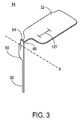
限定ではなく説明の目的で、本明細書に記載される挿入器は、図1に示されている例示的な検体モニタリングシステムと関連して用いられ得る。本明細書に記載される挿入器は、それ自体でまたはシステムと関連して、任意の医療用装置と共に用いられ得ることを理解されたい。図1は、本開示の複数の実施形態による例示的なインビボベースの検体モニタリングシステム100を示す。図示されるように、特定の実施形態では、検体モニタリングシステム100は身体装着用電子装置1100を含み、身体装着用電子装置1100は、インビボ検体センサ14(図1にはその近位部が示されている)に電気的に接続されると共に、ユーザの身体の皮膚表面への取り付けのために接着層218に取り付けられている。身体装着用電子装置1100は、内部区画を画成する身体装着用筐体122を含む。
In Vivo Monitoring System Embodiments For purposes of illustration and not limitation, the inserter described herein may be used in conjunction with the exemplary analyte monitoring system shown in FIG. It should be understood that the inserter described herein can be used with any medical device by itself or in conjunction with a system. FIG. 1 illustrates an exemplary in vivo-based
図1には、挿入装置200(または本明細書に記載される挿入装置300、400、2400、2500、2700、3700)も示されており、本明細書でより詳細に説明するように、挿入装置は、操作された際に、検体センサ14の一部分を、皮膚表面を通ってISFと流体接触するように経皮的に配置すると共に、身体装着用電子装置1100および接着層218を皮膚表面に配置する。特定の実施形態では、身体装着用電子装置1100、検体センサ14および接着層218は、使用前に挿入装置200の筐体内に密封されており、特定の実施形態では、接着層218も筐体内に密封されるか、または、接着層が装置の無菌状態を保つための密封を提供してもよい。挿入装置に関する更なる詳細は、例えば、米国特許出願第12/698,129号明細書、並びに米国特許仮出願第61/238,646号、同第61/246,825号、同第61/247,516号、同第61/249,535号および同第61/345,562号の各明細書で述べられており、それぞれの開示を参照してあらゆる目的で本明細書に組み込む。
Also shown in FIG. 1 is an insertion device 200 (or
図1に戻ると、検体モニタリングシステム100は表示装置1200を含み、表示装置1200は、ユーザに情報を出力するためのディスプレイ1220と、表示装置1200にデータやコマンドを入力するための、または別様で表示装置1200の動作を制御するための入力要素1210(例えば、ボタン、アクチュエータ、タッチセンサ式スイッチ、容量性スイッチ、感圧スイッチ、ジョグホイール等)とを含む。なお、幾つかの実施形態は、ディスプレイの無い装置、または、いかなるユーザインターフェイス要素も無い装置を含み得る。これらの装置には、データロガーとしてデータを格納し、且つ/または、身体装着用電子装置および/またはディスプレイの無い装置から、別の装置および/または場所にデータを転送するための導管を提供する機能が設けられ得る。本明細書には、例示の目的で、表示装置としての複数の実施形態を説明するが、それらが本開示の実施形態を限定することは決して意図されない。特定の実施形態においてはディスプレイの無い装置も用いられ得ることは自明である。
Returning to FIG. 1, the
特定の実施形態では、身体装着用電子装置1100は、モニタリング期間中に検体センサ14から受信した、モニタリングされた検体に関連するデータの一部または全てをメモリに格納し、使用期間が終わるまでメモリ内に維持するよう構成され得る。そのような実施形態では、格納されデータは、モニタリング期間の最後(例えば、身体装着用電子装置1100を、それがモニタリング期間中に配置された皮膚表面から取り外すことによって、検体センサ14をユーザから除去した後)に、身体装着用電子装置1100から取り出される。そのようなデータ記録構成においては、リアルタイムでモニタリングされた検体レベルは、モニタリング期間中に表示装置1200に通信または別様で身体装着用電子装置1100から送信されることはなく、モニタリング期間の後に身体装着用電子装置1100から取り出される。
In certain embodiments, the body-worn
特定の実施形態では、表示装置の1200の機能および動作が音声コマンドによって制御され得るように、表示装置1200の入力要素1210はマイクを含んでもよく、表示装置1200は、マイクから受信した音声入力を解析するよう構成されたソフトウェアを含んでもよい。特定の実施形態では、表示装置1200の出力要素は、情報を可聴信号として出力するためのスピーカを含む。身体装着用電子装置1100にも、スピーカ、マイク、および音声によって駆動される信号を生成、処理および格納するためのソフトウェアルーチン等の、音声に応答する類似の構成要素が設けられてもよい。
In certain embodiments, the
特定の実施形態では、ディスプレイ1220および入力要素1210は単一の構成要素(例えば、タッチスクリーン式ユーザインターフェイス等といった、ディスプレイ上での物理的な接触の存在および位置を検出できるディスプレイ)として一体化され得る。そのような実施形態では、ユーザは、ディスプレイを1回または2回叩くこと、ディスプレイ上で指または道具をドラッグすること、複数の指または道具を互いに向かって動かすこと、複数の指または道具を互いから離れるように動かすこと等を含むが、それらに限定されない、予めプログラムされた一組のモーションコマンドを用いて、表示装置1200の動作を制御してもよい。特定の実施形態では、ディスプレイは、LCD素子およびタッチセンサとして作用する単機能または二重機能の容量性素子を備えた画素領域を有するタッチスクリーンを含む。
In certain embodiments,
また、表示装置1200は、例えば遠隔端末(パーソナルコンピュータ)1700等の外部装置との有線データ通信のためのデータ通信ポート123を含む。データ通信ポート1230の例示的な実施形態は、USBポート、ミニUSBポート、RS−232ポート、Ethernet(登録商標)ポート、Firewire(登録商標)ポート、または適合するデータケーブルと接続するよう構成された他の類似のデータ通信ポートを含む。表示装置1200は、インビトロ血中グルコース測定を行うためにインビトログルコース試験紙を受け付けるインビトロ試験紙ポート1240を有する一体化されインビトログルコース計も含み得る。
The
引き続き図1を参照すると、特定の実施形態におけるディスプレイ1220は、様々な情報を表示するよう構成され、その一部または全ては、ディスプレイ1220上に同時にまたは異なるタイミングで表示され得る。特定の実施形態では、所与の表示画面に示される情報をユーザがカスタマイズできるように、表示される情報はユーザが選択可能である。ディスプレイ1220は、例えば、モニタリングされた期間にわたるグルコース値のグラフ出力を提供するグラフ表示1380(食事、運動、睡眠、心拍数、血圧等の重要なマーカーも示し得る)、例えば、モニタリングされたグルコース値(情報に対する要求に応答して取得または受信される)を提供する数値表示1320、および、例えば、ディスプレイ1220上で位置を移動することにより検体の変化率および/または検体の変化率の速度を示す動向または方向の矢印表示1310を含み得るが、それらに限定されない。
With continued reference to FIG. 1, the
図1に更に示されるように、ディスプレイ1220は、例えば、ユーザに日付情報を提供する日付表示1350、ユーザに時刻情報を提供する時刻情報表示1390、表示装置1200の電池(再充電可能または使い捨て)の状態をグラフで示す電池レベルインジケータ表示1330、例えば、周期的、定期的または所定数のユーザ較正事象が必要なモニタリングシステムにおいて、検体センサの較正が必要であることをユーザに通知するセンサ較正状態アイコン表示1340、音声/振動出力または警報の状態を表示する音声/振動設定アイコン表示1360、並びに、他の装置(身体装着用電子装置、データ処理モジュール1600、および/または遠隔端末1700等)との無線通信接続の表示を提供する無線接続性状態アイコン表示1370も含み得る。図1に更に示されるように、ディスプレイ1220は、メニューにアクセスするため、表示グラフ出力設定を変更するため、または別様で表示装置1200の動作を制御するための擬似タッチスクリーンボタン1250、1260を更に含み得る。
As further shown in FIG. 1, the
図1に戻ると、特定の実施形態では、表示装置1200のディスプレイ1220は、視覚的表示に加えてまたは視覚的表示の代わりに、警報通知(例えばグルコース値等の警報および/または警告通知等)を出力するよう構成され得る。警報通知は、可聴通知、触覚的通知、またはそれらの任意の組み合わせであり得る。1つの態様において、表示装置1200は、ディスプレイ1220上で提供される視覚的出力表示に加えて、ユーザに可聴出力表示および/または振動出力表示を提供するためのスピーカや振動出力要素等の他の出力要素を含み得る。更なる詳細及び他の表示の実施形態は、例えば、米国特許出願第12/871,901号明細書、並びに、米国特許仮出願第61/238,672号、同第61/247,541号および同第61/297,625号の各明細書に見出すことができ、それぞれの開示をあらゆる目的で参照して本明細書に組み込む。
Returning to FIG. 1, in certain embodiments, the
身体装着用電子装置1100が皮膚表面に配置され、且つ検体センサ14が生体内に配置されてISF(または他の適切な体液)との流体接触が確立された後、特定の実施形態における身体装着用電子装置1100は、身体装着用電子装置1100が表示装置1200からのコマンドまたは要求信号を受信した際、検体関連データ(例えば、モニタリングされた検体レベルに対応するデータ、モニタリングされた温度データ、および/または格納されている歴史的検体関連データ等)を無線で通信するよう構成される。特定の実施形態では、身体装着用電子装置1100は、表示装置1200が身体装着用電子装置1100からのデータブロードキャストの通信距離内にあるときに、表示装置1200によって受信されたモニタリングされた検体レベルと関連付けられたリアルタイムのデータを、少なくとも周期的にブロードキャストするよう構成され得る(即ち、情報を送信するために表示装置からのコマンドまたは要求を必要としない)。
Body wear in certain embodiments after body wear
例えば、表示装置1200は、身体装着用電子装置1100にデータ転送を開始するための1以上のコマンドを送信するよう構成され得る。それに応答して、身体装着用電子装置1100は、モニタリング期間中に収集された格納されている検体関連データを、表示装置1200に無線で送信するよう構成され得る。表示装置1200は、更に、パーソナルコンピュータ等の遠隔端末1700に接続されてもよく、格納されている検体レベル情報を身体装着用電子装置1100から遠隔端末1700に転送するためのデータの導管として機能する。特定の実施形態では、身体装着用電子装置1100から受信されたデータは、表示装置1200の1以上のメモリに(永久的にまたは一時的に)格納され得る。他の特定の実施形態では、表示装置1200は、身体装着用電子装置1100から受信したデータを表示装置1200に接続された遠隔端末1700に渡すためのデータの導管として構成される。
For example,
引き続き図1を参照すると、検体モニタリングシステム1000には、データ処理モジュール1600および遠隔端末1700も示されている。遠隔端末1700は、データの管理および解析、並びに検体モニタリングシステム1000の構成要素との通信のためのソフトウェアを含むパーソナルコンピュータ、サーバ端末、ラップトップコンピュータ、または他の適切なデータ処理装置を含み得る。例えば、遠隔端末1700は、遠隔端末1700と表示装置1200および/またはデータ処理モジュール1600との単方向または双方向データ通信のために、ローカルエリアネットワーク(LAN)、ワイドエリアネットワーク(WAN)、または他のデータネットワークに接続され得る。
With continued reference to FIG. 1, the
特定の実施形態における遠隔端末1700は、外科医のオフィスや病院に配置された1以上のコンピュータ端末を含み得る。例えば、遠隔端末1700は、表示装置1200の場所以外の場所に配置され得る。遠隔端末1700および表示装置1200は、それぞれ異なる部屋または異なる建物にあってもよい。遠隔端末1700および表示装置1200は、少なくとも約1マイル(約1.6キロメートル)離れていてもよい(例えば少なくとも約100マイル(約160キロメートル)離れていてもよく、例えば少なくとも約1000マイル(約1600キロメートル)離れていてもよい)。例えば、遠隔端末1700は表示装置1200と同じ市内にあってもよく、遠隔端末1700は表示装置1200と異なる市にあってもよく、遠隔端末1700は表示装置1200と同じ州内にあってもよく、遠隔端末1700は表示装置1200と異なる州にあってもよく、遠隔端末1700は表示装置1200と同じ国内にあってもよく、遠隔端末1700は表示装置1200と異なる国にあってもよい。
The remote terminal 1700 in certain embodiments may include one or more computer terminals located in a surgeon's office or hospital. For example, the
特定の実施形態では、検体モニタリングシステム1000には、データ処理モジュール1600等の別個の必要に応じて設けられるデータ通信/処理装置が設けられ得る。データ処理モジュール1600は、例えば、赤外線(IR)プロトコル、Bluetooth(登録商標)プロトコル、Zigbee(登録商標)プロトコルおよび802.11無線LANプロトコル等であるが、それらに限定されない1以上の無線通信プロトコルを用いて通信するための構成要素を含み得る。「Bluetooth」プロトコルおよび/または「Zigbee」プロトコルに基づくものを含む通信プロトコルの更なる説明は、米国特許出願公開第2006/0193375号明細書に見出すことができ、その内容をあらゆる目的で参照して本明細書に組み込む。データ処理モジュール1600は、1以上の表示装置1200、身体装着用電子装置1100、または遠隔端末1700との有線通信を確立するための、例えば、USBコネクタおよび/またはUSBポート、「Ethernet」コネクタおよび/またはポート、FireWireコネクタおよび/またはポート、またはRS−232ポートおよび/またはコネクタを含むがそれらに限定されない通信ポート、ドライバまたはコネクタを更に含み得る。
In certain embodiments, the
特定の実施形態では、データ処理モジュール1600は、身体装着用電子装置1100に所定の時間間隔(例えば、1分毎に1回、5分毎に1回等)でポーリングまたはクエリー信号を送信すると共に、それに応答して、身体装着用電子装置1100からモニタリングされた検体レベル情報を受信するようプログラムされる。データ処理モジュール1600は、そのメモリに受信した検体レベル情報を格納し、且つ/または、受信した情報を、表示装置1200等の別の装置に中継または再送信する。より具体的には、特定の実施形態において、データ処理モジュール1600は、身体装着用電子装置1100から受信した検体レベルデータを、表示装置1200若しくは遠隔端末(例えば、携帯電話ネットワークまたはWiFiデータネットワーク等のデータネットワークを介して)またはそれらの両方に再送信するまたは渡すためのデータ中継装置として構成され得る。
In certain embodiments, the
特定の実施形態では、身体装着用電子装置1100およびデータ処理モジュール1600は、身体装着用電子装置1100とデータ処理モジュール1600との間の周期的な通信が維持されるように、互いから所定の距離(例えば、約1〜12インチ、約1〜10インチ、約1〜7インチ、または約1〜5インチ(1インチは約2.54センチメートル))以内のユーザの皮膚表面に配置され得る。或いは、身体装着用電子装置1100とデータ処理モジュール1600との間の通信のための所望の距離が維持されるように、データ処理モジュール1600はユーザのベルトや衣服に装着されてもよい。更なる態様では、身体装着用電子装置1100およびデータ処理モジュール1600が単一のアセンブリとして組み合わされまたは一体化されて、皮膚表面に配置されるように、データ処理モジュール1600の筐体は、身体装着用電子装置1100と接続または係合するよう構成され得る。更なる実施形態では、データ処理モジュール1600は、身体装着用電子装置1100に取り外し可能に係合または接続され、これにより、データ処理モジュール1600が所望により必要に応じて取り外されまたは再取り付けされ得るようなモジュール性を更に提供する。
In certain embodiments, the body-worn
再び図1を参照すると、特定の実施形態において、データ処理モジュール1600は、所定の時間間隔(例えば毎分1回、5分毎に1回、30分毎に1回、または他の任意の適切な若しくは所望のプログラム可能な時間間隔等)で、身体装着用電子装置1100に、身体装着用電子装置1100からの検体関連データを要求するためのコマンドまたは信号を送信するようプログラムされる。データ処理モジュール1600が要求した検体関連データを受信すると、データ処理モジュール1600は受信したデータを格納する。このように、検体モニタリングシステム1000は、連続的にモニタリングされた検体関連情報を、プログラムされたまたはプログラム可能な時間間隔で受信するよう構成され得る。受信された検体関連情報は格納され且つ/またはユーザに対して表示される。データ処理モジュール1600に格納されたデータは、次に、治療に関する決定を改善するための次のデータ解析(例えば、モニタリング期間にわたる血糖レベルの偏位期間の頻度やモニタリング期間中に警報事象が生じた頻度の識別等)のために、表示装置1200や遠隔端末1700等に供給または送信され得る。この情報を用いて、医師、ヘルスケア提供者またはユーザは、食事、生活習慣および運動等の日課を調節し、またはそれらを修正することを推奨し得る。
Referring back to FIG. 1, in certain embodiments, the
別の実施形態では、データ処理モジュール1600は、身体装着用電子装置1100に、データ処理モジュール1600に設けられたスイッチのユーザによる作動または表示装置1200から受信したユーザ起動コマンドに応答して、検体関連データを受信するためのコマンドまたは信号を送信する。更なる実施形態では、データ処理モジュール1600は、所定の時間間隔の経過後にのみ、ユーザ起動コマンドの受信に応答して、身体装着用電子装置1100にコマンドまたは信号を送信するよう構成される。例えば、特定の実施形態では、ユーザが、プログラムされた期間内(例えば前回の通信から約5時間、前回の通信から10時間、または前回の通信から24時間等)に通信を開始しない場合には、データ処理モジュール1600は、身体装着用電子装置1100に要求コマンドまたは信号を自動的に送信するようプログラムされ得る。或いは、データ処理モジュール1600は、データ処理モジュール1600と身体装着用電子装置1100との間の前回の通信から所定の期間が経過したことをユーザに通知する警報を作動させるようプログラムされ得る。このように、ユーザまたはヘルスケア提供者は、ユーザが頻繁な検体レベル判定を維持し得るまたは行い得るように、データ処理モジュール1600を、検体モニタリングのレジメンとの一定の整合性を提供するようプログラムまたは設定し得る。
In another embodiment, the
特定の実施形態では、プログラムされたまたはプログラム可能な警報条件が検出された場合(例えば、検体センサ14によってモニタリングされた、検出されたグルコースレベルが、所定の許容可能範囲外にあり、医療処置または解析のための注意または介入を要する生理学的条件(例えば、低血糖条件、高血糖条件、切迫性高血糖条件または切迫性低血糖条件)を示す場合)には、適時に是正措置がとられ得るように、身体装着用電子装置1100の制御論理またはプロセッサによって1以上の出力表示が生成されて、身体装着用電子装置の1100ユーザインターフェイス上でユーザに対して出力され得る。それに加えてまたはその代わりに、表示装置1200が通信距離内にある場合には、出力表示または警報データは表示装置1200に通信されてもよく、警報データの受信が検出されると、表示装置1200のプロセッサがディスプレイ1220を制御して1以上の通知を出力する。
In certain embodiments, if a programmed or programmable alarm condition is detected (eg, the detected glucose level monitored by the
特定の実施形態では、身体装着用電子装置1100の制御論理またはマイクロプロセッサは、検体センサ14から得られた情報(例えば、現在の検体レベル、検体レベルの変化率、検体レベルの変化の加速、および/または、格納されているモニタリングされた検体データに基づいて決定され、モニタリングされた期間中の時間の関数としての検体レベルの変動の歴史的動向または方向を提供する検体動向情報)に基づいて、将来のまたは予期される検体レベルを決定するためのソフトウェアプログラムを含む。予報警報パラメータは、表示装置1200、身体装着用電子装置1100、またはそれらの両方においてプログラムされ得るかまたはプログラム可能であり、ユーザの検体レベルがその将来のレベルに達することが予想される前に、ユーザに対して出力され得る。これにより、適時な是正措置をとる機会がユーザに与えられる。
In certain embodiments, the control logic or microprocessor of body-worn
このような検体動向情報を与える、モニタリング期間にわたる時間の関数としてのモニタリングされた検体レベルの変化または変動等の情報は、例えば、表示装置1200、データ処理モジュール1600、遠隔端末1700および/または身体装着用電子装置1100の1以上の制御論理またはマイクロプロセッサによって決定され得る。そのような情報は、例えば、検体モニタリングシステム1000によって測定および予測された、現在の検体レベル、歴史的検体レベル、および/または予測される将来の検体レベルをユーザに対して示すグラフ(線グラフ等)として表示され得る。そのような情報は、方向を示す矢印(例えば、動向または方向を示す矢印表示1310を参照)または他のアイコン(例えば、画面上の基準点に対するそのアイコンの位置が、検体レベルの増減、並びに、検体レベルの増減の加速または減速を示す)としても表示され得る。この情報は、ユーザによって、検体レベルが許容可能範囲内および/または臨床的に安全な範囲内に留まることを確実にするために必要な何らかの是正措置を決定するために用いられ得る。他の視覚的インジケータ(例えば、色、フラッシュ、フェード等)、並びに、音声インジケータ(例えば、音声出力のピッチ、ボリューム若しくはトーンの変化等)および/または振動等の触覚インジケータも、モニタリングされた検体レベルの現在のレベル、方向、および/または変化率をユーザに通知する手段として、動向データの表示に組み込まれ得る。例えば、決定されたグルコースの変化率、プログラムされた臨床的に有意なグルコース閾値レベル(例えば、高血糖レベルおよび/または低血糖レベル)、およびインビボ検体センサによって得られた現在の検体レベルに基づき、システム1000は、臨床的に有意なレベルに達するまでにかかる時間を決定するためのコンピュータ可読媒体に格納されたアルゴリズムを含んでもよく、臨床的に有意なレベルに達する前に(例えば、臨床的に有意なレベルになることが予期される30分前、20分前、10分前、5分前、3分前、および/または1分前等)、通知を出力する(例えば出力の強度等を高めながら)。
Information such as changes or fluctuations in the monitored analyte level as a function of time over the monitoring period that provides such analyte trend information may be, for example,
再び図1に戻ると、特定の実施形態では、データ処理モジュール1600によって実行されるソフトウェアアルゴリズムは、外部メモリ装置(例えば、SDカード、マイクロSDカード、コンパクトフラッシュ(登録商標)カード、XDカード、メモリースティックカード、メモリースティックDuoカード、またはUSBメモリースティック/デバイス等)に格納され得る。そのような外部メモリ装置には、身体装着用電子装置1100、遠隔端末1700または表示装置1200の1以上にそれぞれ接続された際に実行される、実行可能なプログラムが格納される。更なる態様では、データ処理モジュール1600によって実行されるソフトウェアアルゴリズムは、携帯電話等の通信装置(例えば、WiFiまたはインターネットを使用可能なスマートフォンやパーソナルデジタルアシスタント(PDA)を含む)に、ダウンロードした通信装置によって実行されるダウンロード可能なアプリケーションとして供給され得る。
Returning again to FIG. 1, in certain embodiments, the software algorithms executed by the
スマートフォンの例としては、インターネット接続および/またはローカルエリアネットワーク(LAN)を介したデータ通信のためのデータネットワーク接続機能を有する、Windows(登録商標)、Android(商標)、iPhone(登録商標)オペレーティングシステム、Palm(登録商標)WebOS(商標)、Blackberry(登録商標)オペレーティンシステム、またはSymbian(登録商標)オペレーティンシステムに基づく携帯電話が挙げられる。上述のPDAとしては、例えば、1以上のマイクロプロセッサおよびデータ通信機能を有し、ユーザインターフェイス(例えば、ディスプレイ/出力部、および/または入力部)を有し、例えばデータ処理やインターネットを介したデータのアップロード/ダウンロードを行うよう構成された携帯電子装置が挙げられる。そのような実施形態では、遠隔端末1700は、上述の通信装置の1以上に、その装置と遠隔端末1700との通信が確立された際に、実行可能なアプリケーションソフトウェアを提供するよう構成され得る。
Examples of smart phones include Windows (registered trademark), Android (trademark), and iPhone (registered trademark) operating systems having a data network connection function for data communication via the Internet connection and / or a local area network (LAN). , Palm (R) WebOS (TM), Blackberry (R) operating system, or Symbian (R) operating system. The PDA described above has, for example, one or more microprocessors and a data communication function, and has a user interface (for example, a display / output unit and / or an input unit), for example, data processing or data via the Internet. Mobile electronic devices configured to upload / download. In such an embodiment,
更なる実施形態では、遠隔端末1700への有線接続が必要ないように、実行可能なソフトウェアアプリケーションは、無線(OTA:over-the-air)でOTAダウンロードとして提供され得る。例えば、実行可能なアプリケーションは、ソフトウェアダウンロードとして通信装置に自動的にダウンロードされ、通信装置の設定に応じて、自動的に用いるために、または通信装置上でのアプリケーションのインストールの実行に対するユーザによる確認または承認に基づき、装置にインストールされ得る。ソフトウェアのOTAダウンロードおよびインストールは、データ処理モジュール1600のおよび/または表示装置1200の既存の機能または特徴に対する更新またはアップグレードであるソフトウェアアプリケーションおよび/またはルーチンを含み得る。
In further embodiments, the executable software application may be provided as an OTA download over the air (OTA) so that a wired connection to the
図1の遠隔端末1700に戻ると、特定の実施形態では、遠隔端末1700と表示装置1200および/またはデータ処理モジュール1600との通信が確立された際に、遠隔端末1700によって、特に、表示装置1200、身体装着用電子装置1100および/またはデータ処理モジュール1600用の、新たなソフトウェアおよび/またはソフトウェアの更新(ソフトウェアのパッチや修正等)、ファームウェアの更新またはソフトウェアドライバのアップグレードが提供され得る。例えば、身体装着用電子装置1100用のソフトウェアのアップグレード、実行可能なプログラミングの変更または修正は、表示装置1200またはデータ処理モジュール1600の1以上によって遠隔端末1700から受信され、その後、身体装着用電子装置1100のソフトウェアまたはプログラム可能な機能を更新するために身体装着用電子装置1100に供給されてもよい。例えば、特定の実施形態では、身体装着用電子装置1100で受信されてインストールされるソフトウェアは、ソフトウェアのバグの修正、以前にインストールされたソフトウェアのパラメータの修正(特に、検体関連データの格納時間間隔の修正、身体装着用電子装置1100の時間基準または情報の再設定または調節、送信されるデータタイプ、データ伝送シーケンス、またはデータ格納期間の修正)を含み得る。携帯電子装置のソフトウェアのフィールドアップグレード性およびデータ処理の更なる詳細は、米国特許出願第12/698,124号、同第12/794,721号、同第12/699,653号および同第12/699,844号の各明細書、並びに米国特許仮出願第61,359,265号および同第61/325,155号の各明細書に記載されており、それらの開示をあらゆる目的で参照して本明細書に組み込む。
Returning to the
センサ
検体測定システム100の検体センサ14は、様々な検体のレベルをモニタリングするために用いられ得る。例えば、モニタリングされ得る検体としては、アセチルコリン、アミラーゼ、ビリルビン、コレステロール、絨毛性ゴナドトロピン、クレアチンキナーゼ(例えば、CK−MB)、クレアチン、DNA、フルクトサミン、グルコース、グルタミン、成長ホルモン、ホルモン、ケトン、乳酸、酸素、過酸化物、前立腺特異抗原、プロトロンビン、RNA、甲状腺刺激ホルモンおよびトロポニンが挙げられるが、これらに限定されない。例えば、抗生物質(例えば、ゲンタマイシン、バンコマイシン等)、ジギトキシン、ジゴキシン、乱用薬物、テオフィリンおよびワルファリン等の薬剤の濃度もモニタリングされ得る。所与のセンサによって1以上の検体がモニタリングされ得る。2以上の検体をモニタリングするこれらの実施形態では、それらの検体は、同じ身体装着用電子装置を(例えば同時に)用いてまたは異なる身体装着用電子装置を用いて、同時にまたは異なるタイミングでモニタリングされ得る。
Sensor The
本開示の一実施形態では、センサ14は、検体レベルがモニタリングされるユーザの身体内または身体上に物理的に配置される。センサ14は、ユーザの検体レベルを連続的にサンプリングし、サンプリングされた検体レベル(例えば、グルコース濃度)を、身体装着用電子装置に入力するための対応するデータ信号(例えば、電流または電圧)に変換するよう構成され得る。或いは、センサ14は、オン・デマンドで検体レベルをサンプリングするよう構成され得る。身体装着用電子装置は、センサによって供給された信号を、増幅、フィルタリング、平均化および/または別様で処理し得る。
In one embodiment of the present disclosure, the
センサ14の一実施形態が図2に示されている。本明細書に記載される挿入器は、他の医療用装置と共に使用できることを理解されたい。本明細書に記載される形状は単に例示的なものである。他のセンサ形状も考えられる。幾つかの実施形態では、センサ14は、誘電体(例えば、ポリエステルやポリアミド等のポリマーやプラスチック材料)である基体を含む。この実施形態では、センサは、一部が皮膚の下に、一部が皮膚の上に配置可能に構成される。従って、センサ14は、挿入部または内部30と、外部または電気的接触部32とを含む。幾つかの実施形態では、接触部32は、例えば、身体装着用電子装置1100における他の電子装置に接続するための複数の導電性の接点36、38および40(本明細書では3つの接点として示されている)を含む。(図1を参照。)この実施形態で設けられる接点は、作用電極用、参照電極用および対電極用である。幾つかの実施形態では、2以上の作用電極が設けられる。これらの電極の動作的な部分、即ち、作用電極、参照電極および対電極(個々には示さず)は、挿入部(例えば挿入部30の遠位端、例えば部分34)に設けられる。幾つかの実施形態では、1以上の電極が身体の外にあり得る(例えば、外部対電極)。接点および電極の動作的な部分は、基体の表面に設けられた回路配線42、44および46によって接続される。幾つかの実施形態では、配線はチャネル内に設けられるか、または基体内に埋め込まれてもよく、または基体のそれぞれ異なる面を横断してもよい。導電性の接点、導電性の配線および電極は、白金、パラジウム、金、炭素等の導電材料で作られる。所与のセンサには2以上の材料が用いられ得る。センサの更なる詳細は、例えば、米国特許第6,175,572号および同第6,103,033号の各明細書に記載されており、それらを参照してあらゆる目的で本明細書に組み込む。
One embodiment of
センサ14は、近位保持部48を含み得る。挿入部30および近位保持部48のサイズは、本明細書で説明されるように、被験者の皮膚内への設置のための鋭利部材と共に配置されるよう構成される。使用中には、センサ14は(例えば、線Bに沿って)曲がって、略垂直に交差する2つの面内に配置されるよう構成され得る。そのような曲げは、以下に説明するように、身体装着用電子装置と接続される前にまたは接続中に生じ得る。(図17を参照)。
The
部分48および52は、センサの近位部と遠位部との間の電気的接続のための経路(例えば、導電性の配線)を提供する。センサ14には、更に、切欠54が設けられる。そのような構成により、図3に示されるように、保持部48が直立の状態に留まり、略垂直に交差する2つの面内に配置されるように、センサ14を(例えば、線Bで示されている線に沿って)曲げるのが容易になる。後述するように、センサ14の固定および配置を補助するために、センサタブ50は身体装着用筐体122内に収容され得る。近位保持部48は、挿入用の鋭利部材内に配置されるよう、近位保持部48と挿入部30との長手方向の位置合わせを維持する。
化学的検出層が適用された電極の構成を介して、検体を特定した酸化酵素によって触媒される検体の酸化還元反応の量に比例した(検体濃度を示す)電流を発生することにより、電気化学的に動作する検体センサの実施形態を本明細書に記載した。これらの反応を生じさせてそのレベルを検出するために設けられる電極の数が、2つ、3つ、またはより多数である実施形態が存在する。しかし、本明細書に記載されるように、他のタイプのセンサが用いられてもよい。 Through an electrode configuration to which a chemical detection layer has been applied, an electrochemical current is generated (indicating analyte concentration) proportional to the amount of analyte redox reaction catalyzed by the analyte-specific oxidase, thereby allowing electrochemical Embodiments of an analyte sensor that operate in an automated manner have been described herein. There are embodiments in which the number of electrodes provided to generate these reactions and detect their levels is two, three, or more. However, other types of sensors may be used as described herein.
センサ14の一部分は皮膚の表面より上に配置されてもよく、遠位部30が皮膚を突き通って皮下のスペースに入り、ユーザの生体液(例えばISF等)と接触する。センサ14の電気化学に関する更なる詳細は、米国特許第5,264,104号、同第5,356,786号、同第5,262,035号、同第5,320,725号および同第6,990,366号の各明細書に記載されており、それぞれを参照してあらゆる目的で本明細書に組み込む。
A portion of the
幾つかの実施形態では、センサは、生体液内に存在する検体と接触してモニタリングするために、使用期間(例えば、1分間以上、少なくとも1日以上、約1日〜約30日間、若しくはそれ以上、約3日間〜約14日間、約3日間〜約7日間、または幾つかの実施形態では、数週間までのより長い期間)にわたって、被験者の身体に埋め込み可能である。これに関して、センサは、被験者の様々な部位(例えば、腹部、上腕、腿等)に配設され得る(例えば、筋肉内に、経皮的に、血管内に、または体腔内に)。 In some embodiments, the sensor is used for a period of use (eg, 1 minute or more, at least 1 day or more, about 1 day to about 30 days, or more, for monitoring in contact with an analyte present in the biological fluid. As such, it can be implanted into the subject's body for about 3 days to about 14 days, about 3 days to about 7 days, or in some embodiments, longer periods up to several weeks). In this regard, sensors can be placed at various locations (eg, abdomen, upper arm, thighs, etc.) of the subject (eg, intramuscularly, percutaneously, within a blood vessel, or within a body cavity).
幾つかの実施形態では、センサ14は、何らかの試用期間にわたってユーザの身体に挿入され且つ/または埋め込まれることによって用いられる。そのような実施形態では、基体は比較的柔軟な材料で形成され得る。
In some embodiments, the
図2〜図3に示されている実施形態は3つの電極を有するが、他の実施形態は、より少ないまたはより多い電極を含み得る。例えば、2つの電極のセンサが用いられ得る。センサ14は、外部から電力供給されて、存在する検体の量に比例する電流を通してもよい。或いは、幾つかの実施形態では、センサ14自体が電流源として作用し得る。2つの電極の幾つかの実施形態では、センサは自己バイアス型であってもよく、この場合、参照電極は必要無い。例示的な電源内蔵式の2つの電極のセンサは、2009年2月26日に出願された「電源内蔵式検体センサ(Self-Powered Analyte Sensor)」という名称の米国特許出願第12/393,921号明細書に記載されており、それを参照してあらゆる目的で本明細書に組み込む。特定の実施形態では、電源内蔵式センサによって供給される電流のレベルは、例えば、ナノアンペア台の低いものであり得る。
Although the embodiment shown in FIGS. 2-3 has three electrodes, other embodiments may include fewer or more electrodes. For example, a two-electrode sensor can be used. The
挿入アセンブリ
被験者に医療用装置を設置するために用いられる挿入アセンブリが提供される。幾つかの実施形態では、挿入アセンブリは、挿入器および医療用装置を含む。挿入器は、被験者に、例えば、検体センサ、輸液セットまたはカニューレ等の様々な医療用装置を挿入するよう構成され得る。幾つかの実施形態では、挿入器は、そのような装置の組み合わせ(例えば、組み合わされたセンサ/輸液セット等)を同じまたは異なるタイミングで、同じまたは異なる位置に設置するよう構成され得る。例えば、特定の実施形態では、所与の挿入器は、第1の装置および第2の装置を異なるタイミングで設置するよう構成され得る。これに関して、挿入器は再使用可能であり得る。例えば、挿入器は、例えば、アダプタを取り付けることにより、且つ/または挿入器の一部分を取り外すことにより、2以上の医療用装置(2以上のタイプの医療用装置を含む)と共に用いられるよう変更可能であり得る。挿入器は、被験者の皮膚の下にまたは皮膚を通して医療用装置を設置できるか、または、医療用装置を皮膚の表面に配置できる。医療用装置は、挿入後に装置を皮膚に対して適切な位置に維持するための、例えば、棘状部、タブ、接着剤等の特徴または構造を有し得る。挿入装置は、例えば、医療用装置を挿入または設置せずに皮膚を突き通すためのランセットとしても用いられ得る。
Insertion assembly An insertion assembly is provided for use in installing a medical device on a subject. In some embodiments, the insertion assembly includes an inserter and a medical device. The inserter can be configured to insert various medical devices, such as, for example, an analyte sensor, an infusion set or a cannula, into the subject. In some embodiments, the inserter may be configured to place such device combinations (eg, combined sensor / infusion set, etc.) at the same or different locations at the same or different times. For example, in certain embodiments, a given inserter may be configured to install the first device and the second device at different times. In this regard, the inserter may be reusable. For example, the inserter can be modified for use with more than one medical device (including more than one type of medical device), eg, by attaching an adapter and / or removing a portion of the inserter It can be. The inserter can place the medical device under or through the subject's skin, or the medical device can be placed on the surface of the skin. The medical device may have features or structures, such as barbs, tabs, adhesives, etc., for maintaining the device in place with respect to the skin after insertion. The insertion device can also be used, for example, as a lancet for piercing the skin without inserting or installing a medical device.
幾つかの実施形態では、挿入アセンブリは、挿入器、検体センサおよび電源を含む。電源は、挿入器によって検体センサと同時に挿入され得る。他の実施形態では、電池は、検体センサの挿入前または挿入後に設置される。そのような場合には、電源は挿入器によってまたは別個に適用され得る。電源は、センサに電流もしくは電位を提供するために、且つ/またはモニタユニットへの1以上の信号の通信ための電力を提供するために用いられ得る。 In some embodiments, the insertion assembly includes an inserter, an analyte sensor, and a power source. The power source can be inserted simultaneously with the analyte sensor by the inserter. In other embodiments, the battery is installed before or after insertion of the analyte sensor. In such cases, the power source can be applied by an inserter or separately. The power source may be used to provide a current or potential to the sensor and / or to provide power for communication of one or more signals to the monitor unit.
幾つかの実施形態では、挿入アセンブリは、挿入器、検体センサ等の医療用装置、および身体装着用電子装置を含む。身体装着用電子装置は、挿入器によって検体センサと同時に配置および/または設置され得る。他の実施形態では、身体装着用電子装置は、検体センサの設置前または設置後に設置される。例えば、検体センサは挿入器によって設置されてもよく、身体装着用電子装置はその後に設置されてもよい。 In some embodiments, the insertion assembly includes an inserter, a medical device such as an analyte sensor, and a body worn electronic device. The body-worn electronic device can be placed and / or placed at the same time as the analyte sensor by the inserter. In other embodiments, the body-mounted electronic device is installed before or after the analyte sensor is installed. For example, the analyte sensor may be installed by an inserter and the body-worn electronic device may be installed thereafter.
幾つかの実施形態では、身体装着用電子装置は、検体センサに電圧または電流を提供する。幾つかの実施形態では、身体装着用電子装置は、検体センサによって供給された信号を処理する。更なる実施形態では、身体装着用電子装置は、検体センサによって更なる構成要素(例えば、モニタユニット、コンピュータまたは他の構成要素等)に供給された信号に関連する信号を供給するための通信機能を含み得る。幾つかの実施形態では、RFIDアンテナ等の通信回路が設けられる。電源は、これらの機能の一部または全てに電力を供給するために用いられ得る。幾つかの実施形態では、モニタユニットから、例えば誘導結合を介して電力が供給される。 In some embodiments, the body-worn electronic device provides a voltage or current to the analyte sensor. In some embodiments, the body-worn electronic device processes the signal provided by the analyte sensor. In a further embodiment, the body-worn electronic device is a communication function for providing a signal related to a signal provided by the analyte sensor to a further component (eg, a monitor unit, a computer or other component, etc.). Can be included. In some embodiments, a communication circuit such as an RFID antenna is provided. A power supply can be used to power some or all of these functions. In some embodiments, power is supplied from the monitor unit, for example via inductive coupling.
挿入器は、複数の異なる構成要素を含み得る。例えば、挿入器は、鋭利部材を被験者の皮膚に向かって前進させるための1以上の構成要素を含み得る。センサおよび身体装着用電子装置は、キャリッジ等の支持構造によって支持され得る。鋭利部材および/または検体センサ/支持構造を前進させるための駆動器が設けられ得る。幾つかの実施形態では、アクチュエータは、直接または間接的に鋭利部材および/または支持構造に接続されており、ユーザによってアクチュエータに加えられた手の力が鋭利部材および/または支持構造に伝えられるようになっている。幾つかの実施形態では、加えられた力によって、鋭利部材および/または支持構造は、(挿入器内の)後退位置と(被験者の皮膚に向かう)前進位置との間で駆動される。幾つかの実施形態では、センサおよび身体装着用電子装置は、設置前には、シースから内側に延出する突起と接触することによって後退位置に維持される。この実施形態によれば、センサおよび身体装着用電子装置は、一時的に、支持構造とシースの内壁に配設された突起との間で動作可能に維持される。 The inserter can include a plurality of different components. For example, the inserter may include one or more components for advancing the sharp member toward the subject's skin. The sensor and the body-mounted electronic device can be supported by a support structure such as a carriage. A driver for advancing the sharp member and / or the analyte sensor / support structure may be provided. In some embodiments, the actuator is directly or indirectly connected to the sharp member and / or support structure such that a hand force applied to the actuator by a user is transmitted to the sharp member and / or support structure. It has become. In some embodiments, the applied force drives the sharp member and / or support structure between a retracted position (within the inserter) and an advanced position (towards the subject's skin). In some embodiments, the sensor and the body-worn electronic device are maintained in a retracted position by contact with a protrusion that extends inwardly from the sheath prior to installation. According to this embodiment, the sensor and the body-worn electronic device are temporarily maintained operatively between the support structure and the protrusion disposed on the inner wall of the sheath.
また、挿入器は、検体センサおよび必要に応じて身体装着用電子装置を被験者上に留まらせつつ、鋭利部材を後退させるための1以上の構成要素を含み得る。鋭利部材を後退させるための構成要素は、リトラクタを含み得る。リトラクタとアクチュエータとは同じ構造であってもよく、または、幾つかの共通の構成要素を含んでもよいことを理解されたい。幾つかの実施形態では、リトラクタは、直接または間接的に鋭利部材に接続されており、ユーザによって加えられた手の力がリトラクタから鋭利部材に伝えられて鋭利部材を皮膚から後退させるようになっている。他の実施形態では、鋭利部材を後退させるための駆動アセンブリが設けられ得る。例えば、駆動アセンブリは、鋭利部材を被験者の皮膚から離れる方向に後退させるためのばね、モータ、油圧ピストン等を含み得る。駆動アセンブリはリニア駆動要素も含み得る。 The inserter may also include one or more components for retracting the sharp member while the analyte sensor and optionally the body-worn electronic device remain on the subject. The component for retracting the sharp member may include a retractor. It should be understood that the retractor and the actuator may be the same structure or may include several common components. In some embodiments, the retractor is connected directly or indirectly to the sharp member so that hand force applied by the user is transmitted from the retractor to the sharp member, causing the sharp member to retract from the skin. ing. In other embodiments, a drive assembly for retracting the sharp member may be provided. For example, the drive assembly may include a spring, motor, hydraulic piston, and the like for retracting the sharp member away from the subject's skin. The drive assembly may also include a linear drive element.
幾つかの実施形態では、リトラクタは、ユーザによって作動されると、鋭利部材を引き抜く。そのような場合には、ユーザは、鋭利部材を引き抜くことを所望するときにリトラクタを作動させる。例えば、リトラクタは、解放スイッチを含み得る。解放スイッチが作動されると、駆動アセンブリ(例えば、ばねまたは他の駆動器)は、鋭利部材を皮膚から後退させる。他の実施形態では、リトラクタおよびアクチュエータは、共通の構成要素を含む。鋭利部材および検体センサを前進させるためにアクチュエータが作動された後、ユーザはアクチュエータを解放し、これにより、駆動アセンブリが皮膚から鋭利部材を引き抜く。 In some embodiments, the retractor pulls the sharp member when activated by the user. In such a case, the user activates the retractor when it is desired to pull out the sharp member. For example, the retractor can include a release switch. When the release switch is activated, a drive assembly (eg, a spring or other driver) retracts the sharp member from the skin. In other embodiments, the retractor and actuator include common components. After the actuator is actuated to advance the sharp member and analyte sensor, the user releases the actuator, which causes the drive assembly to withdraw the sharp member from the skin.
幾つかの実施形態では、リトラクタは、挿入の作動後、ユーザが更に介入することなく、鋭利部材を引き抜く。例えば、挿入器は、鋭利部材および支持構造が所定の量だけ前進すると鋭利部材を自動的に後退させる特徴または構成要素を含み得る。挿入後に鋭利部材の引き抜きを開始するためのユーザによる更なる動作が必要ない挿入装置を、鋭利部材の「自動」引き抜きを有するものとして参照する。 In some embodiments, the retractor removes the sharp member after the actuation of the insertion without further user intervention. For example, the inserter may include features or components that automatically retract the sharp member when the sharp member and the support structure are advanced a predetermined amount. An insertion device that does not require further action by the user to initiate withdrawal of the sharp member after insertion is referred to as having "automatic" withdrawal of the sharp member.
挿入装置
挿入器用の針ハブの一実施形態が図4〜図5に示されている。針ハブ136は、尖った遠位部160を有する鋭利部材124を支持する。本明細書で述べるように、幾つかの実施形態では、鋭利部材124の壁の少なくとも一部分に、長手方向の壁開口部または間隙162が設けられる。間隙162の長さNは、センサ14の近位保持部48まで至る挿入部30の長さと一致するよう選択され、特定の実施形態では約3mm〜約50mm(例えば、約5mm、約10mm、約15mmまたは約20mm)であり得る。鋭利部材124の長さLは、約3mm〜約50mm(例えば、5mm以上、約10mm、約20mm、約30mmまたは約50mm)であり得、センサの挿入部30の長さおよびセンサ14の挿入部30の所望の深さに基づいて選択される。幾つかの実施形態では、間隙の2つの縁部間の距離または離間は約0.2mm〜約0.5mm(例えば、約0.22mm、約0.25mm等)である。
Insertion Device One embodiment of a needle hub for an inserter is shown in FIGS.
図6〜図8には、鋭利部材124の遠位部160がより詳細に示されている。図6に示されるように、この実施形態では、鋭利部材124は略C字またはU字形状のプロファイルを有するが、例えば、略V字形状等の他の構成を有してもよい。鋭利部材124の壁の中には長手方向の間隙162が設けられる。図7には、角度のついた先端部が設けられた遠位部160が示されている。幾つかの実施形態では、角度のついた先端部には、第1の角度のついた先端部分164と、第2の鋭角の先端部分166とが設けられ得る。複数のエッジおよび面を含む例示的な構成は、突き通す力、被験者の外傷および出血を低減するための鋭利な先端を提供する。センサ本体の遠位部の幅は、約20ゲージ未満から約26ゲージまで(例えば、21ゲージ〜約25ゲージ)の直径を有する挿入用の鋭利部材124の切欠162内に嵌るサイズであり、特定の実施形態では、鋭利部材は21ゲージ、23ゲージまたは25ゲージである。そのような鋭利部材は、少なくとも鋭利部材によって担持される部分の幅または直径が約0.20mm〜約0.80mm(例えば、約0.25mm〜約0.60mm)であるセンサと共に用いられ得る。幾つかの実施形態では、センサの少なくとも一部分の幅または直径は0.27mm、0.33mmまたは0.58mmである。幾つかの実施形態では、鋭利部材224は金属薄板で作られ、断面が略V字、U字またはC字構成になるよう折り曲げられる。鋭利部材124を構成する折り曲げられた金属薄板を製造するために、様々な技術を用いることができる。例えば、エッチングされた金属薄板の技術を用いて、鋭利部材124を構成できる。このようにして、挿入中に皮膚に突き通る際の痛みが軽減されるように、非常に鋭利なエッジを有する鋭利部材を形成することができる。他の実施形態では、図9に示されるような鋭利なエッジを有する複雑な金属薄板の形状を形成するために、順送り型技術が用いられ得る。幾つかの実施形態では、挿入器の組立プロセス中に鋭利部材を扱えるように、鋭利部材124はプラスチックキャップと共に成型され得る。更に、V字、U字またはC字形状の金属薄板構成を補強するために、ダイカットされた鋭利部材をプラスチックと共に成型してもよい。更に、他の実施形態では、レーザカットされた鋭利部材が形成され得る。このように、レーザを用いて、壁開口部または間隙162、並びに第1の角度のついた先端部分164および第2の鋭角の先端部分166を形成できる。
6-8 show the
別の実施形態では、鋭利部材124は、図10に示されている方法を用いて、標準的な皮下注射針から形成され得る。まず、(円形の断面を有する)皮下注射針を、鋭利部材124の所望の長さに切断する。次に、皮下注射針を圧縮して、断面を円形の形状から楕円形状に永久的に変形させる。次に、皮下注射針の先端部を斜めに研磨して、上述のように突き通すために必要な力を低減するために、鋭利な先端部を作る。最後に、適切な技術(例えば、研磨、電解研磨等)によって針の上部を除去する。得られた鋭利部材124はU字形状の構成を有し、センサ14の挿入のために十分な空間を提供する。幾つかの実施形態では、先端部研磨工程および圧縮工程は逆の順序で行われ得る。
In another embodiment, the
圧縮工程に起因して、ユーザは、まず、より大きい直径の皮下注射針から開始して、仕上がった鋭利部材124が上述の鋭利部材と同様の寸法を有するようにしてもよい。
Due to the compression process, the user may first start with a larger diameter hypodermic needle so that the finished
図11〜図12は、針ハブ136および鋭利部材124に対する身体装着用筐体122の位置を示す。身体装着用筐体122は、センサ14の少なくとも一部分およびセンサ制御ユニット12を保持するよう構成され得る。図11に示されるように、鋭利部材124は、身体装着用筐体122のアパチャー168を通って延びる。従って、幾つかの実施形態では、鋭利部材124は、身体装着用筐体122に連結されない。センサ14の遠位部は、鋭利部材124内に配置される。更に図12に示されるように、身体装着用筐体122内には、センサ制御ユニット12の電子装置80(例えば、身体装着用ユニット16の電子装置要素を含むプリント基板)およびセンサハブ123が配置される。センサ14は、センサハブ123のタブ129等の配置部材を受容する配置構造またはスリット127を含み得る。電池(例えば、使い捨て電池または再充電可能電池)等の電源82が設けられる。幾つかの実施形態では、電源82は、センサに電位または電流を供給するために用いられる。パッシブRFID等の受動的な通信プロトコルが用いられる実施形態では、通信用の電源は設けられない。そのような電力は、モニタユニット18によって供給される。1以上の信号を送信するためにセンサ制御ユニットが用いられる幾つかの実施形態では、そのような通信回路用の電力を供給するために1以上の電源が用いられ得る。幾つかの実施形態では、電池の有効作動寿命は、センサ14の有効作動寿命を超え得る。
FIGS. 11-12 show the position of the
図13は、図13〜図17に示されている挿入器500等の挿入器の鋭利部材124に対する身体装着用筐体122の向きを断面で示している。本明細書で述べるように、幾つかの実施形態では、センサ14は略曲がった構成で配設され、センサの一部(例えば、挿入部30および近位保持部48)が略垂直になるように(即ち、挿入器の長手方向の軸と略位置合わせされ且つ皮膚表面に対して略垂直になるように)なっており、接触部32(輪郭で示されている)は略水平の構成に配向されて、回路80等のデータ処理装置の電子装置と電気的に接触する。センサタブ50は、身体装着用筐体122のプラスチックに封入されて(「オーバーモールドされて」)適切な位置に固定され得る。切欠56は、例えば、センサタブ50が身体装着用筐体122の材料によって封入されるのを可能にすることにより、センサ14に更なる安定性を提供し、更に、身体装着用筐体122の垂直な目印に対して切欠56を垂直に配置可能にすることにより、取り付け中にセンサ14を垂直に配向する手段を提供する。
FIG. 13 shows in cross section the orientation of the body-worn
身体装着用筐体122と共に取り付けられるセンサ14は、キャリッジ130の凹面状の窪み等のキャリッジ130の窪み内に配置され得る。或いは、身体装着用筐体122と共に取り付けられるセンサ14は、支持構造とシースの壁から延出する1以上の突起との間に配置され得る。更に別の代替例では、身体装着用筐体122と共に取り付けられるセンサ14は、鋭利部材124との解除可能な締まり嵌め結合によって適切な位置に保持され得る。このように、キャリッジは、センサ筐体と共に取り付けられるセンサが配置される窪みを有する必要はない。挿入器の初期構成では、鋭利部材124は、キャリッジ130に形成された長手方向のアパチャー168を通って延びる。幾つかの実施形態では、アパチャー168は、鋭利部材124および針ハブ136がキャリッジ130と接触しないような適切なサイズを有する。従って、一方では針ハブ136(および鋭利部材124)が、他方ではキャリッジ130(図13)および身体装着用筐体122が、互いに独立して同時に移動する。他の実施形態では、アパチャーと鋭利部材との締り嵌めが設けられ得る。
The
センサ14の挿入部30および近位保持部48は、鋭利部材124の長手方向の穴162(例えば、図6を参照)内に配設される。近位保持部48は鋭利部材124の長手方向の穴内に配設され、鋭利部材124内へのセンサ14の取り付けに対して更なる安定性を提供する。鋭利部材124の長手方向の壁間隙または開口部162は、センサ14と位置合わせされ、タブ50および接触部32が鋭利部材124から側方外側に延出するようになっている。
The
図14〜図17には挿入器の実施形態が示されており、挿入器500として示されている。幾つかの実施形態では、挿入器500の最大直径は約30mm〜約60mm(例えば、約40mm、約43mm、約43.5mm、約50.5mm、約54.5mm等)である。幾つかの実施形態では、挿入器500の最大高さは約40mm〜約80mm(例えば、約44mm、約46mm、約50mm、約53mm、約67mm、約71mm等)である。幾つかの実施形態では、挿入器500の体積は約35cm3〜約110cm3(例えば、約40cm3、約41cm3、約50cm3、約60cm3、約61cm3、約62cm3、約69cm3、約70cm3、約79cm3、約90cm3、約106cm3等)である。最大高さは、アクチュエータ514からシース542の遠位面512まで測定される。体積は、蛇腹部502および蛇腹部502から突出するシース542の部分として測定される。
An embodiment of an inserter is shown in FIGS. 14-17 and is shown as
挿入器500は、蛇腹部502と、シース542と、中に収容されている医療用装置および鋭利部材の滅菌環境を維持するための取り外し可能な遠位キャップ504とを含む。図15に示されるように、シース542から取り外された遠位キャップ504が示されている。シース542は、被験者の皮膚上への配置のための遠位面512を画成する。挿入器500は、医療用装置を被験者の皮膚内に前進させるために用いられ得る。幾つかの実施形態では、医療用装置を被験者の皮膚内に前進させるために、蛇腹部502が圧縮される。蛇腹部502は、立ち上がった部分516および畳まれた部分518を含む一連の同心の襞を含む。
The
図16には、キャップ504を取り外す前の使用前の挿入器500が断面で示されており、キャップ504は、シースのねじ山510とキャップ504のねじ山との相互係合によってシース542に取り付けられている。キャップ504は乾燥剤タブレット590を含む。キャップ504は、使用前のシース542内における鋭利部材524の位置を維持するための受容部を更に含み得る。
FIG. 16 shows in cross-section the
図16に示されるように、挿入器500の初期構成において、蛇腹部502は弛緩した伸張位置に配設される。そのような構成では、鋭利部材524は接着層518のアパチャー520から離間した位置に配設される。蛇腹部502の近位端部は、ボタンまたはアクチュエータ部514を含む。アクチュエータ部514から遠位に向かって、側壁528および針ハブ536が延びている。アクチュエータ部514に下向きの力が加えられると、(側壁528への結合を介して)針ハブ536およびキャリッジ530に下向きの力が加えられる。キャリッジ530は、身体装着用筐体122を受容するための窪み532を含む。更に、キャリッジ530は、横方向に作用するスプリングアームを含む。スプリングアームは、挿入の完了時に、身体装着用筐体122の外周にある戻り止め要素と係合して、身体装着用筐体122を容易に解放できるようにする。鋭利部材524は、挿入器500内において針ハブ536から長手方向に延出する。幾つかの実施形態では、鋭利部材は皮膚表面に対して斜めの角度(約0°と90°との間)で支持される。
As shown in FIG. 16, in the initial configuration of the
図17は、挿入中の挿入器500を断面で示している。蛇腹部502が、ばねの付勢546に逆らってシース542に対して押下されると、キャリッジ530および鋭利部材524が近位位置から遠位位置へと長手方向に遠位へと移動する。そのような下方向の近位への移動中に、ばね546は、アクチュエータ514に隣接した上部(近位部)とシース542に隣接した下部(遠位部)との間で圧縮される。鋭利部材524が遠位へと付勢されると、鋭利部材524はセンサ14のセンサ挿入部30(図12)を被験者の皮膚Sの皮下部分に運ぶ。幾つかの実施形態では、キャリッジ530とシース542との間に接着層を用いて、接着結合を破ってキャリッジの遠位への移動を生じさせるためにユーザが最小限の力の閾値を超えることを要求してもよい。
FIG. 17 shows in cross section the
アクチュエータ部514に加えられた下向きの力を取り除くと、ばねの付勢546によって上向きの(近位への)力が与えられ、これにより、鋭利部材524が被験者の皮膚Sから引き抜かれる。幾つかの実施形態では、蛇腹部502によって、鋭利部材524を皮膚Sから引き抜くための上向きの(近位への)力が全て提供されてもよい。
When the downward force applied to the
図18〜図24には例示的な駆動装置が示されており、駆動装置3600として示されている。本明細書に記載される駆動装置3600(並びに駆動装置3700、3800、3900および4000)は、本明細書に記載される任意の挿入器(例えば、挿入器500(図14〜図17を参照)或いは挿入器2400(図44〜図58を参照)等)と共に用いられるよう設計されていることを理解されたい。更に、特定の実施形態では、駆動装置3600(並びに3700、3800、3900および4000)は、医療用装置を少なくとも部分的に患者の皮膚内へと前進させるためのアクチュエータボタンまたは駆動器を含む任意の挿入装置と共に用いられるよう構成され得る。従って、挿入器500と協働する駆動装置3600(および3700)が示されているが、そのような装置の組み合わせは、駆動装置と挿入器との全ての組み合わせを包含することを意図しないことを理解されたい。同様に、駆動装置3900(および4000)は挿入器2400と共に示されているが、そのような装置の組み合わせは、駆動装置と挿入器との全ての組み合わせを包含することを意図しないことを理解されたい。例えば、本明細書に開示される駆動装置は、様々な機能の中で、特に「ボタンを押す」機能を提供する(この機能において、駆動装置が取り付けられた挿入器のアクチュエータボタンまたは駆動器に駆動装置が接続され得る)。
An exemplary drive device is shown in FIGS. 18-24 and is shown as
本明細書に記載される駆動装置のもう一つの特徴はモジュール性である。幾つかの実施形態では、駆動装置と挿入器とはそれぞれ独立して動作可能であり得る。例えば、挿入器は、駆動装置を使用せずに医療用装置を患者の皮膚内へと前進させるためのアクチュエータボタンまたはスイッチを含み得る。駆動装置は、作動機能を提供する限りにおいて、駆動装置の駆動器が接触し得る作動ボタンを有する任意の挿入器と共に用いられ得る。幾つかの実施形態では、モジュール性により、駆動装置を複数回用いられるよう設計でき、挿入装置を使い捨てにできる。他の実施形態では、例えば、使用毎にセンサおよび/または身体装着用筐体を交換することにより、挿入器も複数回用いることが可能である。 Another feature of the drive described herein is modularity. In some embodiments, the drive and the inserter can each be independently operable. For example, the inserter may include an actuator button or switch for advancing the medical device into the patient's skin without using a drive. The drive can be used with any inserter having an activation button that can be contacted by the driver of the drive as long as it provides an activation function. In some embodiments, modularity allows the drive device to be designed to be used multiple times and allows the insertion device to be disposable. In other embodiments, the inserter can be used multiple times, for example by replacing the sensor and / or body-worn housing with each use.
駆動装置3600は、挿入器に対する位置決めのための筐体3602を含む。筐体3602に対して長手方向に移動可能な負荷要素3604が設けられる。幾つかの実施形態では、挿入器を自動的に作動させるアクチュエータ(例えば、回転カム3606)を有する駆動装置3600が設けられる。使用においては、安全解除ボタン3620が(矢印Eの方向に)押されて、ラック3610をピニオン3612(図18)と接続させる。図18に示されるように、安全解除ボタン3620が押され、負荷要素3604が下に向かって(矢印Dの方向に)押下されると、カム3606が、ねじりばね3614の付勢に逆らって第1の方向Fに回転する。リリースボタン3618は、押されるまで、ばねを負荷された位置に維持する。
The
図20に示されるように、駆動装置3600が挿入器500に対して配置される。図20〜図24には挿入器500が示されているが、任意の挿入器が駆動装置3600と共に用いられ得ることを理解されたい。幾つかの実施形態では、筐体3602の寸法並びに、カム3606の位置および形状は、挿入器の寸法と相互作用するよう選択される。例えば、筐体3602は、挿入器500のシース542と協働してスナップ嵌めまたは締り嵌めされるよう設計され得る。
As shown in FIG. 20, the
図21に示されるように、挿入器500のキャップ504が取り外され(図示せず)、それにより、被験者の皮膚上への接着部518(図示せず)の配置が可能になる。鋭利部材524(図示せず)を挿入するために、リリースボタン3618が押され得る(矢印H)。
As shown in FIG. 21, the
図22〜図24は、鋭利部材524を被験者の皮膚内に駆動するための駆動装置3600の一連の動きを示す。図22に示されるように、リリースボタン3618が押されると、ねじりばね3614が解放され、それにより、ねじりばね3614の付勢によって方向Jへのカム3606の回転が駆動される。カム3606は、突起3607を有する表面を含む。図23に示されるように、カム3606が更に回転すると、突起3607が挿入器500のアクチュエータボタン514と係合する。その結果、蛇腹部502およびばね546が圧縮され、針ハブ536およびキャリッジ530が遠位へと前進する(被験者の皮膚に向かって下に。図22〜図24には図示せず。例えば、図16を参照)。内部にセンサ14を収容している鋭利部材524は被験者の皮膚内へと駆動され、身体装着用筐体122は接着部518(図示せず)に接着される。ねじりばねの巻きが更に戻ると、カム3606が更に回転し、その結果、図24に示されるように、突起3607がアクチュエータボタン514から離間する。その結果、後退ばね546(図示せず)の付勢により蛇腹部502が伸張した構成に戻り、鋭利部材524を被験者の皮膚から後退させて、少なくとも部分的に皮膚に埋め込まれたセンサを残す。
22-24 show a series of movements of the
図25〜図31には、挿入器の作動のための別の例示的な駆動装置が示されており、駆動装置3700として示されている。幾つかの実施形態では、駆動装置3700は再使用可能な装置であり、一方、挿入器は使い捨ての装置であり得る。駆動装置3700は駆動装置3600と略同一であり、ここでは実質的な違いを述べると共に添付の図面に示す。
FIGS. 25-31 show another exemplary drive for actuation of the inserter, shown as
図25および図26に示されるように、駆動装置3700は、挿入器に対する配置のための筐体3702を含む。上部筐体3705に対して長手方向に移動可能な負荷要素3704が設けられる。幾つかの実施形態では、アクチュエータ3706は、挿入器を自動的に作動させる往復動要素である。使用において、負荷要素3704は、駆動ばね3714の通常の付勢に逆らって、軌道3710に沿って横方向(矢印Kの方向)に進められる。駆動ばね3714が負荷されると、係止機構3718がばね3714を負荷状態に維持する。
As shown in FIGS. 25 and 26, the
図27に示されるように、駆動装置3700が挿入器500に対して配置される。図27〜図31には挿入器500が示されているが、任意の挿入器が駆動装置3700と共に用いられ得ることを理解されたい。図28に示されるように、挿入器500のキャップ504が取り外され(図示せず)、それにより、被験者の皮膚上への接着部518(図示せず)の配置が可能になる。鋭利部材524(図示せず)を挿入するために、リリースボタン3618が押され得る(矢印L)。
As shown in FIG. 27, the
図29〜図31は、鋭利部材524を被験者の皮膚内に駆動するための駆動装置3700の一連の動きを示す(図16を参照)。図29〜図31に示されるように、リリースボタン3718が押下されると、駆動ばね3714が解放され、それにより、ばね3714の付勢によってスライド部材3707が方向Mに駆動される。スライド部材3707は、軌道3710内に配置されることにより、横方向の移動に制限される。同様に、アクチュエータ3706は、軌道3709内に配置されることにより、長手方向の移動に制限される。スライド部材3707は、クランク部材3720によってアクチュエータ3706に接続される。クランク部材3720はスライド部材3707の一端部に回動可能に接続されると共に、他端部がアクチュエータ3706に接続される。図30に示されるように、スライド部材3707が更に横方向に移動すると、アクチュエータ3706が遠位へと前進して挿入器500のアクチュエータボタン514と係合する。その結果、蛇腹部502(図示せず)が圧縮され、針ハブ536およびキャリッジ530遠位へと前進し、それにより鋭利部材524を被験者の皮膚内へと駆動すると共に、身体装着用筐体122(図16を参照)を接着部518(図示せず)に接着する。接着部518については例えば図16を参照。図31に示されるように、スライド部材3707が更に横方向に移動すると、アクチュエータ3706は近位に進む。その結果、後退ばね546(例えば図16を参照)の付勢により蛇腹部502が伸張した構成に戻り、鋭利部材524を被験者の皮膚から後退させる。
29-31 show a series of movements of a
図32〜図43には、挿入器の作動のための駆動装置が示されており、駆動装置3800として示されている。幾つかの実施形態では、駆動装置3800は再使用可能な装置であり、一方、挿入器は本明細書に記載した挿入器500であり得る。駆動装置3800はアクチュエータ3600および3700と略同一であり、ここでは実質的な違いを述べると共に添付の図面に示す。
In FIGS. 32 to 43, a drive device for the operation of the inserter is shown, shown as
図32および図33に示されるように、駆動装置3800は、本明細書に記載した挿入器500等の挿入器に対する配置のための筐体3802を含む。筐体3802に対して長手方向に移動可能な負荷要素3804が設けられる。負荷要素が押下されると、ロータ3808がねじりばね(図示せず)の付勢に逆らって回転する。係止要素(図示せず)が、ねじりばねを負荷状態に維持する。
As shown in FIGS. 32 and 33, the
図34〜図43には、駆動装置3800の作動が強調されて図示されている。図34に示されるように、駆動装置3800は、トリガ3810と、カム3808と、安全解除ボタン3812と、ねじりばね3814と、軸3816と、爪3818と、アクチュエータ3806と、戻しばね3820とを含む。駆動装置3800を安全解除するために、負荷要素3804(図示せず)が押されると、安全解除ボタン3812が押下されて軸3816を回し、それによりねじりばね3814(図35)が巻かれる。爪3818は軸3816を適切な位置に係止する(図36)。ユーザが負荷要素3804を押下した後、安全解除ボタン3812は元の位置に戻り、一方、軸3816は爪3818(図37)によって適切な位置に保持される。
34 to 43 show the operation of the
駆動装置3800を作動させるために、ユーザは再び負荷要素3804を押す。これにより、トリガ3810が下に移動し、カム3808が解放される。幾つかの実施形態では、代わりに、負荷要素3804は、安全解除ボタン3812およびトリガ3810を押下するために用いられる。そして、カム3808は、ねじりばね3814(図38)によって前方に駆動される。幾つかの実施形態では、第1の負荷要素を用いて安全解除ボタン3812を押下し、第2の負荷要素を用いてトリガ3810を押下する(図示せず)。
To activate the
カム3808が回転すると、カム3808はアクチュエータ3806を押し下げる(図39〜図40)。このストロークの最後に、僅かなドウェルがある。これにより、センサ本体が保持されて、皮膚接着パッチに押し付けられる(図41)。図43に示されるように、カム3808は完全に一回転した後、トリガ3810によって止められる。戻しばね3820がアクチュエータ3806を押し上げ、挿入器にかかっている圧力を解除する。被験者がトリガ3810を解放すると、カム3808はホームポジションに至るまで回転を続け、それにより、駆動装置3800が再使用可能になる(図43)。
When the
引き続き図33を参照すると、挿入器500は、身体装着用筐体122およびセンサ14を支持している。鋭利部材(図示せず)を用いて、センサを患者の皮膚内に前進させる。アクチュエータ3806は挿入器500のアクチュエータ114(アクチュエータ514と略同一)と接触して、鋭利部材およびセンサを下方向に被験者の皮膚に向かって駆動する。
With continued reference to FIG. 33, the
図44には、別の例示的な実施形態による挿入器2400が示されている。幾つかの実施形態では、挿入器2400の最大直径は約30mm〜約60mm(例えば、約40mm、約43mm、約43.5mm、約50.5mm、約54.5mm等)である。幾つかの実施形態では、挿入器2400の最大高さは約40mm〜約80mm(例えば、約44mm、約46mm、約50mm、約53mm、約67mm、約71mm等)である。幾つかの実施形態では、挿入器2400の体積は約35cm3〜約110cm3(例えば、約40cm3、約41cm3、約50cm3、約60cm3、約61cm3、約62cm3、約69cm3、約70cm3、約79cm3、約90cm3、約106cm3等)である。最大高さは、筐体2402の上部から筐体2402の底部まで測定される。体積は、筐体部分2402の体積として測定される。
FIG. 44 illustrates an
図44を参照すると、挿入器2400は、筐体2402と、中に収容されている医療用装置および鋭利部材を保護するための取り外し可能な遠位キャップ2412とを含む。筐体2402および遠位キャップ2412は、金属、プラスチック等の任意の適切な材料で製造され得る。幾つかの実施形態では、キャップ2412は、ポリマーまたはプラスチック材料で製造され得る。
Referring to FIG. 44, the
図45には、挿入器2400の構成要素の分解図が示されている。図示されるように、完全に組み立てられたときに、挿入器2400は一般的に、プランジャ2405と、ばね2406と、筐体2402と、鋭利部材2404と、身体装着用筐体122と、鋭利部材保持部2408と、接着パッチ218と、キャップ2412とを含む。
In FIG. 45, an exploded view of the components of the
図46には、鋭利部材保持部2408のより詳細な図が示されている。鋭利部材保持部2408は、挿入器2400内において鋭利部材2404を鋭利部材保持部2408に対して決まった位置に保持し、それにより、後の使用において、鋭利部材2404が安全に被験者の皮膚に突き通るようにする。
In FIG. 46, a more detailed view of the sharp
挿入器2400を組み立てるために、図47に示されるように、鋭利部材2404が身体装着用筐体122の開口部を通して挿入される。鋭利部材保持部2408は、鋭利部材2404が身体装着用筐体122を通って完全に挿入されるのを防止する。幾つかの実施形態では、身体装着用筐体122は検体センサ14とセンサ制御ユニット12とを含む。
To assemble the
次に、図48〜図50に示されるように、プランジャ2405、ばね2406および筐体2402が組み立てられる。プランジャ2405は、ばね2406の中心を通って挿入されるばね保持部材を含む。組み立てられると(図44)、プランジャ2405のリップ部2414は筐体2402の内壁2416(図示せず)と係合する。これにより、ばね2406が筐体部材2402のリップ部2418とプランジャ2405の底面2424(図示せず)との間に収容される。得られた挿入器2400のサブアセンブリにより、プランジャ2405は、ばね2406が完全に伸張した近位位置と、底面2424が筐体2402の壁2426と係合する遠位位置との間を移動可能になる。
Next, as shown in FIGS. 48 to 50, the
次に、図47に示されているセンサ筐体アセンブリが、図48〜図50に示されている挿入器サブアセンブリに挿入される。図50に示されるように、身体装着用筐体122は、鋭利部材2404の先端がプランジャ2405とは反対側を向いた状態で、筐体2402に挿入される。得られたアセンブリが図51に示されている。図44に示されるように、鋭利部材保持部2408の溝がプランジャ2405のタブ2422(図示せず)と係合する。身体装着用筐体122は、筐体アーム戻り止め要素2440(図示せず)によって筐体2402内において軸方向に保持される。
Next, the sensor housing assembly shown in FIG. 47 is inserted into the inserter subassembly shown in FIGS. As shown in FIG. 50, the body-mounted
最後に、図52に示されるように、接着パッチ218が筐体2402の開口部を覆うよう配置され、キャップ2412が筐体2402にスナップ嵌めされる。完全に組み立てられた挿入器2400が図53に示されている。幾つかの実施形態では、接着パッド218は両面に接着材料を有する。接着パッド218には、鋭利部材2404を被験者の皮膚内に配置可能にする中心アパチャー220が設けられ得る。挿入中に、鋭利部材2404はアパチャー220を通って被験者の皮膚に入り、少なくともセンサを運ぶ。
Finally, as shown in FIG. 52, the
図54は、遠位キャップ2412が取り外された後の、使用前の初期構成の挿入器2400を断面で示す。図示されるように、鋭利部材2404は挿入器2400内において長手方向に延びている。幾つかの実施形態では、鋭利部材2404は、皮膚表面に対して斜めの角度(例えば、約0°と90°との間)で支持される。
FIG. 54 shows in cross-section the
幾つかの実施形態では、鋭利部材2404は中実の針である。幾つかの実施形態では、鋭利部材2404には、内部の穴を画成する略円筒状構成(例えば、剛性の円筒状部材または皮下注射型の針)が設けられる。鋭利部材2404には、壁に細長い長手方向の開口部または間隙も設けられ得る。幾つかの実施形態では、鋭利部材2404は金属薄板から作られ、断面で略V字、U字またはC字構成になるよう折り曲げられて、長手方向の窪みを画成する。
In some embodiments, the
プランジャ2405の押下により、身体装着用筐体122および鋭利部材2404が、近位位置から遠位位置へと長手方向に遠位へと移動する。そのような下方向の遠位への移動中に、ばね2406は、リップ部2418と底面2424との間で更に圧縮される。戻り止め2440は、身体装着用筐体122が下方向の遠位への移動を継続するために凌駕すべき最小限の力の閾値を設ける。最小限の力の閾値を超えると、戻り止め2440は身体装着用筐体122によって外に向かって押され、身体装着用筐体122は傾斜路2442上に移動する。身体装着用筐体122と筐体の傾斜路2442との間の摩擦により、身体装着用筐体122がプランジャ2405に接触して保持される。
Depressing the
図55に示されるように、プランジャ2405の押下により、挿入器2400が初期構成から配置構成へと前進する。プランジャ2405の押下中にプランジャ2405とハブ2408とが接触すると、下向きの力が加えられ、その結果、鋭利部材2404が遠位へと移動する。鋭利部材2404が遠位へと付勢されると、鋭利部材2404はセンサ挿入部30を被験者の皮膚S(図示せず)の皮下部分内に運ぶ。プランジャ2405の押下中にプランジャ2405と身体装着用筐体122とが接触すると、下向きの力が加えられ、その結果、身体装着用筐体122が遠位へと移動する。プランジャ2405のリップ部2414は、遠位への移動中、身体装着筐体122を被験者の皮膚Sに対して平行に維持する。
As shown in FIG. 55, pressing the
図56に示されるように、プランジャ2405が遠位位置に到達すると、底面2424が壁2426と係合して、更なる下への移動を防止する。身体装着用筐体122の遠位面(下面)が接着パッド218の上面と係合し、それにより被験者の皮膚表面Sに接着される。
As shown in FIG. 56, when
被験者または何らかの装置がプランジャ2405から力を解放すると、図57に示されるように、被験者の皮膚表面Sに接着した身体装着用筐体122を残して、ばね2406はプランジャ2405を近位位置へと付勢する。鋭利部材2404が身体装着用筐体122を通って引き抜かれる間、タブ2427(図示せず)は身体装着用筐体122に更なる力を与えて、身体装着用筐体122を接着パッチ218に対して保持するのを補助する。図58に示されるように、最後的に、ばね2406によって及ぼされる上向きの力により、挿入器2400は初期構成に戻る。
When the subject or any device releases the force from the
幾つかの実施形態では、図59に示されるように、挿入器2400は、滅菌パッケージ2480に入った状態で配布され得る。この構成の挿入器2400を用いるために、ユーザは、まず、皮膚の挿入部位をアルコールで清浄にする。次に、ステップ1に示されるように、被験者は、滅菌パッケージ2480から挿入器2400を取り出す。次に、ステップ2〜ステップ3に示されるように、被験者は、挿入器を挿入部位に配置して、身体装着用筐体122が被験者の皮膚に接着されるまで、プランジャ2405を押下する。次に、被験者はプランジャ2405を解放する。最後に、被験者は挿入器2400を挿入部位から取り除いて、挿入器を廃棄する。
In some embodiments, as shown in FIG. 59, the
別の実施形態では、図60に示されるように、図59に示されている滅菌された挿入器2400は、駆動装置3900(図61〜図79)と共に用いられ得る。このように、センサ筐体ユニットの挿入は半自動化され、これはより一環したユーザ経験をもたらし得ると共に、ユーザエラーのリスクを低減し得る。図61〜図79には例示的な駆動装置が示されており、駆動装置3900として示されている。
In another embodiment, as shown in FIG. 60, the sterilized
駆動装置3900は、挿入器に対する配置のための筐体3902を含む。筐体3902に対して長手方向に移動可能なリリースボタン3904が設けられる。図62〜図65に示されるように、戻しばね3906によって及ぼされる力により、リリースボタン3904は近位位置と遠位位置との間を移動可能である。
The
図61に示されるように、駆動装置3900が挿入器2400に対して配置される。挿入器2400は図44〜図60に示されているが、任意の挿入器が駆動装置3900と共に用いられ得ることを理解されたい。駆動装置3900および適切な挿入器はモジュール式であり得るので、筐体3902の寸法並びにリリースボタン3904の位置および形状は、挿入器の寸法と相互作用するよう選択される。例えば、筐体3902は、挿入器2400のシース2402と協働してスナップ嵌めまたは締り嵌めされるよう設計され得る。
As shown in FIG. 61, a
図62〜図65は、鋭利部材2404を被験者の皮膚内に駆動するための駆動装置3900の一連の動きを示す。図62は、発射前の駆動装置3900を示す。図示されるように、駆動装置3900は、筐体3902と、リリースボタン3904と、戻しばね3906と、駆動ばね3908と、プランジャ3910とを含む。図67〜図69には、筐体3902、プランジャ3910、リリースボタン3904の3次元の斜視図がそれぞれ示されている。リリースボタン3904はタブ3912を含む。タブ3912は、筐体3902のリップ部3914と係合して、戻しばね3906の上向きの力がリリースボタン3904と筐体3902(図66を参照)とを外すのを防止する。リリースボタン3904は突起3918も含む。
62-65 show a series of movements of the
プランジャ3910は、プランジャ3910を筐体3902に拘束するタブ3916(図示せず)を含む。リリースボタン3904の底部とプランジャ3910の上部との間には、駆動ばね3908が配設される。或いは、駆動ばね3908は図示されているプランジャ3910の柱の周囲にあって、ボタン3904のシリンダ部によって圧縮されてもよい。
図63に示されるように、リリースボタン3904が筐体3902に向かって押下されると、戻しばね3906および駆動ばね3908が圧縮される。同時に、突起3918によってタブ3916が筐体3902から外れる。これにより、図64に示されるように、駆動ばね3908がプランジャ3910を挿入器3900に向かって前進させる。内部にセンサを収容している鋭利部材2404が被験者の皮膚内へと駆動され、身体装着用筐体122が接着パッド118に接着される。
As shown in FIG. 63, when the
被験者がボタン3904にかかっていた圧力を解放すると、戻しばね3906がボタン3904を初期位置に押し戻す。ボタン3904が戻ると、ボタンのアームがプランジャ3910のアームを初期位置に引き戻し、自動的にタブ3916を筐体3902と再係合させる(図65)。センサは被験者の皮膚に挿入された状態に留まる。
When the subject releases the pressure applied to
図70〜図79には例示的な駆動装置が示されており、駆動装置4000として示されている。
An exemplary drive device is shown in FIGS. 70-79 and is shown as
駆動装置4000は、挿入器に対する配置のための筐体4004を含む。筐体4004に対して長手方向に移動可能な外部ボタン4002が設けられる。図73〜図79に示されるように、筐体4004と外部ボタン4002との間に配置された戻しばね(図示せず)によって及ぼされる力により、外部ボタン4002は近位位置と遠位位置との間を移動可能である。
図70に示されるように、駆動装置4000が挿入器2400の上に配置される。挿入器2400は図44〜図58に示されているが、任意の挿入器が駆動装置4000と共に用いられ得ることを理解されたい。駆動装置4000および適切な挿入器はモジュール式であり得るので、筐体4004の寸法並びにカムリリースボタン3904の位置および形状は、挿入器の寸法と相互作用するよう選択される。例えば、筐体4004は、挿入器2400のシースと協働してスナップ嵌めまたは締り嵌めされるよう設計され得る。
As shown in FIG. 70, the
図71は、駆動装置4000の構成要素の分解図を示す。図示されるように、駆動装置4000は、外部ボタン4002と、戻しばね4006と、内部ボタン4008と、筐体4004と、駆動ばね4010と、プランジャ4012とを含む。組み立てられ駆動装置4000が図72に示されており、明確のために一部の構成要素は部分的に透明に示されている。
FIG. 71 shows an exploded view of the components of
図73〜図79は、鋭利部材2404を被験者の皮膚内に駆動するための駆動装置4000の一連の動きを示す。図73は、発射前の駆動装置4000を示す。組み立てられると、戻しばね4006は外部ボタン4002と筐体4004との間に封入される。同様に、駆動ばね4010は、内部ボタン4008の底部とプランジャ4012上の表面4020との間に封入される。
73-79 show a series of movements of the
外部ボタン4002は、タブ4022を用いて内部ボタン4008を適切な位置に係止するガイド4013を含む。内部ボタン4008は、外部ボタン4002を筐体4004に対して移動可能にするレール4015を含む。
プランジャ4012は、内部ボタン4008内に嵌って保持されるタブ4014を含む。更に、プランジャ4012は、筐体4004のレッジ部4017と係合する開口部を有する付属部4018を有するアーム4016を含む。
駆動装置4000を作動させるために、被験者は外部ボタン4002を被験者の皮膚の方向に押下して、図75に示されるように、戻しばね4006および駆動ばね4010を圧縮する。最終的に、図76に示されるように、内部ボタン4008に配置されたタブ4019が付属部4018をレッジ部4017から押しのける。
To activate the
付属部4018がレッジ部から変位されると、図76に示されるように、駆動ばね4010がプランジャ4012を挿入器2400のプランジャ2405に向かって駆動可能になる。最終的に、図77に示されるように、鋭利部材2404が被験者の皮膚内に駆動され、身体装着用筐体122が被験者に接着される。挿入器2400が存在しない場合には、プランジャは最終的に、プランジャアームがレッジ部4017と係合したとき、またはタブ4014が内部ボタン4008と係合したときに、前進を止める。
When the
鋭利部材2404を被験者の皮膚から取り除くために、被験者は、図78に示されるように、外部ボタン4002から圧力を除去して、戻しばね4006が外部ボタン4002に上向きの圧力を及ぼすようにしなければならない。ガイド4013が、レール4015を介して内部ボタンを引き上げる。内部ボタン4008はタブ4014によってプランジャ4012を引き上げる。プランジャ4008は、付属部4018をレッジ部4017に再係合するのに十分な距離だけ引き上げられる。これにより、更なる工程を行わずに、挿入器が即座に再使用できるようになる。同時に、挿入器2400内に配置された戻しばねが、鋭利部材2404を被験者の皮膚から後退させる。図79に示されるように、戻しばね4006は最終的に、駆動装置4000を元の構成に戻す。
In order to remove the
本明細書に記載された主題は、記載された具体的な実施形態に限定されず、当然ながら様々なものであり得ることを理解されたい。また、本明細書で用いられる用語は、具体的な実施形態を説明することのみを目的とするものであり、本主題の範囲を限定することは意図されず、本主題の範囲は添付の特許請求の範囲によってのみ限定されるものであることを理解されたい。 It should be understood that the subject matter described herein is not limited to the specific embodiments described, but can of course vary. Also, the terminology used herein is for the purpose of describing particular embodiments only and is not intended to limit the scope of the present subject matter, which is intended to It should be understood that it is limited only by the scope of the claims.
14 検体センサ
122 身体装着用筐体
124、524、2404 鋭利部材
130、530 キャリッジ
136、536 針ハブ
162 壁開口部または間隙(長手方向の穴)
200、500、2400 挿入器
502 蛇腹部
512 遠位面
514 アクチュエータ
542、2402 シース
2402 筐体
2405 プランジャ
2406 ばね
2408 鋭利部材保持部
3600、3700、3800、3900、4000 駆動装置
3602、3702、3802、3902、4004 筐体
3606、3808 回転カム
3614、3814 ねじりばね
3706、3806 アクチュエータ
3714、3908、4010 駆動ばね
3618、3718、3904 リリースボタン
3707 スライド部材
3720 クランク部材
3804 負荷要素
3810 トリガ
3910、4012 プランジャ
4002 外部ボタン
4008 内部ボタン
14
200, 500, 2400
Claims (19)
該装置は第1のサブアセンブリと第2のサブアセンブリとを備え、
前記第1のサブアセンブリは、
前記被験者の皮膚上への配置のための遠位面を画成するシースと、
近位位置と遠位位置との間を移動可能なハンドルと、
前記医療用装置を支持する装置支持部であって、該装置支持部を通るアパチャーを画成し、前記ハンドルに接続された装置支持部と、
前記アパチャーを通って延びる鋭利部材を支持する鋭利部材支持部であって、前記装置支持部に接続された鋭利部材支持部と、
前記鋭利部材支持部を前記近位位置に向かって付勢する第1の駆動器と、
を含み、
前記第2のサブアセンブリは、
前記第1のサブアセンブリに取り外し可能に取り付けられるよう構成された筐体と、
前記鋭利部材支持部を前記遠位位置に向かって前進させる第2の駆動器と、
を含むことを特徴とする装置。 A device for inserting a medical device at least partially through the skin of a subject,
The apparatus comprises a first subassembly and a second subassembly,
The first subassembly comprises:
A sheath defining a distal surface for placement on the subject's skin;
A handle movable between a proximal position and a distal position;
A device support for supporting the medical device, defining an aperture through the device support, and connected to the handle;
A sharp member support that supports a sharp member extending through the aperture, the sharp member support connected to the device support;
A first driver that biases the sharp member support toward the proximal position;
Including
The second subassembly includes
A housing configured to be removably attached to the first subassembly;
A second driver for advancing the sharp member support toward the distal position;
The apparatus characterized by including.
該装置は第1のサブアセンブリと第2のサブアセンブリとを備え、
前記第1のサブアセンブリは、
前記被験者の皮膚上への配置のための遠位面を画成するシースと、
近位位置と遠位位置との間を移動可能なハンドルと、
前記医療用装置を支持する装置支持部であって、前記ハンドルの遠位への移動に応答して前記シースに対して近位位置と遠位位置との間を移動可能な装置支持部と、
鋭利部材を支持する鋭利部材支持部であって、前記ハンドルの遠位への移動に応答して前記シースに対して近位位置と遠位位置との間を移動可能な鋭利部材支持部と、
前記鋭利部材支持部を前記近位位置に向かって付勢する第1の駆動器と、
を含み、
前記第2のサブアセンブリは、
前記第1のサブアセンブリに取り外し可能に取り付けられるよう構成された筐体と、
前記筐体に対して遠位へと移動するよう構成されたアクチュエータであって、該アクチュエータが所定の位置に到達したときに解放部材が作動されるアクチュエータと、
前記ハンドルを前記遠位位置に向かって前進させる第2の駆動器と、
を含み、
前記解放部材が作動されると付勢部材が解放されることを特徴とする装置。 A device for inserting a medical device at least partially through the skin of a subject,
The apparatus comprises a first subassembly and a second subassembly,
The first subassembly comprises:
A sheath defining a distal surface for placement on the subject's skin;
A handle movable between a proximal position and a distal position;
A device support for supporting the medical device, wherein the device support is movable between a proximal position and a distal position relative to the sheath in response to distal movement of the handle;
A sharp member support for supporting a sharp member, wherein the sharp member support is movable between a proximal position and a distal position relative to the sheath in response to distal movement of the handle;
A first driver that biases the sharp member support toward the proximal position;
Including
The second subassembly includes
A housing configured to be removably attached to the first subassembly;
An actuator configured to move distally with respect to the housing, wherein the release member is actuated when the actuator reaches a predetermined position;
A second driver for advancing the handle toward the distal position;
Including
The apparatus of claim 1, wherein the biasing member is released when the release member is actuated.
Applications Claiming Priority (9)
| Application Number | Priority Date | Filing Date | Title |
|---|---|---|---|
| US31724310P | 2010-03-24 | 2010-03-24 | |
| US61/317,243 | 2010-03-24 | ||
| US34556210P | 2010-05-17 | 2010-05-17 | |
| US61/345,562 | 2010-05-17 | ||
| US36137410P | 2010-07-02 | 2010-07-02 | |
| US61/361,374 | 2010-07-02 | ||
| US41126210P | 2010-11-08 | 2010-11-08 | |
| US61/411,262 | 2010-11-08 | ||
| PCT/US2011/029883 WO2011162843A1 (en) | 2010-03-24 | 2011-03-24 | Medical device inserters and processes of inserting and using medical devices |
Related Child Applications (1)
| Application Number | Title | Priority Date | Filing Date |
|---|---|---|---|
| JP2016115095A Division JP2016187574A (en) | 2010-03-24 | 2016-06-09 | Medical device inserters and devices provided with medical devices |
Publications (2)
| Publication Number | Publication Date |
|---|---|
| JP2013523217A true JP2013523217A (en) | 2013-06-17 |
| JP2013523217A5 JP2013523217A5 (en) | 2014-05-08 |
Family
ID=44673643
Family Applications (4)
| Application Number | Title | Priority Date | Filing Date |
|---|---|---|---|
| JP2013501502A Active JP5904500B2 (en) | 2010-03-24 | 2011-03-24 | Apparatus and system for inserting sharp member under skin surface |
| JP2013501503A Pending JP2013523217A (en) | 2010-03-24 | 2011-03-24 | Medical device inserter and method for inserting and using medical device |
| JP2016044196A Pending JP2016128031A (en) | 2010-03-24 | 2016-03-08 | System for engaging inserter to analyte monitoring device and method for engaging inserter to analyte monitoring device |
| JP2016115095A Pending JP2016187574A (en) | 2010-03-24 | 2016-06-09 | Medical device inserters and devices provided with medical devices |
Family Applications Before (1)
| Application Number | Title | Priority Date | Filing Date |
|---|---|---|---|
| JP2013501502A Active JP5904500B2 (en) | 2010-03-24 | 2011-03-24 | Apparatus and system for inserting sharp member under skin surface |
Family Applications After (2)
| Application Number | Title | Priority Date | Filing Date |
|---|---|---|---|
| JP2016044196A Pending JP2016128031A (en) | 2010-03-24 | 2016-03-08 | System for engaging inserter to analyte monitoring device and method for engaging inserter to analyte monitoring device |
| JP2016115095A Pending JP2016187574A (en) | 2010-03-24 | 2016-06-09 | Medical device inserters and devices provided with medical devices |
Country Status (12)
| Country | Link |
|---|---|
| US (36) | US9186098B2 (en) |
| EP (8) | EP2549918B2 (en) |
| JP (4) | JP5904500B2 (en) |
| CN (4) | CN102548476A (en) |
| AU (2) | AU2011230615A1 (en) |
| BR (2) | BRPI1105778A2 (en) |
| CA (8) | CA2766693A1 (en) |
| DK (2) | DK3622883T3 (en) |
| ES (2) | ES2924054T3 (en) |
| IL (3) | IL217082A0 (en) |
| LT (2) | LT3766408T (en) |
| WO (2) | WO2011162843A1 (en) |
Cited By (6)
| Publication number | Priority date | Publication date | Assignee | Title |
|---|---|---|---|---|
| JP2019115400A (en) * | 2017-12-26 | 2019-07-18 | テルモ株式会社 | Biological information detection device and base member |
| WO2019171807A1 (en) | 2018-03-07 | 2019-09-12 | Phcホールディングス株式会社 | Communication device |
| WO2019181199A1 (en) * | 2018-03-23 | 2019-09-26 | Phcホールディングス株式会社 | Sensor insertion device |
| US10485459B2 (en) | 2015-03-11 | 2019-11-26 | Terumo Kabushiki Kaisha | Sensor insertion device and replacement part |
| US10575782B2 (en) | 2015-01-27 | 2020-03-03 | Terumo Kabushiki Kaisha | Sensor insertion device and sensor insertion device set |
| JP2021045531A (en) * | 2019-08-02 | 2021-03-25 | 華廣生技股▲ふん▼有限公司Bionime Corporation | Container for carrying sensor and operation method therefor |
Families Citing this family (250)
| Publication number | Priority date | Publication date | Assignee | Title |
|---|---|---|---|---|
| US7381184B2 (en) | 2002-11-05 | 2008-06-03 | Abbott Diabetes Care Inc. | Sensor inserter assembly |
| US20190357827A1 (en) | 2003-08-01 | 2019-11-28 | Dexcom, Inc. | Analyte sensor |
| USD914881S1 (en) * | 2003-11-05 | 2021-03-30 | Abbott Diabetes Care Inc. | Analyte sensor electronic mount |
| US8029441B2 (en) | 2006-02-28 | 2011-10-04 | Abbott Diabetes Care Inc. | Analyte sensor transmitter unit configuration for a data monitoring and management system |
| US10226207B2 (en) | 2004-12-29 | 2019-03-12 | Abbott Diabetes Care Inc. | Sensor inserter having introducer |
| US9351669B2 (en) | 2009-09-30 | 2016-05-31 | Abbott Diabetes Care Inc. | Interconnect for on-body analyte monitoring device |
| US8512243B2 (en) | 2005-09-30 | 2013-08-20 | Abbott Diabetes Care Inc. | Integrated introducer and transmitter assembly and methods of use |
| US9743862B2 (en) | 2011-03-31 | 2017-08-29 | Abbott Diabetes Care Inc. | Systems and methods for transcutaneously implanting medical devices |
| US7697967B2 (en) | 2005-12-28 | 2010-04-13 | Abbott Diabetes Care Inc. | Method and apparatus for providing analyte sensor insertion |
| US9398882B2 (en) | 2005-09-30 | 2016-07-26 | Abbott Diabetes Care Inc. | Method and apparatus for providing analyte sensor and data processing device |
| US9572534B2 (en) | 2010-06-29 | 2017-02-21 | Abbott Diabetes Care Inc. | Devices, systems and methods for on-skin or on-body mounting of medical devices |
| ATE380507T1 (en) * | 2005-04-08 | 2007-12-15 | Hoffmann La Roche | DEVICE FOR PLACING A PROBE IN LIVING TISSUE |
| CN101365374B (en) | 2005-08-31 | 2011-11-16 | 弗吉尼亚大学专利基金委员会 | Improving accuracy of continuous glucose sensors |
| US11298058B2 (en) | 2005-12-28 | 2022-04-12 | Abbott Diabetes Care Inc. | Method and apparatus for providing analyte sensor insertion |
| US7885698B2 (en) | 2006-02-28 | 2011-02-08 | Abbott Diabetes Care Inc. | Method and system for providing continuous calibration of implantable analyte sensors |
| US9675290B2 (en) | 2012-10-30 | 2017-06-13 | Abbott Diabetes Care Inc. | Sensitivity calibration of in vivo sensors used to measure analyte concentration |
| US7653425B2 (en) | 2006-08-09 | 2010-01-26 | Abbott Diabetes Care Inc. | Method and system for providing calibration of an analyte sensor in an analyte monitoring system |
| US8219173B2 (en) | 2008-09-30 | 2012-07-10 | Abbott Diabetes Care Inc. | Optimizing analyte sensor calibration |
| CN102772212A (en) | 2006-10-26 | 2012-11-14 | 雅培糖尿病护理公司 | Method, device and system for detection of sensitivity decline in analyte sensors |
| AU2008265541B2 (en) | 2007-06-21 | 2014-07-17 | Abbott Diabetes Care, Inc. | Health management devices and methods |
| US8160900B2 (en) | 2007-06-29 | 2012-04-17 | Abbott Diabetes Care Inc. | Analyte monitoring and management device and method to analyze the frequency of user interaction with the device |
| US8924159B2 (en) | 2008-05-30 | 2014-12-30 | Abbott Diabetes Care Inc. | Method and apparatus for providing glycemic control |
| US8591410B2 (en) | 2008-05-30 | 2013-11-26 | Abbott Diabetes Care Inc. | Method and apparatus for providing glycemic control |
| US9326707B2 (en) | 2008-11-10 | 2016-05-03 | Abbott Diabetes Care Inc. | Alarm characterization for analyte monitoring devices and systems |
| US9402544B2 (en) | 2009-02-03 | 2016-08-02 | Abbott Diabetes Care Inc. | Analyte sensor and apparatus for insertion of the sensor |
| WO2010095442A1 (en) * | 2009-02-18 | 2010-08-26 | パナソニック株式会社 | Puncture tool, device for measuring biological sample and system for measuring biological sample |
| DK3912551T3 (en) * | 2009-02-26 | 2023-10-30 | Abbott Diabetes Care Inc | Procedure for calibrating an analyte sensor |
| WO2010138856A1 (en) | 2009-05-29 | 2010-12-02 | Abbott Diabetes Care Inc. | Medical device antenna systems having external antenna configurations |
| LT3689237T (en) | 2009-07-23 | 2021-09-27 | Abbott Diabetes Care, Inc. | Method of manufacturing and system for continuous analyte measurement |
| JP5795584B2 (en) | 2009-08-31 | 2015-10-14 | アボット ダイアベティス ケア インコーポレイテッドAbbott Diabetes Care Inc. | Medical device |
| EP2335565A1 (en) * | 2009-12-18 | 2011-06-22 | Roche Diagnostics GmbH | Protective container for holding reusable diagnostic components |
| USD924406S1 (en) | 2010-02-01 | 2021-07-06 | Abbott Diabetes Care Inc. | Analyte sensor inserter |
| JP5904500B2 (en) | 2010-03-24 | 2016-04-13 | アボット ダイアベティス ケア インコーポレイテッドAbbott Diabetes Care Inc. | Apparatus and system for inserting sharp member under skin surface |
| WO2011149857A1 (en) | 2010-05-24 | 2011-12-01 | Abbott Diabetes Care Inc. | Method and system for updating a medical device |
| US11064921B2 (en) | 2010-06-29 | 2021-07-20 | Abbott Diabetes Care Inc. | Devices, systems and methods for on-skin or on-body mounting of medical devices |
| US10092229B2 (en) | 2010-06-29 | 2018-10-09 | Abbott Diabetes Care Inc. | Calibration of analyte measurement system |
| JP5748595B2 (en) * | 2010-08-30 | 2015-07-15 | アークレイ株式会社 | Sensor insertion / recovery device |
| CA2826094C (en) | 2011-02-09 | 2020-11-10 | Becton, Dickinson And Company | Subcutaneous infusion device |
| WO2012108936A1 (en) | 2011-02-11 | 2012-08-16 | Abbott Diabetes Care Inc. | Data synchronization between two or more analyte detecting devices in a database |
| WO2012108938A1 (en) | 2011-02-11 | 2012-08-16 | Abbott Diabetes Care Inc. | Software applications residing on handheld analyte determining devices |
| US20140088392A1 (en) | 2011-02-11 | 2014-03-27 | Abbott Diabetes Care Inc. | Feedback from Cloud or HCP to Payer or Patient via Meter or Cell Phone |
| US10136845B2 (en) | 2011-02-28 | 2018-11-27 | Abbott Diabetes Care Inc. | Devices, systems, and methods associated with analyte monitoring devices and devices incorporating the same |
| EP2680754B1 (en) | 2011-02-28 | 2019-04-24 | Abbott Diabetes Care, Inc. | Devices, systems, and methods associated with analyte monitoring devices and devices incorporating the same |
| WO2012127279A1 (en) * | 2011-03-18 | 2012-09-27 | Nokia Corporation | Switching cells on and off on a need basis in a wireless communications system |
| DK3575796T3 (en) | 2011-04-15 | 2021-01-18 | Dexcom Inc | ADVANCED ANALYZE SENSOR CALIBRATION AND ERROR DETECTION |
| AU2012271333B2 (en) | 2011-06-17 | 2016-05-19 | Abbott Diabetes Care Inc. | Connectors for making connections between analyte sensors and other devices |
| US9615759B2 (en) * | 2011-07-12 | 2017-04-11 | Bard Access Systems, Inc. | Devices and methods for ECG guided vascular access |
| EP2768390A4 (en) * | 2011-10-21 | 2015-09-23 | Incube Labs Llc | Implantable oximetric measurement apparatus and method of use |
| US9622691B2 (en) | 2011-10-31 | 2017-04-18 | Abbott Diabetes Care Inc. | Model based variable risk false glucose threshold alarm prevention mechanism |
| US9402570B2 (en) | 2011-12-11 | 2016-08-02 | Abbott Diabetes Care Inc. | Analyte sensor devices, connections, and methods |
| GB2539122B (en) * | 2012-03-15 | 2017-03-15 | Fisher & Paykel Healthcare Ltd | Respiratory gas humidification system |
| US20130267812A1 (en) | 2012-04-04 | 2013-10-10 | Dexcom, Inc. | Transcutaneous analyte sensors, applicators therefor, and associated methods |
| EP2650031A1 (en) * | 2012-04-11 | 2013-10-16 | PharmaSens AG | Manual pressure activated application mechanism |
| CN104619373B (en) | 2012-04-27 | 2017-08-11 | 费雪派克医疗保健有限公司 | Availability aspect for breathing humidification system |
| WO2014016694A2 (en) | 2012-07-26 | 2014-01-30 | Adi Mashiach | Internal resonance matching between an implanted device and an external device |
| US9907967B2 (en) | 2012-07-26 | 2018-03-06 | Adi Mashiach | Transcutaneous power conveyance device |
| US9504828B2 (en) | 2012-07-26 | 2016-11-29 | Nyxoah SA | Electrical contacts on a medical device patch |
| US9968306B2 (en) * | 2012-09-17 | 2018-05-15 | Abbott Diabetes Care Inc. | Methods and apparatuses for providing adverse condition notification with enhanced wireless communication range in analyte monitoring systems |
| EP2901153A4 (en) | 2012-09-26 | 2016-04-27 | Abbott Diabetes Care Inc | Method and apparatus for improving lag correction during in vivo measurement of analyte concentration with analyte concentration variability and range data |
| WO2014049886A1 (en) * | 2012-09-28 | 2014-04-03 | テルモ株式会社 | Puncture device and medical fluid application device |
| TWI533899B (en) * | 2012-11-02 | 2016-05-21 | da-lun Tan | A fixed-treating apparatus for the othematoma |
| US20140188402A1 (en) | 2013-01-03 | 2014-07-03 | Dexcom, Inc. | Outlier detection for analyte sensors |
| CN104918645B (en) | 2013-01-15 | 2018-10-12 | 赛诺菲-安万特德国有限公司 | Medical injection attachment device for generating digital image format using report |
| USD732162S1 (en) * | 2013-03-14 | 2015-06-16 | Eli Lilly And Company | Automatic injection device |
| CN105377118B (en) | 2013-03-15 | 2019-09-17 | 雅培糖尿病护理公司 | Equipment, system and method associated with analyte supervision equipment and the equipment comprising it |
| US10076285B2 (en) | 2013-03-15 | 2018-09-18 | Abbott Diabetes Care Inc. | Sensor fault detection using analyte sensor data pattern comparison |
| US9474475B1 (en) | 2013-03-15 | 2016-10-25 | Abbott Diabetes Care Inc. | Multi-rate analyte sensor data collection with sample rate configurable signal processing |
| US10433773B1 (en) | 2013-03-15 | 2019-10-08 | Abbott Diabetes Care Inc. | Noise rejection methods and apparatus for sparsely sampled analyte sensor data |
| US9549700B2 (en) * | 2013-04-15 | 2017-01-24 | Becton, Dickinson And Company | Biological fluid sampling transfer device and biological fluid separation and testing system |
| EP2991552A4 (en) | 2013-04-30 | 2017-01-11 | Abbott Diabetes Care Inc. | Systems, devices, and methods for energy efficient electrical device activation |
| US10046144B2 (en) | 2013-08-03 | 2018-08-14 | Merit Medical Systems, Inc. | Methods of resetting inflation devices |
| US10398881B2 (en) | 2013-08-03 | 2019-09-03 | Merit Medical Systems, Inc. | Inflation devices with remote displays, methods and kits related thereto |
| WO2015048791A1 (en) * | 2013-09-30 | 2015-04-02 | Medimop Medical Projects Ltd. | Adhesive cover peeler and needle cover remover for autoinjector |
| WO2015069563A1 (en) | 2013-11-05 | 2015-05-14 | Abbott Diabetes Care Inc. | Systems, devices, and methods for control of a power supply connection |
| US10067864B2 (en) | 2013-11-27 | 2018-09-04 | Abbott Diabetes Care Inc. | Systems and methods for revising permanent ROM-based programming |
| CN103705217A (en) * | 2013-12-20 | 2014-04-09 | 深圳中科讯联科技有限公司 | Human health monitoring device and method based on radio frequency SIM card |
| AU2014370122A1 (en) | 2013-12-27 | 2016-07-07 | Abbott Diabetes Care Inc. | Application interface and display control in an analyte monitoring environment |
| WO2015100109A1 (en) | 2013-12-27 | 2015-07-02 | Abbott Diabetes Care Inc. | Systems, devices, and methods for authentication in an analyte monitoring environment |
| US11229382B2 (en) | 2013-12-31 | 2022-01-25 | Abbott Diabetes Care Inc. | Self-powered analyte sensor and devices using the same |
| WO2015122964A1 (en) | 2014-02-11 | 2015-08-20 | Dexcom, Inc. | Packaging system for analyte sensors |
| JP6332786B2 (en) * | 2014-02-14 | 2018-05-30 | 株式会社ライトニックス | Medical needle and puncture device |
| KR102204265B1 (en) * | 2014-02-24 | 2021-01-15 | 소니 주식회사 | Smart wearable devices and methods for acquisition of sensorial information from wearable devices to activate functions in other devices |
| US9987422B2 (en) * | 2014-03-24 | 2018-06-05 | Medtronic Minimed, Inc. | Fluid infusion patch pump device with automatic startup feature |
| EP3865063A1 (en) | 2014-03-30 | 2021-08-18 | Abbott Diabetes Care, Inc. | Method and apparatus for determining meal start and peak events in analyte monitoring systems |
| US10194842B2 (en) * | 2014-09-03 | 2019-02-05 | Nova Biomedical Corporation | Subcutaneous sensor inserter and method |
| TWM496457U (en) * | 2014-09-11 | 2015-03-01 | Biotest Medical Corp | Blood collection device with needle seat guiding structure |
| WO2016065190A1 (en) | 2014-10-23 | 2016-04-28 | Abbott Diabetes Care Inc. | Electrodes having at least one sensing structure and methods for making and using the same |
| US10772556B2 (en) | 2014-11-05 | 2020-09-15 | Cláudio Afonso Ambrósio | Method and system for monitoring and treating hypoglycemia |
| AU2015349931B2 (en) | 2014-11-19 | 2020-08-13 | Abbott Diabetes Care Inc. | Systems, devices, and methods for revising or supplementing ROM-based RF commands |
| US9345833B1 (en) | 2015-02-11 | 2016-05-24 | King Saud University | Dental instrument |
| US10251605B2 (en) | 2015-02-16 | 2019-04-09 | Verily Life Sciences Llc | Bandage type of continuous glucose monitoring system |
| WO2016141123A1 (en) | 2015-03-04 | 2016-09-09 | Merit Medical Systems, Inc. | Pull tab assemblies and related methods |
| WO2016153313A1 (en) * | 2015-03-25 | 2016-09-29 | Samsung Electronics Co., Ltd. | Wearable electronic device |
| US10674944B2 (en) * | 2015-05-14 | 2020-06-09 | Abbott Diabetes Care Inc. | Compact medical device inserters and related systems and methods |
| US10213139B2 (en) | 2015-05-14 | 2019-02-26 | Abbott Diabetes Care Inc. | Systems, devices, and methods for assembling an applicator and sensor control device |
| WO2016191302A1 (en) * | 2015-05-22 | 2016-12-01 | Dexcom, Inc. | Needle for transcutaneous analyte sensor delivery |
| PL3097933T3 (en) | 2015-05-26 | 2020-03-31 | F. Hoffmann-La Roche Ag | Cartridge and inserter for a medical system |
| US10292630B2 (en) | 2015-06-01 | 2019-05-21 | Verily Life Sciences Llc | Optical sensor for bandage type monitoring device |
| USD794800S1 (en) * | 2015-07-09 | 2017-08-15 | Dexcom, Inc. | Medical device inserter |
| US20170112534A1 (en) | 2015-10-21 | 2017-04-27 | Dexcom, Inc. | Transcutaneous analyte sensors, applicators therefor, and associated methods |
| USD878575S1 (en) * | 2015-11-24 | 2020-03-17 | Visionisti Oy | Hand operated medical instrument |
| US11375932B2 (en) | 2015-12-30 | 2022-07-05 | Dexcom, Inc. | Transcutaneous analyte sensor systems and methods |
| EP3195891B1 (en) * | 2016-01-25 | 2021-10-06 | Roche Diabetes Care GmbH | Medical device and process for manufacturing |
| ES2698519T3 (en) * | 2016-01-29 | 2019-02-05 | Hoffmann La Roche | Functional medical container and medical device to insert at least one subsystem in a host |
| JP6921760B2 (en) * | 2016-01-29 | 2021-08-18 | テルモ株式会社 | Biometric information detector |
| DE202016009188U1 (en) | 2016-02-05 | 2023-08-30 | Roche Diabetes Care Gmbh | Medical device for detecting at least one analyte in a body fluid |
| SI3954288T1 (en) * | 2016-02-05 | 2023-07-31 | F. Hoffmann - La Roche Ag | Medical device for detecting at least one analyte in a body fluid |
| EP3202323B1 (en) * | 2016-02-05 | 2021-07-14 | Roche Diabetes Care GmbH | Medical device for detecting at least one analyte in a body fluid |
| DE202016009190U1 (en) | 2016-02-05 | 2023-08-23 | Roche Diabetes Care Gmbh | Medical device for detecting at least one analyte in a body fluid |
| DE202016009189U1 (en) | 2016-02-05 | 2023-08-25 | Roche Diabetes Care Gmbh | Medical device for detecting at least one analyte in a body fluid |
| EP3207870A1 (en) | 2016-02-16 | 2017-08-23 | Roche Diabetes Care GmbH | Body-mountable device, medical sensor assembly and method of use |
| US9827369B2 (en) * | 2016-03-16 | 2017-11-28 | Baxter International Inc. | Percutaneous administration device and method for injecting medicinal substances |
| IL261594B (en) | 2016-03-29 | 2022-08-01 | Hoffmann La Roche | Method of operating a receiver for receiving analyte data, receiver and computer program product |
| US10118696B1 (en) | 2016-03-31 | 2018-11-06 | Steven M. Hoffberg | Steerable rotating projectile |
| US20170290535A1 (en) * | 2016-04-08 | 2017-10-12 | Medtronic Minimed, Inc. | Analyte sensor with indicators |
| US10945760B2 (en) * | 2016-06-10 | 2021-03-16 | Fresenius Kabi Deutschland Gmbh | Cannulation device |
| CN106236140B (en) * | 2016-08-25 | 2019-11-08 | 成都优途科技有限公司 | A kind of ultrasonic imaging method, apparatus and system |
| CN112515668A (en) | 2016-09-21 | 2021-03-19 | 威里利生命科学有限责任公司 | System and method for activating circuitry of an implanted device |
| KR101863451B1 (en) * | 2016-10-07 | 2018-06-11 | 조효진 | Disposable apparatus for injecting insulin |
| WO2018118822A1 (en) | 2016-12-20 | 2018-06-28 | Abbott Diabetes Care Inc. | Systems, devices and methods for wireless communications in analyte monitoring devices |
| US10334515B2 (en) | 2017-01-13 | 2019-06-25 | ENK Wireless, Inc. | Conveying information via auxiliary device selection |
| US11071478B2 (en) | 2017-01-23 | 2021-07-27 | Abbott Diabetes Care Inc. | Systems, devices and methods for analyte sensor insertion |
| US11234623B2 (en) * | 2017-02-14 | 2022-02-01 | Dexcom, Inc. | Needle alignment for wearable biosensors |
| EP3586145A1 (en) | 2017-02-21 | 2020-01-01 | Abbott Diabetes Care Inc. | Methods, devices, and systems for physiological parameter analysis |
| WO2018160591A1 (en) * | 2017-03-02 | 2018-09-07 | Abbott Diabetes Care Inc. | Systems, devices, and methods utilizing secondary communication systems |
| JP2020517333A (en) * | 2017-04-19 | 2020-06-18 | メトロノーム・ヘルス、インコーポレイテッド | Sample sensor inserter |
| CN110868928B (en) | 2017-05-03 | 2022-11-08 | 雅培糖尿病护理公司 | Systems, devices, and methods with duration-based adjustment of sensor data |
| JP7164548B2 (en) * | 2017-05-09 | 2022-11-01 | アセンシア・ディアベティス・ケア・ホールディングス・アーゲー | Sensor assembly apparatus and method for continuous blood glucose monitoring |
| CN107015000B (en) * | 2017-05-27 | 2018-10-12 | 北京怡唐生物科技有限公司 | Dynamic continuous blood sugar monitors the disposable monitoring device of system |
| EP3630226A1 (en) | 2017-05-30 | 2020-04-08 | West Pharma. Services Il, Ltd. | Modular drive train for wearable injector |
| KR102174843B1 (en) * | 2017-06-02 | 2020-11-06 | 주식회사 아이센스 | Sensor and applicator assembly for continuous glucose monitoring system |
| WO2018222009A1 (en) * | 2017-06-02 | 2018-12-06 | 주식회사 아이센스 | Sensor applicator assembly for continuous glucose monitoring system |
| WO2018222016A1 (en) * | 2017-06-02 | 2018-12-06 | 주식회사 아이센스 | Sensor applicator assembly for continuous glucose monitoring system |
| WO2018222012A1 (en) * | 2017-06-02 | 2018-12-06 | 주식회사 아이센스 | Sensor applicator assembly for continuous glucose monitoring system |
| WO2018222015A1 (en) * | 2017-06-02 | 2018-12-06 | 주식회사 아이센스 | Sensor applicator assembly for continuous glucose monitoring system |
| WO2018222010A1 (en) * | 2017-06-02 | 2018-12-06 | 주식회사 아이센스 | Sensor applicator assembly for continuous glucose monitoring system |
| WO2018222011A1 (en) * | 2017-06-02 | 2018-12-06 | 주식회사 아이센스 | Sensor applicator assembly for continuous glucose monitoring system |
| WO2018222013A1 (en) * | 2017-06-02 | 2018-12-06 | 주식회사 아이센스 | Sensor applicator assembly for continuous glucose monitoring system |
| WO2018222014A1 (en) * | 2017-06-02 | 2018-12-06 | 주식회사 아이센스 | Sensor applicator assembly for continuous glucose monitoring system |
| JP2020524035A (en) | 2017-06-19 | 2020-08-13 | デックスコム・インコーポレーテッド | Applicator for applying a transdermal analyte sensor, and related manufacturing method |
| EP4154800A1 (en) | 2017-06-23 | 2023-03-29 | Dexcom, Inc. | Transcutaneous analyte sensors, applicators therefor, and associated methods |
| US20190000360A1 (en) | 2017-06-29 | 2019-01-03 | Abbott Diabetes Care Inc. | Systems, devices, and methods for establishing and/or maintaining synchronization between entities in an analyte monitoring environment |
| US20190015827A1 (en) | 2017-07-17 | 2019-01-17 | Tasso, Inc. | Apparatus, Systems And Methods For Preparing And Shipping Samples |
| US11331019B2 (en) | 2017-08-07 | 2022-05-17 | The Research Foundation For The State University Of New York | Nanoparticle sensor having a nanofibrous membrane scaffold |
| JP7143308B2 (en) * | 2017-09-14 | 2022-09-28 | テルモ株式会社 | Insertion device and detection device |
| US11331022B2 (en) | 2017-10-24 | 2022-05-17 | Dexcom, Inc. | Pre-connected analyte sensors |
| AU2018354120A1 (en) | 2017-10-24 | 2020-04-23 | Dexcom, Inc. | Pre-connected analyte sensors |
| WO2019112895A1 (en) | 2017-12-05 | 2019-06-13 | Abbott Diabetes Care Inc. | Guard rings for on-body analyte sensors |
| DE202018006850U1 (en) | 2017-12-21 | 2023-10-10 | Roche Diabetes Care Gmbh | Medical system |
| US11073838B2 (en) | 2018-01-06 | 2021-07-27 | Drivent Llc | Self-driving vehicle systems and methods |
| US10299216B1 (en) * | 2018-01-06 | 2019-05-21 | Eric John Wengreen | Self-driving vehicle actions in response to a low battery |
| DE102018101275A1 (en) * | 2018-01-22 | 2019-07-25 | Eyesense Gmbh | Injector for transcutaneously introducing a sensor into a patient |
| DE102018101283A1 (en) | 2018-01-22 | 2019-07-25 | Eyesense Gmbh | Injector for transcutaneously introducing a sensor into a patient |
| CN111971982A (en) | 2018-02-05 | 2020-11-20 | 雅培糖尿病护理公司 | System, device and method for power-efficient wireless communication between electronic devices |
| JP6960043B2 (en) * | 2018-03-13 | 2021-11-05 | Phcホールディングス株式会社 | Sensor insertion device |
| US11712637B1 (en) | 2018-03-23 | 2023-08-01 | Steven M. Hoffberg | Steerable disk or ball |
| US11439796B2 (en) | 2018-04-26 | 2022-09-13 | Merit Medical Systems, Inc. | Inflation devices with proximity pairing and methods and systems related thereto |
| US20210236028A1 (en) | 2018-05-17 | 2021-08-05 | Abbott Diabetes Care Inc. | Analyte sensor antimicrobial configurations and adhesives |
| CA3102946A1 (en) * | 2018-06-07 | 2019-12-12 | Abbott Diabetes Care Inc. | Focused sterilization and sterilized sub-assemblies for analyte monitoring systems |
| CN112423664A (en) * | 2018-06-07 | 2021-02-26 | 雅培糖尿病护理公司 | Focused sterilization and sterilized subassemblies for analyte monitoring systems |
| USD888252S1 (en) | 2018-06-18 | 2020-06-23 | Dexcom, Inc. | Transcutaneous analyte sensor applicator |
| USD926325S1 (en) | 2018-06-22 | 2021-07-27 | Dexcom, Inc. | Wearable medical monitoring device |
| KR102185833B1 (en) * | 2018-07-31 | 2020-12-03 | 주식회사 아이센스 | Continuous glucose monitoring system |
| WO2020027421A1 (en) * | 2018-07-31 | 2020-02-06 | 주식회사 아이센스 | Continuous blood glucose measurement body attachment unit |
| KR102200136B1 (en) * | 2018-07-31 | 2021-01-11 | 주식회사 아이센스 | Continuous glucose monitoring system |
| KR102200137B1 (en) * | 2018-07-31 | 2021-01-11 | 주식회사 아이센스 | Sensor unit for continuous glucose monitoring system |
| KR102222045B1 (en) * | 2018-07-31 | 2021-03-04 | 주식회사 아이센스 | Continuous glucose monitoring system |
| WO2020027420A1 (en) * | 2018-07-31 | 2020-02-06 | 주식회사 아이센스 | Continuous glucose monitoring device |
| KR102197578B1 (en) * | 2018-07-31 | 2021-01-05 | 주식회사 아이센스 | Sensor unit for continuous glucose monitoring system |
| KR102200138B1 (en) * | 2018-07-31 | 2021-01-11 | 주식회사 아이센스 | Continuous glucose monitoring system |
| WO2020027422A1 (en) * | 2018-07-31 | 2020-02-06 | 주식회사 아이센스 | Continuous blood glucose measurement body attachment unit |
| JP7293339B2 (en) | 2018-08-23 | 2023-06-19 | アボット ダイアベティス ケア インコーポレイテッド | Needle assembly including oriented acupuncture needles and manufacturing method thereof |
| JP7101788B2 (en) * | 2018-09-05 | 2022-07-15 | Phcホールディングス株式会社 | Biometric information measuring device, biometric information measuring system, and inserter |
| KR102200142B1 (en) * | 2018-09-27 | 2021-01-11 | 주식회사 아이센스 | Sensor unit for continuous glucose monitoring system |
| KR102200141B1 (en) * | 2018-09-27 | 2021-01-11 | 주식회사 아이센스 | Sensor unit for continuous glucose monitoring system |
| US11221622B2 (en) | 2019-03-21 | 2022-01-11 | Drivent Llc | Self-driving vehicle systems and methods |
| US11644833B2 (en) | 2018-10-01 | 2023-05-09 | Drivent Llc | Self-driving vehicle systems and methods |
| CN109938707A (en) * | 2018-10-16 | 2019-06-28 | 陕西医链区块链集团有限公司 | A kind of intelligent chip that can be implanted into human body monitoring life and health safety |
| EP3870050A2 (en) | 2018-10-26 | 2021-09-01 | Abbott Diabetes Care Inc. | Methods, devices, and systems for physiological parameter analysis |
| CN113302149A (en) * | 2018-11-13 | 2021-08-24 | 塔索公司 | Body fluid collection apparatus including electronics, and associated systems and methods |
| US10940554B2 (en) * | 2018-11-30 | 2021-03-09 | International Business Machines Corporation | Planar fabrication of micro-needles |
| WO2020131406A1 (en) | 2018-12-19 | 2020-06-25 | Abbott Diabetes Care Inc. | Systems, devices, and methods for rf detection of analyte sensor measurements |
| CN116983507A (en) | 2019-02-22 | 2023-11-03 | 德卡产品有限公司 | Infusion set and insert assembly systems and methods |
| US20220000398A1 (en) * | 2019-03-20 | 2022-01-06 | Phc Holdings Corporation | Sensor insertion device |
| MX2021012625A (en) | 2019-04-18 | 2022-01-24 | Abbott Diabetes Care Inc | Systems, devices, and methods for handling wireless communications in an analyte monitoring environment. |
| US11224361B2 (en) * | 2019-04-23 | 2022-01-18 | Medtronic Minimed, Inc. | Flexible physiological characteristic sensor assembly |
| US11317867B2 (en) | 2019-04-23 | 2022-05-03 | Medtronic Minimed, Inc. | Flexible physiological characteristic sensor assembly |
| CN109924952A (en) * | 2019-04-30 | 2019-06-25 | 三诺生物传感股份有限公司 | A kind of implanting instrument push-pin construction and implantable sensor implanting instrument |
| KR102237092B1 (en) * | 2019-04-30 | 2021-04-13 | 주식회사 아이센스 | Applicator for continuous glucose monitoring system |
| KR20210156834A (en) * | 2019-05-14 | 2021-12-27 | 산비타 메디컬 코포레이션 | Subcutaneous analyte sensor applicator and continuous monitoring system |
| IT201900008208A1 (en) * | 2019-06-06 | 2020-12-06 | Emtesys S R L | System and method for telediabetology applications |
| USD1002852S1 (en) | 2019-06-06 | 2023-10-24 | Abbott Diabetes Care Inc. | Analyte sensor device |
| CN110338888A (en) * | 2019-07-18 | 2019-10-18 | 浙江荷清柔性电子技术有限公司 | It is implanted into applicator |
| KR20210016297A (en) * | 2019-08-02 | 2021-02-15 | 바이오나임 코포레이션 | Physiological signal monitoring device |
| CN112312692B (en) * | 2019-08-02 | 2022-06-21 | 华广生技股份有限公司 | Physiological signal sensing device |
| US11896804B2 (en) | 2019-08-02 | 2024-02-13 | Bionime Corporation | Insertion device for a biosensor and insertion method thereof |
| US20210030959A1 (en) * | 2019-08-02 | 2021-02-04 | Bionime Corporation | Insertion device for a biosensor and insertion method thereof |
| US11678846B2 (en) | 2019-08-02 | 2023-06-20 | Bionime Corporation | Insertion device for a biosensor |
| CA3159445A1 (en) | 2019-08-02 | 2021-02-02 | Bionime Corporation | Physiological signal monitoring device |
| EP3771411A1 (en) * | 2019-08-02 | 2021-02-03 | Bionime Corporation | Method for reducing measurement interference of micro biosensor |
| KR102238432B1 (en) * | 2019-08-07 | 2021-04-12 | 주식회사 아이센스 | Manufacturing method of insert needle for continuous glucose monitoring system |
| KR102238431B1 (en) * | 2019-08-07 | 2021-04-12 | 주식회사 아이센스 | Insert needle for continuous glucose monitoring system |
| US11602373B2 (en) | 2019-08-20 | 2023-03-14 | Ascensia Diabetes Care Holdings Ag | Biosensor inserter apparatus and methods |
| US11707297B2 (en) | 2019-08-20 | 2023-07-25 | Ascensia Diabetes Care Holdings Ag | Continuous analyte monitor inserter apparatus and methods |
| CN115153527A (en) * | 2019-08-31 | 2022-10-11 | 深圳硅基传感科技有限公司 | Pushing device |
| CN116649965A (en) * | 2019-08-31 | 2023-08-29 | 深圳硅基传感科技有限公司 | Push device with biasing member |
| US20220323011A1 (en) * | 2019-09-03 | 2022-10-13 | Metronom Health, Inc. | Analyte sensor applicator |
| CA3154193A1 (en) | 2019-10-28 | 2021-05-06 | Daniel M. Bernstein | Systems, devices, and methods for sensor communications |
| JP2023503612A (en) | 2019-11-25 | 2023-01-31 | アボット ダイアベティス ケア インコーポレイテッド | Methods, devices and systems for adjusting test HbA1c values |
| JP2023502534A (en) | 2019-11-25 | 2023-01-24 | アボット ダイアベティス ケア インコーポレイテッド | Methods, devices and systems for physiological parameter analysis |
| EP3861934A1 (en) * | 2020-02-05 | 2021-08-11 | PKvitality | Analyte measurement device comprinsing an adhesive patch |
| US20230068002A1 (en) * | 2020-02-20 | 2023-03-02 | Medtrum Technologies Inc. | Highly integrated analyte detection device |
| KR102331552B1 (en) * | 2020-03-03 | 2021-11-29 | 주식회사 아이센스 | Continuous glucose monitoring system |
| DE102020110691A1 (en) * | 2020-04-20 | 2021-10-21 | KROMA INTERNATIONAL GmbH | Method of manufacturing a device for treating a surface |
| US20210378560A1 (en) * | 2020-06-04 | 2021-12-09 | Medtronic Minimed, Inc. | Physiological characteristic sensor system |
| AU2021287250A1 (en) | 2020-06-08 | 2022-12-15 | Abbott Diabetes Care Inc. | Systems, devices, and methods for improved analyte sensor accuracy and fault detection |
| CN115802941A (en) | 2020-07-10 | 2023-03-14 | 雅培糖尿病护理公司 | System and method for background signal reduction in biosensors |
| USD948723S1 (en) * | 2020-08-27 | 2022-04-12 | Medtrum Technologies Inc. | Installer for body fluid analyte detection device |
| EP4203786A1 (en) * | 2020-08-31 | 2023-07-05 | Abbott Diabetes Care Inc. | Systems, devices, and methods for analyte sensor applicators |
| WO2022049229A1 (en) * | 2020-09-07 | 2022-03-10 | Ascensia Diabetes Care Holdings Ag | Methods and apparatus enabling coupling of an electronics unit to a base unit of a continuous analyte monitoring device |
| EP4213729A1 (en) * | 2020-09-15 | 2023-07-26 | Abbott Diabetes Care Inc. | Systems, devices, and methods for an analyte sensor |
| CA3197412A1 (en) | 2020-12-10 | 2022-06-16 | Yi Wang | Systems, devices, and methods for analyte sensor insertion |
| USD999913S1 (en) | 2020-12-21 | 2023-09-26 | Abbott Diabetes Care Inc | Analyte sensor inserter |
| US11839406B2 (en) | 2021-01-21 | 2023-12-12 | Ascensia Diabetes Care Holdings Ag | Biosensor inserters and methods with reduced medical waste |
| WO2022164940A1 (en) * | 2021-01-26 | 2022-08-04 | Abbott Diabetes Care Inc. | Systems, devices, and methods related to ketone sensors |
| CA3205053A1 (en) | 2021-02-03 | 2022-08-25 | Gary A. Hayter | Systems, devices, and methods relating to medication dose guidance |
| KR102557857B1 (en) * | 2021-03-04 | 2023-07-24 | 주식회사 아이센스 | Applicator for continuous glucose monitoring system |
| CN113082362B (en) * | 2021-03-26 | 2022-09-20 | 普昂(杭州)健康管理有限公司 | Split type subcutaneous soft needle and puncture method |
| USD985774S1 (en) * | 2021-03-30 | 2023-05-09 | Ascensia Diabetes Care Holdings Ag | Aanalyte monitoring device |
| US20220338803A1 (en) | 2021-04-21 | 2022-10-27 | Abbott Diabetes Care Inc. | Systems and methods for diabetes management |
| KR102592776B1 (en) * | 2021-06-29 | 2023-10-25 | 주식회사 아이센스 | Needle for transcutaneous sensor insertion and needle assembly having the same |
| CN117715586A (en) | 2021-07-16 | 2024-03-15 | 雅培糖尿病护理公司 | Systems, devices, and methods for analyte monitoring |
| CN117729888A (en) * | 2021-07-27 | 2024-03-19 | 恩格医疗公司 | Holding device for holding a wearable monitoring device |
| KR102614603B1 (en) * | 2021-09-01 | 2023-12-19 | 주식회사 아이센스 | Protective sheet for on-body type device and on-body type device having the same |
| WO2023044890A1 (en) * | 2021-09-27 | 2023-03-30 | Medtrum Technologies Inc. | Installation unit of analyte detection device |
| WO2023044893A1 (en) * | 2021-09-27 | 2023-03-30 | Medtrum Technologies Inc. | Installation unit of analyte detection device |
| WO2023044888A1 (en) * | 2021-09-27 | 2023-03-30 | Medtrum Technologies Inc. | Installation unit of analyte detection device |
| US11672965B2 (en) | 2021-09-28 | 2023-06-13 | Biolinq Incorporated | Microneedle enclosure and applicator device for microneedle array based continuous analyte monitoring device |
| US20230215521A1 (en) | 2021-11-05 | 2023-07-06 | Abbott Diabetes Care Inc. | Methods, devices, and systems for adjusting laboratory hba1c values |
| CN116195995A (en) * | 2021-11-30 | 2023-06-02 | 上海微创生命科技有限公司 | Implanter, sensor base assembly and implantation system |
| WO2023133468A1 (en) * | 2022-01-05 | 2023-07-13 | Biolinq Incorporated | Wearable analyte monitoring device |
| KR20230108828A (en) * | 2022-01-12 | 2023-07-19 | 주식회사 아이센스 | Applicator for medical device and applicator assembly |
| WO2023163957A1 (en) * | 2022-02-22 | 2023-08-31 | Metronom Health, Inc. | Analyte sensor applicator |
| USD1023312S1 (en) * | 2022-03-18 | 2024-04-16 | Gc Corporation | Hemostatic agent material |
| EP4248860A1 (en) * | 2022-03-24 | 2023-09-27 | Roche Diabetes Care GmbH | Insertion device, insertion system and method for inserting a medical device |
| WO2023180351A1 (en) * | 2022-03-24 | 2023-09-28 | F. Hoffmann-La Roche Ag | Insertion device, insertion system and method for inserting a medical device |
| WO2023244064A1 (en) * | 2022-06-17 | 2023-12-21 | 에스디바이오센서 주식회사 | Insertion apparatus for analyte monitoring apparatus |
| US20240033427A1 (en) | 2022-07-27 | 2024-02-01 | Abbott Diabetes Care Inc. | Systems and methods for diabetes management |
| WO2024059046A1 (en) | 2022-09-14 | 2024-03-21 | Abbott Diabetes Care Inc. | Systems and methods for diabetes management |
| US20240099612A1 (en) | 2022-09-15 | 2024-03-28 | Abbott Diabetes Care Inc. | Systems, devices, and methods for dual analyte sensor |
Citations (5)
| Publication number | Priority date | Publication date | Assignee | Title |
|---|---|---|---|---|
| JP2003527138A (en) * | 1997-12-31 | 2003-09-16 | メドトロニック ミニメド インコーポレイテッド | Insertion device for insertion set and method of using same |
| JP2006527036A (en) * | 2003-06-12 | 2006-11-30 | ディセトロニック・ライセンシング・アクチェンゲゼルシャフト | Insertion device for infusion set |
| JP2007510499A (en) * | 2003-11-10 | 2007-04-26 | スミス メディカル エムディー,インク | Infusion device cannula insertion device |
| US20070093754A1 (en) * | 2005-09-12 | 2007-04-26 | Mogensen Lasse W | Invisible needle |
| JP2008506468A (en) * | 2004-07-13 | 2008-03-06 | デックスコム・インコーポレーテッド | Transcutaneous analyte sensor |
Family Cites Families (984)
| Publication number | Priority date | Publication date | Assignee | Title |
|---|---|---|---|---|
| US3123790A (en) | 1964-03-03 | tyler | ||
| US2008A (en) | 1841-03-18 | Gas-lamp eok conducting gas pkom ah elevated buhner to one below it | ||
| US3260656A (en) | 1962-09-27 | 1966-07-12 | Corning Glass Works | Method and apparatus for electrolytically determining a species in a fluid |
| US3517670A (en) * | 1967-11-09 | 1970-06-30 | Propper Mfg Co Inc | Blood-letting lancet |
| GB1191363A (en) | 1968-02-19 | 1970-05-13 | Pavelle Ltd | Improvements in or relating to Electronic Thermostats. |
| US3522807A (en) | 1968-10-02 | 1970-08-04 | Bluma Millenbach | Fecal receptacle |
| US3653841A (en) | 1969-12-19 | 1972-04-04 | Hoffmann La Roche | Methods and compositions for determining glucose in blood |
| US3670727A (en) | 1970-04-16 | 1972-06-20 | American Hospital Supply Corp | Medical infusion set |
| US3776832A (en) | 1970-11-10 | 1973-12-04 | Energetics Science | Electrochemical detection cell |
| US3719564A (en) | 1971-05-10 | 1973-03-06 | Philip Morris Inc | Method of determining a reducible gas concentration and sensor therefor |
| US3837339A (en) | 1972-02-03 | 1974-09-24 | Whittaker Corp | Blood glucose level monitoring-alarm system and method therefor |
| US3949388A (en) | 1972-11-13 | 1976-04-06 | Monitron Industries, Inc. | Physiological sensor and transmitter |
| US3908657A (en) | 1973-01-15 | 1975-09-30 | Univ Johns Hopkins | System for continuous withdrawal of blood |
| US4100048A (en) | 1973-09-20 | 1978-07-11 | U.S. Philips Corporation | Polarographic cell |
| US3926760A (en) | 1973-09-28 | 1975-12-16 | Du Pont | Process for electrophoretic deposition of polymer |
| US3972320A (en) | 1974-08-12 | 1976-08-03 | Gabor Ujhelyi Kalman | Patient monitoring system |
| US4245634A (en) | 1975-01-22 | 1981-01-20 | Hospital For Sick Children | Artificial beta cell |
| US4036749A (en) | 1975-04-30 | 1977-07-19 | Anderson Donald R | Purification of saline water |
| US3979274A (en) | 1975-09-24 | 1976-09-07 | The Yellow Springs Instrument Company, Inc. | Membrane for enzyme electrodes |
| DE2645048A1 (en) | 1975-10-08 | 1977-04-21 | Gen Electric | PLANTABLE ELECTROCHEMICAL SENSOR |
| US4016866A (en) | 1975-12-18 | 1977-04-12 | General Electric Company | Implantable electrochemical sensor |
| US4055175A (en) | 1976-05-07 | 1977-10-25 | Miles Laboratories, Inc. | Blood glucose control apparatus |
| DE2625834B2 (en) | 1976-06-09 | 1978-10-12 | Boehringer Mannheim Gmbh, 6800 Mannheim | Method for the determination of substrates or enzyme activities |
| US4059406A (en) | 1976-07-12 | 1977-11-22 | E D T Supplies Limited | Electrochemical detector system |
| US4076596A (en) | 1976-10-07 | 1978-02-28 | Leeds & Northrup Company | Apparatus for electrolytically determining a species in a fluid and method of use |
| US4129128A (en) | 1977-02-23 | 1978-12-12 | Mcfarlane Richard H | Securing device for catheter placement assembly |
| FR2387659A1 (en) | 1977-04-21 | 1978-11-17 | Armines | GLYCEMIA CONTROL AND REGULATION DEVICE |
| US4098574A (en) | 1977-08-01 | 1978-07-04 | Eastman Kodak Company | Glucose detection system free from fluoride-ion interference |
| US4178916A (en) | 1977-09-26 | 1979-12-18 | Mcnamara Elger W | Diabetic insulin alarm system |
| JPS5912135B2 (en) | 1977-09-28 | 1984-03-21 | 松下電器産業株式会社 | enzyme electrode |
| US4151845A (en) | 1977-11-25 | 1979-05-01 | Miles Laboratories, Inc. | Blood glucose control apparatus |
| DK151000C (en) | 1978-02-17 | 1988-06-13 | Radiometer As | PROCEDURE AND APPARATUS FOR DETERMINING A PATIENT'S IN VIVO PLASMA-PH VALUE |
| FR2420331A1 (en) | 1978-03-23 | 1979-10-19 | Claude Bernard | COMBINED MEASURING HEAD, INTENDED TO BE PLACED ON OR IN BODY PARTS, ALLOWING THE SIMULTANEOUS OBTAINING OF MEASUREMENT SIGNALS RELATING TO AN ELECTRICAL ACTIVITY ON THE ONE HAND AND AN IONIC ACTIVITY ON THE OTHER HAND |
| US4172770A (en) | 1978-03-27 | 1979-10-30 | Technicon Instruments Corporation | Flow-through electrochemical system analytical method |
| DE2817363C2 (en) | 1978-04-20 | 1984-01-26 | Siemens AG, 1000 Berlin und 8000 München | Method for determining the concentration of sugar and a suitable electrocatalytic sugar sensor |
| US4344438A (en) | 1978-08-02 | 1982-08-17 | The United States Of America As Represented By The Department Of Health, Education And Welfare | Optical sensor of plasma constituents |
| HU177369B (en) | 1978-09-08 | 1981-09-28 | Radelkis Electrokemiai | Industrial molecule-selective sensing device and method for producing same |
| US4240438A (en) | 1978-10-02 | 1980-12-23 | Wisconsin Alumni Research Foundation | Method for monitoring blood glucose levels and elements |
| AU530979B2 (en) | 1978-12-07 | 1983-08-04 | Aus. Training Aids Pty. Ltd., | Detecting position of bullet fired at target |
| US4247297A (en) | 1979-02-23 | 1981-01-27 | Miles Laboratories, Inc. | Test means and method for interference resistant determination of oxidizing substances |
| US4373527B1 (en) | 1979-04-27 | 1995-06-27 | Univ Johns Hopkins | Implantable programmable medication infusion system |
| US4573994A (en) | 1979-04-27 | 1986-03-04 | The Johns Hopkins University | Refillable medication infusion apparatus |
| US4365637A (en) | 1979-07-05 | 1982-12-28 | Dia-Med, Inc. | Perspiration indicating alarm for diabetics |
| US4458686A (en) | 1979-08-02 | 1984-07-10 | Children's Hospital Medical Center | Cutaneous methods of measuring body substances |
| US4401122A (en) | 1979-08-02 | 1983-08-30 | Children's Hospital Medical Center | Cutaneous methods of measuring body substances |
| GB2067764B (en) | 1980-01-09 | 1984-01-25 | Nat Res Dev | Transcutaneous gas sensor |
| US4450842A (en) | 1980-04-25 | 1984-05-29 | Cordis Corporation | Solid state reference electrode |
| US4340458A (en) | 1980-06-02 | 1982-07-20 | Joslin Diabetes Center, Inc. | Glucose sensor |
| US4356074A (en) | 1980-08-25 | 1982-10-26 | The Yellow Springs Instrument Company, Inc. | Substrate specific galactose oxidase enzyme electrodes |
| US4404066A (en) | 1980-08-25 | 1983-09-13 | The Yellow Springs Instrument Company | Method for quantitatively determining a particular substrate catalyzed by a multisubstrate enzyme |
| USRE32947E (en) | 1980-09-30 | 1989-06-13 | Baptist Medical Center Of Oklahoma, Inc. | Magnetic transcutaneous mount for external device of an associated implant |
| US4352960A (en) | 1980-09-30 | 1982-10-05 | Baptist Medical Center Of Oklahoma, Inc. | Magnetic transcutaneous mount for external device of an associated implant |
| US4425920A (en) | 1980-10-24 | 1984-01-17 | Purdue Research Foundation | Apparatus and method for measurement and control of blood pressure |
| US4327725A (en) | 1980-11-25 | 1982-05-04 | Alza Corporation | Osmotic device with hydrogel driving member |
| US4390621A (en) | 1980-12-15 | 1983-06-28 | Miles Laboratories, Inc. | Method and device for detecting glucose concentration |
| US4436094A (en) | 1981-03-09 | 1984-03-13 | Evreka, Inc. | Monitor for continuous in vivo measurement of glucose concentration |
| AT369254B (en) | 1981-05-07 | 1982-12-27 | Otto Dipl Ing Dr Tech Prohaska | MEDICAL PROBE |
| FR2508305B1 (en) | 1981-06-25 | 1986-04-11 | Slama Gerard | DEVICE FOR CAUSING A LITTLE BITE TO COLLECT A BLOOD DROP |
| US4440175A (en) | 1981-08-10 | 1984-04-03 | University Patents, Inc. | Membrane electrode for non-ionic species |
| DE3138194A1 (en) | 1981-09-25 | 1983-04-14 | Basf Ag, 6700 Ludwigshafen | WATER-INSOLUBLE POROESES PROTEIN MATERIAL, THEIR PRODUCTION AND USE |
| EP0078636B2 (en) | 1981-10-23 | 1997-04-02 | MediSense, Inc. | Sensor for components of a liquid mixture |
| US4431004A (en) | 1981-10-27 | 1984-02-14 | Bessman Samuel P | Implantable glucose sensor |
| US4418148A (en) | 1981-11-05 | 1983-11-29 | Miles Laboratories, Inc. | Multilayer enzyme electrode membrane |
| US4494950A (en) | 1982-01-19 | 1985-01-22 | The Johns Hopkins University | Plural module medication delivery system |
| JPS58153154A (en) | 1982-03-09 | 1983-09-12 | Ajinomoto Co Inc | Qualified electrode |
| US4581336A (en) | 1982-04-26 | 1986-04-08 | Uop Inc. | Surface-modified electrodes |
| FI831399L (en) | 1982-04-29 | 1983-10-30 | Agripat Sa | KONTAKTLINS AV HAERDAD POLYVINYL ALCOHOL |
| DE3221339A1 (en) | 1982-06-05 | 1983-12-08 | Basf Ag, 6700 Ludwigshafen | METHOD FOR THE ELECTROCHEMICAL HYDRATION OF NICOTINAMIDADENINE-DINUCLEOTIDE |
| US4427770A (en) | 1982-06-14 | 1984-01-24 | Miles Laboratories, Inc. | High glucose-determining analytical element |
| US4509531A (en) | 1982-07-28 | 1985-04-09 | Teledyne Industries, Inc. | Personal physiological monitor |
| US4534356A (en) | 1982-07-30 | 1985-08-13 | Diamond Shamrock Chemicals Company | Solid state transcutaneous blood gas sensors |
| DE3228551A1 (en) | 1982-07-30 | 1984-02-02 | Siemens AG, 1000 Berlin und 8000 München | METHOD FOR DETERMINING SUGAR CONCENTRATION |
| US4571292A (en) | 1982-08-12 | 1986-02-18 | Case Western Reserve University | Apparatus for electrochemical measurements |
| US4552840A (en) | 1982-12-02 | 1985-11-12 | California And Hawaiian Sugar Company | Enzyme electrode and method for dextran analysis |
| US4527240A (en) | 1982-12-29 | 1985-07-02 | Kvitash Vadim I | Balascopy method for detecting and rapidly evaluating multiple imbalances within multi-parametric systems |
| JPS59138086A (en) | 1983-01-25 | 1984-08-08 | シャープ株式会社 | Substrate connecting method |
| US4461691A (en) | 1983-02-10 | 1984-07-24 | The United States Of America As Represented By The United States Department Of Energy | Organic conductive films for semiconductor electrodes |
| US4679562A (en) | 1983-02-16 | 1987-07-14 | Cardiac Pacemakers, Inc. | Glucose sensor |
| IT1170375B (en) | 1983-04-19 | 1987-06-03 | Giuseppe Bombardieri | Implantable device for measuring body fluid parameters |
| CA1219040A (en) | 1983-05-05 | 1987-03-10 | Elliot V. Plotkin | Measurement of enzyme-catalysed reactions |
| US5682884A (en) | 1983-05-05 | 1997-11-04 | Medisense, Inc. | Strip electrode with screen printing |
| CA1218704A (en) | 1983-05-05 | 1987-03-03 | Graham Davis | Assay systems using more than one enzyme |
| US5509410A (en) | 1983-06-06 | 1996-04-23 | Medisense, Inc. | Strip electrode including screen printing of a single layer |
| US4650547A (en) | 1983-05-19 | 1987-03-17 | The Regents Of The University Of California | Method and membrane applicable to implantable sensor |
| US4484987A (en) | 1983-05-19 | 1984-11-27 | The Regents Of The University Of California | Method and membrane applicable to implantable sensor |
| US4675346A (en) | 1983-06-20 | 1987-06-23 | Loctite Corporation | UV curable silicone rubber compositions |
| US4524114A (en) | 1983-07-05 | 1985-06-18 | Allied Corporation | Bifunctional air electrode |
| US4538616A (en) | 1983-07-25 | 1985-09-03 | Robert Rogoff | Blood sugar level sensing and monitoring transducer |
| US4655880A (en) | 1983-08-01 | 1987-04-07 | Case Western Reserve University | Apparatus and method for sensing species, substances and substrates using oxidase |
| US4543955A (en) | 1983-08-01 | 1985-10-01 | Cordis Corporation | System for controlling body implantable action device |
| SE8305704D0 (en) | 1983-10-18 | 1983-10-18 | Leo Ab | Cuvette |
| US4560534A (en) | 1983-11-02 | 1985-12-24 | Miles Laboratories, Inc. | Polymer catalyst transducers |
| US4522690A (en) | 1983-12-01 | 1985-06-11 | Honeywell Inc. | Electrochemical sensing of carbon monoxide |
| US6017335A (en) | 1983-12-12 | 2000-01-25 | Burnham; Warren R. | Method for making a tubular product, especially a catheter, and article made thereby |
| DE3479522D1 (en) | 1983-12-16 | 1989-09-28 | Medisense Inc | Assay for nucleic acids |
| WO1985005119A1 (en) | 1984-04-30 | 1985-11-21 | Stiftung, R., E. | Process for the sensitization of an oxidoreduction photocalatyst, and photocatalyst thus obtained |
| US5141868A (en) | 1984-06-13 | 1992-08-25 | Internationale Octrooi Maatschappij "Octropa" Bv | Device for use in chemical test procedures |
| DK8601218A (en) | 1984-07-18 | 1986-03-17 | ||
| DE3429596A1 (en) | 1984-08-10 | 1986-02-20 | Siemens AG, 1000 Berlin und 8000 München | DEVICE FOR THE PHYSIOLOGICAL FREQUENCY CONTROL OF A PACEMAKER PROVIDED WITH A PICTURE ELECTRODE |
| US4820399A (en) | 1984-08-31 | 1989-04-11 | Shimadzu Corporation | Enzyme electrodes |
| CA1254091A (en) | 1984-09-28 | 1989-05-16 | Vladimir Feingold | Implantable medication infusion system |
| JPS61111428A (en) | 1984-11-06 | 1986-05-29 | Terumo Corp | Electronic clinical thermometer |
| US4627842A (en) | 1984-11-19 | 1986-12-09 | William Katz | Intravenous needle assembly |
| US4690675A (en) | 1984-11-19 | 1987-09-01 | William Katz | Intravenous needle assembly |
| US4721601A (en) | 1984-11-23 | 1988-01-26 | Massachusetts Institute Of Technology | Molecule-based microelectronic devices |
| US4717673A (en) | 1984-11-23 | 1988-01-05 | Massachusetts Institute Of Technology | Microelectrochemical devices |
| JPH0617889B2 (en) | 1984-11-27 | 1994-03-09 | 株式会社日立製作所 | Biochemical sensor |
| DE3585915T2 (en) | 1984-12-28 | 1993-04-15 | Terumo Corp | ION SENSOR. |
| GB8500729D0 (en) | 1985-01-11 | 1985-02-13 | Hill H A O | Surface-modified electrode |
| DE3502913C1 (en) | 1985-01-29 | 1986-07-03 | Günter Prof. Dr.rer.nat. 5100 Aachen Rau | Sensor for non-invasive detection of electrophysiological values |
| AU5481786A (en) | 1985-03-20 | 1986-09-25 | Hochmair, E.S. | Transcutaneous power and signal transmission system |
| US4627445A (en) | 1985-04-08 | 1986-12-09 | Garid, Inc. | Glucose medical monitoring system |
| US5279294A (en) | 1985-04-08 | 1994-01-18 | Cascade Medical, Inc. | Medical diagnostic system |
| US4781798A (en) | 1985-04-19 | 1988-11-01 | The Regents Of The University Of California | Transparent multi-oxygen sensor array and method of using same |
| US4671288A (en) | 1985-06-13 | 1987-06-09 | The Regents Of The University Of California | Electrochemical cell sensor for continuous short-term use in tissues and blood |
| WO1986007632A1 (en) | 1985-06-21 | 1986-12-31 | Matsushita Electric Industrial Co., Ltd. | Biosensor and method of manufacturing same |
| US4938860A (en) | 1985-06-28 | 1990-07-03 | Miles Inc. | Electrode for electrochemical sensors |
| US4796634A (en) | 1985-08-09 | 1989-01-10 | Lawrence Medical Systems, Inc. | Methods and apparatus for monitoring cardiac output |
| US4805624A (en) | 1985-09-09 | 1989-02-21 | The Montefiore Hospital Association Of Western Pa | Low-potential electrochemical redox sensors |
| US4680268A (en) | 1985-09-18 | 1987-07-14 | Children's Hospital Medical Center | Implantable gas-containing biosensor and method for measuring an analyte such as glucose |
| US4890620A (en) | 1985-09-20 | 1990-01-02 | The Regents Of The University Of California | Two-dimensional diffusion glucose substrate sensing electrode |
| US4627908A (en) | 1985-10-24 | 1986-12-09 | Chevron Research Company | Process for stabilizing lube base stocks derived from bright stock |
| US4830959A (en) | 1985-11-11 | 1989-05-16 | Medisense, Inc. | Electrochemical enzymic assay procedures |
| GB8529300D0 (en) | 1985-11-28 | 1986-01-02 | Ici Plc | Membrane |
| US4755173A (en) | 1986-02-25 | 1988-07-05 | Pacesetter Infusion, Ltd. | Soft cannula subcutaneous injection set |
| US4776944A (en) | 1986-03-20 | 1988-10-11 | Jiri Janata | Chemical selective sensors utilizing admittance modulated membranes |
| US4685463A (en) | 1986-04-03 | 1987-08-11 | Williams R Bruce | Device for continuous in vivo measurement of blood glucose concentrations |
| US4726378A (en) | 1986-04-11 | 1988-02-23 | Minnesota Mining And Manufacturing Company | Adjustable magnetic supercutaneous device and transcutaneous coupling apparatus |
| US4757022A (en) | 1986-04-15 | 1988-07-12 | Markwell Medical Institute, Inc. | Biological fluid measuring device |
| US4994167A (en) | 1986-04-15 | 1991-02-19 | Markwell Medical Institute, Inc. | Biological fluid measuring device |
| US4711247A (en) | 1986-04-18 | 1987-12-08 | Henry Fishman | Allergy testing method and apparatus |
| US4909908A (en) | 1986-04-24 | 1990-03-20 | Pepi Ross | Electrochemical cncentration detector method |
| DE3614821A1 (en) | 1986-05-02 | 1987-11-05 | Siemens Ag | IMPLANTABLE, CALIBRABLE MEASURING DEVICE FOR A BODY SUBSTANCE AND CALIBRATION METHOD |
| US4703756A (en) | 1986-05-06 | 1987-11-03 | The Regents Of The University Of California | Complete glucose monitoring system with an implantable, telemetered sensor module |
| US4731726A (en) | 1986-05-19 | 1988-03-15 | Healthware Corporation | Patient-operated glucose monitor and diabetes management system |
| DE3617161A1 (en) | 1986-05-22 | 1987-11-26 | Boehringer Mannheim Gmbh | SYSTEM FOR DETERMINING THE CONCENTRATION OF INGREDIENTS OF BODY LIQUIDS |
| GB8612861D0 (en) | 1986-05-27 | 1986-07-02 | Cambridge Life Sciences | Immobilised enzyme biosensors |
| US4698057A (en) | 1986-06-09 | 1987-10-06 | Joishy Suresh K | Built in assembly for stabilizing and securing intravascular needle or catheter like device |
| US4969468A (en) | 1986-06-17 | 1990-11-13 | Alfred E. Mann Foundation For Scientific Research | Electrode array for use in connection with a living body and method of manufacture |
| CA1283447C (en) | 1986-06-20 | 1991-04-23 | John W. Parce | Zero volume electrochemical cell |
| US5001054A (en) | 1986-06-26 | 1991-03-19 | Becton, Dickinson And Company | Method for monitoring glucose |
| JPS636451A (en) | 1986-06-27 | 1988-01-12 | Terumo Corp | Enzyme sensor |
| DE3721799C2 (en) | 1986-07-01 | 1993-12-23 | Mitsubishi Electric Corp | Integrated redox component circuit and method of manufacture |
| US4784736A (en) | 1986-07-07 | 1988-11-15 | Bend Research, Inc. | Functional, photochemically active, and chemically asymmetric membranes by interfacial polymerization of derivatized multifunctional prepolymers |
| US4917800A (en) | 1986-07-07 | 1990-04-17 | Bend Research, Inc. | Functional, photochemically active, and chemically asymmetric membranes by interfacial polymerization of derivatized multifunctional prepolymers |
| US4726716A (en) | 1986-07-21 | 1988-02-23 | Mcguire Thomas V | Fastener for catheter |
| US4894137A (en) | 1986-09-12 | 1990-01-16 | Omron Tateisi Electronics Co. | Enzyme electrode |
| US5055171A (en) | 1986-10-06 | 1991-10-08 | T And G Corporation | Ionic semiconductor materials and applications thereof |
| US4897162A (en) | 1986-11-14 | 1990-01-30 | The Cleveland Clinic Foundation | Pulse voltammetry |
| DE3700119A1 (en) | 1987-01-03 | 1988-07-14 | Inst Diabetestechnologie Gemei | IMPLANTABLE ELECTROCHEMICAL SENSOR |
| US4934369A (en) | 1987-01-30 | 1990-06-19 | Minnesota Mining And Manufacturing Company | Intravascular blood parameter measurement system |
| GB2201248B (en) | 1987-02-24 | 1991-04-17 | Ici Plc | Enzyme electrode sensors |
| US4854322A (en) | 1987-02-25 | 1989-08-08 | Ash Medical Systems, Inc. | Capillary filtration and collection device for long-term monitoring of blood constituents |
| US4777953A (en) | 1987-02-25 | 1988-10-18 | Ash Medical Systems, Inc. | Capillary filtration and collection method for long-term monitoring of blood constituents |
| US4848351A (en) | 1987-03-04 | 1989-07-18 | Sentry Medical Products, Inc. | Medical electrode assembly |
| US4923586A (en) | 1987-03-31 | 1990-05-08 | Daikin Industries, Ltd. | Enzyme electrode unit |
| US4935345A (en) | 1987-04-07 | 1990-06-19 | Arizona Board Of Regents | Implantable microelectronic biochemical sensor incorporating thin film thermopile |
| US4759828A (en) | 1987-04-09 | 1988-07-26 | Nova Biomedical Corporation | Glucose electrode and method of determining glucose |
| US5352348A (en) | 1987-04-09 | 1994-10-04 | Nova Biomedical Corporation | Method of using enzyme electrode |
| US4749985A (en) | 1987-04-13 | 1988-06-07 | United States Of America As Represented By The United States Department Of Energy | Functional relationship-based alarm processing |
| US4781683A (en) | 1987-04-22 | 1988-11-01 | The Johns Hopkins University | Single-use, self-annulling injection syringe |
| EP0290683A3 (en) | 1987-05-01 | 1988-12-14 | Diva Medical Systems B.V. | Diabetes management system and apparatus |
| US5286364A (en) | 1987-06-08 | 1994-02-15 | Rutgers University | Surface-modified electochemical biosensor |
| US4822337A (en) | 1987-06-22 | 1989-04-18 | Stanley Newhouse | Insulin delivery method and apparatus |
| JPH07122624B2 (en) | 1987-07-06 | 1995-12-25 | ダイキン工業株式会社 | Biosensor |
| US4874500A (en) | 1987-07-15 | 1989-10-17 | Sri International | Microelectrochemical sensor and sensor array |
| GB8718430D0 (en) | 1987-08-04 | 1987-09-09 | Ici Plc | Sensor |
| JPS6423155A (en) | 1987-07-17 | 1989-01-25 | Daikin Ind Ltd | Electrode refreshing device for biosensor |
| WO1989001310A1 (en) | 1987-08-11 | 1989-02-23 | Terumo Kabushiki Kaisha | Automatic sphygmomanometer |
| US4974929A (en) | 1987-09-22 | 1990-12-04 | Baxter International, Inc. | Fiber optical probe connector for physiologic measurement devices |
| NL8702370A (en) | 1987-10-05 | 1989-05-01 | Groningen Science Park | METHOD AND SYSTEM FOR GLUCOSE DETERMINATION AND USEABLE MEASURING CELL ASSEMBLY. |
| US4815469A (en) | 1987-10-08 | 1989-03-28 | Siemens-Pacesetter, Inc. | Implantable blood oxygen sensor and method of use |
| GB8725936D0 (en) | 1987-11-05 | 1987-12-09 | Genetics Int Inc | Sensing system |
| JPH01140054A (en) | 1987-11-26 | 1989-06-01 | Nec Corp | Glucose sensor |
| US5006110A (en) | 1987-12-01 | 1991-04-09 | Pacesetter Infusion, Ltd. | Air-in-line detector infusion system |
| US4813424A (en) | 1987-12-23 | 1989-03-21 | University Of New Mexico | Long-life membrane electrode for non-ionic species |
| US4856648A (en) * | 1987-12-31 | 1989-08-15 | Steri-Oss, Inc. | Packaging & installing implants |
| US5108564A (en) | 1988-03-15 | 1992-04-28 | Tall Oak Ventures | Method and apparatus for amperometric diagnostic analysis |
| DE68924026T3 (en) | 1988-03-31 | 2008-01-10 | Matsushita Electric Industrial Co., Ltd., Kadoma | BIOSENSOR AND ITS MANUFACTURE. |
| US4921199A (en) | 1988-04-25 | 1990-05-01 | Villaveces James W | Device for aiding in preparation of intravenous therapy |
| GB8817421D0 (en) | 1988-07-21 | 1988-08-24 | Medisense Inc | Bioelectrochemical electrodes |
| US4925268A (en) | 1988-07-25 | 1990-05-15 | Abbott Laboratories | Fiber-optic physiological probes |
| US4954129A (en) | 1988-07-25 | 1990-09-04 | Abbott Laboratories | Hydrodynamic clot flushing |
| EP0353328A1 (en) | 1988-08-03 | 1990-02-07 | Dräger Nederland B.V. | A polarographic-amperometric three-electrode sensor |
| US5340722A (en) | 1988-08-24 | 1994-08-23 | Avl Medical Instruments Ag | Method for the determination of the concentration of an enzyme substrate and a sensor for carrying out the method |
| US5264106A (en) | 1988-10-07 | 1993-11-23 | Medisense, Inc. | Enhanced amperometric sensor |
| US5108889A (en) | 1988-10-12 | 1992-04-28 | Thorne, Smith, Astill Technologies, Inc. | Assay for determining analyte using mercury release followed by detection via interaction with aluminum |
| US4895147A (en) | 1988-10-28 | 1990-01-23 | Sherwood Medical Company | Lancet injector |
| US5360404A (en) | 1988-12-14 | 1994-11-01 | Inviro Medical Devices Ltd. | Needle guard and needle assembly for syringe |
| EP0384504A1 (en) | 1989-02-24 | 1990-08-29 | Duphar International Research B.V | Detection strip for detecting and identifying chemical air contaminants, and portable detection kit comprising said strips |
| US5205920A (en) | 1989-03-03 | 1993-04-27 | Noboru Oyama | Enzyme sensor and method of manufacturing the same |
| DK0385805T3 (en) | 1989-03-03 | 1996-09-23 | Edward W Stark | Method and apparatus for signal processing |
| JPH02298855A (en) | 1989-03-20 | 1990-12-11 | Assoc Univ Inc | Electrochemical biosensor using immobilized enzyme and redox polymer |
| US5089112A (en) | 1989-03-20 | 1992-02-18 | Associated Universities, Inc. | Electrochemical biosensor based on immobilized enzymes and redox polymers |
| US4953552A (en) | 1989-04-21 | 1990-09-04 | Demarzo Arthur P | Blood glucose monitoring system |
| EP0396788A1 (en) | 1989-05-08 | 1990-11-14 | Dräger Nederland B.V. | Process and sensor for measuring the glucose content of glucosecontaining fluids |
| US4988341A (en) | 1989-06-05 | 1991-01-29 | Eastman Kodak Company | Sterilizing dressing device and method for skin puncture |
| US5198367A (en) | 1989-06-09 | 1993-03-30 | Masuo Aizawa | Homogeneous amperometric immunoassay |
| FR2648353B1 (en) | 1989-06-16 | 1992-03-27 | Europhor Sa | MICRODIALYSIS PROBE |
| CH677149A5 (en) | 1989-07-07 | 1991-04-15 | Disetronic Ag | |
| US4986271A (en) | 1989-07-19 | 1991-01-22 | The University Of New Mexico | Vivo refillable glucose sensor |
| US5431160A (en) | 1989-07-19 | 1995-07-11 | University Of New Mexico | Miniature implantable refillable glucose sensor and material therefor |
| US5013161A (en) | 1989-07-28 | 1991-05-07 | Becton, Dickinson And Company | Electronic clinical thermometer |
| US5264105A (en) | 1989-08-02 | 1993-11-23 | Gregg Brian A | Enzyme electrodes |
| US5320725A (en) | 1989-08-02 | 1994-06-14 | E. Heller & Company | Electrode and method for the detection of hydrogen peroxide |
| US5264104A (en) | 1989-08-02 | 1993-11-23 | Gregg Brian A | Enzyme electrodes |
| US5262035A (en) | 1989-08-02 | 1993-11-16 | E. Heller And Company | Enzyme electrodes |
| US4944299A (en) | 1989-08-08 | 1990-07-31 | Siemens-Pacesetter, Inc. | High speed digital telemetry system for implantable device |
| US5190041A (en) | 1989-08-11 | 1993-03-02 | Palti Yoram Prof | System for monitoring and controlling blood glucose |
| US5101814A (en) | 1989-08-11 | 1992-04-07 | Palti Yoram Prof | System for monitoring and controlling blood glucose |
| US5095904A (en) | 1989-09-08 | 1992-03-17 | Cochlear Pty. Ltd. | Multi-peak speech procession |
| US5050612A (en) | 1989-09-12 | 1991-09-24 | Matsumura Kenneth N | Device for computer-assisted monitoring of the body |
| FR2652736A1 (en) | 1989-10-06 | 1991-04-12 | Neftel Frederic | IMPLANTABLE DEVICE FOR EVALUATING THE RATE OF GLUCOSE. |
| EP0429076B1 (en) | 1989-11-24 | 1996-01-31 | Matsushita Electric Industrial Co., Ltd. | Preparation of biosensor |
| US5036860A (en) | 1989-11-24 | 1991-08-06 | Medical Device Technologies, Inc. | Disposable soft tissue biopsy apparatus |
| US5140985A (en) | 1989-12-11 | 1992-08-25 | Schroeder Jon M | Noninvasive blood glucose measuring device |
| US5082550A (en) | 1989-12-11 | 1992-01-21 | The United States Of America As Represented By The Department Of Energy | Enzyme electrochemical sensor electrode and method of making it |
| US5342789A (en) | 1989-12-14 | 1994-08-30 | Sensor Technologies, Inc. | Method and device for detecting and quantifying glucose in body fluids |
| WO1991009139A1 (en) | 1989-12-15 | 1991-06-27 | Boehringer Mannheim Corporation | Redox mediator reagent and biosensor |
| US5286362A (en) | 1990-02-03 | 1994-02-15 | Boehringer Mannheim Gmbh | Method and sensor electrode system for the electrochemical determination of an analyte or an oxidoreductase as well as the use of suitable compounds therefor |
| US5109850A (en) | 1990-02-09 | 1992-05-05 | Massachusetts Institute Of Technology | Automatic blood monitoring for medication delivery method and apparatus |
| US5162407A (en) | 1990-03-06 | 1992-11-10 | Investors Diversified Capital, Inc. | Silicone rubber sealant composition |
| US5161532A (en) | 1990-04-19 | 1992-11-10 | Teknekron Sensor Development Corporation | Integral interstitial fluid sensor |
| US5165407A (en) | 1990-04-19 | 1992-11-24 | The University Of Kansas | Implantable glucose sensor |
| US5250439A (en) | 1990-07-19 | 1993-10-05 | Miles Inc. | Use of conductive sensors in diagnostic assays |
| US5202261A (en) | 1990-07-19 | 1993-04-13 | Miles Inc. | Conductive sensors and their use in diagnostic assays |
| JP2701977B2 (en) | 1990-09-28 | 1998-01-21 | ファイザー インク | Dosage form containing hydrophobic medium |
| US5058592A (en) | 1990-11-02 | 1991-10-22 | Whisler G Douglas | Adjustable mountable doppler ultrasound transducer device |
| DE69126885T3 (en) | 1990-12-12 | 2001-10-18 | Sherwood Serv Ag | CALIBRATION OF AN INFRARED THERMOMETER BY MEANS OF AREA CALIBRATION DISPLAY |
| US5527288A (en) † | 1990-12-13 | 1996-06-18 | Elan Medical Technologies Limited | Intradermal drug delivery device and method for intradermal delivery of drugs |
| US5228449A (en) | 1991-01-22 | 1993-07-20 | Athanasios G. Christ | System and method for detecting out-of-hospital cardiac emergencies and summoning emergency assistance |
| AU1356792A (en) | 1991-01-25 | 1992-08-27 | Markwell Medical Institute, Inc. | Implantable biological fluid measuring device |
| FR2673289B1 (en) | 1991-02-21 | 1994-06-17 | Asulab Sa | SENSOR FOR MEASURING THE QUANTITY OF A COMPONENT IN SOLUTION. |
| US5262305A (en) | 1991-03-04 | 1993-11-16 | E. Heller & Company | Interferant eliminating biosensors |
| CA2050057A1 (en) | 1991-03-04 | 1992-09-05 | Adam Heller | Interferant eliminating biosensors |
| US5593852A (en) | 1993-12-02 | 1997-01-14 | Heller; Adam | Subcutaneous glucose electrode |
| US5469855A (en) | 1991-03-08 | 1995-11-28 | Exergen Corporation | Continuous temperature monitor |
| US5238729A (en) | 1991-04-05 | 1993-08-24 | Minnesota Mining And Manufacturing Company | Sensors based on nanosstructured composite films |
| US5208154A (en) | 1991-04-08 | 1993-05-04 | The United States Of America As Represented By The Department Of Energy | Reversibly immobilized biological materials in monolayer films on electrodes |
| US5192416A (en) | 1991-04-09 | 1993-03-09 | New Mexico State University Technology Transfer Corporation | Method and apparatus for batch injection analysis |
| US5293546A (en) | 1991-04-17 | 1994-03-08 | Martin Marietta Corporation | Oxide coated metal grid electrode structure in display devices |
| US5122925A (en) | 1991-04-22 | 1992-06-16 | Control Products, Inc. | Package for electronic components |
| JP3118015B2 (en) | 1991-05-17 | 2000-12-18 | アークレイ株式会社 | Biosensor and separation and quantification method using the same |
| US5209229A (en) | 1991-05-20 | 1993-05-11 | Telectronics Pacing Systems, Inc. | Apparatus and method employing plural electrode configurations for cardioversion of atrial fibrillation in an arrhythmia control system |
| FI88223C (en) | 1991-05-22 | 1993-04-13 | Polar Electro Oy | Telemetric transmitter unit |
| JP2816262B2 (en) | 1991-07-09 | 1998-10-27 | 工業技術院長 | Carbon microsensor electrode and method of manufacturing the same |
| US5284156A (en) | 1991-08-30 | 1994-02-08 | M3 Systems, Inc. | Automatic tissue sampling apparatus |
| GB9120144D0 (en) | 1991-09-20 | 1991-11-06 | Imperial College | A dialysis electrode device |
| US5234835A (en) | 1991-09-26 | 1993-08-10 | C.R. Bard, Inc. | Precalibrated fiber optic sensing method |
| US5322063A (en) | 1991-10-04 | 1994-06-21 | Eli Lilly And Company | Hydrophilic polyurethane membranes for electrochemical glucose sensors |
| US5264103A (en) | 1991-10-18 | 1993-11-23 | Matsushita Electric Industrial Co., Ltd. | Biosensor and a method for measuring a concentration of a substrate in a sample |
| US5217595A (en) | 1991-10-25 | 1993-06-08 | The Yellow Springs Instrument Company, Inc. | Electrochemical gas sensor |
| US5415164A (en) | 1991-11-04 | 1995-05-16 | Biofield Corp. | Apparatus and method for screening and diagnosing trauma or disease in body tissues |
| DE4139122C1 (en) | 1991-11-28 | 1993-04-08 | Fenzlein, Paul-Gerhard, 8500 Nuernberg, De | |
| US5372427A (en) | 1991-12-19 | 1994-12-13 | Texas Instruments Incorporated | Temperature sensor |
| US5271815A (en) | 1991-12-26 | 1993-12-21 | Via Medical Corporation | Method for measuring glucose |
| US5285792A (en) | 1992-01-10 | 1994-02-15 | Physio-Control Corporation | System for producing prioritized alarm messages in a medical instrument |
| US5246867A (en) | 1992-01-17 | 1993-09-21 | University Of Maryland At Baltimore | Determination and quantification of saccharides by luminescence lifetimes and energy transfer |
| NL9200207A (en) | 1992-02-05 | 1993-09-01 | Nedap Nv | IMPLANTABLE BIOMEDICAL SENSOR DEVICE, IN PARTICULAR FOR MEASUREMENT OF THE GLUCOSE CONCENTRATION. |
| US5328927A (en) | 1992-03-03 | 1994-07-12 | Merck Sharpe & Dohme, Ltd. | Hetercyclic compounds, processes for their preparation and pharmaceutical compositions containing them |
| US5711001A (en) | 1992-05-08 | 1998-01-20 | Motorola, Inc. | Method and circuit for acquisition by a radio receiver |
| GB9211402D0 (en) | 1992-05-29 | 1992-07-15 | Univ Manchester | Sensor devices |
| US6283761B1 (en) | 1992-09-08 | 2001-09-04 | Raymond Anthony Joao | Apparatus and method for processing and/or for providing healthcare information and/or healthcare-related information |
| US5400782A (en) | 1992-10-07 | 1995-03-28 | Graphic Controls Corporation | Integral medical electrode including a fusible conductive substrate |
| US5421816A (en) | 1992-10-14 | 1995-06-06 | Endodermic Medical Technologies Company | Ultrasonic transdermal drug delivery system |
| US5387327A (en) | 1992-10-19 | 1995-02-07 | Duquesne University Of The Holy Ghost | Implantable non-enzymatic electrochemical glucose sensor |
| US5320098A (en) | 1992-10-20 | 1994-06-14 | Sun Microsystems, Inc. | Optical transdermal link |
| WO1994010553A1 (en) | 1992-10-23 | 1994-05-11 | Optex Biomedical, Inc. | Fibre-optic probe for the measurement of fluid parameters |
| US5899855A (en) | 1992-11-17 | 1999-05-04 | Health Hero Network, Inc. | Modular microprocessor-based health monitoring system |
| US5918603A (en) | 1994-05-23 | 1999-07-06 | Health Hero Network, Inc. | Method for treating medical conditions using a microprocessor-based video game |
| US5956501A (en) | 1997-01-10 | 1999-09-21 | Health Hero Network, Inc. | Disease simulation system and method |
| US5601435A (en) | 1994-11-04 | 1997-02-11 | Intercare | Method and apparatus for interactively monitoring a physiological condition and for interactively providing health related information |
| ZA938555B (en) | 1992-11-23 | 1994-08-02 | Lilly Co Eli | Technique to improve the performance of electrochemical sensors |
| DK148592D0 (en) | 1992-12-10 | 1992-12-10 | Novo Nordisk As | APPARATUS |
| US5299571A (en) | 1993-01-22 | 1994-04-05 | Eli Lilly And Company | Apparatus and method for implantation of sensors |
| FR2701117B1 (en) | 1993-02-04 | 1995-03-10 | Asulab Sa | Electrochemical measurement system with multizone sensor, and its application to glucose measurement. |
| GB9304306D0 (en) | 1993-03-03 | 1993-04-21 | Univ Alberta | Glucose sensor |
| DK0622119T3 (en) | 1993-04-23 | 2000-04-10 | Roche Diagnostics Gmbh | Test element storage system |
| US5540664A (en) * | 1993-05-27 | 1996-07-30 | Washington Biotech Corporation | Reloadable automatic or manual emergency injection system |
| DE4318519C2 (en) | 1993-06-03 | 1996-11-28 | Fraunhofer Ges Forschung | Electrochemical sensor |
| US5575563A (en) | 1993-07-15 | 1996-11-19 | Chiu; Job | Multiusage thermometer |
| DE4329898A1 (en) | 1993-09-04 | 1995-04-06 | Marcus Dr Besson | Wireless medical diagnostic and monitoring device |
| US5582184A (en) | 1993-10-13 | 1996-12-10 | Integ Incorporated | Interstitial fluid collection and constituent measurement |
| US5885211A (en) | 1993-11-15 | 1999-03-23 | Spectrix, Inc. | Microporation of human skin for monitoring the concentration of an analyte |
| US6336269B1 (en) | 1993-11-16 | 2002-01-08 | Benjamin N. Eldridge | Method of fabricating an interconnection element |
| US5997501A (en) | 1993-11-18 | 1999-12-07 | Elan Corporation, Plc | Intradermal drug delivery device |
| US5497772A (en) | 1993-11-19 | 1996-03-12 | Alfred E. Mann Foundation For Scientific Research | Glucose monitoring system |
| US5791344A (en) | 1993-11-19 | 1998-08-11 | Alfred E. Mann Foundation For Scientific Research | Patient monitoring system |
| US5724968A (en) | 1993-12-29 | 1998-03-10 | First Opinion Corporation | Computerized medical diagnostic system including meta function |
| US5589326A (en) | 1993-12-30 | 1996-12-31 | Boehringer Mannheim Corporation | Osmium-containing redox mediator |
| US5320715A (en) | 1994-01-14 | 1994-06-14 | Lloyd Berg | Separation of 1-pentanol from cyclopentanol by extractive distillation |
| DE4401400A1 (en) | 1994-01-19 | 1995-07-20 | Ernst Prof Dr Pfeiffer | Method and arrangement for continuously monitoring the concentration of a metabolite |
| US5437999A (en) | 1994-02-22 | 1995-08-01 | Boehringer Mannheim Corporation | Electrochemical sensor |
| US5543326A (en) | 1994-03-04 | 1996-08-06 | Heller; Adam | Biosensor including chemically modified enzymes |
| US5506458A (en) | 1994-03-04 | 1996-04-09 | Quantum Corporation | Low cost permanent magnet disk spindle motor |
| US5536249A (en) | 1994-03-09 | 1996-07-16 | Visionary Medical Products, Inc. | Pen-type injector with a microprocessor and blood characteristic monitor |
| US5390671A (en) * | 1994-03-15 | 1995-02-21 | Minimed Inc. | Transcutaneous sensor insertion set |
| US5391250A (en) | 1994-03-15 | 1995-02-21 | Minimed Inc. | Method of fabricating thin film sensors |
| US5609575A (en) | 1994-04-11 | 1997-03-11 | Graseby Medical Limited | Infusion pump and method with dose-rate calculation |
| US5569186A (en) | 1994-04-25 | 1996-10-29 | Minimed Inc. | Closed loop infusion pump system with removable glucose sensor |
| JP3061351B2 (en) | 1994-04-25 | 2000-07-10 | 松下電器産業株式会社 | Method and apparatus for quantifying specific compounds |
| DE4415896A1 (en) | 1994-05-05 | 1995-11-09 | Boehringer Mannheim Gmbh | Analysis system for monitoring the concentration of an analyte in the blood of a patient |
| US5545191A (en) | 1994-05-06 | 1996-08-13 | Alfred E. Mann Foundation For Scientific Research | Method for optimally positioning and securing the external unit of a transcutaneous transducer of the skin of a living body |
| US5482473A (en) | 1994-05-09 | 1996-01-09 | Minimed Inc. | Flex circuit connector |
| US5472317A (en) | 1994-06-03 | 1995-12-05 | Minimed Inc. | Mounting clip for a medication infusion pump |
| US5494562A (en) | 1994-06-27 | 1996-02-27 | Ciba Corning Diagnostics Corp. | Electrochemical sensors |
| US5549568A (en) | 1994-08-22 | 1996-08-27 | Shields; Jack W. | Elastomeric needle shield and hub-cap |
| CA2159052C (en) | 1994-10-28 | 2007-03-06 | Rainer Alex | Injection device |
| US5516832A (en) | 1994-11-03 | 1996-05-14 | Dow Corning Corporation | Curable silicone rubber composition |
| IE72524B1 (en) | 1994-11-04 | 1997-04-23 | Elan Med Tech | Analyte-controlled liquid delivery device and analyte monitor |
| US5632557A (en) | 1994-12-16 | 1997-05-27 | Weed Instrument Company, Inc. | Modular temperature sensing apparatus |
| US5562713A (en) | 1995-01-18 | 1996-10-08 | Pacesetter, Inc. | Bidirectional telemetry apparatus and method for implantable device |
| US5551427A (en) | 1995-02-13 | 1996-09-03 | Altman; Peter A. | Implantable device for the effective elimination of cardiac arrhythmogenic sites |
| US5586553A (en) | 1995-02-16 | 1996-12-24 | Minimed Inc. | Transcutaneous sensor insertion set |
| US5568806A (en) | 1995-02-16 | 1996-10-29 | Minimed Inc. | Transcutaneous sensor insertion set |
| US5651869A (en) | 1995-02-28 | 1997-07-29 | Matsushita Electric Industrial Co., Ltd. | Biosensor |
| US5596150A (en) | 1995-03-08 | 1997-01-21 | The United States Of America As Represented By The Administrator Of The National Aeronautics And Space Administration | Capacitance probe for fluid flow and volume measurements |
| JPH08247987A (en) | 1995-03-15 | 1996-09-27 | Omron Corp | Portable measuring instrument |
| US5582697A (en) | 1995-03-17 | 1996-12-10 | Matsushita Electric Industrial Co., Ltd. | Biosensor, and a method and a device for quantifying a substrate in a sample liquid using the same |
| US5788833A (en) | 1995-03-27 | 1998-08-04 | California Institute Of Technology | Sensors for detecting analytes in fluids |
| US5628310A (en) | 1995-05-19 | 1997-05-13 | Joseph R. Lakowicz | Method and apparatus to perform trans-cutaneous analyte monitoring |
| US5638832A (en) | 1995-06-07 | 1997-06-17 | Interval Research Corporation | Programmable subcutaneous visible implant |
| US5567302A (en) | 1995-06-07 | 1996-10-22 | Molecular Devices Corporation | Electrochemical system for rapid detection of biochemical agents that catalyze a redox potential change |
| US5584813A (en) | 1995-06-07 | 1996-12-17 | Minimed Inc. | Subcutaneous injection set |
| US5995860A (en) | 1995-07-06 | 1999-11-30 | Thomas Jefferson University | Implantable sensor and system for measurement and control of blood constituent levels |
| US5536259A (en) * | 1995-07-28 | 1996-07-16 | Medisystems Technology Corp | Hypodermic cannula |
| US6001065A (en) | 1995-08-02 | 1999-12-14 | Ibva Technologies, Inc. | Method and apparatus for measuring and analyzing physiological signals for active or passive control of physical and virtual spaces and the contents therein |
| US5766131A (en) | 1995-08-04 | 1998-06-16 | Seiko Epson Corporation | Pulse-wave measuring apparatus |
| US5749656A (en) | 1995-08-11 | 1998-05-12 | General Motors Corporation | Thermal probe assembly with mold-over crimp sensor packaging |
| DE19530376C2 (en) | 1995-08-18 | 1999-09-02 | Fresenius Ag | Biosensor |
| US5682233A (en) | 1995-09-08 | 1997-10-28 | Integ, Inc. | Interstitial fluid sampler |
| IE77523B1 (en) | 1995-09-11 | 1997-12-17 | Elan Med Tech | Medicament delivery device |
| US5735273A (en) | 1995-09-12 | 1998-04-07 | Cygnus, Inc. | Chemical signal-impermeable mask |
| DE19534887B4 (en) | 1995-09-20 | 2004-04-15 | Robert Bosch Gmbh | temperature sensor |
| US5628890A (en) | 1995-09-27 | 1997-05-13 | Medisense, Inc. | Electrochemical sensor |
| ES2121525B1 (en) | 1995-10-11 | 1999-09-16 | Krebs & Co Ag Krebs & Co Sa Kr | SALT PRODUCTION SYSTEM BY FORCED EVAPORATION. |
| US5665222A (en) | 1995-10-11 | 1997-09-09 | E. Heller & Company | Soybean peroxidase electrochemical sensor |
| US5972199A (en) | 1995-10-11 | 1999-10-26 | E. Heller & Company | Electrochemical analyte sensors using thermostable peroxidase |
| US5741211A (en) | 1995-10-26 | 1998-04-21 | Medtronic, Inc. | System and method for continuous monitoring of diabetes-related blood constituents |
| US5711861A (en) | 1995-11-22 | 1998-01-27 | Ward; W. Kenneth | Device for monitoring changes in analyte concentration |
| US5858001A (en) | 1995-12-11 | 1999-01-12 | Elan Medical Technologies Limited | Cartridge-based drug delivery device |
| US5827184A (en) | 1995-12-29 | 1998-10-27 | Minnesota Mining And Manufacturing Company | Self-packaging bioelectrodes |
| US5746697A (en) | 1996-02-09 | 1998-05-05 | Nellcor Puritan Bennett Incorporated | Medical diagnostic apparatus with sleep mode |
| FI118509B (en) | 1996-02-12 | 2007-12-14 | Nokia Oyj | A method and apparatus for predicting blood glucose levels in a patient |
| FI960636A (en) | 1996-02-12 | 1997-08-13 | Nokia Mobile Phones Ltd | A procedure for monitoring the health of a patient |
| US5708247A (en) | 1996-02-14 | 1998-01-13 | Selfcare, Inc. | Disposable glucose test strips, and methods and compositions for making same |
| CA2248643A1 (en) | 1996-04-08 | 1997-10-16 | Medtronic, Inc. | Method of fixing a physiologic mitral valve bioprosthesis |
| DE19618597B4 (en) | 1996-05-09 | 2005-07-21 | Institut für Diabetestechnologie Gemeinnützige Forschungs- und Entwicklungsgesellschaft mbH an der Universität Ulm | Method for determining the concentration of tissue glucose |
| US5879311A (en) * | 1996-05-17 | 1999-03-09 | Mercury Diagnostics, Inc. | Body fluid sampling device and methods of use |
| US5954685A (en) | 1996-05-24 | 1999-09-21 | Cygnus, Inc. | Electrochemical sensor with dual purpose electrode |
| US5735285A (en) | 1996-06-04 | 1998-04-07 | Data Critical Corp. | Method and hand-held apparatus for demodulating and viewing frequency modulated biomedical signals |
| US5613978A (en) | 1996-06-04 | 1997-03-25 | Palco Laboratories | Adjustable tip for lancet device |
| EP0914178B1 (en) | 1996-06-18 | 2003-03-12 | Alza Corporation | Device for enhancing transdermal agent delivery or sampling |
| EP0923335B1 (en) | 1996-07-08 | 2006-08-23 | Animas Corporation | Implantable sensor and system for in vivo measurement and control of fluid constituent levels |
| US5771001A (en) | 1996-11-18 | 1998-06-23 | Cobb; Marlon J. | Personal alarm system |
| US6004278A (en) | 1996-12-05 | 1999-12-21 | Mdc Investment Holdings, Inc. | Fluid collection device with retractable needle |
| US6027459A (en) | 1996-12-06 | 2000-02-22 | Abbott Laboratories | Method and apparatus for obtaining blood for diagnostic tests |
| US5964993A (en) | 1996-12-19 | 1999-10-12 | Implanted Biosystems Inc. | Glucose sensor |
| US6122351A (en) | 1997-01-21 | 2000-09-19 | Med Graph, Inc. | Method and system aiding medical diagnosis and treatment |
| US20070142776A9 (en) | 1997-02-05 | 2007-06-21 | Medtronic Minimed, Inc. | Insertion device for an insertion set and method of using the same |
| US5851197A (en) | 1997-02-05 | 1998-12-22 | Minimed Inc. | Injector for a subcutaneous infusion set |
| US6093172A (en) | 1997-02-05 | 2000-07-25 | Minimed Inc. | Injector for a subcutaneous insertion set |
| US6607509B2 (en) | 1997-12-31 | 2003-08-19 | Medtronic Minimed, Inc. | Insertion device for an insertion set and method of using the same |
| US7329239B2 (en) | 1997-02-05 | 2008-02-12 | Medtronic Minimed, Inc. | Insertion device for an insertion set and method of using the same |
| JP3394262B2 (en) | 1997-02-06 | 2003-04-07 | セラセンス、インク. | Small volume in vitro analyte sensor |
| EP1011426A1 (en) | 1997-02-26 | 2000-06-28 | Diasense, Inc. | Individual calibration of blood glucose for supporting noninvasive self-monitoring blood glucose |
| US6159147A (en) | 1997-02-28 | 2000-12-12 | Qrs Diagnostics, Llc | Personal computer card for collection of real-time biological data |
| US6001067A (en) | 1997-03-04 | 1999-12-14 | Shults; Mark C. | Device and method for determining analyte levels |
| US7899511B2 (en) | 2004-07-13 | 2011-03-01 | Dexcom, Inc. | Low oxygen in vivo analyte sensor |
| US6862465B2 (en) | 1997-03-04 | 2005-03-01 | Dexcom, Inc. | Device and method for determining analyte levels |
| US7192450B2 (en) | 2003-05-21 | 2007-03-20 | Dexcom, Inc. | Porous membranes for use with implantable devices |
| US20050033132A1 (en) | 1997-03-04 | 2005-02-10 | Shults Mark C. | Analyte measuring device |
| US6741877B1 (en) | 1997-03-04 | 2004-05-25 | Dexcom, Inc. | Device and method for determining analyte levels |
| US6558321B1 (en) | 1997-03-04 | 2003-05-06 | Dexcom, Inc. | Systems and methods for remote monitoring and modulation of medical devices |
| US7657297B2 (en) | 2004-05-03 | 2010-02-02 | Dexcom, Inc. | Implantable analyte sensor |
| US9155496B2 (en) | 1997-03-04 | 2015-10-13 | Dexcom, Inc. | Low oxygen in vivo analyte sensor |
| US6554795B2 (en) | 1997-03-06 | 2003-04-29 | Medtronic Ave, Inc. | Balloon catheter and method of manufacture |
| US6270455B1 (en) | 1997-03-28 | 2001-08-07 | Health Hero Network, Inc. | Networked system for interactive communications and remote monitoring of drug delivery |
| KR100236035B1 (en) | 1997-03-31 | 1999-12-15 | 전주범 | Method of scheduling virtual channels by using subtables in an atm nic |
| US6026321A (en) | 1997-04-02 | 2000-02-15 | Suzuki Motor Corporation | Apparatus and system for measuring electrical potential variations in human body |
| US5961451A (en) | 1997-04-07 | 1999-10-05 | Motorola, Inc. | Noninvasive apparatus having a retaining member to retain a removable biosensor |
| US5987353A (en) | 1997-04-10 | 1999-11-16 | Khatchatrian; Robert G. | Diagnostic complex for measurement of the condition of biological tissues and liquids |
| US6186982B1 (en) | 1998-05-05 | 2001-02-13 | Elan Corporation, Plc | Subcutaneous drug delivery device with improved filling system |
| US5779665A (en) | 1997-05-08 | 1998-07-14 | Minimed Inc. | Transdermal introducer assembly |
| US7267665B2 (en) | 1999-06-03 | 2007-09-11 | Medtronic Minimed, Inc. | Closed loop system for controlling insulin infusion |
| US5954643A (en) | 1997-06-09 | 1999-09-21 | Minimid Inc. | Insertion set for a transcutaneous sensor |
| CA2294610A1 (en) | 1997-06-16 | 1998-12-23 | George Moshe Katz | Methods of calibrating and testing a sensor for in vivo measurement of an analyte and devices for use in such methods |
| US5865804A (en) | 1997-07-16 | 1999-02-02 | Bachynsky; Nicholas | Rotary cam syringe |
| US5823802A (en) | 1997-07-30 | 1998-10-20 | General Motors Corporation | Electrical connector with combination seal and contact member |
| US6232950B1 (en) | 1997-08-28 | 2001-05-15 | E Ink Corporation | Rear electrode structures for displays |
| US6764581B1 (en) | 1997-09-05 | 2004-07-20 | Abbott Laboratories | Electrode with thin working layer |
| US6071391A (en) | 1997-09-12 | 2000-06-06 | Nok Corporation | Enzyme electrode structure |
| US6117290A (en) | 1997-09-26 | 2000-09-12 | Pepex Biomedical, Llc | System and method for measuring a bioanalyte such as lactate |
| US20020013538A1 (en) | 1997-09-30 | 2002-01-31 | David Teller | Method and apparatus for health signs monitoring |
| US5904671A (en) | 1997-10-03 | 1999-05-18 | Navot; Nir | Tampon wetness detection system |
| US6736957B1 (en) | 1997-10-16 | 2004-05-18 | Abbott Laboratories | Biosensor electrode mediators for regeneration of cofactors and process for using |
| US6119028A (en) | 1997-10-20 | 2000-09-12 | Alfred E. Mann Foundation | Implantable enzyme-based monitoring systems having improved longevity due to improved exterior surfaces |
| US6088608A (en) | 1997-10-20 | 2000-07-11 | Alfred E. Mann Foundation | Electrochemical sensor and integrity tests therefor |
| FI107080B (en) | 1997-10-27 | 2001-05-31 | Nokia Mobile Phones Ltd | measuring device |
| ES2281143T3 (en) | 1997-11-12 | 2007-09-16 | Lightouch Medical, Inc. | METHOD FOR THE NON-INVASIVE MEASUREMENT OF AN ANALYTE. |
| US6068399A (en) | 1997-11-12 | 2000-05-30 | K-Jump Health Co., Ltd. | Cost-effective electronic thermometer |
| US6482176B1 (en) | 1997-11-27 | 2002-11-19 | Disetronic Licensing Ag | Method and device for controlling the introduction depth of an injection needle |
| US6036924A (en) | 1997-12-04 | 2000-03-14 | Hewlett-Packard Company | Cassette of lancet cartridges for sampling blood |
| US6579690B1 (en) | 1997-12-05 | 2003-06-17 | Therasense, Inc. | Blood analyte monitoring through subcutaneous measurement |
| EP1037687B8 (en) | 1997-12-11 | 2008-10-22 | Alza Corporation | Device for enhancing transdermal agent flux |
| EP2201969B1 (en) | 1997-12-31 | 2011-03-30 | Medtronic MiniMed, Inc. | Insertion device for an insertion set |
| US6134461A (en) | 1998-03-04 | 2000-10-17 | E. Heller & Company | Electrochemical analyte |
| US6056718A (en) | 1998-03-04 | 2000-05-02 | Minimed Inc. | Medication infusion set |
| US6103033A (en) | 1998-03-04 | 2000-08-15 | Therasense, Inc. | Process for producing an electrochemical biosensor |
| US6024699A (en) | 1998-03-13 | 2000-02-15 | Healthware Corporation | Systems, methods and computer program products for monitoring, diagnosing and treating medical conditions of remotely located patients |
| US6197181B1 (en) | 1998-03-20 | 2001-03-06 | Semitool, Inc. | Apparatus and method for electrolytically depositing a metal on a microelectronic workpiece |
| US6091975A (en) | 1998-04-01 | 2000-07-18 | Alza Corporation | Minimally invasive detecting device |
| US6728560B2 (en) | 1998-04-06 | 2004-04-27 | The General Hospital Corporation | Non-invasive tissue glucose level monitoring |
| JPH11296598A (en) | 1998-04-07 | 1999-10-29 | Seizaburo Arita | System and method for predicting blood-sugar level and record medium where same method is recorded |
| US6175752B1 (en) | 1998-04-30 | 2001-01-16 | Therasense, Inc. | Analyte monitoring device and methods of use |
| US8974386B2 (en) | 1998-04-30 | 2015-03-10 | Abbott Diabetes Care Inc. | Analyte monitoring device and methods of use |
| US6949816B2 (en) | 2003-04-21 | 2005-09-27 | Motorola, Inc. | Semiconductor component having first surface area for electrically coupling to a semiconductor chip and second surface area for electrically coupling to a substrate, and method of manufacturing same |
| GB2337122B (en) | 1998-05-08 | 2002-11-13 | Medisense Inc | Test strip |
| JP2002514452A (en) | 1998-05-13 | 2002-05-21 | シグナス, インコーポレイテッド | Signal processing for measurement of physiological analytes |
| US6121611A (en) | 1998-05-20 | 2000-09-19 | Molecular Imaging Corporation | Force sensing probe for scanning probe microscopy |
| TW406018B (en) | 1998-05-21 | 2000-09-21 | Elan Corp Plc | Improved adhesive system for medical devices |
| US6837885B2 (en) | 1998-05-22 | 2005-01-04 | Scimed Life Systems, Inc. | Surgical probe for supporting inflatable therapeutic devices in contact with tissue in or around body orifices and within tumors |
| GB9812472D0 (en) | 1998-06-11 | 1998-08-05 | Owen Mumford Ltd | A dose setting device for medical injectors |
| US6248067B1 (en) | 1999-02-05 | 2001-06-19 | Minimed Inc. | Analyte sensor and holter-type monitor system and method of using the same |
| US6554798B1 (en) | 1998-08-18 | 2003-04-29 | Medtronic Minimed, Inc. | External infusion device with remote programming, bolus estimator and/or vibration alarm capabilities |
| US5993423A (en) | 1998-08-18 | 1999-11-30 | Choi; Soo Bong | Portable automatic syringe device and injection needle unit thereof |
| US6558320B1 (en) | 2000-01-20 | 2003-05-06 | Medtronic Minimed, Inc. | Handheld personal data assistant (PDA) with a medical device and method of using the same |
| US6304766B1 (en) | 1998-08-26 | 2001-10-16 | Sensors For Medicine And Science | Optical-based sensing devices, especially for in-situ sensing in humans |
| US7536478B2 (en) | 1998-09-11 | 2009-05-19 | Rpx-Lv Acquisition Llc | Method and apparatus for opening and launching a web browser in response to an audible signal |
| US5951521A (en) | 1998-09-25 | 1999-09-14 | Minimed Inc. | Subcutaneous implantable sensor set having the capability to remove deliver fluids to an insertion site |
| US6254586B1 (en) | 1998-09-25 | 2001-07-03 | Minimed Inc. | Method and kit for supplying a fluid to a subcutaneous placement site |
| JP3537136B2 (en) | 1998-09-30 | 2004-06-14 | シグナス, インコーポレイテッド | Method and apparatus for predicting physiological values |
| US6338790B1 (en) | 1998-10-08 | 2002-01-15 | Therasense, Inc. | Small volume in vitro analyte sensor with diffusible or non-leachable redox mediator |
| US6591125B1 (en) | 2000-06-27 | 2003-07-08 | Therasense, Inc. | Small volume in vitro analyte sensor with diffusible or non-leachable redox mediator |
| DK1413245T3 (en) | 1998-10-08 | 2011-10-10 | Medtronic Minimed Inc | Installations for monitoring a characteristic of remote sensing |
| US5948006A (en) | 1998-10-14 | 1999-09-07 | Advanced Bionics Corporation | Transcutaneous transmission patch |
| EP1131114B1 (en) | 1998-11-20 | 2004-06-16 | The University of Connecticut | Apparatus and method for control of tissue/implant interactions |
| USD431864S (en) * | 1998-11-24 | 2000-10-10 | Becton Dickinson And Company | Tamper evident cap for a tip cap |
| US6773671B1 (en) | 1998-11-30 | 2004-08-10 | Abbott Laboratories | Multichemistry measuring device and test strips |
| US6022368A (en) | 1998-11-30 | 2000-02-08 | Gavronsky; Stas | Acupuncture method and device |
| US6377894B1 (en) | 1998-11-30 | 2002-04-23 | Abbott Laboratories | Analyte test instrument having improved calibration and communication processes |
| US6161095A (en) | 1998-12-16 | 2000-12-12 | Health Hero Network, Inc. | Treatment regimen compliance and efficacy with feedback |
| US6433728B1 (en) | 1999-01-22 | 2002-08-13 | Lear Automotive Dearborn, Inc. | Integrally molded remote entry transmitter |
| US6561978B1 (en) | 1999-02-12 | 2003-05-13 | Cygnus, Inc. | Devices and methods for frequent measurement of an analyte present in a biological system |
| AU3245500A (en) | 1999-02-25 | 2000-09-14 | Minimed, Inc. | Test plug and cable for a glucose monitor |
| US6360888B1 (en) | 1999-02-25 | 2002-03-26 | Minimed Inc. | Glucose sensor package system |
| US6424847B1 (en) | 1999-02-25 | 2002-07-23 | Medtronic Minimed, Inc. | Glucose monitor calibration methods |
| US6959211B2 (en) | 1999-03-10 | 2005-10-25 | Optiscan Biomedical Corp. | Device for capturing thermal spectra from tissue |
| GB9907815D0 (en) | 1999-04-06 | 1999-06-02 | Univ Cambridge Tech | Implantable sensor |
| US6285897B1 (en) | 1999-04-07 | 2001-09-04 | Endonetics, Inc. | Remote physiological monitoring system |
| EP1175176B1 (en) | 1999-04-07 | 2010-09-22 | Endonetics, Inc. | Implantable monitoring probe |
| US6231531B1 (en) * | 1999-04-09 | 2001-05-15 | Agilent Technologies, Inc. | Apparatus and method for minimizing pain perception |
| US6200265B1 (en) | 1999-04-16 | 2001-03-13 | Medtronic, Inc. | Peripheral memory patch and access method for use with an implantable medical device |
| FR2793021B1 (en) | 1999-04-30 | 2001-08-03 | Siemens Automotive Sa | TEMPERATURE SENSOR AND METHOD FOR MANUFACTURING SUCH A SENSOR |
| US6669663B1 (en) | 1999-04-30 | 2003-12-30 | Medtronic, Inc. | Closed loop medicament pump |
| US6359444B1 (en) | 1999-05-28 | 2002-03-19 | University Of Kentucky Research Foundation | Remote resonant-circuit analyte sensing apparatus with sensing structure and associated method of sensing |
| US7806886B2 (en) | 1999-06-03 | 2010-10-05 | Medtronic Minimed, Inc. | Apparatus and method for controlling insulin infusion with state variable feedback |
| US6256533B1 (en) | 1999-06-09 | 2001-07-03 | The Procter & Gamble Company | Apparatus and method for using an intracutaneous microneedle array |
| GB2351153B (en) | 1999-06-18 | 2003-03-26 | Abbott Lab | Electrochemical sensor for analysis of liquid samples |
| EP2322645A1 (en) | 1999-06-18 | 2011-05-18 | Abbott Diabetes Care Inc. | Mass transport limited in vivo analyte sensor |
| US6423035B1 (en) | 1999-06-18 | 2002-07-23 | Animas Corporation | Infusion pump with a sealed drive mechanism and improved method of occlusion detection |
| US6368274B1 (en) | 1999-07-01 | 2002-04-09 | Medtronic Minimed, Inc. | Reusable analyte sensor site and method of using the same |
| US6168606B1 (en) * | 1999-11-10 | 2001-01-02 | Palco Labs, Inc. | Single-use lancet device |
| US6413393B1 (en) | 1999-07-07 | 2002-07-02 | Minimed, Inc. | Sensor including UV-absorbing polymer and method of manufacture |
| US6514460B1 (en) | 1999-07-28 | 2003-02-04 | Abbott Laboratories | Luminous glucose monitoring device |
| US7113821B1 (en) | 1999-08-25 | 2006-09-26 | Johnson & Johnson Consumer Companies, Inc. | Tissue electroperforation for enhanced drug delivery |
| US6102896A (en) † | 1999-09-08 | 2000-08-15 | Cambridge Biostability Limited | Disposable injector device |
| AT408182B (en) | 1999-09-17 | 2001-09-25 | Schaupp Lukas Dipl Ing Dr Tech | DEVICE FOR VIVO MEASURING SIZES IN LIVING ORGANISMS |
| EP1217942A1 (en) | 1999-09-24 | 2002-07-03 | Healthetech, Inc. | Physiological monitor and associated computation, display and communication unit |
| US6478736B1 (en) | 1999-10-08 | 2002-11-12 | Healthetech, Inc. | Integrated calorie management system |
| DE19948759A1 (en) | 1999-10-09 | 2001-04-12 | Roche Diagnostics Gmbh | Blood lancet device for drawing blood for diagnostic purposes |
| US6283982B1 (en) | 1999-10-19 | 2001-09-04 | Facet Technologies, Inc. | Lancing device and method of sample collection |
| US6593356B2 (en) | 1999-10-20 | 2003-07-15 | Bristol-Myers Squibb Pharma Company | Acylsemicarbazides as cyclin dependent kinase inhibitors useful as anti-cancer and anti-proliferative agents |
| US6616819B1 (en) | 1999-11-04 | 2003-09-09 | Therasense, Inc. | Small volume in vitro analyte sensor and methods |
| US20060091006A1 (en) | 1999-11-04 | 2006-05-04 | Yi Wang | Analyte sensor with insertion monitor, and methods |
| JP3985022B2 (en) | 1999-11-08 | 2007-10-03 | アークレイ株式会社 | Body fluid measuring device and insertion body used by being inserted into the body fluid measuring device |
| WO2001036660A2 (en) | 1999-11-15 | 2001-05-25 | Therasense, Inc. | Transition metal complexes attached to a polymer via a flexible chain |
| US6522927B1 (en) | 1999-12-01 | 2003-02-18 | Vertis Neuroscience, Inc. | Electrode assembly for a percutaneous electrical therapy system |
| ATE508687T1 (en) | 1999-12-13 | 2011-05-15 | Arkray Inc | BODY FLUID MEASUREMENT DEVICE WITH LANCET AND LANCET HOLDER USED THEREFOR |
| CA2396749C (en) | 2000-01-21 | 2011-07-19 | Medical Research Group, Inc. | Ambulatory medical apparatus and method having telemetry modifiable control software |
| US6873268B2 (en) | 2000-01-21 | 2005-03-29 | Medtronic Minimed, Inc. | Microprocessor controlled ambulatory medical apparatus with hand held communication device |
| US7369635B2 (en) | 2000-01-21 | 2008-05-06 | Medtronic Minimed, Inc. | Rapid discrimination preambles and methods for using the same |
| JP4703083B2 (en) | 2000-01-21 | 2011-06-15 | メドトロニック ミニメド インコーポレイテッド | Medical system |
| US7003336B2 (en) | 2000-02-10 | 2006-02-21 | Medtronic Minimed, Inc. | Analyte sensor method of making the same |
| US6484045B1 (en) | 2000-02-10 | 2002-11-19 | Medtronic Minimed, Inc. | Analyte sensor and method of making the same |
| CA2395868C (en) | 2000-02-10 | 2009-07-14 | Medtronic Minimed, Inc. | Improved analyte sensor and method of making the same |
| US7890295B2 (en) | 2000-02-23 | 2011-02-15 | Medtronic Minimed, Inc. | Real time self-adjusting calibration algorithm |
| US6895263B2 (en) | 2000-02-23 | 2005-05-17 | Medtronic Minimed, Inc. | Real time self-adjusting calibration algorithm |
| US6706159B2 (en) | 2000-03-02 | 2004-03-16 | Diabetes Diagnostics | Combined lancet and electrochemical analyte-testing apparatus |
| DE10010587A1 (en) | 2000-03-03 | 2001-09-06 | Roche Diagnostics Gmbh | System for the determination of analyte concentrations in body fluids |
| US6510344B1 (en) | 2000-03-22 | 2003-01-21 | Ge Medical Systems Information Technologies, Inc. | Procedure alarm silence feature for medical telemetry system |
| US6610012B2 (en) | 2000-04-10 | 2003-08-26 | Healthetech, Inc. | System and method for remote pregnancy monitoring |
| US6440068B1 (en) | 2000-04-28 | 2002-08-27 | International Business Machines Corporation | Measuring user health as measured by multiple diverse health measurement devices utilizing a personal storage device |
| US7404815B2 (en) | 2000-05-01 | 2008-07-29 | Lifescan, Inc. | Tissue ablation by shear force for sampling biological fluids and delivering active agents |
| US20020010390A1 (en) | 2000-05-10 | 2002-01-24 | Guice David Lehmann | Method and system for monitoring the health and status of livestock and other animals |
| WO2001088524A1 (en) | 2000-05-12 | 2001-11-22 | Therasense, Inc. | Electrodes with multilayer membranes and methods of using and making the electrodes |
| USD457247S1 (en) * | 2000-05-12 | 2002-05-14 | Gen-Probe Incorporated | Cap |
| US7181261B2 (en) | 2000-05-15 | 2007-02-20 | Silver James H | Implantable, retrievable, thrombus minimizing sensors |
| US6442413B1 (en) | 2000-05-15 | 2002-08-27 | James H. Silver | Implantable sensor |
| US6730072B2 (en) | 2000-05-30 | 2004-05-04 | Massachusetts Institute Of Technology | Methods and devices for sealing microchip reservoir devices |
| US6607543B2 (en) * | 2000-06-13 | 2003-08-19 | Bayer Corporation | Lancing mechanism |
| CA2689656A1 (en) | 2000-06-16 | 2001-12-16 | Bayer Healthcare Llc | System, method and biosensor apparatus for data communications with a personal data assistant |
| DE10030410C1 (en) | 2000-06-21 | 2002-01-24 | Roche Diagnostics Gmbh | Blood lancet device for drawing blood for diagnostic purposes |
| US6699188B2 (en) | 2000-06-22 | 2004-03-02 | Guidance Interactive Technologies | Interactive reward devices and methods |
| US6540675B2 (en) | 2000-06-27 | 2003-04-01 | Rosedale Medical, Inc. | Analyte monitor |
| US7530964B2 (en) | 2000-06-30 | 2009-05-12 | Elan Pharma International Limited | Needle device and method thereof |
| US6589229B1 (en) | 2000-07-31 | 2003-07-08 | Becton, Dickinson And Company | Wearable, self-contained drug infusion device |
| US6633772B2 (en) | 2000-08-18 | 2003-10-14 | Cygnus, Inc. | Formulation and manipulation of databases of analyte and associated values |
| EP1309271B1 (en) | 2000-08-18 | 2008-04-16 | Animas Technologies LLC | Device for prediction of hypoglycemic events |
| WO2002015778A1 (en) | 2000-08-18 | 2002-02-28 | Cygnus, Inc. | Analyte monitoring device alarm augmentation system |
| AU2001288292A1 (en) | 2000-08-21 | 2002-03-04 | Euroceltique S.A. | Near infrared blood glucose monitoring system |
| US6827899B2 (en) | 2000-08-30 | 2004-12-07 | Hypoguard Limited | Test device |
| AU8857501A (en) | 2000-09-08 | 2002-03-22 | Insulet Corp | Devices, systems and methods for patient infusion |
| US7348183B2 (en) | 2000-10-16 | 2008-03-25 | Board Of Trustees Of The University Of Arkansas | Self-contained microelectrochemical bioassay platforms and methods |
| US6603995B1 (en) | 2000-10-19 | 2003-08-05 | Reynolds Medical Limited | Body monitoring apparatus |
| EP1330178A1 (en) | 2000-11-01 | 2003-07-30 | 3M Innovative Properties Company | Electrical sensing and/or signal application device |
| US6695860B1 (en) | 2000-11-13 | 2004-02-24 | Isense Corp. | Transcutaneous sensor insertion device |
| EP2554196B1 (en) | 2000-11-30 | 2018-10-17 | Valeritas, Inc. | Fluid delivery and measurement systems |
| US6439446B1 (en) | 2000-12-01 | 2002-08-27 | Stephen J. Perry | Safety lockout for actuator shaft |
| GB0030929D0 (en) * | 2000-12-19 | 2001-01-31 | Inverness Medical Ltd | Analyte measurement |
| US7052483B2 (en) | 2000-12-19 | 2006-05-30 | Animas Corporation | Transcutaneous inserter for low-profile infusion sets |
| US6416332B1 (en) | 2000-12-20 | 2002-07-09 | Nortel Networks Limited | Direct BGA socket for high speed use |
| EP1353594B1 (en) | 2000-12-29 | 2008-10-29 | Ares Medical, Inc. | Sleep apnea risk evaluation |
| US6560471B1 (en) | 2001-01-02 | 2003-05-06 | Therasense, Inc. | Analyte monitoring device and methods of use |
| EP1349492A2 (en) | 2001-01-04 | 2003-10-08 | Medtronic, Inc. | Implantable medical device with sensor |
| WO2002054953A1 (en) * | 2001-01-12 | 2002-07-18 | Arkray, Inc. | Punctur device, its manufacture method, pump mechanism and suction device |
| CN102512183B (en) | 2001-01-19 | 2015-01-14 | 松下健康医疗器械株式会社 | Lancet-integrated sensor, measurer, and biosensor cartridge |
| CN1525834A (en) | 2001-01-22 | 2004-09-01 | - | Lancet device having capillary action |
| ITMI20010253A1 (en) | 2001-02-08 | 2002-08-08 | Negri Bossi Spa | INJECTION GROUP FOR INJECTION PRESSES OF PLASTIC MATERIALS |
| US20030023461A1 (en) | 2001-03-14 | 2003-01-30 | Dan Quintanilla | Internet based therapy management system |
| US6968294B2 (en) | 2001-03-15 | 2005-11-22 | Koninklijke Philips Electronics N.V. | Automatic system for monitoring person requiring care and his/her caretaker |
| WO2002078512A2 (en) | 2001-04-02 | 2002-10-10 | Therasense, Inc. | Blood glucose tracking apparatus and methods |
| WO2002081012A2 (en) | 2001-04-06 | 2002-10-17 | Disetronic Licensing Ag | Infusion set |
| SE0101379D0 (en) † | 2001-04-18 | 2001-04-18 | Diabact Ab | Composition that inhibits gastric acid secretion |
| US6535764B2 (en) | 2001-05-01 | 2003-03-18 | Intrapace, Inc. | Gastric treatment and diagnosis device and method |
| US6985764B2 (en) | 2001-05-03 | 2006-01-10 | Masimo Corporation | Flex circuit shielded optical sensor |
| US6613379B2 (en) | 2001-05-08 | 2003-09-02 | Isense Corp. | Implantable analyte sensor |
| US6676816B2 (en) | 2001-05-11 | 2004-01-13 | Therasense, Inc. | Transition metal complexes with (pyridyl)imidazole ligands and sensors using said complexes |
| US6932894B2 (en) | 2001-05-15 | 2005-08-23 | Therasense, Inc. | Biosensor membranes composed of polymers containing heterocyclic nitrogens |
| US6837988B2 (en) | 2001-06-12 | 2005-01-04 | Lifescan, Inc. | Biological fluid sampling and analyte measurement devices and methods |
| US7025774B2 (en) | 2001-06-12 | 2006-04-11 | Pelikan Technologies, Inc. | Tissue penetration device |
| US7179226B2 (en) | 2001-06-21 | 2007-02-20 | Animas Corporation | System and method for managing diabetes |
| US20030002682A1 (en) | 2001-07-02 | 2003-01-02 | Phonex Broadband Corporation | Wireless audio/mechanical vibration transducer and audio/visual transducer |
| JP4264347B2 (en) | 2001-07-11 | 2009-05-13 | アークレイ株式会社 | Lancet |
| US20030032874A1 (en) | 2001-07-27 | 2003-02-13 | Dexcom, Inc. | Sensor head for use with implantable devices |
| US6702857B2 (en) | 2001-07-27 | 2004-03-09 | Dexcom, Inc. | Membrane for use with implantable devices |
| US6827718B2 (en) | 2001-08-14 | 2004-12-07 | Scimed Life Systems, Inc. | Method of and apparatus for positioning and maintaining the position of endoscopic instruments |
| JP2004538078A (en) | 2001-08-20 | 2004-12-24 | インバネス・メディカル・リミテッド | Wireless diabetes management device and method of using wireless diabetes management device |
| US7025760B2 (en) | 2001-09-07 | 2006-04-11 | Medtronic Minimed, Inc. | Method and system for non-vascular sensor implantation |
| US6740072B2 (en) | 2001-09-07 | 2004-05-25 | Medtronic Minimed, Inc. | System and method for providing closed loop infusion formulation delivery |
| JP2003084101A (en) | 2001-09-17 | 2003-03-19 | Dainippon Printing Co Ltd | Resin composition for optical device, optical device and projection screen |
| US7052591B2 (en) | 2001-09-21 | 2006-05-30 | Therasense, Inc. | Electrodeposition of redox polymers and co-electrodeposition of enzymes by coordinative crosslinking |
| CN1202872C (en) | 2001-09-24 | 2005-05-25 | 崔秀峯 | Portable automatic insulin injector with blood sugar detection function |
| US6830562B2 (en) | 2001-09-27 | 2004-12-14 | Unomedical A/S | Injector device for placing a subcutaneous infusion set |
| US20030069510A1 (en) | 2001-10-04 | 2003-04-10 | Semler Herbert J. | Disposable vital signs monitor |
| US6613015B2 (en) | 2001-10-04 | 2003-09-02 | Deltec, Inc. | Right angle safety needle |
| US6939310B2 (en) * | 2001-10-10 | 2005-09-06 | Lifescan, Inc. | Devices for physiological fluid sampling and methods of using the same |
| US6748254B2 (en) | 2001-10-12 | 2004-06-08 | Nellcor Puritan Bennett Incorporated | Stacked adhesive optical sensor |
| US7010356B2 (en) * | 2001-10-31 | 2006-03-07 | London Health Sciences Centre Research Inc. | Multichannel electrode and methods of using same |
| US6971999B2 (en) | 2001-11-14 | 2005-12-06 | Medical Instill Technologies, Inc. | Intradermal delivery device and method |
| GB0130684D0 (en) | 2001-12-21 | 2002-02-06 | Oxford Biosensors Ltd | Micro-band electrode |
| US7399277B2 (en) | 2001-12-27 | 2008-07-15 | Medtronic Minimed, Inc. | System for monitoring physiological characteristics |
| ITTO20011228A1 (en) | 2001-12-28 | 2003-06-28 | Cane Srl | DISPOSABLE NEEDLE CONTAINER. |
| US20030145062A1 (en) | 2002-01-14 | 2003-07-31 | Dipanshu Sharma | Data conversion server for voice browsing system |
| US20030155656A1 (en) | 2002-01-18 | 2003-08-21 | Chiu Cindy Chia-Wen | Anisotropically conductive film |
| US7004928B2 (en) | 2002-02-08 | 2006-02-28 | Rosedale Medical, Inc. | Autonomous, ambulatory analyte monitor or drug delivery device |
| US8364229B2 (en) | 2003-07-25 | 2013-01-29 | Dexcom, Inc. | Analyte sensors having a signal-to-noise ratio substantially unaffected by non-constant noise |
| US8260393B2 (en) | 2003-07-25 | 2012-09-04 | Dexcom, Inc. | Systems and methods for replacing signal data artifacts in a glucose sensor data stream |
| US8010174B2 (en) | 2003-08-22 | 2011-08-30 | Dexcom, Inc. | Systems and methods for replacing signal artifacts in a glucose sensor data stream |
| US9247901B2 (en) | 2003-08-22 | 2016-02-02 | Dexcom, Inc. | Systems and methods for replacing signal artifacts in a glucose sensor data stream |
| US9282925B2 (en) | 2002-02-12 | 2016-03-15 | Dexcom, Inc. | Systems and methods for replacing signal artifacts in a glucose sensor data stream |
| US7613491B2 (en) | 2002-05-22 | 2009-11-03 | Dexcom, Inc. | Silicone based membranes for use in implantable glucose sensors |
| DE20213607U1 (en) | 2002-02-21 | 2003-07-03 | Hartmann Paul Ag | Blood analyzer for the determination of an analyte |
| US20030212379A1 (en) | 2002-02-26 | 2003-11-13 | Bylund Adam David | Systems and methods for remotely controlling medication infusion and analyte monitoring |
| EP1487519B1 (en) | 2002-02-26 | 2013-06-12 | TecPharma Licensing AG | Insertion device for an insertion set and method of using the same |
| WO2003073936A2 (en) | 2002-03-06 | 2003-09-12 | 'htl Strefa' Sp. Z O.O. | A device for puncturing patient's skin |
| US6998247B2 (en) | 2002-03-08 | 2006-02-14 | Sensys Medical, Inc. | Method and apparatus using alternative site glucose determinations to calibrate and maintain noninvasive and implantable analyzers |
| US6936006B2 (en) | 2002-03-22 | 2005-08-30 | Novo Nordisk, A/S | Atraumatic insertion of a subcutaneous device |
| GB2388898B (en) | 2002-04-02 | 2005-10-05 | Inverness Medical Ltd | Integrated sample testing meter |
| US7141058B2 (en) | 2002-04-19 | 2006-11-28 | Pelikan Technologies, Inc. | Method and apparatus for a body fluid sampling device using illumination |
| US7713214B2 (en) | 2002-04-19 | 2010-05-11 | Pelikan Technologies, Inc. | Method and apparatus for a multi-use body fluid sampling device with optical analyte sensing |
| US7410468B2 (en) | 2002-04-19 | 2008-08-12 | Pelikan Technologies, Inc. | Method and apparatus for penetrating tissue |
| US7485128B2 (en) | 2002-04-19 | 2009-02-03 | Pelikan Technologies, Inc. | Method and apparatus for penetrating tissue |
| US9795334B2 (en) | 2002-04-19 | 2017-10-24 | Sanofi-Aventis Deutschland Gmbh | Method and apparatus for penetrating tissue |
| US9314194B2 (en) | 2002-04-19 | 2016-04-19 | Sanofi-Aventis Deutschland Gmbh | Tissue penetration device |
| US7226978B2 (en) | 2002-05-22 | 2007-06-05 | Dexcom, Inc. | Techniques to improve polyurethane membranes for implantable glucose sensors |
| US8641715B2 (en) | 2002-05-31 | 2014-02-04 | Vidacare Corporation | Manual intraosseous device |
| JP4308483B2 (en) | 2002-07-02 | 2009-08-05 | アークレイ株式会社 | Puncture unit and puncture device |
| AU2003246222A1 (en) * | 2002-07-02 | 2004-01-23 | Arkray, Inc. | Unit for piercing, and piercing device |
| US20040010207A1 (en) | 2002-07-15 | 2004-01-15 | Flaherty J. Christopher | Self-contained, automatic transcutaneous physiologic sensing system |
| EP1543322A4 (en) | 2002-07-19 | 2008-07-09 | Smiths Detection Pasadena Inc | Non-specific sensor array detectors |
| US7220387B2 (en) | 2002-07-23 | 2007-05-22 | Apieron Biosystems Corp. | Disposable sensor for use in measuring an analyte in a gaseous sample |
| US7278983B2 (en) | 2002-07-24 | 2007-10-09 | Medtronic Minimed, Inc. | Physiological monitoring device for controlling a medication infusion device |
| CN1723053A (en) | 2002-09-12 | 2006-01-18 | 儿童医院医疗中心 | Method and device for painless injection of medication |
| US7736309B2 (en) | 2002-09-27 | 2010-06-15 | Medtronic Minimed, Inc. | Implantable sensor method and system |
| US20040061232A1 (en) | 2002-09-27 | 2004-04-01 | Medtronic Minimed, Inc. | Multilayer substrate |
| US7192405B2 (en) | 2002-09-30 | 2007-03-20 | Becton, Dickinson And Company | Integrated lancet and bodily fluid sensor |
| US7544185B2 (en) * | 2002-10-07 | 2009-06-09 | Novo Nordisk A/S | Needle device comprising a plurality of needles |
| US7014625B2 (en) * | 2002-10-07 | 2006-03-21 | Novo Nordick A/S | Needle insertion device |
| TW557352B (en) | 2002-10-07 | 2003-10-11 | Actherm Inc | Electronic clinical thermometer with rapid response |
| AU2003282545A1 (en) | 2002-10-09 | 2004-05-04 | Csp Technologies, Inc. | Lancet system including test strips and cassettes |
| EP1575656B1 (en) | 2002-10-11 | 2009-06-17 | Becton, Dickinson and Company | Insulin delivery system with sensor |
| US7381184B2 (en) | 2002-11-05 | 2008-06-03 | Abbott Diabetes Care Inc. | Sensor inserter assembly |
| US7572237B2 (en) | 2002-11-06 | 2009-08-11 | Abbott Diabetes Care Inc. | Automatic biological analyte testing meter with integrated lancing device and methods of use |
| US6676290B1 (en) | 2002-11-15 | 2004-01-13 | Hsueh-Yu Lu | Electronic clinical thermometer |
| DE60311312T2 (en) | 2002-11-21 | 2007-04-26 | S.C. Johnson & Son, Inc., Racine | PRODUCTS WITH RFID LABELS FOR WIRELESS INQUIRY |
| EP1578484A4 (en) | 2002-12-16 | 2007-05-30 | Meagan Medical Inc | Controlling the depth of percutaneous applications |
| US20040116866A1 (en) | 2002-12-17 | 2004-06-17 | William Gorman | Skin attachment apparatus and method for patient infusion device |
| US20040122353A1 (en) | 2002-12-19 | 2004-06-24 | Medtronic Minimed, Inc. | Relay device for transferring information between a sensor system and a fluid delivery system |
| US7395117B2 (en) | 2002-12-23 | 2008-07-01 | Cardiac Pacemakers, Inc. | Implantable medical device having long-term wireless capabilities |
| US20040127818A1 (en) | 2002-12-27 | 2004-07-01 | Roe Steven N. | Precision depth control lancing tip |
| JP2004214014A (en) | 2002-12-27 | 2004-07-29 | Shin Etsu Polymer Co Ltd | Electric connector |
| US7811231B2 (en) | 2002-12-31 | 2010-10-12 | Abbott Diabetes Care Inc. | Continuous glucose monitoring system and methods of use |
| US7228162B2 (en) | 2003-01-13 | 2007-06-05 | Isense Corporation | Analyte sensor |
| US20040138544A1 (en) | 2003-01-13 | 2004-07-15 | Ward W. Kenneth | Body fluid trap anlyte sensor |
| US20060222866A1 (en) * | 2003-02-26 | 2006-10-05 | Tsuyoshi Nakamura | Silsesquioxane resin, positive resist composition,layered product including resist and method of forming resist pattern |
| US20040171910A1 (en) | 2003-02-27 | 2004-09-02 | Moore-Steele Robin B. | Sexually stimulating panty insert |
| JP4423475B2 (en) | 2003-03-17 | 2010-03-03 | アークレイ株式会社 | Puncture device |
| US20040186373A1 (en) | 2003-03-21 | 2004-09-23 | Dunfield John Stephen | Method and device for targeted epithelial delivery of medicinal and related agents |
| US20050070819A1 (en) | 2003-03-31 | 2005-03-31 | Rosedale Medical, Inc. | Body fluid sampling constructions and techniques |
| US7134999B2 (en) | 2003-04-04 | 2006-11-14 | Dexcom, Inc. | Optimized sensor geometry for an implantable glucose sensor |
| JP4621853B2 (en) | 2003-04-11 | 2011-01-26 | アークレイ株式会社 | Puncture device |
| US6797877B1 (en) | 2003-04-28 | 2004-09-28 | Jonn Maneely Company | Electrical metallic tube, coupling, and connector apparatus and method |
| JP4509100B2 (en) † | 2003-05-08 | 2010-07-21 | ノボ・ノルデイスク・エー/エス | Infusion device attachable to skin with removable needle insertion actuation |
| US6926694B2 (en) * | 2003-05-09 | 2005-08-09 | Medsolve Technologies, Llc | Apparatus and method for delivery of therapeutic and/or diagnostic agents |
| US7875293B2 (en) | 2003-05-21 | 2011-01-25 | Dexcom, Inc. | Biointerface membranes incorporating bioactive agents |
| WO2004103170A1 (en) | 2003-05-22 | 2004-12-02 | Novo Nordisk A/S | A glucose measuring device |
| KR100502713B1 (en) | 2003-05-29 | 2005-07-20 | 주식회사 헬스피아 | Battery pack and system for self-diagnosis |
| US8066639B2 (en) | 2003-06-10 | 2011-11-29 | Abbott Diabetes Care Inc. | Glucose measuring device for use in personal area network |
| US8460243B2 (en) | 2003-06-10 | 2013-06-11 | Abbott Diabetes Care Inc. | Glucose measuring module and insulin pump combination |
| WO2006001797A1 (en) * | 2004-06-14 | 2006-01-05 | Pelikan Technologies, Inc. | Low pain penetrating |
| US20040254433A1 (en) | 2003-06-12 | 2004-12-16 | Bandis Steven D. | Sensor introducer system, apparatus and method |
| WO2004110527A1 (en) | 2003-06-12 | 2004-12-23 | Disetronic Licensing Ag | Insertion device for infusion sets |
| EP1635700B1 (en) | 2003-06-13 | 2016-03-09 | Sanofi-Aventis Deutschland GmbH | Apparatus for a point of care device |
| JP4041018B2 (en) | 2003-06-25 | 2008-01-30 | Tdk株式会社 | Temperature sensor |
| US7510564B2 (en) | 2003-06-27 | 2009-03-31 | Abbott Diabetes Care Inc. | Lancing device |
| US7366556B2 (en) | 2003-12-05 | 2008-04-29 | Dexcom, Inc. | Dual electrode system for a continuous analyte sensor |
| EP1648298A4 (en) | 2003-07-25 | 2010-01-13 | Dexcom Inc | Oxygen enhancing membrane systems for implantable devices |
| US7074307B2 (en) | 2003-07-25 | 2006-07-11 | Dexcom, Inc. | Electrode systems for electrochemical sensors |
| US7424318B2 (en) | 2003-12-05 | 2008-09-09 | Dexcom, Inc. | Dual electrode system for a continuous analyte sensor |
| US7761130B2 (en) | 2003-07-25 | 2010-07-20 | Dexcom, Inc. | Dual electrode system for a continuous analyte sensor |
| US7467003B2 (en) | 2003-12-05 | 2008-12-16 | Dexcom, Inc. | Dual electrode system for a continuous analyte sensor |
| US20050176136A1 (en) | 2003-11-19 | 2005-08-11 | Dexcom, Inc. | Afinity domain for analyte sensor |
| US8423113B2 (en) | 2003-07-25 | 2013-04-16 | Dexcom, Inc. | Systems and methods for processing sensor data |
| US7108778B2 (en) | 2003-07-25 | 2006-09-19 | Dexcom, Inc. | Electrochemical sensors including electrode systems with increased oxygen generation |
| US7460898B2 (en) | 2003-12-05 | 2008-12-02 | Dexcom, Inc. | Dual electrode system for a continuous analyte sensor |
| EP1502613A1 (en) † | 2003-08-01 | 2005-02-02 | Novo Nordisk A/S | Needle device with retraction means |
| US7494465B2 (en) | 2004-07-13 | 2009-02-24 | Dexcom, Inc. | Transcutaneous analyte sensor |
| US7774145B2 (en) | 2003-08-01 | 2010-08-10 | Dexcom, Inc. | Transcutaneous analyte sensor |
| US7591801B2 (en) | 2004-02-26 | 2009-09-22 | Dexcom, Inc. | Integrated delivery device for continuous glucose sensor |
| US8845536B2 (en) | 2003-08-01 | 2014-09-30 | Dexcom, Inc. | Transcutaneous analyte sensor |
| US9135402B2 (en) | 2007-12-17 | 2015-09-15 | Dexcom, Inc. | Systems and methods for processing sensor data |
| US8275437B2 (en) | 2003-08-01 | 2012-09-25 | Dexcom, Inc. | Transcutaneous analyte sensor |
| US7519408B2 (en) | 2003-11-19 | 2009-04-14 | Dexcom, Inc. | Integrated receiver for continuous analyte sensor |
| US8369919B2 (en) | 2003-08-01 | 2013-02-05 | Dexcom, Inc. | Systems and methods for processing sensor data |
| US7959569B2 (en) | 2003-08-01 | 2011-06-14 | Dexcom, Inc. | System and methods for processing analyte sensor data |
| US20100168542A1 (en) | 2003-08-01 | 2010-07-01 | Dexcom, Inc. | System and methods for processing analyte sensor data |
| US8886273B2 (en) | 2003-08-01 | 2014-11-11 | Dexcom, Inc. | Analyte sensor |
| US8626257B2 (en) | 2003-08-01 | 2014-01-07 | Dexcom, Inc. | Analyte sensor |
| US20080119703A1 (en) | 2006-10-04 | 2008-05-22 | Mark Brister | Analyte sensor |
| US6931327B2 (en) | 2003-08-01 | 2005-08-16 | Dexcom, Inc. | System and methods for processing analyte sensor data |
| DE10336933B4 (en) | 2003-08-07 | 2007-04-26 | Roche Diagnostics Gmbh | Blood Collection system |
| US20050038331A1 (en) | 2003-08-14 | 2005-02-17 | Grayson Silaski | Insertable sensor assembly having a coupled inductor communicative system |
| US7920906B2 (en) | 2005-03-10 | 2011-04-05 | Dexcom, Inc. | System and methods for processing analyte sensor data for sensor calibration |
| US7097637B2 (en) | 2003-08-27 | 2006-08-29 | C. R. Bard, Inc. | Safety needle with positive flush |
| CA2537796C (en) | 2003-09-03 | 2013-12-03 | Life Patch International, Inc. | Personal diagnostic devices and related methods |
| JP4356088B2 (en) | 2003-09-26 | 2009-11-04 | 日本光電工業株式会社 | Telemeter system for multi-channel biological signals |
| USD579541S1 (en) * | 2003-10-15 | 2008-10-28 | Unomedical A/S | Medical insertion device |
| US20050090725A1 (en) | 2003-10-28 | 2005-04-28 | Joseph Page | Disposable couplings for biometric instruments |
| US20050090607A1 (en) | 2003-10-28 | 2005-04-28 | Dexcom, Inc. | Silicone composition for biocompatible membrane |
| US6928380B2 (en) | 2003-10-30 | 2005-08-09 | International Business Machines Corporation | Thermal measurements of electronic devices during operation |
| US7299082B2 (en) | 2003-10-31 | 2007-11-20 | Abbott Diabetes Care, Inc. | Method of calibrating an analyte-measurement device, and associated methods, devices and systems |
| US20050154410A1 (en) | 2003-11-12 | 2005-07-14 | Conway William E. | Lancing device and multi-lancet cartridge |
| DE602004028649D1 (en) | 2003-11-13 | 2010-09-23 | Medtronic Minimed Inc | LONG-TERM ARRANGEMENT ANALYTENSENSOR |
| US20080200788A1 (en) | 2006-10-04 | 2008-08-21 | Dexcorn, Inc. | Analyte sensor |
| US8425417B2 (en) | 2003-12-05 | 2013-04-23 | Dexcom, Inc. | Integrated device for continuous in vivo analyte detection and simultaneous control of an infusion device |
| US20080197024A1 (en) | 2003-12-05 | 2008-08-21 | Dexcom, Inc. | Analyte sensor |
| US8364231B2 (en) | 2006-10-04 | 2013-01-29 | Dexcom, Inc. | Analyte sensor |
| US8423114B2 (en) | 2006-10-04 | 2013-04-16 | Dexcom, Inc. | Dual electrode system for a continuous analyte sensor |
| US20100185071A1 (en) | 2003-12-05 | 2010-07-22 | Dexcom, Inc. | Dual electrode system for a continuous analyte sensor |
| US8425416B2 (en) | 2006-10-04 | 2013-04-23 | Dexcom, Inc. | Analyte sensor |
| US8364230B2 (en) | 2006-10-04 | 2013-01-29 | Dexcom, Inc. | Analyte sensor |
| US8287453B2 (en) | 2003-12-05 | 2012-10-16 | Dexcom, Inc. | Analyte sensor |
| WO2005057168A2 (en) | 2003-12-05 | 2005-06-23 | Dexcom, Inc. | Calibration techniques for a continuous analyte sensor |
| EP1711802B1 (en) | 2003-12-08 | 2010-07-14 | DexCom, Inc. | Systems and methods for improving electrochemical analyte sensors |
| WO2005057175A2 (en) | 2003-12-09 | 2005-06-23 | Dexcom, Inc. | Signal processing for continuous analyte sensor |
| WO2005058154A1 (en) | 2003-12-16 | 2005-06-30 | Medeikon Corporation | Method for monitoring of analytes in biological samples using low coherence interferometry |
| US7763042B2 (en) | 2003-12-16 | 2010-07-27 | Panasonic Corporation | Lancet for blood collection and puncture needle unit |
| JP4502634B2 (en) * | 2003-12-16 | 2010-07-14 | テルモ株式会社 | Puncture device |
| US7822454B1 (en) | 2005-01-03 | 2010-10-26 | Pelikan Technologies, Inc. | Fluid sampling device with improved analyte detecting member configuration |
| US7637868B2 (en) | 2004-01-12 | 2009-12-29 | Dexcom, Inc. | Composite material for implantable device |
| EP1704889B1 (en) * | 2004-01-16 | 2010-03-17 | Kabushiki Kaisha Top | Indwelling needle |
| US8465696B2 (en) | 2004-02-03 | 2013-06-18 | Polymer Technology Systems, Inc. | Dry test strip with controlled flow and method of manufacturing same |
| US7699964B2 (en) * | 2004-02-09 | 2010-04-20 | Abbott Diabetes Care Inc. | Membrane suitable for use in an analyte sensor, analyte sensor, and associated method |
| US8165651B2 (en) | 2004-02-09 | 2012-04-24 | Abbott Diabetes Care Inc. | Analyte sensor, and associated system and method employing a catalytic agent |
| US7364592B2 (en) | 2004-02-12 | 2008-04-29 | Dexcom, Inc. | Biointerface membrane with macro-and micro-architecture |
| WO2005089103A2 (en) | 2004-02-17 | 2005-09-29 | Therasense, Inc. | Method and system for providing data communication in continuous glucose monitoring and management system |
| US7601546B2 (en) | 2004-02-23 | 2009-10-13 | Systagenix Wound Management (Us), Inc. | Diagnostic test devices |
| US8808228B2 (en) | 2004-02-26 | 2014-08-19 | Dexcom, Inc. | Integrated medicament delivery device for use with continuous analyte sensor |
| WO2005084257A2 (en) | 2004-02-26 | 2005-09-15 | Vpn Solutions, Llc | Composite thin-film glucose sensor |
| CA2558437C (en) | 2004-03-02 | 2010-09-14 | Facet Technologies, Llc | Compact multi-use lancing device |
| US6971274B2 (en) | 2004-04-02 | 2005-12-06 | Sierra Instruments, Inc. | Immersible thermal mass flow meter |
| US20050222518A1 (en) | 2004-04-06 | 2005-10-06 | Genocell, Llc | Biopsy and injection catheters |
| US20060009727A1 (en) | 2004-04-08 | 2006-01-12 | Chf Solutions Inc. | Method and apparatus for an extracorporeal control of blood glucose |
| US8277713B2 (en) | 2004-05-03 | 2012-10-02 | Dexcom, Inc. | Implantable analyte sensor |
| US20050245799A1 (en) | 2004-05-03 | 2005-11-03 | Dexcom, Inc. | Implantable analyte sensor |
| US8792955B2 (en) | 2004-05-03 | 2014-07-29 | Dexcom, Inc. | Transcutaneous analyte sensor |
| US9101302B2 (en) | 2004-05-03 | 2015-08-11 | Abbott Diabetes Care Inc. | Analyte test device |
| WO2005110243A2 (en) | 2004-05-03 | 2005-11-24 | Ams Research Corporation | Surgical implants and related methods |
| US9380975B2 (en) | 2004-05-07 | 2016-07-05 | Becton, Dickinson And Company | Contact activated lancet device |
| US7727147B1 (en) | 2004-05-14 | 2010-06-01 | Flint Hills Scientific Llc | Method and system for implantable glucose monitoring and control of a glycemic state of a subject |
| US7125382B2 (en) | 2004-05-20 | 2006-10-24 | Digital Angel Corporation | Embedded bio-sensor system |
| JP2008501037A (en) | 2004-06-01 | 2008-01-17 | マイクロチップス・インコーポレーテッド | Devices and methods for measuring and enhancing transport of drugs or analytes to / from medical implants |
| US20060010098A1 (en) | 2004-06-04 | 2006-01-12 | Goodnow Timothy T | Diabetes care host-client architecture and data management system |
| US7299081B2 (en) | 2004-06-15 | 2007-11-20 | Abbott Laboratories | Analyte test device |
| US7585287B2 (en) | 2004-06-16 | 2009-09-08 | Smiths Medical Md, Inc. | Device and method for insertion of a cannula of an infusion device |
| US7519430B2 (en) | 2004-06-17 | 2009-04-14 | Cardiac Pacemakers, Inc. | Dynamic telemetry encoding for an implantable medical device |
| US7457669B2 (en) | 2004-06-17 | 2008-11-25 | Cardiac Pacemakers, Inc. | On-demand retransmission of data with an implantable medical device |
| WO2006002178A1 (en) | 2004-06-18 | 2006-01-05 | Novartis Vaccines And Diagnostics Inc. | Methods of treatment of endobronchial infections |
| US20060000710A1 (en) | 2004-06-30 | 2006-01-05 | Klaus Peter Weidenhaupt | Fluid handling methods |
| US20060001551A1 (en) | 2004-06-30 | 2006-01-05 | Ulrich Kraft | Analyte monitoring system with wireless alarm |
| US20060001538A1 (en) | 2004-06-30 | 2006-01-05 | Ulrich Kraft | Methods of monitoring the concentration of an analyte |
| US20060015020A1 (en) | 2004-07-06 | 2006-01-19 | Dexcom, Inc. | Systems and methods for manufacture of an analyte-measuring device including a membrane system |
| US20060270922A1 (en) | 2004-07-13 | 2006-11-30 | Brauker James H | Analyte sensor |
| US20060020192A1 (en) | 2004-07-13 | 2006-01-26 | Dexcom, Inc. | Transcutaneous analyte sensor |
| US8886272B2 (en) | 2004-07-13 | 2014-11-11 | Dexcom, Inc. | Analyte sensor |
| US8565848B2 (en) | 2004-07-13 | 2013-10-22 | Dexcom, Inc. | Transcutaneous analyte sensor |
| US7783333B2 (en) | 2004-07-13 | 2010-08-24 | Dexcom, Inc. | Transcutaneous medical device with variable stiffness |
| US8452368B2 (en) | 2004-07-13 | 2013-05-28 | Dexcom, Inc. | Transcutaneous analyte sensor |
| US20080242961A1 (en) | 2004-07-13 | 2008-10-02 | Dexcom, Inc. | Transcutaneous analyte sensor |
| US7344500B2 (en) | 2004-07-27 | 2008-03-18 | Medtronic Minimed, Inc. | Sensing system with auxiliary display |
| EP1781164A1 (en) | 2004-08-10 | 2007-05-09 | Novo Nordisk A/S | A method of forming a sterilised sensor package and a sterilised sensor package |
| JP5032321B2 (en) | 2004-08-31 | 2012-09-26 | ライフスキャン・スコットランド・リミテッド | Manufacturing method of automatic calibration sensor |
| US20080312859A1 (en) | 2004-09-03 | 2008-12-18 | Novo Nordisk A/S | Method of Calibrating a System for Measuring the Concentration of Substances in Body and an Apparatus for Exercising the Method |
| DE102004048864A1 (en) | 2004-10-07 | 2006-04-13 | Roche Diagnostics Gmbh | Analytical test element with wireless data transmission |
| JP2008516714A (en) | 2004-10-18 | 2008-05-22 | ノボ・ノルデイスク・エー/エス | Subcutaneously embedded sensor film and method for making sensor film |
| AU2004325202B2 (en) | 2004-11-22 | 2009-02-19 | Kaleo, Inc. | Devices, systems, and methods for medicament delivery |
| DE102004059491B4 (en) | 2004-12-10 | 2008-11-06 | Roche Diagnostics Gmbh | Lancet device for creating a puncture wound and lancet drive assembly |
| US7568619B2 (en) | 2004-12-15 | 2009-08-04 | Alcon, Inc. | System and method for identifying and controlling ophthalmic surgical devices and components |
| US8613703B2 (en) | 2007-05-31 | 2013-12-24 | Abbott Diabetes Care Inc. | Insertion devices and methods |
| US7731657B2 (en) | 2005-08-30 | 2010-06-08 | Abbott Diabetes Care Inc. | Analyte sensor introducer and methods of use |
| US8029441B2 (en) | 2006-02-28 | 2011-10-04 | Abbott Diabetes Care Inc. | Analyte sensor transmitter unit configuration for a data monitoring and management system |
| US7697967B2 (en) | 2005-12-28 | 2010-04-13 | Abbott Diabetes Care Inc. | Method and apparatus for providing analyte sensor insertion |
| US20110073475A1 (en) | 2009-08-29 | 2011-03-31 | Abbott Diabetes Care Inc. | Analyte Sensor |
| US8512243B2 (en) | 2005-09-30 | 2013-08-20 | Abbott Diabetes Care Inc. | Integrated introducer and transmitter assembly and methods of use |
| US7883464B2 (en) | 2005-09-30 | 2011-02-08 | Abbott Diabetes Care Inc. | Integrated transmitter unit and sensor introducer mechanism and methods of use |
| US9636450B2 (en) | 2007-02-19 | 2017-05-02 | Udo Hoss | Pump system modular components for delivering medication and analyte sensing at seperate insertion sites |
| US20110190603A1 (en) | 2009-09-29 | 2011-08-04 | Stafford Gary A | Sensor Inserter Having Introducer |
| US20090082693A1 (en) | 2004-12-29 | 2009-03-26 | Therasense, Inc. | Method and apparatus for providing temperature sensor module in a data communication system |
| US9259175B2 (en) | 2006-10-23 | 2016-02-16 | Abbott Diabetes Care, Inc. | Flexible patch for fluid delivery and monitoring body analytes |
| US20070027381A1 (en) | 2005-07-29 | 2007-02-01 | Therasense, Inc. | Inserter and methods of use |
| US9572534B2 (en) | 2010-06-29 | 2017-02-21 | Abbott Diabetes Care Inc. | Devices, systems and methods for on-skin or on-body mounting of medical devices |
| US9398882B2 (en) | 2005-09-30 | 2016-07-26 | Abbott Diabetes Care Inc. | Method and apparatus for providing analyte sensor and data processing device |
| US8571624B2 (en) | 2004-12-29 | 2013-10-29 | Abbott Diabetes Care Inc. | Method and apparatus for mounting a data transmission device in a communication system |
| US20110060196A1 (en) | 2009-08-31 | 2011-03-10 | Abbott Diabetes Care Inc. | Flexible Mounting Unit and Cover for a Medical Device |
| US8333714B2 (en) * | 2006-09-10 | 2012-12-18 | Abbott Diabetes Care Inc. | Method and system for providing an integrated analyte sensor insertion device and data processing unit |
| US9351669B2 (en) | 2009-09-30 | 2016-05-31 | Abbott Diabetes Care Inc. | Interconnect for on-body analyte monitoring device |
| US9788771B2 (en) | 2006-10-23 | 2017-10-17 | Abbott Diabetes Care Inc. | Variable speed sensor insertion devices and methods of use |
| US20090105569A1 (en) | 2006-04-28 | 2009-04-23 | Abbott Diabetes Care, Inc. | Introducer Assembly and Methods of Use |
| US7470237B2 (en) | 2005-01-10 | 2008-12-30 | Ethicon Endo-Surgery, Inc. | Biopsy instrument with improved needle penetration |
| US20060166629A1 (en) | 2005-01-24 | 2006-07-27 | Therasense, Inc. | Method and apparatus for providing EMC Class-B compliant RF transmitter for data monitoring an detection systems |
| CN101107028B (en) | 2005-01-24 | 2013-04-10 | 诺和诺德公司 | Transcutaneous device assembly |
| US7545272B2 (en) | 2005-02-08 | 2009-06-09 | Therasense, Inc. | RF tag on test strips, test strip vials and boxes |
| US8435289B2 (en) * | 2005-02-11 | 2013-05-07 | Abbott Medical Optics Inc. | Rapid exchange IOL insertion apparatus and methods of using |
| KR100638727B1 (en) | 2005-02-28 | 2006-10-30 | 삼성전기주식회사 | Concurrent transceiver for zigbee and bluetooth |
| EP1698279A1 (en) † | 2005-03-04 | 2006-09-06 | Disetronic Licensing AG | Sequential insertion of main-penetrators |
| EP2412306B1 (en) | 2005-03-09 | 2017-08-30 | DELTA, Dansk Elektronik, Lys & Akustik | A three-dimensional adhesive device having a microelectronic system embedded therein |
| US20090076360A1 (en) | 2007-09-13 | 2009-03-19 | Dexcom, Inc. | Transcutaneous analyte sensor |
| EP2425775B1 (en) * | 2005-04-07 | 2013-06-12 | Becton, Dickinson and Company | Lancet device |
| WO2006110193A2 (en) | 2005-04-08 | 2006-10-19 | Dexcom, Inc. | Cellulosic-based interference domain for an analyte sensor |
| EP1877116A1 (en) | 2005-04-13 | 2008-01-16 | Novo Nordisk A/S | Medical skin mountable device and system |
| US8060174B2 (en) | 2005-04-15 | 2011-11-15 | Dexcom, Inc. | Analyte sensing biointerface |
| DE102005019306B4 (en) | 2005-04-26 | 2011-09-01 | Disetronic Licensing Ag | Energy-optimized data transmission of a medical device |
| US8112240B2 (en) | 2005-04-29 | 2012-02-07 | Abbott Diabetes Care Inc. | Method and apparatus for providing leak detection in data monitoring and management systems |
| US7905868B2 (en) | 2006-08-23 | 2011-03-15 | Medtronic Minimed, Inc. | Infusion medium delivery device and method with drive device for driving plunger in reservoir |
| US7686787B2 (en) | 2005-05-06 | 2010-03-30 | Medtronic Minimed, Inc. | Infusion device and method with disposable portion |
| US20060276771A1 (en) | 2005-06-06 | 2006-12-07 | Galley Paul J | System and method providing for user intervention in a diabetes control arrangement |
| US20060282042A1 (en) | 2005-06-08 | 2006-12-14 | Sensors For Medicine And Science, Inc. | Insertion device and method |
| DK2260759T3 (en) | 2005-06-17 | 2015-08-17 | Hoffmann La Roche | Feel and conditioning device and method for monitoring a connection, in particular glucose, in body tissue |
| US8298389B2 (en) | 2005-09-12 | 2012-10-30 | Abbott Diabetes Care Inc. | In vitro analyte sensor, and methods |
| DE502005011091D1 (en) † | 2005-09-15 | 2011-04-21 | Roche Diagnostics Gmbh | System consisting of insertion head and inserter |
| DE502005009907D1 (en) | 2005-09-15 | 2010-08-26 | Roche Diagnostics Gmbh | Insertion head with handle |
| US9072476B2 (en) | 2005-09-23 | 2015-07-07 | Medtronic Minimed, Inc. | Flexible sensor apparatus |
| US7846311B2 (en) | 2005-09-27 | 2010-12-07 | Abbott Diabetes Care Inc. | In vitro analyte sensor and methods of use |
| US7761165B1 (en) | 2005-09-29 | 2010-07-20 | Boston Scientific Neuromodulation Corporation | Implantable stimulator with integrated plastic housing/metal contacts and manufacture and use |
| US8880138B2 (en) † | 2005-09-30 | 2014-11-04 | Abbott Diabetes Care Inc. | Device for channeling fluid and methods of use |
| US9521968B2 (en) | 2005-09-30 | 2016-12-20 | Abbott Diabetes Care Inc. | Analyte sensor retention mechanism and methods of use |
| US7550053B2 (en) | 2006-01-26 | 2009-06-23 | Ilh, Llc | Catheters with lubricious linings and methods for making and using them |
| IL178557A0 (en) | 2005-10-19 | 2007-02-11 | Animas Corp | Safety infusion set |
| US20070095661A1 (en) | 2005-10-31 | 2007-05-03 | Yi Wang | Method of making, and, analyte sensor |
| WO2007056309A2 (en) | 2005-11-03 | 2007-05-18 | Patton Medical Devices, Lp | Fluid delivery devices, systems and methods |
| US8182444B2 (en) | 2005-11-04 | 2012-05-22 | Medrad, Inc. | Delivery of agents such as cells to tissue |
| US7766829B2 (en) | 2005-11-04 | 2010-08-03 | Abbott Diabetes Care Inc. | Method and system for providing basal profile modification in analyte monitoring and management systems |
| US8475408B2 (en) | 2005-11-08 | 2013-07-02 | Asante Solutions, Inc. | Infusion pump system |
| US20070173706A1 (en) | 2005-11-11 | 2007-07-26 | Isense Corporation | Method and apparatus for insertion of a sensor |
| US9615851B2 (en) | 2005-11-11 | 2017-04-11 | Waveform Technologies, Inc. | Method and apparatus for insertion of a sensor |
| US7918975B2 (en) | 2005-11-17 | 2011-04-05 | Abbott Diabetes Care Inc. | Analytical sensors for biological fluid |
| US7922971B2 (en) | 2005-11-30 | 2011-04-12 | Abbott Diabetes Care Inc. | Integrated meter for analyzing biological samples |
| US8815175B2 (en) | 2005-11-30 | 2014-08-26 | Abbott Diabetes Care Inc. | Integrated meter for analyzing biological samples |
| US20100036281A1 (en) | 2005-12-01 | 2010-02-11 | Arkray, Inc. | Integrated Sensor and Lancet Device and Method for Collecting Body Fluid Using the Same |
| US7643798B2 (en) | 2005-12-09 | 2010-01-05 | Sony Ericsson Mobile Communications Ab | Passive NFC activation of short distance wireless communication |
| US8515518B2 (en) | 2005-12-28 | 2013-08-20 | Abbott Diabetes Care Inc. | Analyte monitoring |
| EP1968432A4 (en) | 2005-12-28 | 2009-10-21 | Abbott Diabetes Care Inc | Medical device insertion |
| US8160670B2 (en) | 2005-12-28 | 2012-04-17 | Abbott Diabetes Care Inc. | Analyte monitoring: stabilizer for subcutaneous glucose sensor with incorporated antiglycolytic agent |
| WO2007089738A2 (en) | 2006-01-26 | 2007-08-09 | The Regents Of The University Of Michigan | Microelectrode with laterally extending platform for reduction of tissue encapsulation |
| US7736310B2 (en) | 2006-01-30 | 2010-06-15 | Abbott Diabetes Care Inc. | On-body medical device securement |
| ES2871822T3 (en) | 2006-02-22 | 2021-11-02 | Dexcom Inc | Analyte sensor |
| US7811430B2 (en) | 2006-02-28 | 2010-10-12 | Abbott Diabetes Care Inc. | Biosensors and methods of making |
| US7826879B2 (en) | 2006-02-28 | 2010-11-02 | Abbott Diabetes Care Inc. | Analyte sensors and methods of use |
| US7885698B2 (en) | 2006-02-28 | 2011-02-08 | Abbott Diabetes Care Inc. | Method and system for providing continuous calibration of implantable analyte sensors |
| EP1991110B1 (en) | 2006-03-09 | 2018-11-07 | DexCom, Inc. | Systems and methods for processing analyte sensor data |
| US7887682B2 (en) | 2006-03-29 | 2011-02-15 | Abbott Diabetes Care Inc. | Analyte sensors and methods of use |
| US8346335B2 (en) | 2008-03-28 | 2013-01-01 | Abbott Diabetes Care Inc. | Analyte sensor calibration management |
| US8219173B2 (en) | 2008-09-30 | 2012-07-10 | Abbott Diabetes Care Inc. | Optimizing analyte sensor calibration |
| US20070233013A1 (en) | 2006-03-31 | 2007-10-04 | Schoenberg Stephen J | Covers for tissue engaging members |
| US7653425B2 (en) | 2006-08-09 | 2010-01-26 | Abbott Diabetes Care Inc. | Method and system for providing calibration of an analyte sensor in an analyte monitoring system |
| US7618369B2 (en) | 2006-10-02 | 2009-11-17 | Abbott Diabetes Care Inc. | Method and system for dynamically updating calibration parameters for an analyte sensor |
| US7801582B2 (en) | 2006-03-31 | 2010-09-21 | Abbott Diabetes Care Inc. | Analyte monitoring and management system and methods therefor |
| US7559899B2 (en) | 2006-04-12 | 2009-07-14 | Salutron, Inc. | Power saving techniques for continuous heart rate monitoring |
| US20070255126A1 (en) | 2006-04-28 | 2007-11-01 | Moberg Sheldon B | Data communication in networked fluid infusion systems |
| DE502007000495D1 (en) | 2006-05-19 | 2009-04-23 | Roche Diagnostics Gmbh | Adapter device for adhering a medical device to the skin surface |
| US20090054749A1 (en) | 2006-05-31 | 2009-02-26 | Abbott Diabetes Care, Inc. | Method and System for Providing Data Transmission in a Data Management System |
| US20080071158A1 (en) | 2006-06-07 | 2008-03-20 | Abbott Diabetes Care, Inc. | Analyte monitoring system and method |
| EP2023818A2 (en) | 2006-06-07 | 2009-02-18 | Unomedical A/S | Inserter for transcutaneous sensor |
| US7914547B2 (en) | 2006-06-15 | 2011-03-29 | Abbott Diabetes Care Inc. | Adjustable lancing devices and methods |
| US20080011971A1 (en) | 2006-07-11 | 2008-01-17 | Jiffy-Tite Co., Inc. | Quick opening drain plug assembly |
| US8114023B2 (en) | 2006-07-28 | 2012-02-14 | Legacy Emanuel Hospital & Health Center | Analyte sensing and response system |
| US7866026B1 (en) | 2006-08-01 | 2011-01-11 | Abbott Diabetes Care Inc. | Method for making calibration-adjusted sensors |
| WO2008014792A1 (en) | 2006-08-02 | 2008-02-07 | Unomedical A/S | Insertion device |
| US7789857B2 (en) | 2006-08-23 | 2010-09-07 | Medtronic Minimed, Inc. | Infusion medium delivery system, device and method with needle inserter and needle inserter device and method |
| DK2054109T3 (en) † | 2006-08-24 | 2018-03-19 | Hoffmann La Roche | INTRODUCTION DEVICE FOR INTRODUCTION HEADS, ESPECIALLY FOR INFUSION KITS |
| US8234706B2 (en) | 2006-09-08 | 2012-07-31 | Microsoft Corporation | Enabling access to aggregated software security information |
| US7831287B2 (en) | 2006-10-04 | 2010-11-09 | Dexcom, Inc. | Dual electrode system for a continuous analyte sensor |
| US8447376B2 (en) | 2006-10-04 | 2013-05-21 | Dexcom, Inc. | Analyte sensor |
| US8275438B2 (en) | 2006-10-04 | 2012-09-25 | Dexcom, Inc. | Analyte sensor |
| US8478377B2 (en) | 2006-10-04 | 2013-07-02 | Dexcom, Inc. | Analyte sensor |
| US8562528B2 (en) | 2006-10-04 | 2013-10-22 | Dexcom, Inc. | Analyte sensor |
| US8449464B2 (en) | 2006-10-04 | 2013-05-28 | Dexcom, Inc. | Analyte sensor |
| US8298142B2 (en) | 2006-10-04 | 2012-10-30 | Dexcom, Inc. | Analyte sensor |
| US7822557B2 (en) | 2006-10-31 | 2010-10-26 | Abbott Diabetes Care Inc. | Analyte sensors and methods |
| FR2909001B1 (en) | 2006-11-24 | 2009-12-18 | Bernard Perriere | MINIATURIZED AND AUTOMATIC INJECTION AND SAMPLING DEVICE FOR MEDICAL USE. |
| WO2008065646A1 (en) | 2006-11-28 | 2008-06-05 | Medingo Ltd. | An insertion device and method for inserting a subcutaneously insertable element into a body |
| US20080139903A1 (en) | 2006-12-08 | 2008-06-12 | Isense Corporation | Method and apparatus for insertion of a sensor using an introducer |
| US7802467B2 (en) | 2006-12-22 | 2010-09-28 | Abbott Diabetes Care Inc. | Analyte sensors and methods of use |
| US7946985B2 (en) | 2006-12-29 | 2011-05-24 | Medtronic Minimed, Inc. | Method and system for providing sensor redundancy |
| US20080161666A1 (en) | 2006-12-29 | 2008-07-03 | Abbott Diabetes Care, Inc. | Analyte devices and methods |
| US8808515B2 (en) | 2007-01-31 | 2014-08-19 | Abbott Diabetes Care Inc. | Heterocyclic nitrogen containing polymers coated analyte monitoring device and methods of use |
| WO2008105768A1 (en) | 2007-03-01 | 2008-09-04 | Dexcom, Inc. | Analyte sensor |
| EP1970091B1 (en) † | 2007-03-14 | 2010-10-27 | F. Hoffmann-La Roche AG | Insertion head for medical or pharmaceutical applications |
| WO2008115409A1 (en) | 2007-03-19 | 2008-09-25 | Bayer Healthcare Llc | Continuous analyte monitoring assembly and method of forming the same |
| US20080243053A1 (en) | 2007-03-30 | 2008-10-02 | Animas Corporation | Method for inserting a cannula into an infusion site |
| CA2680841A1 (en) | 2007-04-04 | 2008-10-16 | Isense Corporation | Analyte sensing device having one or more sensing electrodes |
| CA2685374A1 (en) | 2007-04-27 | 2008-11-06 | Abbott Diabetes Care Inc. | Test strip identification using conductive patterns |
| US20080269673A1 (en) | 2007-04-27 | 2008-10-30 | Animas Corporation | Cellular-Enabled Medical Monitoring and Infusion System |
| CA2685474C (en) | 2007-04-30 | 2014-07-08 | Medtronic Minimed, Inc. | Reservoir filling, bubble management, and infusion medium delivery systems and methods with same |
| US20100152674A1 (en) | 2007-04-30 | 2010-06-17 | Medtronic Minimed, Inc | Needle inserting and fluid flow connection for infusion medium delivery system |
| EP3216390B1 (en) | 2007-05-08 | 2024-04-03 | Abbott Diabetes Care, Inc. | Analyte monitoring system |
| US8456301B2 (en) | 2007-05-08 | 2013-06-04 | Abbott Diabetes Care Inc. | Analyte monitoring system and methods |
| US10002233B2 (en) | 2007-05-14 | 2018-06-19 | Abbott Diabetes Care Inc. | Method and apparatus for providing data processing and control in a medical communication system |
| DE102007026083A1 (en) | 2007-05-25 | 2008-11-27 | Haselmeier S.A.R.L. | injection device |
| US20080306444A1 (en) | 2007-06-08 | 2008-12-11 | Dexcom, Inc. | Integrated medicament delivery device for use with continuous analyte sensor |
| EP2155296B1 (en) | 2007-06-20 | 2019-08-28 | Unomedical A/S | Cannula insertion device with automatic needle retraction comprising only one spring |
| AU2008265541B2 (en) | 2007-06-21 | 2014-07-17 | Abbott Diabetes Care, Inc. | Health management devices and methods |
| CN101686804B (en) | 2007-06-21 | 2013-05-08 | 雅培糖尿病护理公司 | Health monitor |
| US20080319327A1 (en) | 2007-06-25 | 2008-12-25 | Triage Wireless, Inc. | Body-worn sensor featuring a low-power processor and multi-sensor array for measuring blood pressure |
| US8002752B2 (en) | 2007-06-25 | 2011-08-23 | Medingo, Ltd. | Protector apparatus |
| US8641618B2 (en) | 2007-06-27 | 2014-02-04 | Abbott Diabetes Care Inc. | Method and structure for securing a monitoring device element |
| DK2173410T3 (en) | 2007-07-10 | 2011-06-06 | Unomedical As | Two-spring inserts |
| CN101754779B (en) * | 2007-07-18 | 2012-09-05 | 优诺医疗有限公司 | Inserter device with controlled acceleration |
| WO2009010396A1 (en) † | 2007-07-18 | 2009-01-22 | Unomedical A/S | Insertion device with pivoting action |
| JP2010535058A (en) * | 2007-08-01 | 2010-11-18 | メディンゴ・リミテッド | Apparatus for facilitating infusion of therapeutic fluid and detecting body analyte |
| US8926509B2 (en) | 2007-08-24 | 2015-01-06 | Hmicro, Inc. | Wireless physiological sensor patches and systems |
| US8303545B2 (en) | 2007-09-07 | 2012-11-06 | Stat Medical Devices, Inc. | Infusion device and method of using and making the same |
| AU2008302516B2 (en) * | 2007-09-17 | 2013-09-19 | Tecpharma Licensing Ag | Insertion devices for infusion devices |
| US8417312B2 (en) | 2007-10-25 | 2013-04-09 | Dexcom, Inc. | Systems and methods for processing sensor data |
| EP2060284A1 (en) | 2007-11-13 | 2009-05-20 | F.Hoffmann-La Roche Ag | Medical injection device having data input means and a pivotable display |
| WO2009068661A1 (en) | 2007-11-29 | 2009-06-04 | Universiteit Maastricht | Device for thoracostomy |
| US8078592B2 (en) | 2007-12-07 | 2011-12-13 | Roche Diagnostics Operations, Inc. | System and method for database integrity checking |
| US8290559B2 (en) | 2007-12-17 | 2012-10-16 | Dexcom, Inc. | Systems and methods for processing sensor data |
| WO2009097450A1 (en) | 2008-01-30 | 2009-08-06 | Dexcom. Inc. | Continuous cardiac marker sensor system |
| WO2009098306A1 (en) | 2008-02-08 | 2009-08-13 | Unomedical A/S | Inserter assembly |
| CN101970033A (en) | 2008-02-08 | 2011-02-09 | 优诺医疗有限公司 | Assembly comprising inserter, cannula part and base part |
| AU2009216703A1 (en) * | 2008-02-20 | 2009-08-27 | Unomedical A/S | Insertion device with horizontally moving part |
| WO2009105337A2 (en) | 2008-02-20 | 2009-08-27 | Dexcom, Inc. | Continuous medicament sensor system for in vivo use |
| CA2715628A1 (en) | 2008-02-21 | 2009-08-27 | Dexcom, Inc. | Systems and methods for processing, transmitting and displaying sensor data |
| US8122783B2 (en) | 2008-02-22 | 2012-02-28 | Sauer-Danfoss Inc. | Joystick and method of manufacturing the same |
| AU2009219678A1 (en) | 2008-02-27 | 2009-09-03 | Mon4D Ltd. | Device, system and method for modular analyte monitoring |
| US20090242399A1 (en) | 2008-03-25 | 2009-10-01 | Dexcom, Inc. | Analyte sensor |
| US8396528B2 (en) | 2008-03-25 | 2013-03-12 | Dexcom, Inc. | Analyte sensor |
| US8682408B2 (en) | 2008-03-28 | 2014-03-25 | Dexcom, Inc. | Polymer membranes for continuous analyte sensors |
| US8583204B2 (en) | 2008-03-28 | 2013-11-12 | Dexcom, Inc. | Polymer membranes for continuous analyte sensors |
| EP3387993A3 (en) | 2008-03-28 | 2018-11-14 | Dexcom, Inc. | Polymer membranes for continuous analyte sensors |
| US20090259118A1 (en) | 2008-03-31 | 2009-10-15 | Abbott Diabetes Care Inc. | Shallow Implantable Analyte Sensor with Rapid Physiological Response |
| EP3659628A1 (en) | 2008-04-10 | 2020-06-03 | Abbott Diabetes Care, Inc. | Method and system for sterilizing an analyte sensor |
| US9924898B2 (en) | 2008-04-15 | 2018-03-27 | Becton, Dickinson And Company | Flash activated passive shielding needle assembly |
| USD618337S1 (en) | 2008-05-02 | 2010-06-22 | KCI Licensing, Inc, | Reduced pressure treatment apparatus |
| US9295786B2 (en) † | 2008-05-28 | 2016-03-29 | Medtronic Minimed, Inc. | Needle protective device for subcutaneous sensors |
| US20090294277A1 (en) | 2008-05-30 | 2009-12-03 | Abbott Diabetes Care, Inc. | Method and system for producing thin film biosensors |
| US8924159B2 (en) | 2008-05-30 | 2014-12-30 | Abbott Diabetes Care Inc. | Method and apparatus for providing glycemic control |
| CN102089021A (en) | 2008-07-07 | 2011-06-08 | 优诺医疗有限公司 | Inserter for transcutaneous device |
| US20100030052A1 (en) | 2008-07-31 | 2010-02-04 | Bommakanti Balasubrahmanya S | Analyte sensors comprising plasticizers |
| JP5125876B2 (en) * | 2008-08-20 | 2013-01-23 | ニプロ株式会社 | Insertion device |
| US8636884B2 (en) | 2008-09-15 | 2014-01-28 | Abbott Diabetes Care Inc. | Cationic polymer based wired enzyme formulations for use in analyte sensors |
| US8560039B2 (en) | 2008-09-19 | 2013-10-15 | Dexcom, Inc. | Particle-containing membrane and particulate electrode for analyte sensors |
| US8983568B2 (en) | 2008-09-30 | 2015-03-17 | Abbott Diabetes Care Inc. | Analyte sensors comprising leveling agents |
| US20100331644A1 (en) | 2008-11-07 | 2010-12-30 | Dexcom, Inc. | Housing for an intravascular sensor |
| US20100145377A1 (en) * | 2008-12-04 | 2010-06-10 | Venture Corporation Limited | Lancing Device For Minimizing Pain |
| US8103456B2 (en) | 2009-01-29 | 2012-01-24 | Abbott Diabetes Care Inc. | Method and device for early signal attenuation detection using blood glucose measurements |
| US8560082B2 (en) | 2009-01-30 | 2013-10-15 | Abbott Diabetes Care Inc. | Computerized determination of insulin pump therapy parameters using real time and retrospective data processing |
| US9402544B2 (en) | 2009-02-03 | 2016-08-02 | Abbott Diabetes Care Inc. | Analyte sensor and apparatus for insertion of the sensor |
| US20100198033A1 (en) | 2009-02-05 | 2010-08-05 | Peter Krulevitch | Flexible indwelling biosensor, flexible indwelling biosensor insertion device, and related methods |
| US20100213057A1 (en) | 2009-02-26 | 2010-08-26 | Benjamin Feldman | Self-Powered Analyte Sensor |
| DK3912551T3 (en) | 2009-02-26 | 2023-10-30 | Abbott Diabetes Care Inc | Procedure for calibrating an analyte sensor |
| WO2010111660A1 (en) | 2009-03-27 | 2010-09-30 | Dexcom, Inc. | Methods and systems for promoting glucose management |
| EP2272553A1 (en) | 2009-06-29 | 2011-01-12 | Unomedical A/S | Inserter Assembly |
| US20100274515A1 (en) | 2009-04-28 | 2010-10-28 | Abbott Diabetes Care Inc. | Dynamic Analyte Sensor Calibration Based On Sensor Stability Profile |
| US20110004085A1 (en) | 2009-04-30 | 2011-01-06 | Dexcom, Inc. | Performance reports associated with continuous sensor data from multiple analysis time periods |
| US8595607B2 (en) | 2009-06-04 | 2013-11-26 | Abbott Diabetes Care Inc. | Method and system for updating a medical device |
| US8613892B2 (en) | 2009-06-30 | 2013-12-24 | Abbott Diabetes Care Inc. | Analyte meter with a moveable head and methods of using the same |
| US8437827B2 (en) | 2009-06-30 | 2013-05-07 | Abbott Diabetes Care Inc. | Extruded analyte sensors and methods of using same |
| US20100331643A1 (en) | 2009-06-30 | 2010-12-30 | Abbott Diabetes Care Inc. | Extruded Analyte Sensors and Methods of Using Same |
| US10376213B2 (en) | 2009-06-30 | 2019-08-13 | Waveform Technologies, Inc. | System, method and apparatus for sensor insertion |
| WO2011003035A2 (en) | 2009-07-02 | 2011-01-06 | Dexcom, Inc. | Analyte sensor |
| LT3689237T (en) | 2009-07-23 | 2021-09-27 | Abbott Diabetes Care, Inc. | Method of manufacturing and system for continuous analyte measurement |
| BR112012002050A2 (en) * | 2009-07-30 | 2016-05-17 | Unomedical As | inserter device with part of horizontal movement. |
| AU2010280713A1 (en) | 2009-08-07 | 2012-02-02 | Unomedical A/S | Delivery device with sensor and one or more cannulas |
| US20110046466A1 (en) | 2009-08-19 | 2011-02-24 | Feldman Benjamin J | Analyte Sensors Including Nanomaterials and Methods of Using Same |
| JP5795584B2 (en) | 2009-08-31 | 2015-10-14 | アボット ダイアベティス ケア インコーポレイテッドAbbott Diabetes Care Inc. | Medical device |
| WO2011026149A1 (en) | 2009-08-31 | 2011-03-03 | Abbott Diabetes Care Inc. | Mounting unit having a sensor and associated circuitry |
| US20110106126A1 (en) | 2009-08-31 | 2011-05-05 | Michael Love | Inserter device including rotor subassembly |
| US8882710B2 (en) | 2009-09-02 | 2014-11-11 | Medtronic Minimed, Inc. | Insertion device systems and methods |
| EP2482724A2 (en) | 2009-09-30 | 2012-08-08 | Dexcom, Inc. | Transcutaneous analyte sensor |
| WO2011044386A1 (en) | 2009-10-07 | 2011-04-14 | Abbott Diabetes Care Inc. | Sensor inserter assembly having rotatable trigger |
| AU2010310941A1 (en) | 2009-10-30 | 2012-05-17 | F.Hoffmann-La Roche Ag | Systems, methods and devices for adjusting the insertion depth of a cannula associated with a portable therapeutic device |
| EP2335565A1 (en) | 2009-12-18 | 2011-06-22 | Roche Diagnostics GmbH | Protective container for holding reusable diagnostic components |
| WO2011076871A1 (en) | 2009-12-23 | 2011-06-30 | Delta, Dansk Elektronik, Lys Og Akustik | Monitoring device for attachment to a surface of a subject |
| US8474335B2 (en) | 2010-01-12 | 2013-07-02 | Veltek Associates, Inc. | Microbial air sampler |
| US20110184265A1 (en) | 2010-01-22 | 2011-07-28 | Abbott Diabetes Care Inc. | Method and Apparatus for Providing Notification in Analyte Monitoring Systems |
| US20110184258A1 (en) | 2010-01-28 | 2011-07-28 | Abbott Diabetes Care Inc. | Balloon Catheter Analyte Measurement Sensors and Methods for Using the Same |
| USD924406S1 (en) * | 2010-02-01 | 2021-07-06 | Abbott Diabetes Care Inc. | Analyte sensor inserter |
| US9041730B2 (en) | 2010-02-12 | 2015-05-26 | Dexcom, Inc. | Receivers for analyzing and displaying sensor data |
| JP2013519483A (en) | 2010-02-19 | 2013-05-30 | ライトシップ メディカル リミテッド | Subcutaneous glucose sensor |
| GB201003581D0 (en) | 2010-03-04 | 2010-04-21 | Bacon Raymond J | Medicament dispenser |
| US10448872B2 (en) | 2010-03-16 | 2019-10-22 | Medtronic Minimed, Inc. | Analyte sensor apparatuses having improved electrode configurations and methods for making and using them |
| JP5904500B2 (en) | 2010-03-24 | 2016-04-13 | アボット ダイアベティス ケア インコーポレイテッドAbbott Diabetes Care Inc. | Apparatus and system for inserting sharp member under skin surface |
| AU2011230596A1 (en) * | 2010-03-24 | 2012-01-19 | Abbott Diabetes Care Inc. | Medical device inserters and processes of inserting and using medical devices |
| BR112012024635A2 (en) | 2010-03-30 | 2017-08-08 | Unomedical As | medical device |
| JP2013523265A (en) | 2010-03-31 | 2013-06-17 | アニマス・コーポレイション | Method and system for displaying sample sensor data |
| KR101553741B1 (en) | 2010-04-05 | 2015-09-16 | 카즈 유럽 에스에이 | Insertion detector for a medical probe |
| KR20130136907A (en) | 2010-06-01 | 2013-12-13 | 어뎁턴스, 엘엘씨 | Systems and methods for networked wearable medical sensors |
| WO2011163519A2 (en) | 2010-06-25 | 2011-12-29 | Dexcom, Inc. | Systems and methods for communicating sensor data between communication devices |
| US20110319738A1 (en) | 2010-06-29 | 2011-12-29 | Abbott Diabetes Care Inc. | Medical Devices and Insertion Systems and Methods |
| US11064921B2 (en) | 2010-06-29 | 2021-07-20 | Abbott Diabetes Care Inc. | Devices, systems and methods for on-skin or on-body mounting of medical devices |
| EP2415395A1 (en) | 2010-08-04 | 2012-02-08 | Roche Diagnostics GmbH | Medical device with receptacle channel for bodily fluids |
| EP3632308B1 (en) | 2010-09-29 | 2023-12-06 | Dexcom, Inc. | Advanced continuous analyte monitoring system |
| US9241631B2 (en) | 2010-10-27 | 2016-01-26 | Dexcom, Inc. | Continuous analyte monitor data recording device operable in a blinded mode |
| US8784383B2 (en) | 2010-11-30 | 2014-07-22 | Becton, Dickinson And Company | Insulin pump dermal infusion set having partially integrated mechanized cannula insertion with disposable activation portion |
| USD668164S1 (en) | 2011-02-04 | 2012-10-02 | Crestron Electronics Inc. | Battery powered occupancy sensor |
| USD694397S1 (en) | 2011-02-28 | 2013-11-26 | Abbott Diabetes Care Inc. | Medical device inserter |
| US10136845B2 (en) | 2011-02-28 | 2018-11-27 | Abbott Diabetes Care Inc. | Devices, systems, and methods associated with analyte monitoring devices and devices incorporating the same |
| WO2012118872A2 (en) | 2011-02-28 | 2012-09-07 | Abbott Diabetes Care Inc. | Medical device inserters and processes of inserting and using medical devices |
| JP2014514032A (en) | 2011-03-11 | 2014-06-19 | プロテウス デジタル ヘルス, インコーポレイテッド | Wearable personal body-related devices with various physical configurations |
| US9028410B2 (en) | 2011-04-08 | 2015-05-12 | Dexcom, Inc. | Systems and methods for processing and transmitting sensor data |
| USD691710S1 (en) | 2011-05-23 | 2013-10-15 | Abbott Diabetes Care Inc. | Medical device inserter |
| US9402570B2 (en) | 2011-12-11 | 2016-08-02 | Abbott Diabetes Care Inc. | Analyte sensor devices, connections, and methods |
| US20130267812A1 (en) * | 2012-04-04 | 2013-10-10 | Dexcom, Inc. | Transcutaneous analyte sensors, applicators therefor, and associated methods |
| US8930028B2 (en) | 2012-07-27 | 2015-01-06 | Roche Diagnostics Operations, Inc. | Handheld medical device functionality without battery |
| USD711541S1 (en) * | 2013-01-15 | 2014-08-19 | 4A Medicom Gmbh | Body fluid testing device |
| USD731334S1 (en) | 2013-08-20 | 2015-06-09 | Fibar Group sp. z o.o. | Flood sensor |
| CA162350S (en) | 2014-11-14 | 2016-08-29 | Farmshed Labs Ltd | Sensing device |
| US10674944B2 (en) | 2015-05-14 | 2020-06-09 | Abbott Diabetes Care Inc. | Compact medical device inserters and related systems and methods |
| US10213139B2 (en) * | 2015-05-14 | 2019-02-26 | Abbott Diabetes Care Inc. | Systems, devices, and methods for assembling an applicator and sensor control device |
| USD775987S1 (en) | 2015-09-08 | 2017-01-10 | Nix Sensor Ltd. | Egg cover |
| CA169913S (en) | 2015-09-30 | 2016-11-01 | Misfit Inc | Activity monitoring device |
| USD806254S1 (en) | 2015-12-07 | 2017-12-26 | Samsung Electronics Co., Ltd. | Apparatus for medical diagnosis |
| US10765369B2 (en) | 2016-04-08 | 2020-09-08 | Medtronic Minimed, Inc. | Analyte sensor |
| US10765348B2 (en) | 2016-04-08 | 2020-09-08 | Medtronic Minimed, Inc. | Sensor and transmitter product |
| USD810952S1 (en) | 2016-11-25 | 2018-02-20 | Raymond Hsu | Transcutaneous electrical nerve stimulation or TENS device |
| USD824034S1 (en) | 2016-12-15 | 2018-07-24 | Sano Intelligence, Inc. | Biomonitoring interface device |
| USD854146S1 (en) * | 2017-03-09 | 2019-07-16 | Amgen Inc. | Handheld drug delivery device |
| EP4154800A1 (en) * | 2017-06-23 | 2023-03-29 | Dexcom, Inc. | Transcutaneous analyte sensors, applicators therefor, and associated methods |
| US11471081B2 (en) * | 2018-04-06 | 2022-10-18 | Zense-Life Inc. | Continuous glucose monitoring device |
| USD888252S1 (en) * | 2018-06-18 | 2020-06-23 | Dexcom, Inc. | Transcutaneous analyte sensor applicator |
| MX2021007294A (en) * | 2018-12-21 | 2021-07-15 | Abbott Diabetes Care Inc | Systems, devices, and methods for analyte sensor insertion. |
-
2011
- 2011-03-24 JP JP2013501502A patent/JP5904500B2/en active Active
- 2011-03-24 CA CA2766693A patent/CA2766693A1/en not_active Abandoned
- 2011-03-24 EP EP11760268.0A patent/EP2549918B2/en active Active
- 2011-03-24 EP EP23190032.5A patent/EP4248866A3/en active Pending
- 2011-03-24 EP EP16176370.1A patent/EP3123934B1/en active Active
- 2011-03-24 EP EP23166498.8A patent/EP4245220A3/en active Pending
- 2011-03-24 EP EP11794386A patent/EP2552532A1/en not_active Withdrawn
- 2011-03-24 BR BRPI1105778A patent/BRPI1105778A2/en not_active Application Discontinuation
- 2011-03-24 CN CN2011800026186A patent/CN102548476A/en active Pending
- 2011-03-24 EP EP20195922.8A patent/EP3766408B1/en active Active
- 2011-03-24 JP JP2013501503A patent/JP2013523217A/en active Pending
- 2011-03-24 WO PCT/US2011/029883 patent/WO2011162843A1/en active Application Filing
- 2011-03-24 AU AU2011230615A patent/AU2011230615A1/en not_active Abandoned
- 2011-03-24 WO PCT/US2011/029881 patent/WO2011119896A1/en active Application Filing
- 2011-03-24 CA CA3134869A patent/CA3134869C/en active Active
- 2011-03-24 ES ES20195922T patent/ES2924054T3/en active Active
- 2011-03-24 EP EP19184881.1A patent/EP3622883B1/en active Active
- 2011-03-24 CA CA3135001A patent/CA3135001A1/en not_active Abandoned
- 2011-03-24 US US13/071,497 patent/US9186098B2/en active Active
- 2011-03-24 BR BRPI1105769A patent/BRPI1105769A2/en not_active Application Discontinuation
- 2011-03-24 DK DK19184881.1T patent/DK3622883T3/en active
- 2011-03-24 EP EP22169853.3A patent/EP4066731A1/en not_active Withdrawn
- 2011-03-24 CN CN201180002617.1A patent/CN102573616B/en active Active
- 2011-03-24 US US13/071,487 patent/US9265453B2/en active Active
- 2011-03-24 DK DK20195922.8T patent/DK3766408T3/en active
- 2011-03-24 ES ES19184881T patent/ES2881798T3/en active Active
- 2011-03-24 CA CA3138585A patent/CA3138585C/en active Active
- 2011-03-24 LT LTEP20195922.8T patent/LT3766408T/en unknown
- 2011-03-24 CA CA2766232A patent/CA2766232C/en active Active
- 2011-03-24 CA CA2766685A patent/CA2766685A1/en not_active Abandoned
- 2011-03-24 CN CN201510967563.2A patent/CN105581781B/en active Active
- 2011-03-24 LT LTEP19184881.1T patent/LT3622883T/en unknown
- 2011-03-24 CA CA3096110A patent/CA3096110C/en active Active
- 2011-03-24 CN CN201180002616.7A patent/CN102639185B/en active Active
- 2011-03-24 CA CA3228738A patent/CA3228738A1/en active Pending
- 2011-03-24 AU AU2011269796A patent/AU2011269796A1/en not_active Abandoned
- 2011-03-24 US US13/071,461 patent/US9215992B2/en active Active
- 2011-12-19 IL IL217082A patent/IL217082A0/en unknown
- 2011-12-19 IL IL217081A patent/IL217081A0/en unknown
- 2011-12-21 IL IL217129A patent/IL217129A0/en unknown
-
2012
- 2012-03-30 US US13/436,768 patent/US10010280B2/en active Active
- 2012-03-30 US US13/436,816 patent/US8764657B2/en active Active
- 2012-03-30 US US13/436,793 patent/US20120190943A1/en not_active Abandoned
- 2012-03-30 US US13/436,807 patent/US20120197098A1/en not_active Abandoned
- 2012-03-30 US US13/436,789 patent/US20120190942A1/en not_active Abandoned
- 2012-03-30 US US13/436,777 patent/US9687183B2/en active Active
-
2014
- 2014-10-08 US US14/509,985 patent/US20150025338A1/en not_active Abandoned
-
2015
- 2015-10-15 US US14/884,622 patent/US10292632B2/en active Active
-
2016
- 2016-01-15 US US14/996,751 patent/US10881340B2/en active Active
- 2016-03-08 JP JP2016044196A patent/JP2016128031A/en active Pending
- 2016-06-09 JP JP2016115095A patent/JP2016187574A/en active Pending
-
2018
- 2018-06-07 US US16/002,847 patent/US20190076073A1/en active Pending
-
2019
- 2019-03-29 US US29/685,591 patent/USD948722S1/en active Active
- 2019-04-17 US US16/387,023 patent/US20190298240A1/en not_active Abandoned
-
2020
- 2020-06-19 US US16/906,811 patent/US10772547B1/en active Active
- 2020-08-31 US US17/008,630 patent/US10945649B2/en active Active
- 2020-09-10 US US17/017,590 patent/US11013440B2/en active Active
- 2020-09-11 US US17/019,110 patent/US11266335B2/en active Active
- 2020-09-23 US US17/030,053 patent/US10881341B1/en active Active
- 2020-09-23 US US17/030,030 patent/US11000216B2/en active Active
- 2020-09-23 US US17/030,120 patent/US10952657B2/en active Active
- 2020-10-22 US US17/077,445 patent/US10959654B2/en active Active
- 2020-12-30 US US17/138,095 patent/US20210113126A1/en not_active Abandoned
- 2020-12-30 US US17/138,123 patent/US20210204849A1/en not_active Abandoned
-
2021
- 2021-02-12 US US17/174,958 patent/US11246519B2/en active Active
- 2021-03-18 US US17/206,013 patent/US11058334B1/en active Active
- 2021-03-24 US US17/211,153 patent/US11064922B1/en active Active
- 2021-04-02 US US29/777,141 patent/USD987830S1/en active Active
- 2021-06-29 US US17/362,529 patent/US20220125358A1/en active Pending
- 2021-12-07 US US17/544,536 patent/US20220087580A1/en active Pending
-
2022
- 2022-01-21 US US17/581,691 patent/US20220142533A1/en active Pending
- 2022-03-29 US US17/707,515 patent/US20220218247A1/en not_active Abandoned
- 2022-06-17 US US29/843,137 patent/USD997362S1/en active Active
- 2022-12-22 US US18/087,659 patent/US20230125528A1/en active Pending
-
2023
- 2023-09-25 US US18/372,319 patent/US20240008779A1/en active Pending
Patent Citations (5)
| Publication number | Priority date | Publication date | Assignee | Title |
|---|---|---|---|---|
| JP2003527138A (en) * | 1997-12-31 | 2003-09-16 | メドトロニック ミニメド インコーポレイテッド | Insertion device for insertion set and method of using same |
| JP2006527036A (en) * | 2003-06-12 | 2006-11-30 | ディセトロニック・ライセンシング・アクチェンゲゼルシャフト | Insertion device for infusion set |
| JP2007510499A (en) * | 2003-11-10 | 2007-04-26 | スミス メディカル エムディー,インク | Infusion device cannula insertion device |
| JP2008506468A (en) * | 2004-07-13 | 2008-03-06 | デックスコム・インコーポレーテッド | Transcutaneous analyte sensor |
| US20070093754A1 (en) * | 2005-09-12 | 2007-04-26 | Mogensen Lasse W | Invisible needle |
Cited By (9)
| Publication number | Priority date | Publication date | Assignee | Title |
|---|---|---|---|---|
| US10575782B2 (en) | 2015-01-27 | 2020-03-03 | Terumo Kabushiki Kaisha | Sensor insertion device and sensor insertion device set |
| US10485459B2 (en) | 2015-03-11 | 2019-11-26 | Terumo Kabushiki Kaisha | Sensor insertion device and replacement part |
| JP2019115400A (en) * | 2017-12-26 | 2019-07-18 | テルモ株式会社 | Biological information detection device and base member |
| WO2019171807A1 (en) | 2018-03-07 | 2019-09-12 | Phcホールディングス株式会社 | Communication device |
| US11296731B2 (en) | 2018-03-07 | 2022-04-05 | Phc Holdings Corporation | Communication device |
| WO2019181199A1 (en) * | 2018-03-23 | 2019-09-26 | Phcホールディングス株式会社 | Sensor insertion device |
| JPWO2019181199A1 (en) * | 2018-03-23 | 2020-12-03 | Phcホールディングス株式会社 | Sensor insertion device |
| JP2021045531A (en) * | 2019-08-02 | 2021-03-25 | 華廣生技股▲ふん▼有限公司Bionime Corporation | Container for carrying sensor and operation method therefor |
| JP7102469B2 (en) | 2019-08-02 | 2022-07-19 | 華廣生技股▲ふん▼有限公司 | Container for mounting the sensor and its operation method |
Also Published As
Similar Documents
| Publication | Publication Date | Title |
|---|---|---|
| US11064922B1 (en) | Medical device inserters and processes of inserting and using medical devices | |
| JP2013524872A (en) | Medical device inserter and method for inserting and using medical device |
Legal Events
| Date | Code | Title | Description |
|---|---|---|---|
| A521 | Request for written amendment filed |
Free format text: JAPANESE INTERMEDIATE CODE: A523 Effective date: 20140320 |
|
| A621 | Written request for application examination |
Free format text: JAPANESE INTERMEDIATE CODE: A621 Effective date: 20140320 |
|
| A977 | Report on retrieval |
Free format text: JAPANESE INTERMEDIATE CODE: A971007 Effective date: 20150227 |
|
| A131 | Notification of reasons for refusal |
Free format text: JAPANESE INTERMEDIATE CODE: A131 Effective date: 20150303 |
|
| A601 | Written request for extension of time |
Free format text: JAPANESE INTERMEDIATE CODE: A601 Effective date: 20150603 |
|
| A601 | Written request for extension of time |
Free format text: JAPANESE INTERMEDIATE CODE: A601 Effective date: 20150703 |
|
| A521 | Request for written amendment filed |
Free format text: JAPANESE INTERMEDIATE CODE: A523 Effective date: 20150903 |
|
| A02 | Decision of refusal |
Free format text: JAPANESE INTERMEDIATE CODE: A02 Effective date: 20160209 |