US9907967B2 - Transcutaneous power conveyance device - Google Patents
Transcutaneous power conveyance device Download PDFInfo
- Publication number
- US9907967B2 US9907967B2 US13/951,754 US201313951754A US9907967B2 US 9907967 B2 US9907967 B2 US 9907967B2 US 201313951754 A US201313951754 A US 201313951754A US 9907967 B2 US9907967 B2 US 9907967B2
- Authority
- US
- United States
- Prior art keywords
- housing
- processor
- electrical
- antenna
- adhesive patch
- Prior art date
- Legal status (The legal status is an assumption and is not a legal conclusion. Google has not performed a legal analysis and makes no representation as to the accuracy of the status listed.)
- Active
Links
Images


Classifications
-
- A—HUMAN NECESSITIES
- A61—MEDICAL OR VETERINARY SCIENCE; HYGIENE
- A61N—ELECTROTHERAPY; MAGNETOTHERAPY; RADIATION THERAPY; ULTRASOUND THERAPY
- A61N1/00—Electrotherapy; Circuits therefor
- A61N1/18—Applying electric currents by contact electrodes
- A61N1/32—Applying electric currents by contact electrodes alternating or intermittent currents
- A61N1/36—Applying electric currents by contact electrodes alternating or intermittent currents for stimulation
- A61N1/372—Arrangements in connection with the implantation of stimulators
- A61N1/378—Electrical supply
- A61N1/3787—Electrical supply from an external energy source
-
- A—HUMAN NECESSITIES
- A61—MEDICAL OR VETERINARY SCIENCE; HYGIENE
- A61N—ELECTROTHERAPY; MAGNETOTHERAPY; RADIATION THERAPY; ULTRASOUND THERAPY
- A61N1/00—Electrotherapy; Circuits therefor
- A61N1/18—Applying electric currents by contact electrodes
- A61N1/32—Applying electric currents by contact electrodes alternating or intermittent currents
- A61N1/36—Applying electric currents by contact electrodes alternating or intermittent currents for stimulation
- A61N1/3601—Applying electric currents by contact electrodes alternating or intermittent currents for stimulation of respiratory organs
-
- A—HUMAN NECESSITIES
- A61—MEDICAL OR VETERINARY SCIENCE; HYGIENE
- A61N—ELECTROTHERAPY; MAGNETOTHERAPY; RADIATION THERAPY; ULTRASOUND THERAPY
- A61N1/00—Electrotherapy; Circuits therefor
- A61N1/18—Applying electric currents by contact electrodes
- A61N1/32—Applying electric currents by contact electrodes alternating or intermittent currents
- A61N1/36—Applying electric currents by contact electrodes alternating or intermittent currents for stimulation
- A61N1/372—Arrangements in connection with the implantation of stimulators
- A61N1/37211—Means for communicating with stimulators
- A61N1/37217—Means for communicating with stimulators characterised by the communication link, e.g. acoustic or tactile
- A61N1/37223—Circuits for electromagnetic coupling
- A61N1/37229—Shape or location of the implanted or external antenna
-
- H02J5/005—
-
- H—ELECTRICITY
- H02—GENERATION; CONVERSION OR DISTRIBUTION OF ELECTRIC POWER
- H02J—ELECTRIC POWER NETWORKS; CIRCUIT ARRANGEMENTS OR SYSTEMS FOR SUPPLYING OR DISTRIBUTING ELECTRIC POWER; SYSTEMS FOR STORING ELECTRIC ENERGY
- H02J50/00—Circuit arrangements or systems for wireless supply or distribution of electric power
- H02J50/10—Circuit arrangements or systems for wireless supply or distribution of electric power using inductive coupling
- H02J50/12—Circuit arrangements or systems for wireless supply or distribution of electric power using inductive coupling of the resonant type
-
- H02J7/025—
-
- H04B5/0037—
-
- H—ELECTRICITY
- H04—ELECTRIC COMMUNICATION TECHNIQUE
- H04B—TRANSMISSION
- H04B5/00—Near-field transmission systems, e.g. inductive or capacitive transmission systems
- H04B5/20—Near-field transmission systems, e.g. inductive or capacitive transmission systems characterised by the transmission technique; characterised by the transmission medium
- H04B5/24—Inductive coupling
- H04B5/26—Inductive coupling using coils
- H04B5/266—One coil at each side, e.g. with primary and secondary coils
-
- H—ELECTRICITY
- H04—ELECTRIC COMMUNICATION TECHNIQUE
- H04B—TRANSMISSION
- H04B5/00—Near-field transmission systems, e.g. inductive or capacitive transmission systems
- H04B5/70—Near-field transmission systems, e.g. inductive or capacitive transmission systems specially adapted for specific purposes
- H04B5/79—Near-field transmission systems, e.g. inductive or capacitive transmission systems specially adapted for specific purposes for data transfer in combination with power transfer
-
- A—HUMAN NECESSITIES
- A61—MEDICAL OR VETERINARY SCIENCE; HYGIENE
- A61N—ELECTROTHERAPY; MAGNETOTHERAPY; RADIATION THERAPY; ULTRASOUND THERAPY
- A61N1/00—Electrotherapy; Circuits therefor
- A61N1/02—Details
- A61N1/04—Electrodes
- A61N1/05—Electrodes for implantation or insertion into the body, e.g. heart electrode
- A61N1/0526—Head electrodes
-
- A—HUMAN NECESSITIES
- A61—MEDICAL OR VETERINARY SCIENCE; HYGIENE
- A61N—ELECTROTHERAPY; MAGNETOTHERAPY; RADIATION THERAPY; ULTRASOUND THERAPY
- A61N1/00—Electrotherapy; Circuits therefor
- A61N1/02—Details
- A61N1/04—Electrodes
- A61N1/05—Electrodes for implantation or insertion into the body, e.g. heart electrode
- A61N1/0551—Spinal or peripheral nerve electrodes
- A61N1/0558—Anchoring or fixation means therefor
-
- A—HUMAN NECESSITIES
- A61—MEDICAL OR VETERINARY SCIENCE; HYGIENE
- A61N—ELECTROTHERAPY; MAGNETOTHERAPY; RADIATION THERAPY; ULTRASOUND THERAPY
- A61N1/00—Electrotherapy; Circuits therefor
- A61N1/18—Applying electric currents by contact electrodes
- A61N1/32—Applying electric currents by contact electrodes alternating or intermittent currents
- A61N1/36—Applying electric currents by contact electrodes alternating or intermittent currents for stimulation
- A61N1/3605—Implantable neurostimulators for stimulating central or peripheral nerve system
- A61N1/3606—Implantable neurostimulators for stimulating central or peripheral nerve system adapted for a particular treatment
- A61N1/3611—Respiration control
-
- A—HUMAN NECESSITIES
- A61—MEDICAL OR VETERINARY SCIENCE; HYGIENE
- A61N—ELECTROTHERAPY; MAGNETOTHERAPY; RADIATION THERAPY; ULTRASOUND THERAPY
- A61N1/00—Electrotherapy; Circuits therefor
- A61N1/18—Applying electric currents by contact electrodes
- A61N1/32—Applying electric currents by contact electrodes alternating or intermittent currents
- A61N1/36—Applying electric currents by contact electrodes alternating or intermittent currents for stimulation
- A61N1/3605—Implantable neurostimulators for stimulating central or peripheral nerve system
- A61N1/36125—Details of circuitry or electric components
-
- H—ELECTRICITY
- H02—GENERATION; CONVERSION OR DISTRIBUTION OF ELECTRIC POWER
- H02J—ELECTRIC POWER NETWORKS; CIRCUIT ARRANGEMENTS OR SYSTEMS FOR SUPPLYING OR DISTRIBUTING ELECTRIC POWER; SYSTEMS FOR STORING ELECTRIC ENERGY
- H02J2105/00—Networks for supplying or distributing electric power characterised by their spatial reach or by the load
- H02J2105/40—Networks for supplying or distributing electric power characterised by their spatial reach or by the load characterised by the loads connecting to the networks or being supplied by the networks
- H02J2105/46—Medical devices, medical implants or life supporting devices
-
- H04B5/0031—
-
- H04B5/0081—
-
- H04B5/0093—
-
- H—ELECTRICITY
- H04—ELECTRIC COMMUNICATION TECHNIQUE
- H04B—TRANSMISSION
- H04B5/00—Near-field transmission systems, e.g. inductive or capacitive transmission systems
- H04B5/20—Near-field transmission systems, e.g. inductive or capacitive transmission systems characterised by the transmission technique; characterised by the transmission medium
- H04B5/24—Inductive coupling
- H04B5/26—Inductive coupling using coils
Definitions
- Embodiments of the present disclosure generally relate to devices and methods for conveying power from a location external to a subject to a location within the subject. More particularly, embodiments of the present disclosure relate to devices and methods for transcutaneously conveying power to an implanted neuromodulation device.
- Neural modulation presents the opportunity to treat many physiological conditions and disorders by interacting with the body's own natural neural processes.
- Neural modulation includes inhibition (e.g. blockage), stimulation, modification, regulation, or therapeutic alteration of activity, electrical or chemical, in the central, peripheral, or autonomic nervous system.
- By modulating the activity of the nervous system for example through the stimulation of nerves or the blockage of nerve signals, several different goals may be achieved.
- Motor neurons may be stimulated at appropriate times to cause muscle contractions.
- Sensory neurons may be blocked, for instance to relieve pain, or stimulated, for instance to provide a signal to a subject.
- modulation of the autonomic nervous system may be used to adjust various involuntary physiological parameters, such as heart rate and blood pressure.
- Neural modulation may provide the opportunity to treat several diseases or physiological conditions, a few examples of which are described in detail below.
- OSA obstructive sleep apnea
- snoring examples of which include obstructive sleep apnea (OSA) and snoring.
- OSA is a respiratory disorder characterized by recurrent episodes of partial or complete obstruction of the upper airway during sleep.
- the pharyngeal muscles relax during sleep and gradually collapse, narrowing the airway.
- the airway narrowing limits the effectiveness of the sleeper's breathing, causing a rise in CO 2 levels in the blood.
- the increase in CO 2 results in the pharyngeal muscles contracting to open the airway to restore proper breathing.
- the largest of the pharyngeal muscles responsible for upper airway dilation is the genioglossus muscle, which is one of several different muscles in the tongue.
- the genioglossus muscle is responsible for forward tongue movement and the stiffening of the anterior pharyngeal wall.
- the neuromuscular activity of the genioglossus muscle is decreased compared to normal individuals, accounting for insufficient response and contraction to open the airway as compared to a normal individual. This lack of response contributes to a partial or total airway obstruction, which significantly limits the effectiveness of the sleeper's breathing. In OSA patients, there are often several airway obstruction events during the night.
- hypoxemia Because of the obstruction, there is a gradual decrease of oxygen levels in the blood (hypoxemia). Hypoxemia leads to night time arousals, which may be registered by EEG, showing that the brain awakes from any stage of sleep to a short arousal. During the arousal, there is a conscious breath or gasp, which resolves the airway obstruction.
- An increase in sympathetic tone activity rate through the release of hormones such as epinephrine and noradrenaline also often occurs as a response to hypoxemia.
- the heart enlarges in an attempt to pump more blood and increase the blood pressure and heart rate, further arousing the patient. After the resolution of the apnea event, as the patient returns to sleep, the airway collapses again, leading to further arousals.
- Efforts for treating OSA include Continuous Positive Airway Pressure (CPAP) treatment, which requires the patient to wear a mask through which air is blown into the nostrils to keep the airway open.
- CPAP Continuous Positive Airway Pressure
- Other treatment options include the implantation of rigid inserts in the soft palate to provide structural support, tracheotomies, or tissue ablation.
- Another condition to which neural modulation may be applied is the occurrence of migraine headaches. Pain sensation in the head is transmitted to the brain via the occipital nerve, specifically the greater occipital nerve, and the trigeminal nerve. When a subject experiences head pain, such as during a migraine headache, the inhibition of these nerves may serve to decrease or eliminate the sensation of pain.
- Neural modulation may also be applied to hypertension. Blood pressure in the body is controlled via multiple feedback mechanisms.
- baroreceptors in the carotid body in the carotid artery are sensitive to blood pressure changes within the carotid artery. The baroreceptors generate signals that are conducted to the brain via the glossopharyngeal nerve when blood pressure rises, signaling the brain to activate the body's regulation system to lower blood pressure, e.g. through changes to heart rate, and vasodilation/vasoconstriction.
- parasympathetic nerve fibers on and around the renal arteries generate signals that are carried to the kidneys to initiate actions, such as salt retention and the release of angiotensin, which raise blood pressure. Modulating these nerves may provide the ability to exert some external control over blood pressure.
- Some embodiments of the present disclosure may include a device for conveying power from a location external to a subject to a location within the subject
- the device may include a flexible carrier, an adhesive on a first side of the carrier, a coil of electrically conductive material associated with the flexible carrier, and a mechanical connector extending from a second side of the carrier opposite the adhesive.
- the mechanical connector may be configured to be received by and retained by a receiver associated with a housing configured for mounting on the carrier.
- a device for connection to a flexible adhesive patch configured to convey power from a location external to a subject to a location within the subject, wherein the flexible adhesive patch includes adhesive on one side thereof and a protrusion extending from a side thereof opposite the adhesive
- the device may include a housing configured to contain at least one processor, and a concavity within the housing.
- the concavity may be configured to receive and retain the protrusion extending from the flexible adhesive patch, and at least a portion of a side of the housing and a top of the housing may be exposed when the housing is mounted on the flexible adhesive patch.
- a device for connection to a flexible adhesive patch configured to convey power from a location external to a subject to a location within the subject, wherein the flexible adhesive patch includes adhesive on one side thereof and a recessed portion on a side thereof opposite the adhesive
- the device may include a housing configured to contain at least one processor, and a protrusion extending from the housing, the protrusion being configured to engage and be retained within the recessed portion of the flexible adhesive patch, wherein at least a portion of a side of the housing and a top of the housing are exposed when the housing is mounted on the flexible adhesive patch.
- FIG. 1 diagrammatically illustrates an implant unit and external unit, according to an exemplary embodiment of the present disclosure.
- FIG. 2 is a partially cross-sectioned side view of a subject with an implant unit and external unit, according to an exemplary embodiment of the present disclosure.
- FIG. 3 diagrammatically illustrates a system including an implant unit and an external unit, according to an exemplary embodiment of the present disclosure.
- FIGS. 4 a and 4 b illustrate exemplary embodiments of a crossover antenna.
- FIGS. 5 a , 5 b , and 5 c illustrate exemplary embodiments of an external unit.
- FIG. 6 is a perspective view of an exemplary external unit.
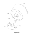
- FIGS. 7 a -7 f illustrate exemplary embodiments of an external unit.
- FIG. 8 is a top view of an implant unit, according to an exemplary embodiment of the present disclosure.
- FIG. 9 is a top view of another embodiment of an implant unit, according to an exemplary embodiment of the present disclosure.
- FIG. 10 illustrates circuitry of an implant unit and an external unit, according to an exemplary embodiment of the present disclosure.
- FIG. 11 illustrates a graph of quantities that may be used in determining energy delivery as a function coupling, according to an exemplary disclosed embodiment.
- Nerve modulation includes inhibition (e.g. blockage), stimulation, modification, regulation, or therapeutic alteration of activity, electrical or chemical, in the central, peripheral, or autonomic nervous system.
- Nerve modulation may take the form of nerve stimulation, which may include providing energy to the nerve to create a voltage change sufficient for the nerve to activate, or propagate an electrical signal of its own.
- Nerve modulation may also take the form of nerve inhibition, which may including providing energy to the nerve sufficient to prevent the nerve from propagating electrical signals. Nerve inhibition may be performed through the constant application of energy, and may also be performed through the application of enough energy to inhibit the function of the nerve for some time after the application.
- modulation of a nerve may include modulation of an entire nerve and/or modulation of a portion of a nerve.
- modulation of a motor neuron may be performed to affect only those portions of the neuron that are distal of the location to which energy is applied.
- a primary target response of nerve stimulation may include contraction of a tongue muscle (e.g., the muscle) in order to move the tongue to a position that does not block the patient's airway.
- nerve inhibition may be used to reduce or eliminate the sensation of pain.
- neural modulation may be used to increase, decrease, eliminate or otherwise modify nerve signals generated by the body to regulate blood pressure.
- embodiments of the present disclosure may be disclosed for use in patients with specific conditions, the embodiments may be used in conjunction with any patient/portion of a body where nerve modulation may be desired. That is, in addition to use in patients with sleep disordered breathing, migraine headaches, or hypertension, embodiments of the present disclosure may be use in many other areas, including, but not limited to: deep brain stimulation (e.g., treatment of epilepsy, Parkinson's, and depression); cardiac pace-making, stomach muscle stimulation (e.g., treatment of obesity), back pain, incontinence, menstrual pain, and/or any other condition that may be affected by neural modulation.
- deep brain stimulation e.g., treatment of epilepsy, Parkinson's, and depression
- cardiac pace-making e.g., treatment of obesity
- stomach muscle stimulation e.g., treatment of obesity
- back pain incontinence
- menstrual pain e.g., back pain, incontinence, menstrual pain, and/or any other condition that may be affected by neural modulation
- FIG. 1 illustrates an implant unit and external unit, according to an exemplary embodiment of the present disclosure.
- An implant unit 110 may be configured for implantation in a subject, in a location that permits it to modulate a nerve 115 .
- the implant unit 110 may be located in a subject such that intervening tissue 111 exists between the implant unit 110 and the nerve 115 .
- Intervening tissue may include muscle tissue, connective tissue, organ tissue, or any other type of biological tissue. Thus, location of implant unit 110 does not require contact with nerve 115 for effective neuromodulation.
- the implant unit 110 may also be located directly adjacent to nerve 115 , such that no intervening tissue 111 exists.
- implant unit 110 may be located on a genioglossus muscle of a patient. Such a location is suitable for modulation of the hypoglossal nerve, branches of which run inside the genioglossus muscle.
- implant 110 may be configured to modulate terminal fibers of the hypoglossal nerve from a location spaced apart from (e.g., not contacting) the terminal fibers.
- Implant unit 110 may also be configured for placement in other locations.
- migraine treatment may require subcutaneous implantation in the back of the neck, near the hairline of a subject, or behind the ear of a subject, to modulate the greater occipital nerve and/or the trigeminal nerve.
- Treating hypertension may require the implantation of a neuromodulation implant intravascularly inside the renal artery or renal vein (to modulate the parasympathetic renal nerves), either unilaterally or bilaterally, inside the carotid artery or jugular vein (to modulate the glossopharyngeal nerve through the carotid baroreceptors).
- a neuromodulation implant intravascularly inside the renal artery or renal vein (to modulate the parasympathetic renal nerves), either unilaterally or bilaterally, inside the carotid artery or jugular vein (to modulate the glossopharyngeal nerve through the carotid baroreceptors).
- treating hypertension may require the implantation of a neuromodulation implant subcutaneously, behind the ear or in the neck, for example, to directly modulate the glossopharyngeal nerve.
- External unit 120 may be configured for location external to a patient, either directly contacting, or close to the skin 112 of the patient. External unit 120 may be configured to be affixed to the patient, for example, by adhering to the skin 112 of the patient, or through a band or other device configured to hold external unit 120 in place. Adherence to the skin of external unit 120 may occur such that it is in the vicinity of the location of implant unit 110 .
- FIG. 2 illustrates an exemplary embodiment of a neuromodulation system for delivering energy in a patient 100 with sleep disordered breathing.
- the system may include an external unit 120 that may be configured for location external to the patient.
- external unit 120 may include devices for conveying power from a location external to a subject to a location within a subject.
- external unit 120 may include a carrier and an electronics housing, each configured as a portion of a system to convey power to implant unit 110 , located within the subject.
- external unit 120 may be configured to be affixed to the patient 100 .
- FIG. 2 illustrates that in a patient 100 with sleep disordered breathing, the external unit 120 may be configured for placement underneath the patient's chin and/or on the front of patient's neck.
- external unit 120 may be positioned at a location on the patient's skin opposite to a location of terminal fibers of the hypoglossal nerve. The suitability of placement locations may be determined by communication between external unit 120 and implant unit 110 , discussed in greater detail below.
- the external unit may be configured to be affixed anywhere suitable on a patient, such as the back of a patient's neck, i.e. for communication with a migraine treatment implant unit, on the outer portion of a patient's abdomen, i.e. for communication with a stomach modulating implant unit, on a patient's back, i.e. for communication with a renal artery modulating implant unit, and/or on any other suitable external location on a patient's skin, depending on the requirements of a particular application.
- a patient such as the back of a patient's neck, i.e. for communication with a migraine treatment implant unit, on the outer portion of a patient's abdomen, i.e. for communication with a stomach modulating implant unit, on a patient's back, i.e. for communication with a renal artery modulating implant unit, and/or on any other suitable external location on a patient's skin, depending on the requirements of a particular application.
- External unit 120 may further be configured to be affixed to an alternative location proximate to the patient.
- the external unit may be configured to fixedly or removably adhere to a strap or a band that may be configured to wrap around a part of a patient's body.
- the external unit may be configured to remain in a desired location external to the patient's body without adhering to that location.
- the external unit 120 may include a housing and a carrier.
- the housing may include any suitable container configured for retaining components.
- the housing may be any suitable size and/or shape and may be rigid or flexible.
- Non-limiting examples of housings for the external unit 120 include one or more of patches, buttons, or other receptacles having varying shapes and dimensions and constructed of any suitable material.
- the carrier may include any type of substrate, rigid or flexible, to which the housing may be mounted.
- the carrier may include a flexible material such that external unit 120 may be configured to conform to a desired location.
- the carrier may include a skin patch, which, in turn, may include a flexible substrate.
- the material of the flexible substrate may include, but is not limited to, plastic, silicone, woven natural fibers, and other suitable polymers, copolymers, and combinations thereof. Any portion of external unit 120 may be flexible or rigid, depending on the requirements of a particular application.
- external unit 120 may be configured to adhere to a desired location.
- at least one side of the carrier may include an adhesive material.
- the adhesive material may include a biocompatible material and may allow for a patient to adhere the external unit to the desired location and remove the external unit upon completion of use.
- the adhesive may be configured for single or multiple uses of the external unit. Suitable adhesive materials may include, but are not limited to biocompatible glues, starches, elastomers, thermoplastics, and emulsions.
- FIG. 3 schematically illustrates a system including external unit 120 and an implant unit 110 .
- internal unit 110 may be configured as a unit to be implanted into the body of a patient
- external unit 120 may be configured to send signals to and/or receive signals from implant unit 110 .
- various components may be included within a housing of external unit 120 or otherwise associated with external unit 120 .
- at least one processor 144 may be associated with external unit 120 .
- the at least one processor 144 may be located within the housing of external unit 120 .
- the at least one processor may be configured for wired or wireless communication with the external unit from a location external to the housing.
- the at least one processor may include any electric circuit that may be configured to perform a logic operation on at least one input variable.
- the at least one processor may therefore include one or more integrated circuits, microchips, microcontrollers, and microprocessors, which may be all or part of a central processing unit (CPU), a digital signal processor (DSP), a field programmable gate array (FPGA), or any other circuit known to those skilled in the art that may be suitable for executing instructions or performing logic operations.
- CPU central processing unit
- DSP digital signal processor
- FPGA field programmable gate array
- FIG. 3 illustrates that the external unit 120 may further be associated with a power source 140 .
- the power source may be removably couplable to the external unit at an exterior location relative to external unit.
- power source 140 may be permanently or removably coupled to a location within external unit 120 .
- the power source may further include any suitable source of power configured to be in electrical communication with the processor.
- the power source 140 may include a battery.
- the power source may be configured to power various components within the external unit. As illustrated in FIG. 3 , power source 140 may be configured to provide power to the processor 144 . In addition, the power source 140 may be configured to provide power to a signal source 142 .
- the signal source 142 may be in communication with the processor 144 and may include any device configured to generate a signal (e.g., a sinusoidal signal, square wave, triangle wave, microwave, radio-frequency (RF) signal, or any other type of electromagnetic signal).
- Signal source 142 may include, but is not limited to, a waveform generator that may be configured to generate alternating current (AC) signals and/or direct current (DC) signals. In one embodiment, for example, signal source 142 may be configured to generate an AC signal for transmission to one or more other components.
- Signal source 142 may be configured to generate a signal of any suitable frequency. In some embodiments, signal source 142 may be configured to generate a signal having a frequency of from about 6.5 MHz to about 13.6 MHz. In additional embodiments, signal source 142 may be configured to generate a signal having a frequency of from about 7.4 to about 8.8 MHz. In further embodiments, signal source 142 may generate a signal having a frequency as low as 90 kHz or as high as 28 MHz.
- Signal source 142 may be configured for direct or indirect electrical communication with an amplifier 146 .
- the amplifier may include any suitable device configured to amplify one or more signals generated from signal source 142 .
- Amplifier 146 may include one or more of various types of amplification devices, including, for example, transistor based devices, operational amplifiers, RF amplifiers, power amplifiers, or any other type of device that can increase the gain associated one or more aspects of a signal.
- the amplifier may further be configured to output the amplified signals to one or more components within external unit 120 .
- the external unit may additionally include a primary antenna 150 .
- the primary antenna may be configured as part of a circuit within external unit 120 and may be coupled either directly or indirectly to various components in external unit 120 .
- primary antenna 150 may be configured for communication with the amplifier 146 .
- the primary antenna may include any electrically conductive material that may be configured to create an electromagnetic field.
- the primary antenna may further be of any suitable size, shape, and/or configuration. The size, shape, and/or configuration may be determined by the size of the patient, the placement location of the implant unit, the size and/or shape of the implant unit, the amount of energy required to modulate a nerve, a location of a nerve to be modulated, the type of receiving electronics present on the implant unit, etc.
- the primary antenna may include any suitable antenna known to those skilled in the art that may be configured to send and/or receive signals. Suitable antennas may include, but are not limited to, a long-wire antenna, a patch antenna, a helical antenna, etc. In one embodiment, for example, as illustrated in FIG.
- primary antenna 150 may include a coil of electrically conductive material. Such a coil may be made from any suitable electrically conductive material and may be configured to include any suitable arrangement of conductive coils (e.g., diameter, number of coils, layout of coils, etc.).
- a coil antenna suitable for use as primary antenna 150 may have a diameter of between about 1 cm and 10 cm, and may be circular or oval shaped. In some embodiments, a coil antenna may have a diameter between 5 cm and 7 cm, and may be oval shaped.
- a coil antenna suitable for use as primary antenna 150 may have any number of windings, e.g. 4, 8, 12, or more.
- a coil antenna suitable for use as primary antenna 150 may have a wire diameter between about 0.01 mm and 2 mm.
- implant unit 110 may be configured to be implanted in a patient's body (e.g., beneath the patient's skin).
- FIG. 2 illustrates that the implant unit 110 may be configured to be implanted for modulation of a nerve associated with a muscle of the subject's tongue 130 .
- Modulating a nerve associated with a muscle of the subject's tongue 130 may include stimulation to cause a muscle contraction.
- the implant unit may be configured to be placed in conjunction with any nerve that one may desire to modulate. For example, modulation of the occipital nerve, the greater occipital nerve, and/or the trigeminal nerve may be useful for treating pain sensation in the head, such as that from migraines.
- Modulation of parasympathetic nerve fibers on and around the renal arteries may be useful for treating hypertension.
- any nerve of the peripheral nervous system both spinal and cranial
- motor neurons, sensory neurons, sympathetic neurons and parasympathetic neurons may be modulated to achieve a desired effect.
- Implant unit 110 may be formed of any materials suitable for implantation into the body of a patient.
- implant unit 110 may include a flexible carrier 161 ( FIG. 8 ) including a flexible, biocompatible material.
- Such materials may include, for example, silicone, polyimides, phenyltrimethoxysilane (PTMS), polymethyl methacrylate (PMMA), Parylene C, polyimide, liquid polyimide, laminated polyimide, black epoxy, polyether ether ketone (PEEK), Liquid Crystal Polymer (LCP), Kapton, etc.
- Implant unit 110 may further include circuitry including conductive materials, such as gold, platinum, titanium, or any other biocompatible conductive material or combination of materials.
- Implant unit 110 and flexible carrier 161 may also be fabricated with a thickness suitable for implantation under a patient's skin. Implant 110 may have thickness of less than about 4 mm or less than about 2 mm.
- implant unit 110 may include a secondary antenna 152 mounted onto or integrated with flexible carrier 161 .
- the secondary antenna may include any suitable antenna known to those skilled in the art that may be configured to send and/or receive signals.
- the secondary antenna may include any suitable size, shape, and/or configuration. The size, shape and/or configuration may be determined by the size of the patient, the placement location of the implant unit, the amount of energy required to modulate the nerve, etc.
- Suitable antennas may include, but are not limited to, a long-wire antenna, a patch antenna, a helical antenna, etc.
- secondary antenna 152 may include a coil antenna having a circular shape (see also FIG. 8 ) or oval shape.
- a coil antenna may be made from any suitable conductive material and may be configured to include any suitable arrangement of conductive coils (e.g., diameter, number of coils, layout of coils, etc.).
- a coil antenna suitable for use as secondary antenna 152 may have a diameter of between about 5 mm and 30 mm, and may be circular or oval shaped.
- a coil antenna suitable for use as secondary antenna 152 may have any number of windings, e.g. 4, 15, 20, 30, or 50.
- a coil antenna suitable for use as secondary antenna 152 may have a wire diameter between about 0.001 mm and 1 mm.
- FIGS. 4 a and 4 b illustrate a double-layer crossover antenna 1101 suitable for use as a primary antenna 150 . While the double-layer crossover antenna 1101 illustrated in FIGS. 4 a and 4 b includes features making it suitable for use as a primary antenna 150 , some or all of the features of the double-layer crossover antenna, as described below, may also be utilized in a secondary antenna 152 . While a double-layer crossover antenna is shown and described, other antenna configurations may also be suitable for primary antenna 150 and/or secondary antenna 152 . For example, single layer antennas may be used where antenna components (e.g., coils) are arranged in a single layer, e.g., either on or within a dielectric or insulating material.
- antenna components e.g., coils
- a crossover pattern is shown, other patterns may also be suitable.
- a wire associated with primary antenna 150 and/or secondary antenna 152 may include a pattern of traces of progressively decreasing dimension.
- each loop could include rings of progressively decreasing diameter to create a pattern that spirals inwardly.
- a similar approach may be viable using traces of other shapes as well.
- FIG. 4 a this figure illustrates a single coil of double-layer crossover antenna 1101
- FIG. 4 b illustrates two layers of double layer crossover antenna 1101
- Antenna 1101 may include a first coil of wire 1102 arranged on a first side of a dielectric carrier 1104 and a second coil of wire 1103 on a second side of a dielectric carrier 1104 .
- Arranging the antenna coils in a double layer may serve to increase the transmission range of the antenna without increasing the size of the antenna. Such an arrangement, however, may also serve to increase capacitance between the wires of each coil.
- an amount of parasitic capacitance between wires may partially depend on the distance each wire is from its neighbor.
- capacitance may be generated between each loop of the coil and its neighbors to either side. Thus, more compact coils may generate more parasitic capacitance.
- additional capacitance may then be generated between the wires of the first coil and the wires of the second coil.
- This additional capacitance may be further increased if corresponding loops of the first and second coils have the same or similar diameters, and/or if a dielectric carrier separating the loops is made very thin.
- Increased parasitic capacitance in an antenna may serve to alter characteristics, such as resonant frequency, of the antenna in unpredictable amounts based on manufacturing specifications. Additionally, resonant frequency drift, caused, for example by moisture incursion or antenna flexing, may be increased by the presence of increased parasitic capacitance. Thus, in order to decrease variability in the manufactured product, it may be advantageous to reduce the levels of parasitic capacitance in a dual layer antenna.
- FIG. 4 b illustrates a double layer crossover antenna 1101 which may exhibit a parasitic capacitance in a manufactured antenna lower than single layer counterparts.
- a first coil of wire 1102 is concentrically offset from a second coil of wire 1103 .
- concentrically offsetting corresponding loops of each wire coil serves to increase the distance between a single loop of the first coil 1102 with a corresponding loop of the second coil 1103 . This increased distance, in turn, may decrease the parasitic wire-to-wire capacitance between loops of first coil 1102 and corresponding loops of second coil 1103 .
- This configuration may be particularly advantageous in reducing parasitic capacitance in a situation where a dielectric carrier 1104 is thin enough such that the concentric distance by which each coil is offset is relatively large compared to the thickness of the dielectric carrier 1104 .
- a concentric offset of 0.5 mm or more may produce a large change in parasitic capacitance.
- a concentric offset of 0.5 mm may produce a smaller change in parasitic capacitance.
- the concentric offset between a first coil 1102 and a second coil 1103 may be achieved, for example, by a plurality of electrical trace steps 1105 that offset each loop of the coils from each preceding loop. Electrical trace steps 1105 on a first side of dielectric carrier 1104 cross over electrical trace steps 1105 on a second side of dielectric carrier 1104 , thus providing the crossover feature of double-layer crossover antenna 1101 .
- double layer crossover antenna 1101 may include openings 1106 in dielectric carrier 1104 to facilitate the electrical connection of first and second coils 1102 , 1103 .
- First and second coils 1102 , 1103 of double layer crossover antenna 1101 may also include exposed electrical portions 1108 , 1109 configured to electrically connect with an electrical connector of a device housing that may be coupled to antenna 1101 .
- Exposed electrical portions 1108 , 1109 may be configured so as to maintain electrical contact with the electrical connector of a device housing independent of the axial orientation of the connection. As shown in FIG. 4 a , for example, exposed electrical portions 1108 , 1109 may be configured as continuous or discontinuous circles in order to achieve this.
- a first exposed electrical portion 1108 configured as a discontinuous circle may provide a space through which an electrical trace may pass without contacting the first exposed electrical portion, for example to connect with a second exposed electrical portion 1109 located inside the first, or to other components located within the circle of the first exposed electrical portion 1108 .
- FIG. 4 a illustrates an antenna having substantially elliptical coils; other shapes, such as circular, triangular, square, etc., may be also be used in different embodiments.
- Elliptical coils may facilitate placement of external unit 120 in certain areas (e.g., under the chin of a subject) while maintaining desirable electrical performance characteristics.
- FIGS. 5 a and 5 b illustrate an exemplary embodiment of external unit 120 , including features that may be found in any combination in other embodiments.
- FIG. 5 a illustrates a side view of external unit 120 , depicting carrier 1201 and electronics housing 1202 .
- Housing 1202 may be configured to contain various electrical and mechanical components, as further discussed below with respect to FIG. 5 a .
- Housing 1202 may include a bottom surface 1250 , a top surface 1252 , and at least one sidewall 1251 .
- sidewall 1251 may include a continuous surface.
- Bottom surface 1250 may be configured to directly contact carrier 1201 or various contacts may be included on bottom surface 1250 to interact with carrier 1201 .
- Carrier 1201 may include a skin patch configured for adherence to the skin of a subject, for example through adhesives of mechanical means.
- Carrier 1201 may be flexible or rigid, or may have flexible portions and rigid portions.
- carrier 1201 may constitute a flexible adhesive patch.
- Carrier 1201 may be associated with a coil of electrically conductive material, for example, primary antenna 150 .
- primary antenna 150 may be located on or within carrier 1201 .
- carrier 1201 may include a double-layer crossover antenna 1101 such as the antennas illustrated in FIGS. 4 a and 4 b . As illustrated in FIG.
- carrier 1201 may also include a power source 140 , which may include a battery 1290 , such as a paper battery, thin film battery, or other type of substantially flat and/or flexible battery. Carrier 1201 may also include any other type of battery or power source.
- a power source 140 which may include a battery 1290 , such as a paper battery, thin film battery, or other type of substantially flat and/or flexible battery.
- Carrier 1201 may also include any other type of battery or power source.
- Carrier 1201 may also include a connector 1203 configured for selectively or removably connecting carrier 1201 to electronics housing 1202 .
- connector 1203 may constitute a mechanical connector that includes at least one portion that extends away from carrier 1201 .
- connector 1203 may include a protrusion extending or protruding from carrier 1201 .
- Connector 1203 may be configured to be received and retained by a receiver 1204 of electronics housing 1202 . Retention of connector 1203 by receiver 1204 may be selective such that connector 1203 may be selectively removable from receiver 1204 .
- Connector 1203 may include various configurations.
- connector 1203 may include a rodlike element 1231 .
- Rodlike element 1231 may include any elongated structure of any cross-section.
- rodlike element 1231 may be circular or oval in cross section, or may include a square or other-sided polygonal cross-section.
- Rodlike element 1231 may include a single integral protrusion, or may consist of several discrete protrusions grouped together to form rodlike element 1231 . Such discrete portions may include flexible arms 1234 .
- Connector 1203 may further include a detent portion 1232 , for example, a notch or tab configured to engage with a corresponding detent engagement portion 1233 disposed on receiver 1204 .
- Detent engagement portion may be, for example, a lip, rim, or flange.
- detent portion 1232 may be disposed on flexible arms 1234 , configured to elastically bend to permit engagement with receiver 1204 and return to their original positions to retain electronics housing 1202 in a mounted configuration.
- connector 1203 may include a bayonet connector.
- connector 1203 may include a twist-lock connector.
- connector 1203 may include various combinations of the above described retention features.
- connector 1203 may be configured to provide a selective connection to electronics housing 1204 without the substantial use of a concave feature into which at least a portion of housing 1202 is introduced in order to retain housing 1202 with carrier 1201 .
- Connector 1203 may include, for example a peg, and may have flexible arms.
- Connector 1203 may further include a magnetic connection, a velcro connection, and/or a snap dome connection.
- Connector 1203 may also include a locating feature, configured to locate electronics housing 1202 at a specific height, axial location, and/or axial orientation with respect to carrier 1201 .
- a locating feature of connector 1203 may further include pegs, rings, boxes, ellipses, bumps, etc.
- Connector 1203 may be centered on carrier 1201 , may be offset from the center by a predetermined amount, or may be provided at any other suitable location of carrier 1201 . Multiple connectors 1203 may be provided on carrier 1201 . Connector 1203 may be configured such that removal from electronics housing 1202 causes breakage of connector 1203 . Such a feature may be desirable to prevent re-use of carrier 1201 , which may lose some efficacy through continued use.
- Receiver 1204 may also include various configurations to facilitate the retention of mechanical connector 1203 .
- receiver 1204 may include an opening into which mechanical connector 1203 extends.
- the opening may be a concavity 1235 , configured to receive and retain connector 1203 .
- the concavity may include a rim portion, extending around at least a portion of the perimeter of the interior of the cavity, and configured to engage a detent portion 1232 of connector 1203 .
- Alternative embodiments or receiver 1204 and connector 1203 are described below with respect to FIGS. 7 a - f.
- housing 1202 when a user mounts housing 1202 to carrier 1201 , housing 1202 may be retained by connector 1203 in a manner in which at least a portion of a sidewall 1251 and a top surface 1252 of the housing is exposed when mounted to the carrier.
- the exposure of a portion of a sidewall 1251 and a top surface 1252 of the housing may permit a user to easily grasp housing 1202 , to facilitate mounting and/or removal from carrier 1201 .
- connector 1203 may engage with receiver 1204 at portions of the perimeter, thereby leaving at least top surface 1252 exposed.
- Electronics housing 1202 is illustrated in side view in FIG. 5 a and in a bottom view in FIG. 5 b .
- Electronics housing 1202 may include electronics portion 1205 , which may be arranged inside electronics housing 1202 in any manner that is suitable.
- Electronics portion 1205 may include various components, further discussed below, of external unit 120 .
- electronics portion 1205 may include any combination of at least one processor 144 associated with external unit 120 , a power source 140 , such as a battery, a primary antenna 152 , and an electrical circuit 170 .
- Electronics portion 1205 may also include any other component described herein as associated with external unit 120 . Additional components may also be recognized by those of skill in the art.
- Electronics housing 1202 may include receiver 1204 configured to receive and retain connector 1203 .
- Electronics housing 1202 may include at least one electrical connector 1210 , 1211 , 1212 .
- Electrical connectors 1210 , 1211 , 1212 may be arranged with pairs of electrical contacts, as shown in FIG. 5 b , or with any other number of electrical contacts.
- the pair of electrical contacts of each electrical connector 1210 , 1211 , 1212 may be electrically connected with each other inside of housing 1202 , such that the pair of electrical contacts represents a single connection point to a circuit.
- electrical connectors 1210 , 1211 , and 1212 may thus include redundant electrical contacts.
- the electrical contacts of each electrical connector 1210 , 1211 , 1212 may also represent opposite ends of a circuit, for example, the positive and negative ends of a battery charging circuit. In an exemplary embodiment, as shown in FIG.
- mechanical connector 1203 may be configured to maintain contact between electrical connectors 1210 , 1211 , and 1212 , arranged on bottom surface 1250 of housing 1202 and exposed electrical portions 1108 , 1109 (FIG. 6 ) of carrier 1201 when mechanical connector 1203 is received by receiver 1204 of electronics housing 1202 .
- mechanical connector 1203 may be adapted to permit relative rotation between carrier 1201 and housing 1202 .
- housing 1202 may include a spin on connector 1203 , permitting relative rotation between carrier 1201 and housing 1202 .
- mechanical connector 1203 engages with receiver 1204 disposed on a perimeter of housing 1202 housing 1202 may be permitted to rotate within a circular portion defined by mechanical connector 1203 .
- electrical connectors 1210 , 1211 , and 1212 may be configured so as to maintain electrical contact with an exposed electrical portions 1108 , 1109 independent of an axial orientation of electronics housing 1202 . Connection between any or all of electrical connectors 1210 , 1211 , 1212 and exposed electrical portions 1108 , 1109 may thus be established and maintained irrespective of relative axial positions of carrier 1201 and housing 1202 . Thus, when connector 1203 is received by receiver 1204 , housing 1202 may rotate with respect to carrier 1201 without interrupting electrical contact between at least one of electrical connectors 1210 , 1211 , 1212 and exposed electrical portions 1108 , 1109 .
- Axial orientation independence may be achieved, for example, through the use of circular exposed electrical portions 1108 , 1109 and each of a pair of contact portions 1213 of electrical connectors 1210 , 1211 , 1212 disposed equidistant from a center of receiver 1204 at a radius approximately equal to that of a corresponding exposed first electrical portion 1108 .
- at least one electrical contact 1213 of electrical connectors 1210 , 1211 , and 1212 may make contact with a corresponding first electrical portion 1108 .
- electrical connectors 1210 , 1211 , 1212 are illustrated as pairs of rectangular electrical contacts. Electrical connectors 1210 , 1211 , 1212 , however, may include any number of contacts 1213 , be configured as continuous or discontinuous circles, or have any other suitable shape or configuration.
- electronics housing 1202 may include more electrical connectors 1210 , 1211 , 1212 , than a carrier 1201 includes exposed electrical portions 1108 .
- electronics housing 1202 includes three electrical connectors 1210 , 1211 , and 1212 , while a double-layer crossover antenna 1101 includes two exposed electrical portions 1108 .
- each of connectors 1210 , 1211 , and 1212 includes two electrical contact portions 1213 .
- connectors 1210 , 1211 , and 1212 may include fewer or more than two electrical contact portions.
- the multiple electrical contact portions 1213 of an individual electrical connector 1210 , 1211 , or 1212 are in continuous electrical communication with each other, such that there is minimal electrical resistance between the multiple contact portions 1213 or each individual connector.
- two of electrical connectors 1210 , 1211 , and 1212 may each be configured with two electrical contact portions 1213 .
- Electrical connectors 1211 and 1212 may be arranged such that connector 1211 , through its contact portions 1213 , makes contact with first exposed electrical portion 1108 and connector 1210 , through its contact portions 1213 , makes contact with second exposed electrical portion 1109 .
- Exposed electrical portions 1108 and 1109 represent opposite ends of double layer crossover antenna 1101 .
- antenna 1101 may be electrically connected to the electrical components contained in electronics portion 1205 .
- contact portions 1213 of electrical connector 1210 may be configured so as not to contact either of exposed electrical portions 1108 , 1109 .
- electrical connector 1210 may be reserved to function as opposite ends of a battery charging circuit, in order to charge a battery contained in electronics portion 1205 when electronics housing 1202 is not being used for therapy.
- a battery charger unit may be provided with a connector similar to that of connector 1203 , and configured to engage with receiver 1204 . Upon engaging with receiver 1204 , electrode contacts of the battery charger unit may contact electrical contact portions 1213 of connector 1210 to charge a battery contained within electronics portion 1205 .
- an activator chip may include electronics housing 1202 .
- Processor 144 may be configured to activate when at least one of electrical connectors 1210 , 1211 , 1212 contact exposed electrical portions 1108 , 1109 included in carrier 1201 .
- an electronics housing 1202 may be charged and left dormant for an extended period of time (e.g., one or more days) prior to activation. Simply connecting electronics housing 1202 to carrier 1201 (and inducing contact between an electrical connector 1210 , 1211 , 1212 and an electrical portion 1108 , 1109 ) may cause the processor to activate.
- processor 144 may be configured to enter a specific mode of operation, such as a calibration mode (for calibrating the processor after placement of the carrier on the skin), a placement mode (for assisting a user to properly place the carrier on the skin), and/or a therapy mode (to begin a therapy session).
- the various modes of processor 144 may include waiting periods at the beginning, end, or at any time during.
- a placement mode may include a waiting period at the end of the mode to provide a period during which a subject may fall asleep.
- a therapy mode may include a similar waiting period at the beginning of the mode.
- processor 144 may be configured to provide waiting periods separate from the described modes, in order to provide a desired temporal spacing between system activities.
- FIG. 6 provides a perspective view of an exemplary external unit 120 .
- carrier 1201 may include a connector 1203 extending from carrier 1201 .
- Connector 1203 may be configured to be received and retained by a receiver associated with housing 1202 .
- connector 1203 may be configured as a peg, post, tab (or any of the structures described above relative to connector 1203 ) shaped to be received into one or more recessed areas associated with housing 1202 .
- connector 1203 and/or housing 1202 may include structures (e.g., detents, etc.) to enable selective attachment to and retention of connector 1203 by housing 1202 .
- housing 1202 may be mounted on carrier 1201 . Once mounted, the electrical connectors 1210 , 1211 , 1212 of housing 1202 may engage with exposed electrical portions 1108 , 1109 of carrier 1201 .
- FIGS. 7 a - f illustrate several additional exemplary embodiments of structures for enabling selective mounting of housing 1202 to carrier 1201 .
- FIG. 7 a illustrates an exemplary embodiment of an external unit featuring a bayonet mount.
- connector 1203 may include extending portions 1218 configured to extend or protrude from carrier 1201 . Extending portions 1218 may include receptor slots 1238 and retaining portions 1241 . Further, connector 1203 may include at least one biasing mechanism 1240 configured to extend or protrude from the carrier.
- Receiver 1203 may include a plurality of radial pins 1239 , corresponding in number to receptor slots 1238 . Radial pins 1239 may be disposed on a portion of a perimeter of the housing.
- Carrier 1201 is not illustrated in FIG. 7 a ; however, connector 1203 may form part of carrier 1201 , for example, as an integrally formed portion or as a portion affixed to carrier 1201 .
- Radial pins 1239 may be configured as protrusions extending from the housing, and may be configured to engage and retain receptor slots 1238 of connector 1203 . Radial pins 1239 may further be configured to be inserted into the receptor slots 1238 and to securely engage connector 1203 when the housing 1202 is rotated with respect to connector 1203 .
- FIG. 7 a illustrates an embodiment including two radial pins 1239 , any suitable number of radial pins 1239 may be included.
- Biasing mechanism 1240 may provide a vertical force to seat radial pins 1239 in retention portion 1241 of receptor slot 1238 .
- Biasing mechanism 1240 may include any type of elastically deformable element capable of providing a biasing force.
- biasing mechanism may include a spring, or may include flexible plastic tabs.
- biasing mechanism 1240 and electrical connectors 1210 , 1211 , and 1212 may be incorporated in the same structure.
- electrical connectors 1210 , 1211 , and 1212 may include elastically deformable metal tabs configured to act as biasing mechanism 1240 by providing a biasing force.
- Biasing mechanism 1240 may be provided on as part of connector 1203 (as illustrated) or, in some embodiments, as part of receiver 1204 on housing 1202 .
- FIG. 7 b illustrates an additional embodiment including a bayonet mount.
- FIG. 7 b illustrates a bayonet mount including three radial pins 1239 .
- Carrier 1201 is not illustrated in FIG. 7 b ; however, connector 1203 may form part of carrier 1201 , for example, as an integrally formed portion or as a portion affixed to carrier 1201 .
- FIG. 7 c illustrate an additional embodiment including a bayonet mount.
- carrier 1201 is not illustrated in FIG. 7 c .
- Connector 1203 may include an extending portion 1218 and biasing mechanisms 1240 configured to extend or protrude from carrier 1201 .
- protruding connector 1203 may include radial pins 1239 for bayonet mounting, and may be arranged inside of a perimeter provided by biasing mechanism 1240 .
- Receiver 1204 may include a recessed portion including receptor slot 1238 and retention portions 1241 .
- Connector 1203 may be configured to engage and be retained by receiver 1204 by inserting extending portion 1218 into the recessed portion of receiver 1204 and rotating housing 1202 with respect to connector 1203 .
- biasing mechanisms 1240 may be compressed.
- biasing mechanisms 1240 may press housing 1202 away from carrier 1201 , thus preventing further rotation between the two.
- FIG. 7 d illustrates an embodiment wherein receiver 1204 includes an annular groove 1217 and is disposed on at least a portion of a perimeter of housing 1202 .
- annular groove 1217 may form a recessed portion of receiver 1204 .
- Annular groove 1217 may include a detent engagement portion 1233 , for example, a lip, rim, or flange.
- receiver 1204 may be configured to engage a connector 1203 including a plurality of flexible extension arms 1236 .
- Flexible arms 1236 may each include a detent portion 1232 , such as a tab or a hook, for engagement with detent engagement portion 1233 of annular groove 1217 .
- flexible extension arms 1236 may elastically deform outwards to accommodate receiver 1204 before “snapping” into an engaged position.
- carrier 1201 is not illustrated in FIG. 7 d , Flexible extension arms 1236 of connector 1203 may extend or protrude from carrier 1201 .
- FIG. 7 e illustrates an embodiment wherein mechanical connector 1203 features both a central rodlike element 1231 and flexible extension arms 1236 arranged at a perimeter. Both connector 1203 and flexible extension arms 1236 may extend or protrude from carrier 1201 (not illustrated). Rodlike element 1231 may also include flexible extension arms 1234 . Either or both of flexible extension arms 1236 and 1234 may include detent portions 1232 . Receiver 1204 , in this embodiment, may include a plurality of recessed portions, for example, both a centrally located concavity 1235 and a peripherally located annular groove 1217 of housing 1202 .
- Either or both of annular groove 1217 and concavity 1235 may include detent engagement portions 1233 to engage detent portions 1232 of extension arms 1236 and/or extension arms 1234 , respectively.
- retention of housing 1202 may be secured by either or both of the engagement between rodlike element 1231 and concavity 1235 and the engagement between extension arms 1236 and annular groove 1217 .
- Extension arms 1234 and 1236 may be configured to elastically deform to facilitate engagement.
- either rodlike element 1231 or flexible arms 1236 do not include detent portions, and function only facilitate alignment of connector 1203 and receiver 1204 .
- FIG. 7 f shows an embodiment configured to engage connector 1203 including a twist-lock connector.
- receiver 1204 may include a plurality of recesses 1237 including detent engagement portions 1233 while connector 1203 includes a plurality of extension arms 1236 including detent portions 1232 .
- the extension arms 1236 may be configured to be inserted into the recesses 1237 and to securely engage the housing 1202 when the housing 1202 is rotated with respect to the extension arms 1236 .
- Extension arms 1236 of connector 1203 may extend or protrude from carrier 1201 (not illustrated).
- receiver 1204 and connector 1203 are provided for exemplary purposes only.
- the exemplary embodiments discuss various combinations of features that provide a releasable engagement between carrier 1201 and housing 1202 .
- the various features described may be combined in different ways.
- the embodiments discussed in the foregoing generally include a receiver 1204 disposed on a housing 1202 and a connector 1203 disposed on a carrier 1201 , this arrangement may be reversed. That is, receiver 1204 may be located on carrier 1201 and connector 1203 may be located on housing 1202 .
- connector 1203 and receiver 1204 may include any or all of the features discussed above with respect to connector 1203 and receiver 1204 .
- connector 1203 may be a protrusion extending from housing 1202 , and receiver 1204 may include recessed portion or concavity of carrier 1201 .
- connector 1203 may be configured to engage and be retained within the recessed portion or concavity of receiver 1204 .
- at least a portion of a sidewall 1251 and a top surface 1252 of housing 1202 may be exposed when the housing is mounted on the flexible adhesive patch.
- Implant unit 110 may additionally include a plurality of field-generating implant electrodes 158 a , 158 b .
- the electrodes may include any suitable shape and/or orientation on the implant unit so long as the electrodes may be configured to generate an electric field in the body of a patient.
- Implant electrodes 158 a and 158 b may also include any suitable conductive material (e.g., copper, silver, gold, platinum, iridium, platinum-iridium, platinum-gold, conductive polymers, etc.) or combinations of conductive (and/or noble metals) materials.
- the electrodes may include short line electrodes, circular electrodes, and/or circular pairs of electrodes. As shown in FIG.
- electrodes 158 a and 158 b may be located on an end of a first extension 162 a of an elongate arm 162 .
- the electrodes may be located on any portion of implant unit 110 .
- implant unit 110 may include electrodes located at a plurality of locations, for example on an end of both a first extension 162 a and a second extension 162 b of elongate arm 162 , as illustrated, for example, in FIG. 9 .
- Implant electrodes may have a thickness between about 200 nanometers and 1 millimeter.
- Anode and cathode electrode pairs may be spaced apart by about a distance of about 0.2 mm to 25 mm.
- anode and cathode electrode pairs may be spaced apart by a distance of about 1 mm to 10 mm, or between 4 mm and 7 mm.
- Adjacent anodes or adjacent cathodes may be spaced apart by distances as small as 0.001 mm or less, or as great as 25 mm or more. In some embodiments, adjacent anodes or adjacent cathodes may be spaced apart by a distance between about 0.2 mm and 1 mm.
- FIG. 8 provides a representation of an exemplary configuration of implant unit 110 .
- the field-generating electrodes 158 a and 158 b may include two sets of four circular electrodes, provided on flexible carrier 161 , with one set of electrodes providing an anode and the other set of electrodes providing a cathode.
- Implant unit 110 may include one or more structural elements to facilitate implantation of implant unit 110 into the body of a patient. Such elements may include, for example, elongated arms, suture holes, polymeric surgical mesh, biological glue, spikes of flexible carrier protruding to anchor to the tissue, spikes of additional biocompatible material for the same purpose, etc.
- implant unit 110 may include an elongate arm 162 having a first extension 162 a and, optionally, a second extension 162 b . Extensions 162 a and 162 b may aid in orienting implant unit 110 with respect to a particular muscle (e.g., the genioglossus muscle), a nerve within a patient's body, or a surface within a body above a nerve.
- a particular muscle e.g., the genioglossus muscle
- first and second extensions 162 a , 162 b may be configured to enable the implant unit to conform at least partially around soft or hard tissue (e.g., nerve, bone, or muscle, etc.) beneath a patient's skin.
- implant unit 110 may also include one or more suture holes 160 located anywhere on flexible carrier 161 .
- suture holes 160 may be placed on second extension 162 b of elongate arm 162 and/or on first extension 162 a of elongate arm 162 .
- Implant unit 110 may be constructed in various shapes. Additionally, or alternatively, implant unit 110 may include surgical mesh 1050 or other perforatable material. In some embodiments, implant unit may appear substantially as illustrated in FIG. 8 .
- implant unit 110 may lack illustrated structures such as second extension 162 b , or may have additional or different structures in different orientations. Additionally, implant unit 110 may be formed with a generally triangular, circular, or rectangular shape, as an alternative to the winged shape shown in FIG. 8 . In some embodiments, the shape of implant unit 110 (e.g., as shown in FIG. 8 ) may facilitate orientation of implant unit 110 with respect to a particular nerve to be modulated. Thus, other regular or irregular shapes may be adopted in order to facilitate implantation in differing parts of the body.
- implant unit 110 may include a protective coating that encapsulates implant unit 110 .
- the protective coating may be made from a flexible material to enable bending along with flexible carrier 161 .
- the encapsulation material of the protective coating may also resist humidity penetration and protect against corrosion.
- the protective coating may include a plurality of layers, including different materials or combinations of materials in different layers
- FIG. 9 is a view of an alternate embodiment of an implant unit 110 , according to an exemplary embodiment of the present disclosure.
- implant unit 110 may include a plurality of electrodes, located, for example, at the ends of first extension 162 a and second extension 162 b .
- FIG. 9 illustrates an embodiment wherein implant electrodes 158 a and 158 b include line electrodes.
- external unit 120 may be configured to communicate with implant unit 110 .
- a primary signal may be generated on primary antenna 150 , using, e.g., processor 144 , signal source 142 , and amplifier 146 .
- power source 140 may be configured to provide power to one or both of the processor 144 and the signal source 142 .
- the processor 144 may be configured to cause signal source 142 to generate a signal (e.g., an RF energy signal).
- Signal source 142 may be configured to output the generated signal to amplifier 146 , which may amplify the signal generated by signal source 142 .
- the amount of amplification and, therefore, the amplitude of the signal may be controlled, for example, by processor 144 .
- the amount of gain or amplification that processor 144 causes amplifier 146 to apply to the signal may depend on a variety of factors, including, but not limited to, the shape, size, and/or configuration of primary antenna 150 , the size of the patient, the location of implant unit 110 in the patient, the shape, size, and/or configuration of secondary antenna 152 , a degree of coupling between primary antenna 150 and secondary antenna 152 (discussed further below), a desired magnitude of electric field to be generated by implant electrodes 158 a , 158 b , etc.
- Amplifier 146 may output the amplified signal to primary antenna 150 .
- External unit 120 may communicate a primary signal on primary antenna to the secondary antenna 152 of implant unit 110 . This communication may result from coupling between primary antenna 150 and secondary antenna 152 .
- Such coupling of the primary antenna and the secondary antenna may include any interaction between the primary antenna and the secondary antenna that causes a signal on the secondary antenna in response to a signal applied to the primary antenna.
- coupling between the primary and secondary antennas may include capacitive coupling, inductive coupling, radiofrequency coupling, etc. and any combinations thereof.
- Coupling between primary antenna 150 and secondary antenna 152 may depend on the proximity of the primary antenna relative to the secondary antenna. That is, in some embodiments, an efficiency or degree of coupling between primary antenna 150 and secondary antenna 152 may depend on the proximity of the primary antenna to the secondary antenna.
- the proximity of the primary and secondary antennas may be expressed in terms of a coaxial offset (e.g., a distance between the primary and secondary antennas when central axes of the primary and secondary antennas are co-aligned), a lateral offset (e.g., a distance between a central axis of the primary antenna and a central axis of the secondary antenna), and/or an angular offset (e.g., an angular difference between the central axes of the primary and secondary antennas).
- a coaxial offset e.g., a distance between the primary and secondary antennas when central axes of the primary and secondary antennas are co-aligned
- a lateral offset e.g., a distance between a central
- a theoretical maximum efficiency of coupling may exist between primary antenna 150 and secondary antenna 152 when both the coaxial offset, the lateral offset, and the angular offset are zero. Increasing any of the coaxial offset, the lateral offset, and the angular offset may have the effect of reducing the efficiency or degree of coupling between primary antenna 150 and secondary antenna 152 .
- a secondary signal may arise on secondary antenna 152 when the primary signal is present on the primary antenna 150 .
- Such coupling may include inductive/magnetic coupling, RF coupling/transmission, capacitive coupling, or any other mechanism where a secondary signal may be generated on secondary antenna 152 in response to a primary signal generated on primary antenna 150 .
- Coupling may refer to any interaction between the primary and secondary antennas.
- circuit components associated with implant unit 110 may also affect the secondary signal on secondary antenna 152 .
- the secondary signal on secondary antenna 152 may refer to any and all signals and signal components present on secondary antenna 152 regardless of the source.
- a signal on primary antenna 150 induced by a secondary signal on secondary antenna 152 may be referred to as a primary coupled signal component.
- the primary signal may refer to any and all signals or signal components present on primary antenna 150 , regardless of source, and the primary coupled signal component may refer to any signal or signal component arising on the primary antenna as a result of coupling with signals present on secondary antenna 152 .
- the primary coupled signal component may contribute to the primary signal on primary antenna 150 .
- Implant unit 110 may be configured to respond to external unit 120 .
- a primary signal generated on primary coil 150 may cause a secondary signal on secondary antenna 152 , which in turn, may cause one or more responses by implant unit 110 .
- the response of implant unit 110 may include the generation of an electric field between implant electrodes 158 a and 158 b.
- FIG. 10 illustrates circuitry 170 that may be included in external unit 120 and circuitry 180 that may be included in implant unit 110 . Additional, different, or fewer circuit components may be included in either or both of circuitry 170 and circuitry 180 .
- secondary antenna 152 may be arranged in electrical communication with implant electrodes 158 a , 158 b .
- circuitry connecting secondary antenna 152 with implant electrodes 158 a and 158 b may cause a voltage potential across implant electrodes 158 a and 158 b in the presence of a secondary signal on secondary antenna 152 .
- This voltage potential may be referred to as a field inducing signal, as this voltage potential may generate an electric field between implant electrodes 158 a and 158 b .
- the field inducing signal may include any signal (e.g., voltage potential) applied to electrodes associated with the implant unit that may result in an electric field being generated between the electrodes.
- the field inducing signal may be generated as a result of conditioning of the secondary signal by circuitry 180 .
- circuitry 170 of external unit 120 may be configured to generate an AC primary signal on primary antenna 150 that may cause an AC secondary signal on secondary antenna 152 .
- it may be advantageous e.g., in order to generate a unidirectional electric field for modulation of a nerve to provide a DC field inducing signal at implant electrodes 158 a and 158 b .
- circuitry 180 in implant unit 110 may include an AC-DC converter.
- the AC to DC converter may include any suitable converter known to those skilled in the art.
- the AC-DC converter may include rectification circuit components including, for example, diode 156 and appropriate capacitors and resistors.
- implant unit 110 may include an AC-AC converter, or no converter, in order to provide an AC field inducing signal at implant electrodes 158 a and 158 b.
- the field inducing signal may be configured to generate an electric field between implant electrodes 158 a and 158 b .
- the magnitude and/or duration of the generated electric field resulting from the field inducing signal may be sufficient to modulate one or more nerves in the vicinity of electrodes 158 a and 158 b .
- the field inducing signal may be referred to as a modulation signal.
- the magnitude and/or duration of the field inducing signal may generate an electric field that does not result in nerve modulation. In such cases, the field inducing signal may be referred to as a sub-modulation signal.
- a modulation signal may include a moderate amplitude and moderate duration, while in other embodiments, a modulation signal may include a higher amplitude and a shorter duration.
- Various amplitudes and/or durations of field-inducing signals across electrodes 158 a , 158 b may result in modulation signals, and whether a field-inducing signal rises to the level of a modulation signal can depend on many factors (e.g., distance from a particular nerve to be stimulated; whether the nerve is branched; orientation of the induced electric field with respect to the nerve; type of tissue present between the electrodes and the nerve; etc.).
- a field inducing signal constitutes a modulation signal (resulting in an electric field that may cause nerve modulation) or a sub-modulation signal (resulting in an electric field not intended to cause nerve modulation) may ultimately be controlled by processor 144 of external unit 120 .
- processor 144 may determine that nerve modulation is appropriate. Under these conditions, processor 144 may cause signal source 144 and amplifier 146 to generate a modulation control signal on primary antenna 150 (i.e., a signal having a magnitude and/or duration selected such that a resulting secondary signal on secondary antenna 152 will provide a modulation signal at implant electrodes 158 a and 158 b ).
- Processor 144 may be configured to limit an amount of energy transferred from external unit 120 to implant unit 110 .
- implant unit 110 may be associated with a threshold energy limit that may take into account multiple factors associated with the patient and/or the implant. For example, in some cases, certain nerves of a patient should receive no more than a predetermined maximum amount of energy to minimize the risk of damaging the nerves and/or surrounding tissue.
- circuitry 180 of implant unit 110 may include components having a maximum operating voltage or power level that may contribute to a practical threshold energy limit of implant unit 110 . Processor 144 may be configured to account for such limitations when setting the magnitude and/or duration of a primary signal to be applied to primary antenna 150 .
- processor 144 may also determine a lower power threshold based, at least in part, on an efficacy of the delivered power.
- the lower power threshold may be computed based on a minimum amount of power that enables nerve modulation (e.g., signals having power levels above the lower power threshold may constitute modulation signals while signals having power levels below the lower power threshold may constitute sub-modulation signals).
- a lower power threshold may also be measured or provided in alternative ways.
- appropriate circuitry or sensors in the implant unit 110 may measure a lower power threshold.
- a lower power threshold may be computed or sensed by an additional external device, and subsequently programmed into processor 144 , or programmed into implant unit 110 .
- implant unit 110 may be constructed with circuitry 180 specifically chosen to generate signals at the electrodes of at least the lower power threshold.
- an antenna of external unit 120 may be adjusted to accommodate or produce a signal corresponding to a specific lower power threshold.
- the lower power threshold may vary from patient to patient, and may take into account multiple factors, such as, for example, modulation characteristics of a particular patient's nerve fibers, a distance between implant unit 110 and external unit 120 after implantation, and the size and configuration of implant unit components (e.g., antenna and implant electrodes), etc.
- Processor 144 may also be configured to cause application of sub-modulation control signals to primary antenna 150 .
- Such sub-modulation control signals may include an amplitude and/or duration that result in a sub-modulation signal at electrodes 158 a , 158 b . While such sub-modulation control signals may not result in nerve modulation, such sub-modulation control signals may enable feedback-based control of the nerve modulation system. That is, in some embodiments, processor 144 may be configured to cause application of a sub-modulation control signal to primary antenna 150 . This signal may induce a secondary signal on secondary antenna 152 , which, in turn, induces a primary coupled signal component on primary antenna 150 .
- external unit 120 may include a feedback circuit 148 (e.g., a signal analyzer or detector, etc.), which may be placed in direct or indirect communication with primary antenna 150 and processor 144 .
- Sub-modulation control signals may be applied to primary antenna 150 at any desired periodicity. In some embodiments, the sub-modulation control signals may be applied to primary antenna 150 at a rate of one every five seconds (or longer). In other embodiments, the sub-modulation control signals may be applied more frequently (e.g., once every two seconds, once per second, once per millisecond, once per nanosecond, or multiple times per second). Further, it should be noted that feedback may also be received upon application of modulation control signals to primary antenna 150 (i.e., those that result in nerve modulation), as such modulation control signals may also result in generation of a primary coupled signal component on primary antenna 150 .
- the primary coupled signal component may be fed to processor 144 by feedback circuit 148 and may be used as a basis for determining a degree of coupling between primary antenna 150 and secondary antenna 152 .
- the degree of coupling may enable determination of the efficacy of the energy transfer between two antennas.
- Processor 144 may also use the determined degree of coupling in regulating delivery of power to implant unit 110 .
- Processor 144 may be configured with any suitable logic for determining how to regulate power transfer to implant unit 110 based on the determined degree of coupling. For example, where the primary coupled signal component indicates that a degree of coupling has changed from a baseline coupling level, processor 144 may determine that secondary antenna 152 has moved with respect to primary antenna 150 (either in coaxial offset, lateral offset, or angular offset, or any combination). Such movement, for example, may be associated with a movement of the implant unit 110 , and the tissue that it is associated with based on its implant location. Thus, in such situations, processor 144 may determine that modulation of a nerve in the patient's body is appropriate.
- processor 144 may cause application of a modulation control signal to primary antenna 150 in order to generate a modulation signal at implant electrodes 158 a , 158 b , e.g., to cause modulation of a nerve of the patient.
- movement of an implant unit 110 may be associated with movement of the tongue, which may indicate the onset of a sleep apnea event or a sleep apnea precursor.
- the onset of a sleep apnea event of sleep apnea precursor may require the stimulation of the genioglossus muscle of the patient to relieve or avert the event. Such stimulation may result in contraction of the muscle and movement of the patient's tongue away from the patient's airway.
- processor 144 may be configured to generate a modulation control signal based on a signal from a user, for example, or a detected level of neural activity in a sensory neuron (e.g. the greater occipital nerve or trigeminal nerve) associated with head pain.
- a modulation control signal generated by the processor and applied to the primary antenna 150 may generate a modulation signal at implant electrodes 158 a , 158 b , e.g., to cause inhibition or blocking of a sensory nerve of the patient. Such inhibition or blocking may decrease or eliminate the sensation of pain for the patient.
- processor 144 may be configured to generate a modulation control signal based on, for example, pre-programmed instructions and/or signals from an implant indicative of blood pressure.
- a modulation control signal generated by the processor and applied to the primary antenna 150 may generate a modulation signal at implant electrodes 158 a , 158 b , e.g., to cause either inhibition or stimulation of nerve of a patient, depending on the requirements.
- a neuromodulator placed in a carotid artery or jugular artery i.e.
- a modulation control signal tailored to induce a stimulation signal at the electrodes may receive a modulation control signal tailored to induce a stimulation signal at the electrodes, thereby causing the glossopharyngeal nerve associated with the carotid baroreceptors to fire at an increased rate in order to signal the brain to lower blood pressure.
- Similar modulation of the glossopharyngeal nerve may be achieved with a neuromodulator implanted in a subcutaneous location in a patient's neck or behind a patient's ear.
- a neuromodulator place in a renal artery may receive a modulation control signal tailored to cause an inhibiting or blocking signal at the electrodes, thereby inhibiting a signal to raise blood pressure carried from the renal nerves to the kidneys.
- Modulation control signals may include stimulation control signals, and sub-modulation control signals may include sub-stimulation control signals.
- Stimulation control signals may have any amplitude, pulse duration, or frequency combination that results in a stimulation signal at electrodes 158 a , 158 b .
- stimulation control signals may include a pulse duration of greater than about 50 microseconds and/or an amplitude of approximately 0.5 amps, or between 0.1 amps and 1 amp, or between 0.05 amps and 3 amps.
- Sub-stimulation control signals may have a pulse duration less than about 500, or less than about 200 nanoseconds and/or an amplitude less than about 1 amp, 0.5 amps, 0.1 amps, 0.05 amps, or 0.01 amps.
- pulse duration less than about 500, or less than about 200 nanoseconds and/or an amplitude less than about 1 amp, 0.5 amps, 0.1 amps, 0.05 amps, or 0.01 amps.
- these values are meant to provide a general reference only, as various combinations of values higher than or lower than the exemplary guidelines provided may or may not result in nerve stimulation.
- stimulation control signals may include a pulse train, wherein each pulse includes a plurality of sub-pulses.
- An alternating current signal (e.g., at a frequency of between about 6.5-13.6 MHz) may be used to generate the pulse train, as follows.
- a sub-pulse may have a duration of between 50-250 microseconds, or a duration of between 1 microsecond and 2 milliseconds, during which an alternating current signal is turned on. For example, a 200 microsecond sub-pulse of a 10 MHz alternating current signal will include approximately 2000 periods.
- Each pulse may, in turn, have a duration of between 100 and 500 milliseconds, during which sub-pulses occur at a frequency of between 25 and 100 Hz.
- a 200 millisecond pulse of 50 Hz sub-pulses will include approximately 10 sub-pulses.
- each pulse may be separated from the next by a duration of between 0.2 and 2 seconds.
- a pulse train of 200 millisecond pulses each separated by 1.3 seconds from the next, a new pulse will occur every 1.5 seconds.
- a pulse train of this embodiment may be utilized, for example, to provide ongoing stimulation during a treatment session.
- a treatment session may be a period of time during which a subject is asleep and in need of treatment to prevent sleep disordered breathing. Such a treatment session may last anywhere from about three to ten hours.
- a treatment session may be of varying length according to the duration of the treated condition.
- Processor 144 may be configured to determine a degree of coupling between primary antenna 150 and secondary antenna 152 by monitoring one or more aspects of the primary coupled signal component received through feedback circuit 148 . In some embodiments, processor 144 may determine a degree of coupling between primary antenna 150 and secondary antenna 152 by monitoring a voltage level associated with the primary coupled signal component, a current level, or any other attribute that may depend on the degree of coupling between primary antenna 150 and secondary antenna 152 . For example, in response to periodic sub-modulation signals applied to primary antenna 150 , processor 144 may determine a baseline voltage level or current level associated with the primary coupled signal component.
- This baseline voltage level may be associated with a range of movement of the patient's tongue when a sleep apnea event or its precursor is not occurring, e.g. during normal breathing.
- the coaxial, lateral, or angular offset between primary antenna 150 and secondary antenna 152 may change.
- the degree of coupling between primary antenna 150 and secondary antenna 152 may change, and the voltage level or current level of the primary coupled signal component on primary antenna 150 may also change.
- Processor 144 may be configured to recognize a sleep apnea event or its precursor when a voltage level, current level, or other electrical characteristic associated with the primary coupled signal component changes by a predetermined amount or reaches a predetermined absolute value.
- FIG. 11 provides a graph that illustrates this principle in more detail.
- graph 200 plots a rate of change in induced current in the receiving coil as a function of coaxial distance between the coils.
- graph 200 illustrates the sensitivity of the induced current to further displacement between the coils, moving them either closer together or further apart. It also indicates that, overall, the induced current in the secondary coil will decrease as the secondary coil is moved away from the primary, drive coil, i.e. the rate of change of induced current, in mA/mm, is consistently negative.
- the sensitivity of the induced current to further displacement between the coils varies with distance.
- the rate of change in current as a function of additional displacement in a 14 mm coil is approximately ⁇ 6 mA/mm. If the displacement of the coils is approximately 22 mm, the rate of change in the induced current in response to additional displacement is approximately ⁇ 11 mA/mm, which corresponds to a local maximum in the rate of change of the induced current. Increasing the separation distance beyond 22 mm continues to result in a decline in the induced current in the secondary coil, but the rate of change decreases. For example, at a separation distance of about 30 mm, the 14 mm coil experiences a rate of change in the induced current in response to additional displacement of about ⁇ 8 mA/mm.
- processor 144 may be able to determine a particular degree of coupling between primary antenna 150 and secondary antenna 152 , at any given time, by observing the magnitude and/or rate of change in the magnitude of the current associated with the primary coupled signal component on primary antenna 150 .
- an initially detected coupling degree may establish a baseline range when the patient attaches external unit 120 to the skin. Presumably, while the patient is awake, the tongue is not blocking the patient's airway and moves with the patients breathing in a natural range, where coupling between primary antenna 150 and secondary antenna 152 may be within a baseline range.
- a baseline coupling range may encompass a maximum coupling between primary antenna 150 and secondary antenna 152 .
- a baseline coupling range may also encompass a range that does not include a maximum coupling level between primary antenna 150 and secondary antenna 152 .
- the initially determined coupling may be fairly representative of a non-sleep apnea condition and may be used by processor 144 as a baseline in determining a degree of coupling between primary antenna 150 and secondary antenna 152 .
- processor 144 may periodically scan over a range of primary signal amplitudes to determine current values related to coupling. If a periodic scan results in determination of a degree of coupling different from the baseline coupling, processor 144 may determine that there has been a change from the baseline initial conditions.
- processor 144 may be configured to determine, in situ, appropriate parameter values for the modulation control signal that will ultimately result in nerve modulation. For example, by determining the degree of coupling between primary antenna 150 and secondary antenna 152 , processor 144 may be configured to select characteristics of the modulation control signal (e.g., amplitude, pulse duration, frequency, etc.) that may provide a modulation signal at electrodes 158 a , 158 b in proportion to or otherwise related to the determined degree of coupling. In some embodiments, processor 144 may access a lookup table or other data stored in a memory correlating modulation control signal parameter values with degree of coupling. In this way, processor 144 may adjust the applied modulation control signal in response to an observed degree of coupling.
- characteristics of the modulation control signal e.g., amplitude, pulse duration, frequency, etc.
- processor 144 may access a lookup table or other data stored in a memory correlating modulation control signal parameter values with degree of coupling. In this way, processor 144 may adjust the applied modul
- processor 144 may be configured to determine the degree of coupling between primary antenna 150 and secondary antenna 152 during modulation.
- the tongue, or other structure on or near which the implant is located, and thus implant unit 110 may move as a result of modulation.
- the degree of coupling may change during modulation.
- Processor 144 may be configured to determine the degree of coupling as it changes during modulation, in order to dynamically adjust characteristics of the modulation control signal according to the changing degree of coupling. This adjustment may permit processor 144 to cause implant unit 110 to provide an appropriate modulation signal at electrodes 158 a , 158 b throughout a modulation event.
- processor 144 may alter the primary signal in accordance with the changing degree of coupling in order to maintain a constant modulation signal, or to cause the modulation signal to be reduced in a controlled manner according to patient needs.
- the response of processor 144 may be correlated to the determined degree of coupling.
- processor 144 may determine that only a small response is necessary.
- processor 144 may select modulation control signal parameters that will result in a relatively small response (e.g., a short stimulation of a nerve, small muscle contraction, etc.).
- processor 144 may determine that a larger response is required. As a result, processor 144 may select modulation control signal parameters that will result in a larger response. In some embodiments, only enough power may be transmitted to implant unit 110 to cause the desired level of response. In other words, processor 144 may be configured to cause a metered response based on the determined degree of coupling between primary antenna 150 and secondary antenna 152 . As the determined degree of coupling decreases, processor 144 may cause transfer of power in increasing amounts.
- the predetermined coupling threshold e.g., where the tongue has moved enough to cause a sleep apnea event
- Such an approach may preserve battery life in the external unit 120 , may protect circuitry 170 and circuitry 180 , may increase effectiveness in addressing the type of detected condition (e.g., sleep apnea, snoring, tongue movement, etc.), and may be more comfortable for the patient.
- type of detected condition e.g., sleep apnea, snoring, tongue movement, etc.
- processor 144 may employ an iterative process in order to select modulation control signal parameters that result in a desired response level. For example, upon determining that a modulation control signal should be generated, processor 144 may cause generation of an initial modulation control signal based on a set of predetermined parameter values. If feedback from feedback circuit 148 indicates that a nerve has been modulated (e.g, if an increase in a degree of coupling is observed), then processor 144 may return to a monitoring mode by issuing sub-modulation control signals.
- processor 144 may change one or more parameter values associated with the modulation control signal (e.g., the amplitude, pulse duration, etc.).
- processor 144 may increase one or more parameters of the modulation control signal periodically until the feedback indicates that nerve modulation has occurred. Where nerve modulation occurred, but did not produce the desired result, processor 144 may re-evaluate the degree of coupling between primary antenna 150 and secondary antenna 152 and select new parameters for the modulation control signal targeted toward achieving a desired result. For example, where stimulation of a nerve causes the tongue to move only partially away from the patient's airway, additional stimulation may be desired. Because the tongue has moved away from the airway, however, implant unit 110 may be closer to external unit 120 and, therefore, the degree of coupling may have increased.
- processor 144 can select new parameters for the stimulation control signal aimed at moving the tongue the remaining distance to the desired location.
- processor 144 may be configured to sweep over a range of parameter values until nerve modulation is achieved. For example, in circumstances where an applied sub-modulation control signal results in feedback indicating that nerve modulation is appropriate, processor 144 may use the last applied sub-modulation control signal as a starting point for generation of the modulation control signal.
- the amplitude and/or pulse duration (or other parameters) associated with the signal applied to primary antenna 150 may be iteratively increased by predetermined amounts and at a predetermined rate until the feedback indicates that nerve modulation has occurred.
- Processor 144 may be configured to determine or derive various physiologic data based on the determined degree of coupling between primary antenna 150 and secondary antenna 152 .
- the degree of coupling may indicate a distance between external unit 120 and implant unit 110 , which processor 144 may use to determine a position of external unit 120 or a relative position of a patient's tongue.
- Monitoring the degree of coupling can also provide such physiologic data as whether a patient's tongue is moving or vibrating (e.g, whether the patient is snoring), by how much the tongue is moving or vibrating, the direction of motion of the tongue, the rate of motion of the tongue, etc.
- processor 144 may regulate delivery of power to implant unit 110 based on the determined physiologic data. For example, processor 144 may select parameters for a particular modulation control signal or series of modulation control signals for addressing a specific condition relating to the determined physiologic data. If the physiologic data indicates that the tongue is vibrating, for example, processor 144 may determine that a sleep apnea event is likely to occur and may issue a response by delivering power to implant unit 110 in an amount selected to address the particular situation.
- processor 144 may opt to not deliver power and wait to determine if the tongue clears on its own. Alternatively, processor 144 may deliver a small amount of power to implant unit 110 (e.g., especially where a determined rate of movement indicates that the tongue is moving slowly away from the patient's airway) to encourage the tongue to continue moving away from the patient's airway or to speed its progression away from the airway.
- processor 144 may be configured with software and/or logic enabling it to address a variety of different physiologic scenarios with particularity. In each case, processor 144 may be configured to use the physiologic data to determine an amount of power to be delivered to implant unit 110 in order to modulate nerves associated with the tongue with the appropriate amount of energy.
- the disclosed embodiments may be used in conjunction with a method for regulating delivery of power to an implant unit.
- the method may include determining a degree of coupling between primary antenna 150 associated with external unit 120 and secondary antenna 152 associated with implant unit 110 , implanted in the body of a patient. Determining the degree of coupling may be accomplished by processor 144 located external to implant unit 110 and that may be associated with external unit 120 . Processor 144 may be configured to regulate delivery of power from the external unit to the implant unit based on the determined degree of coupling.
- the degree of coupling determination may enable the processor to further determine a location of the implant unit.
- the motion of the implant unit may correspond to motion of the body part where the implant unit may be attached. This may be considered physiologic data received by the processor.
- the processor may, accordingly, be configured to regulate delivery of power from the power source to the implant unit based on the physiologic data.
- the degree of coupling determination may enable the processor to determine information pertaining to a condition of the implant unit. Such a condition may include location as well as information pertaining to an internal state of the implant unit.
- the processor may, according to the condition of the implant unit, be configured to regulate delivery of power from the power source to the implant unit based on the condition data.
- implant unit 110 may include a processor located on the implant.
- a processor located on implant unit 110 may perform all or some of the processes described with respect to the at least one processor associated with an external unit.
- a processor associated with implant unit 110 may be configured to receive a control signal prompting the implant controller to turn on and cause a modulation signal to be applied to the implant electrodes for modulating a nerve.
- Such a processor may also be configured to monitor various sensors associated with the implant unit and to transmit this information back to and external unit.
- Power for the processor unit may be supplied by an onboard power source or received via transmissions from an external unit.
- implant unit 110 may be self-sufficient, including its own power source and a processor configured to operate the implant unit 110 with no external interaction.
- the processor of implant unit 110 could be configured to monitor conditions in the body of a subject (via one or more sensors or other means), determining when those conditions warrant modulation of a nerve, and generate a signal to the electrodes to modulate a nerve.
- the power source could be regenerative based on movement or biological function; or the power sources could be periodically rechargeable from an external location, such as, for example, through induction.
Landscapes
- Health & Medical Sciences (AREA)
- Engineering & Computer Science (AREA)
- Animal Behavior & Ethology (AREA)
- Veterinary Medicine (AREA)
- Biomedical Technology (AREA)
- Nuclear Medicine, Radiotherapy & Molecular Imaging (AREA)
- Radiology & Medical Imaging (AREA)
- Life Sciences & Earth Sciences (AREA)
- Public Health (AREA)
- General Health & Medical Sciences (AREA)
- Computer Networks & Wireless Communication (AREA)
- Physics & Mathematics (AREA)
- Signal Processing (AREA)
- Physiology (AREA)
- Pulmonology (AREA)
- Electromagnetism (AREA)
- Acoustics & Sound (AREA)
- Power Engineering (AREA)
- Electrotherapy Devices (AREA)
Abstract
Description
Claims (10)
Priority Applications (3)
| Application Number | Priority Date | Filing Date | Title |
|---|---|---|---|
| US13/951,754 US9907967B2 (en) | 2012-07-26 | 2013-07-26 | Transcutaneous power conveyance device |
| US14/059,632 US9855032B2 (en) | 2012-07-26 | 2013-10-22 | Transcutaneous power conveyance device |
| US15/897,107 US10814137B2 (en) | 2012-07-26 | 2018-02-14 | Transcutaneous power conveyance device |
Applications Claiming Priority (2)
| Application Number | Priority Date | Filing Date | Title |
|---|---|---|---|
| US201261676327P | 2012-07-26 | 2012-07-26 | |
| US13/951,754 US9907967B2 (en) | 2012-07-26 | 2013-07-26 | Transcutaneous power conveyance device |
Related Child Applications (2)
| Application Number | Title | Priority Date | Filing Date |
|---|---|---|---|
| US14/059,632 Continuation US9855032B2 (en) | 2012-07-26 | 2013-10-22 | Transcutaneous power conveyance device |
| US15/897,107 Continuation US10814137B2 (en) | 2012-07-26 | 2018-02-14 | Transcutaneous power conveyance device |
Publications (3)
| Publication Number | Publication Date |
|---|---|
| US20150032177A1 US20150032177A1 (en) | 2015-01-29 |
| US20180021586A9 US20180021586A9 (en) | 2018-01-25 |
| US9907967B2 true US9907967B2 (en) | 2018-03-06 |
Family
ID=52391120
Family Applications (2)
| Application Number | Title | Priority Date | Filing Date |
|---|---|---|---|
| US13/951,754 Active US9907967B2 (en) | 2012-07-26 | 2013-07-26 | Transcutaneous power conveyance device |
| US15/897,107 Active 2033-10-24 US10814137B2 (en) | 2012-07-26 | 2018-02-14 | Transcutaneous power conveyance device |
Family Applications After (1)
| Application Number | Title | Priority Date | Filing Date |
|---|---|---|---|
| US15/897,107 Active 2033-10-24 US10814137B2 (en) | 2012-07-26 | 2018-02-14 | Transcutaneous power conveyance device |
Country Status (1)
| Country | Link |
|---|---|
| US (2) | US9907967B2 (en) |
Cited By (5)
| Publication number | Priority date | Publication date | Assignee | Title |
|---|---|---|---|---|
| US11213685B2 (en) | 2017-06-13 | 2022-01-04 | Bluewind Medical Ltd. | Antenna configuration |
| US11559683B2 (en) | 2018-06-01 | 2023-01-24 | Zennea Technologies Inc. | Method and device for treating sleep related breathing disorders |
| US11883668B2 (en) | 2020-11-04 | 2024-01-30 | Invicta Medical, Inc. | Implantable electrodes with remote power delivery for treating sleep apnea, and associated systems and methods |
| US11964154B1 (en) | 2022-12-22 | 2024-04-23 | Invicta Medical, Inc. | Signal delivery devices to treat sleep apnea, and associated methods and systems |
| US12246175B2 (en) | 2023-03-17 | 2025-03-11 | Invicta Medical, Inc. | Methods for positioning signal delivery devices to treat sleep apnea, and associated devices and treatments |
Families Citing this family (12)
| Publication number | Priority date | Publication date | Assignee | Title |
|---|---|---|---|---|
| CN103457319B (en) * | 2013-08-21 | 2015-09-02 | 宁波天瑞电器有限公司 | Onboard charger |
| ES2702906T3 (en) | 2013-11-19 | 2019-03-06 | Cleveland Clinic Found | System for treating obstructive sleep apnea using a neuromuscular stimulator |
| US10608468B2 (en) * | 2016-06-28 | 2020-03-31 | Apple Inc. | Wireless charging systems with in-band communications |
| US9941937B1 (en) * | 2017-04-10 | 2018-04-10 | Nxp B.V. | Near-field electromagnetic induction (NFEMI) antenna |
| EP3716494A1 (en) * | 2019-03-26 | 2020-09-30 | Koninklijke Philips N.V. | Connector providing a connection through a flexible barrier |
| KR102900262B1 (en) | 2019-03-28 | 2025-12-16 | 선라이즈 에스에이 | A system comprising a device and a detection unit for processing data related to disturbances that may occur during the subject's sleep. |
| US12257069B2 (en) | 2019-03-28 | 2025-03-25 | Sunrise Sa | System comprising a sensing unit and a device for processing data relating to disturbances that may occur during the sleep of a subject |
| EP4241690A3 (en) | 2019-05-02 | 2023-10-25 | XII Medical, Inc. | Systems for improving sleep disordered breathing |
| WO2021076188A1 (en) | 2019-10-15 | 2021-04-22 | Enhale Medical, Inc. | Biased neuromodulation lead and method of using same |
| US11666751B2 (en) * | 2020-01-24 | 2023-06-06 | Medtronic Xomed, Inc. | Combination obstructive sleep apnea trialing lead and chronic lead |
| AU2021354921B2 (en) | 2020-10-01 | 2023-06-15 | Sunrise Sa | Wearable device for decreasing the respiratory effort of a sleeping subject |
| US11691010B2 (en) | 2021-01-13 | 2023-07-04 | Xii Medical, Inc. | Systems and methods for improving sleep disordered breathing |
Citations (34)
| Publication number | Priority date | Publication date | Assignee | Title |
|---|---|---|---|---|
| US4495917A (en) | 1982-03-26 | 1985-01-29 | The Regents Of The University Of California | Surgically implantable disconnect device |
| US5948006A (en) * | 1998-10-14 | 1999-09-07 | Advanced Bionics Corporation | Transcutaneous transmission patch |
| USRE36626E (en) | 1990-09-10 | 2000-03-28 | The Aps Organization, Llp | Iontophoretic drug delivery apparatus |
| US20020188333A1 (en) * | 1999-12-23 | 2002-12-12 | Matthew Nowick | External battery power source for implanted medical devices |
| US6530876B1 (en) | 2000-04-25 | 2003-03-11 | Paul A. Spence | Supplemental heart pump methods and systems for supplementing blood through the heart |
| US20030050549A1 (en) | 2001-09-13 | 2003-03-13 | Jerzy Sochor | Implantable lead connector assembly for implantable devices and methods of using it |
| US20030139782A1 (en) | 2002-01-21 | 2003-07-24 | Michael Duncan | FES stimulator |
| WO2004058322A2 (en) | 2002-12-16 | 2004-07-15 | Meagan Medical, Inc. | Coupling percutaneous devices to a patient |
| US20050060030A1 (en) | 2000-01-31 | 2005-03-17 | Lashinski Randall T. | Remotely activated mitral annuloplasty system and methods |
| US20050283203A1 (en) | 2003-12-29 | 2005-12-22 | Flaherty J C | Transcutaneous implant |
| US20060264835A1 (en) | 2003-10-21 | 2006-11-23 | Novo Nordisk A/S | Medical skin mountable device |
| US20070106167A1 (en) * | 2001-07-26 | 2007-05-10 | Datascope Investment Corp. | Patient-worn medical monitoring device |
| US20070179584A1 (en) * | 2002-03-28 | 2007-08-02 | Northstar Neuroscience, Inc. | Electrode geometries for efficient neural stimulation |
| US20080004676A1 (en) * | 2006-06-16 | 2008-01-03 | Osypka Thomas P | Implantable neurostimulation systems |
| US20080082147A1 (en) | 2006-09-29 | 2008-04-03 | Rongqing Dai | External Coil Assembly for Implantable Medical Prostheses |
| US20080109046A1 (en) * | 2006-02-16 | 2008-05-08 | Lima Marcelo G | RFID-based apparatus, system, and method for therapeutic treatment of obstructive sleep apnea |
| US20080161874A1 (en) | 2004-02-12 | 2008-07-03 | Ndi Medical, Inc. | Systems and methods for a trial stage and/or long-term treatment of disorders of the body using neurostimulation |
| US7555345B2 (en) | 2005-03-11 | 2009-06-30 | Medtronic, Inc. | Implantable neurostimulator device |
| US20090182394A1 (en) | 2008-01-07 | 2009-07-16 | Thomas Jerome Bachinski | Systems and methods for therapeutic electrical stimulation |
| US20090233491A1 (en) | 2008-03-12 | 2009-09-17 | Boston Scientific Neuromodulation Corporation | Low-profile connector for a neurostimulation lead |
| US20100036445A1 (en) | 2008-08-01 | 2010-02-11 | Ndi Medical Llc. | Portable assemblies, systems, and methods for providing functional or therapeutic neurostimulation |
| US20100049028A1 (en) * | 2005-10-20 | 2010-02-25 | Samsung Electronics Co., Ltd. | Electrode for living body and device for detecting living signal |
| US20100268305A1 (en) | 2005-04-29 | 2010-10-21 | Medtronic, Inc. | Alignment indication for transcutaneous energy transfer |
| US20100298842A1 (en) | 2006-04-21 | 2010-11-25 | Daglow Terry D | Burr hole cap and methods of use |
| US20100312188A1 (en) | 2008-12-15 | 2010-12-09 | Timothy Robertson | Body-Associated Receiver and Method |
| US20110082515A1 (en) | 2006-10-11 | 2011-04-07 | Imad Libbus | Transcutaneous neurostimulator for treating hypertension |
| US7962211B2 (en) | 2006-04-28 | 2011-06-14 | Medtronic, Inc. | Antenna for an external power source for an implantable medical device, system and method |
| US20110218408A1 (en) | 2010-03-02 | 2011-09-08 | Medtronic, Inc. | Medical system with identification patch |
| US20110257495A1 (en) | 2009-02-26 | 2011-10-20 | Abbott Diabetes Care Inc. | Analyte Monitoring Device and Methods |
| US20110257701A1 (en) * | 2004-02-12 | 2011-10-20 | Ndi Medical, Llc | Portable assemblies, systems and methods for providing functional or therapeutic neurostimulation |
| US20120139485A1 (en) | 2003-10-02 | 2012-06-07 | Medtronic, Inc. | External power source for an implantable medical device having an adjustable carrier frequency and system and method related therefore |
| US20120203318A1 (en) | 2009-10-13 | 2012-08-09 | Mann Alfred E | Neural stimulator with percutaneous connectivity |
| US8267708B1 (en) | 2007-08-09 | 2012-09-18 | Jerzy Roman Sochor | Implantable feedthrough-based connector |
| US20120330126A1 (en) * | 2009-12-23 | 2012-12-27 | Delta, Dansk Elektronik, Lys Og Akustik | Monitoring device for attachment to a surface of a subject |
Family Cites Families (309)
| Publication number | Priority date | Publication date | Assignee | Title |
|---|---|---|---|---|
| US3606881A (en) | 1970-02-20 | 1971-09-21 | Riley D Woodson | Conductive rubber electrode |
| US4905011A (en) | 1987-07-20 | 1990-02-27 | E-Systems, Inc. | Concentric ring antenna |
| JPH067724Y2 (en) | 1988-08-05 | 1994-03-02 | 日本精線株式会社 | Living wire |
| US5307818A (en) | 1989-02-15 | 1994-05-03 | Jacob Segalowitz | Wireless electrocardiographic and monitoring system and wireless electrode assemblies for same |
| GB9011036D0 (en) * | 1990-05-16 | 1990-07-04 | Veeder Root Ltd | Bayonet connector |
| US5549655A (en) | 1994-09-21 | 1996-08-27 | Medtronic, Inc. | Method and apparatus for synchronized treatment of obstructive sleep apnea |
| US5540732A (en) | 1994-09-21 | 1996-07-30 | Medtronic, Inc. | Method and apparatus for impedance detecting and treating obstructive airway disorders |
| US5546952A (en) | 1994-09-21 | 1996-08-20 | Medtronic, Inc. | Method and apparatus for detection of a respiratory waveform |
| US5540733A (en) | 1994-09-21 | 1996-07-30 | Medtronic, Inc. | Method and apparatus for detecting and treating obstructive sleep apnea |
| US5591216A (en) | 1995-05-19 | 1997-01-07 | Medtronic, Inc. | Method for treatment of sleep apnea by electrical stimulation |
| US5702431A (en) | 1995-06-07 | 1997-12-30 | Sulzer Intermedics Inc. | Enhanced transcutaneous recharging system for battery powered implantable medical device |
| US5690693A (en) | 1995-06-07 | 1997-11-25 | Sulzer Intermedics Inc. | Transcutaneous energy transmission circuit for implantable medical device |
| US6198970B1 (en) | 1995-10-27 | 2001-03-06 | Esd Limited Liability Company | Method and apparatus for treating oropharyngeal respiratory and oral motor neuromuscular disorders with electrical stimulation |
| US7039468B2 (en) | 1995-10-27 | 2006-05-02 | Esd Limited Liability Company | Method and apparatus for treating oropharyngeal disorders with electrical stimulation |
| US5725564A (en) | 1995-10-27 | 1998-03-10 | Esd Limited Liability Company | Method and apparatus for treating dysphagia with electrical stimulation |
| US7280873B2 (en) | 1995-10-27 | 2007-10-09 | Esd, Llc | Treatment of oropharyngeal disorders by application of neuromuscular electrical stimulation |
| US5891185A (en) | 1995-10-27 | 1999-04-06 | Esd Limited Liability Company | Method and apparatus for treating oropharyngeal disorders with electrical stimulation |
| WO1997029802A2 (en) | 1996-02-20 | 1997-08-21 | Advanced Bionics Corporation | Improved implantable microstimulator and systems employing the same |
| FR2796562B1 (en) | 1996-04-04 | 2005-06-24 | Medtronic Inc | TECHNIQUES FOR STIMULATING LIVING TISSUE AND RECORDING WITH LOCAL CONTROL OF ACTIVE SITES |
| WO1997037720A1 (en) | 1996-04-04 | 1997-10-16 | Medtronic, Inc. | Living tissue stimulation and recording techniques |
| DE69722782T2 (en) | 1996-04-04 | 2004-02-12 | Medtronic, Inc., Minneapolis | DEVICE FOR STIMULATING LIVING TISSUE AND RELEVANT RECORDING |
| JP2002512000A (en) | 1996-06-04 | 2002-04-16 | メド―エル・エレクトロメディツィニシェ・ゲラーテ・ゲーエムベーハー | A device that transmits electromagnetic energy between a primary coil and a secondary coil |
| US6132384A (en) | 1996-06-26 | 2000-10-17 | Medtronic, Inc. | Sensor, method of sensor implant and system for treatment of respiratory disorders |
| US5741316A (en) | 1996-12-02 | 1998-04-21 | Light Sciences Limited Partnership | Electromagnetic coil configurations for power transmission through tissue |
| US5873898A (en) | 1997-04-29 | 1999-02-23 | Medtronic, Inc. | Microprocessor capture detection circuit and method |
| WO1999020339A1 (en) | 1997-10-17 | 1999-04-29 | Respironics, Inc. | Muscle stimulating device and method for diagnosing and treating a breathing disorder |
| JPH11195921A (en) | 1997-12-26 | 1999-07-21 | Kokusai Electric Co Ltd | Card antenna |
| US6009878A (en) | 1998-02-02 | 2000-01-04 | Medtronic, Inc. | System for locating implantable medical device |
| US6305381B1 (en) | 1998-02-02 | 2001-10-23 | Medtronic Inc. | System for locating implantable medical device |
| US5945762A (en) | 1998-02-10 | 1999-08-31 | Light Sciences Limited Partnership | Movable magnet transmitter for inducing electrical current in an implanted coil |
| US20030030342A1 (en) | 1998-02-10 | 2003-02-13 | Chen James C. | Contactless energy transfer apparatus |
| US6331744B1 (en) | 1998-02-10 | 2001-12-18 | Light Sciences Corporation | Contactless energy transfer apparatus |
| US6281611B1 (en) | 1998-02-10 | 2001-08-28 | Light Sciences Corporation | Use of moving element to produce heat |
| US6058330A (en) | 1998-03-06 | 2000-05-02 | Dew Engineering And Development Limited | Transcutaneous energy transfer device |
| US6269269B1 (en) | 1998-04-23 | 2001-07-31 | Medtronic Inc. | Method and apparatus for synchronized treatment of obstructive sleep apnea |
| US6251126B1 (en) | 1998-04-23 | 2001-06-26 | Medtronic Inc | Method and apparatus for synchronized treatment of obstructive sleep apnea |
| US6845271B2 (en) | 1998-06-03 | 2005-01-18 | Neurocontrol Corporation | Treatment of shoulder dysfunction using a percutaneous intramuscular stimulation system |
| ATE311927T1 (en) | 1998-06-03 | 2005-12-15 | Neurocontrol Corp | PERCUTANE INTRAMUSCULAR STIMULATION SYSTEM |
| US8626302B2 (en) | 1998-06-03 | 2014-01-07 | Spr Therapeutics, Llc | Systems and methods to place one or more leads in muscle for providing electrical stimulation to treat pain |
| US6704602B2 (en) | 1998-07-02 | 2004-03-09 | Medtronic, Inc. | Implanted medical device/external medical instrument communication utilizing surface electrodes |
| US8489200B2 (en) | 1998-07-06 | 2013-07-16 | Abiomed, Inc. | Transcutaneous energy transfer module with integrated conversion circuitry |
| US6324430B1 (en) | 1998-07-06 | 2001-11-27 | Abiomed, Inc. | Magnetic shield for primary coil of transcutaneous energy transfer device |
| FR2780654B1 (en) | 1998-07-06 | 2000-12-01 | Ela Medical Sa | ACTIVE IMPLANTABLE MEDICAL DEVICE FOR ELECTROSTIMULATION TREATMENT OF SLEEP APNEA SYNDROME |
| US6324431B1 (en) | 1998-07-06 | 2001-11-27 | Abiomed, Inc. | Transcutaneous energy transfer device with magnetic field protected components in secondary coil |
| US6389318B1 (en) | 1998-07-06 | 2002-05-14 | Abiomed, Inc. | Magnetic shield for primary coil of transcutaneous energy transfer device |
| US6587725B1 (en) | 1998-07-27 | 2003-07-01 | Dominique Durand | Method and apparatus for closed-loop stimulation of the hypoglossal nerve in human patients to treat obstructive sleep apnea |
| US6240316B1 (en) | 1998-08-14 | 2001-05-29 | Advanced Bionics Corporation | Implantable microstimulation system for treatment of sleep apnea |
| US6212431B1 (en) | 1998-09-08 | 2001-04-03 | Advanced Bionics Corporation | Power transfer circuit for implanted devices |
| US6163724A (en) | 1998-09-18 | 2000-12-19 | Medtronic, Inc. | Microprocessor capture detection circuit and method |
| US6275737B1 (en) | 1998-10-14 | 2001-08-14 | Advanced Bionics Corporation | Transcutaneous transmission pouch |
| US6030400A (en) | 1998-10-16 | 2000-02-29 | Johnson; Lanny L. | Articular cartilage harvesting knife |
| CA2348072C (en) | 1998-10-27 | 2005-09-20 | Richard P. Phillips | Transcutaneous energy transmission system with full wave class e rectifier |
| US6636767B1 (en) | 1999-09-29 | 2003-10-21 | Restore Medical, Inc. | Implanatable stimulation device for snoring treatment |
| US6358281B1 (en) | 1999-11-29 | 2002-03-19 | Epic Biosonics Inc. | Totally implantable cochlear prosthesis |
| US6480086B1 (en) | 1999-12-20 | 2002-11-12 | Advanced Micro Devices, Inc. | Inductor and transformer formed with multi-layer coil turns fabricated on an integrated circuit substrate |
| US6344021B1 (en) | 2000-03-03 | 2002-02-05 | Robert W. Juster | Magnetic therapy patch |
| US6850803B1 (en) | 2000-06-16 | 2005-02-01 | Medtronic, Inc. | Implantable medical device with a recharging coil magnetic shield |
| US7283874B2 (en) | 2000-10-16 | 2007-10-16 | Remon Medical Technologies Ltd. | Acoustically powered implantable stimulating device |
| US7198603B2 (en) | 2003-04-14 | 2007-04-03 | Remon Medical Technologies, Inc. | Apparatus and methods using acoustic telemetry for intrabody communications |
| US6622049B2 (en) | 2000-10-16 | 2003-09-16 | Remon Medical Technologies Ltd. | Miniature implantable illuminator for photodynamic therapy |
| US6628989B1 (en) | 2000-10-16 | 2003-09-30 | Remon Medical Technologies, Ltd. | Acoustic switch and apparatus and methods for using acoustic switches within a body |
| US7024248B2 (en) | 2000-10-16 | 2006-04-04 | Remon Medical Technologies Ltd | Systems and methods for communicating with implantable devices |
| US7273457B2 (en) | 2000-10-16 | 2007-09-25 | Remon Medical Technologies, Ltd. | Barometric pressure correction based on remote sources of information |
| US6764446B2 (en) | 2000-10-16 | 2004-07-20 | Remon Medical Technologies Ltd | Implantable pressure sensors and methods for making and using them |
| WO2002034331A2 (en) | 2000-10-26 | 2002-05-02 | Medtronic, Inc. | Externally worn transceiver for use with an implantable medical device |
| US20020087204A1 (en) | 2001-01-04 | 2002-07-04 | Kung Robert T. V. | Flexible transcutaneous energy transfer (TET) primary coil |
| US6788975B1 (en) | 2001-01-30 | 2004-09-07 | Advanced Bionics Corporation | Fully implantable miniature neurostimulator for stimulation as a therapy for epilepsy |
| US6735475B1 (en) | 2001-01-30 | 2004-05-11 | Advanced Bionics Corporation | Fully implantable miniature neurostimulator for stimulation as a therapy for headache and/or facial pain |
| US20060064140A1 (en) | 2001-01-30 | 2006-03-23 | Whitehurst Todd K | Methods and systems for stimulating a trigeminal nerve to treat a psychiatric disorder |
| US7493172B2 (en) | 2001-01-30 | 2009-02-17 | Boston Scientific Neuromodulation Corp. | Methods and systems for stimulating a nerve originating in an upper cervical spine area to treat a medical condition |
| US7338522B2 (en) | 2001-02-13 | 2008-03-04 | Second Sight Medical Products, Inc. | Implantable retinal electrode array configuration for minimal retinal damage and method of reducing retinal stress |
| US7181287B2 (en) | 2001-02-13 | 2007-02-20 | Second Sight Medical Products, Inc. | Implantable drug delivery device |
| US8060211B2 (en) | 2001-02-13 | 2011-11-15 | Second Sight Medical Products, Inc. | Method of reducing retinal stress caused by an implantable retinal electrode array |
| US7149586B2 (en) | 2002-03-28 | 2006-12-12 | Second Sight Medical Products, Inc. | Variable pitch electrode array |
| US6839594B2 (en) | 2001-04-26 | 2005-01-04 | Biocontrol Medical Ltd | Actuation and control of limbs through motor nerve stimulation |
| US6892098B2 (en) | 2001-04-26 | 2005-05-10 | Biocontrol Medical Ltd. | Nerve stimulation for treating spasticity, tremor, muscle weakness, and other motor disorders |
| US6907295B2 (en) | 2001-08-31 | 2005-06-14 | Biocontrol Medical Ltd. | Electrode assembly for nerve control |
| US6684105B2 (en) | 2001-08-31 | 2004-01-27 | Biocontrol Medical, Ltd. | Treatment of disorders by unidirectional nerve stimulation |
| KR100606307B1 (en) | 2001-05-23 | 2006-07-28 | 안태영 | Contactless power train for human implant |
| DE60209278T2 (en) | 2001-06-25 | 2006-10-12 | The Furukawa Electric Co., Ltd. | Chip antenna and manufacturing method of such an antenna |
| ATE467386T1 (en) | 2001-07-26 | 2010-05-15 | Datascope Investment Corp | MOBILE PATIENT MONITOR |
| US20090005845A1 (en) | 2007-06-26 | 2009-01-01 | Tamir Ben David | Intra-Atrial parasympathetic stimulation |
| US8615294B2 (en) | 2008-08-13 | 2013-12-24 | Bio Control Medical (B.C.M.) Ltd. | Electrode devices for nerve stimulation and cardiac sensing |
| US7885709B2 (en) | 2001-08-31 | 2011-02-08 | Bio Control Medical (B.C.M.) Ltd. | Nerve stimulation for treating disorders |
| US7734355B2 (en) | 2001-08-31 | 2010-06-08 | Bio Control Medical (B.C.M.) Ltd. | Treatment of disorders by unidirectional nerve stimulation |
| US8571653B2 (en) | 2001-08-31 | 2013-10-29 | Bio Control Medical (B.C.M.) Ltd. | Nerve stimulation techniques |
| US7778711B2 (en) | 2001-08-31 | 2010-08-17 | Bio Control Medical (B.C.M.) Ltd. | Reduction of heart rate variability by parasympathetic stimulation |
| US7778703B2 (en) | 2001-08-31 | 2010-08-17 | Bio Control Medical (B.C.M.) Ltd. | Selective nerve fiber stimulation for treating heart conditions |
| US7974693B2 (en) | 2001-08-31 | 2011-07-05 | Bio Control Medical (B.C.M.) Ltd. | Techniques for applying, configuring, and coordinating nerve fiber stimulation |
| US7904176B2 (en) | 2006-09-07 | 2011-03-08 | Bio Control Medical (B.C.M.) Ltd. | Techniques for reducing pain associated with nerve stimulation |
| US20080119898A1 (en) | 2005-09-22 | 2008-05-22 | Biocontrol Medical Ltd. | Nitric oxide synthase-affecting parasympathetic stimulation |
| US8565896B2 (en) | 2010-11-22 | 2013-10-22 | Bio Control Medical (B.C.M.) Ltd. | Electrode cuff with recesses |
| GB2418365B (en) | 2001-09-07 | 2006-06-14 | Desmond Bryan Mills | Contact electrode |
| US7146221B2 (en) | 2001-11-16 | 2006-12-05 | The Regents Of The University Of California | Flexible electrode array for artifical vision |
| US6643541B2 (en) | 2001-12-07 | 2003-11-04 | Motorola, Inc | Wireless electromyography sensor and system |
| US6736771B2 (en) | 2002-01-02 | 2004-05-18 | Advanced Bionics Corporation | Wideband low-noise implantable microphone assembly |
| US20080147137A1 (en) | 2002-01-23 | 2008-06-19 | Biocontrol Medical Ltd. | Inhibition of sympathetic nerves |
| US6520225B1 (en) | 2002-01-25 | 2003-02-18 | Andrews Toolworks, Inc. | Guide for a tool |
| US7831308B2 (en) | 2002-02-01 | 2010-11-09 | The Cleveland Clinic Foundation | Neural stimulation delivery device with independently moveable delivery structures |
| US6928324B2 (en) | 2002-02-14 | 2005-08-09 | Pacesetter, Inc. | Stimulation device for sleep apnea prevention, detection and treatment |
| US7881800B2 (en) | 2002-03-08 | 2011-02-01 | Cochlear Limited | Cochlear implant having a repositionable implantable housing |
| WO2003089043A2 (en) | 2002-04-19 | 2003-10-30 | Transpharma Medical Ltd. | Handheld transdermal drug delivery and analyte extraction |
| US6937891B2 (en) | 2002-04-26 | 2005-08-30 | Medtronic, Inc. | Independent therapy programs in an implantable medical device |
| US20120303080A1 (en) | 2003-06-13 | 2012-11-29 | Bio Control Medical (B.C.M.) Ltd. | Parasympathetic nerve stimulation |
| US7321793B2 (en) | 2003-06-13 | 2008-01-22 | Biocontrol Medical Ltd. | Vagal stimulation for atrial fibrillation therapy |
| US20050065553A1 (en) | 2003-06-13 | 2005-03-24 | Omry Ben Ezra | Applications of vagal stimulation |
| US8036745B2 (en) | 2004-06-10 | 2011-10-11 | Bio Control Medical (B.C.M.) Ltd. | Parasympathetic pacing therapy during and following a medical procedure, clinical trauma or pathology |
| US20060116739A1 (en) | 2002-05-23 | 2006-06-01 | Nir Betser | Electrode assembly for nerve control |
| US20140214135A1 (en) | 2002-05-23 | 2014-07-31 | Bio Control Medical (B.C.M.) Ltd. | Dissolvable electrode device |
| US7561922B2 (en) | 2004-12-22 | 2009-07-14 | Biocontrol Medical Ltd. | Construction of electrode assembly for nerve control |
| WO2004110550A2 (en) | 2003-06-13 | 2004-12-23 | Biocontrol Medical Ltd. | Vagal stimulation for anti-embolic therapy |
| US8204591B2 (en) | 2002-05-23 | 2012-06-19 | Bio Control Medical (B.C.M.) Ltd. | Techniques for prevention of atrial fibrillation |
| US7844346B2 (en) | 2002-05-23 | 2010-11-30 | Biocontrol Medical Ltd. | Electrode assembly for nerve control |
| US7428438B2 (en) | 2002-06-28 | 2008-09-23 | Boston Scientific Neuromodulation Corporation | Systems and methods for providing power to a battery in an implantable stimulator |
| US7822480B2 (en) | 2002-06-28 | 2010-10-26 | Boston Scientific Neuromodulation Corporation | Systems and methods for communicating with an implantable stimulator |
| US7132173B2 (en) | 2002-06-28 | 2006-11-07 | Advanced Bionics Corporation | Self-centering braze assembly |
| US8386048B2 (en) | 2002-06-28 | 2013-02-26 | Boston Scientific Neuromodulation Corporation | Systems and methods for communicating with or providing power to an implantable stimulator |
| WO2004008954A1 (en) | 2002-07-23 | 2004-01-29 | Datascope Investment Corp. | Patient-worn medical monitoring device |
| US7904151B2 (en) | 2002-07-24 | 2011-03-08 | Bio Control Medical (B.C.M.) Ltd. | Parasympathetic stimulation for treating ventricular arrhythmia |
| US7027860B2 (en) | 2002-08-29 | 2006-04-11 | Department Of Veterans Affairs | Microstimulator neural prosthesis |
| US20040064166A1 (en) | 2002-09-30 | 2004-04-01 | Thompson David L. | Multi-mode programmer for medical device communication |
| US7209790B2 (en) | 2002-09-30 | 2007-04-24 | Medtronic, Inc. | Multi-mode programmer for medical device communication |
| WO2004064729A2 (en) | 2003-01-15 | 2004-08-05 | Alfred E. Mann Institute For Biomedical Engineering At The University Of Southern California | Treatments for snoring using injectable neuromuscular stimulators |
| US8014878B2 (en) | 2005-04-28 | 2011-09-06 | Second Sight Medical Products, Inc. | Flexible circuit electrode array |
| US7483750B2 (en) | 2003-03-21 | 2009-01-27 | Second Sight Medical Products, Inc. | Transretinal implant and method of implantation |
| US8131375B2 (en) | 2003-03-21 | 2012-03-06 | Second Sight Medical Products, Inc. | Trans-retinal flexible circuit electrode array |
| WO2004087256A1 (en) | 2003-04-02 | 2004-10-14 | Neurostream Technologies Inc. | Implantable nerve signal sensing and stimulation device for treating foot drop and other neurological disorders |
| US7155278B2 (en) | 2003-04-21 | 2006-12-26 | Medtronic, Inc. | Neurostimulation to treat effects of sleep apnea |
| US20100010603A1 (en) | 2008-07-09 | 2010-01-14 | Tamir Ben-David | Electrode cuffs |
| US8060197B2 (en) | 2003-05-23 | 2011-11-15 | Bio Control Medical (B.C.M.) Ltd. | Parasympathetic stimulation for termination of non-sinus atrial tachycardia |
| US20080046016A1 (en) | 2003-05-23 | 2008-02-21 | Biocontrol Medical Ltd. | Intravascular parasympatheticstimulation for atrial cardioversion |
| US8718791B2 (en) | 2003-05-23 | 2014-05-06 | Bio Control Medical (B.C.M.) Ltd. | Electrode cuffs |
| CA2534363A1 (en) | 2003-08-01 | 2005-02-10 | Brad Fowler | Apparatus and methods for applying neural stimulation to a patient |
| US7887493B2 (en) | 2003-09-18 | 2011-02-15 | Cardiac Pacemakers, Inc. | Implantable device employing movement sensing for detecting sleep-related disorders |
| US20050102006A1 (en) | 2003-09-25 | 2005-05-12 | Whitehurst Todd K. | Skull-mounted electrical stimulation system |
| US7225032B2 (en) | 2003-10-02 | 2007-05-29 | Medtronic Inc. | External power source, charger and system for an implantable medical device having thermal characteristics and method therefore |
| US7286881B2 (en) | 2003-10-02 | 2007-10-23 | Medtronic, Inc. | External power source having an adjustable magnetic core and method of use |
| US8265770B2 (en) | 2003-10-02 | 2012-09-11 | Medtronic, Inc. | Driver circuitry switchable between energy transfer and telemetry for an implantable medical device |
| US7308316B2 (en) | 2003-10-02 | 2007-12-11 | Medtronic, Inc. | Storable implantable medical device assembly allowing in package charging |
| US7979128B2 (en) | 2003-10-15 | 2011-07-12 | Rmx, Llc | Device and method for gradually controlling breathing |
| US20050085874A1 (en) | 2003-10-17 | 2005-04-21 | Ross Davis | Method and system for treating sleep apnea |
| GB2407272B (en) | 2003-10-20 | 2008-08-20 | Teodor Goroszeniuk | Improvements in and relating to peripheral neurostimulation |
| WO2005051478A2 (en) | 2003-11-12 | 2005-06-09 | Tyco Healthcare Group Lp | Snap electrode |
| US7084728B2 (en) | 2003-12-15 | 2006-08-01 | Nokia Corporation | Electrically decoupled integrated transformer having at least one grounded electric shield |
| US7769461B2 (en) | 2003-12-19 | 2010-08-03 | Boston Scientific Neuromodulation Corporation | Skull-mounted electrical stimulation system and method for treating patients |
| US7392091B2 (en) | 2003-12-30 | 2008-06-24 | Cochlear Limited | Implanted antenna and radio communications link |
| CA2553901C (en) | 2004-01-22 | 2015-01-20 | Rehabtronics Inc. | Method of routing electrical current to bodily tissues via implanted passive conductors |
| US20100016929A1 (en) | 2004-01-22 | 2010-01-21 | Arthur Prochazka | Method and system for controlled nerve ablation |
| US8751003B2 (en) | 2004-02-11 | 2014-06-10 | Ethicon, Inc. | Conductive mesh for neurostimulation |
| US7647112B2 (en) | 2004-02-11 | 2010-01-12 | Ethicon, Inc. | System and method for selectively stimulating different body parts |
| US7979137B2 (en) | 2004-02-11 | 2011-07-12 | Ethicon, Inc. | System and method for nerve stimulation |
| KR20060127975A (en) | 2004-02-11 | 2006-12-13 | 에디컨인코포레이티드 | System and method for evaluating urodynamics using microelectromechanical system |
| US8165695B2 (en) | 2004-02-11 | 2012-04-24 | Ethicon, Inc. | System and method for selectively stimulating different body parts |
| US10524954B2 (en) | 2004-02-26 | 2020-01-07 | Linguaflex, Inc. | Methods and devices for treating sleep apnea and snoring |
| EP2617396A3 (en) | 2004-02-26 | 2013-11-20 | Linguaflex, Inc. | A method and device for the treatment of obstructive sleep apnea and snoring |
| US8074655B2 (en) | 2004-02-26 | 2011-12-13 | Linguaflex, Inc. | Methods and devices for treating sleep apnea and snoring |
| US7512443B2 (en) | 2004-04-30 | 2009-03-31 | Medtronic, Inc. | Spacers for use with transcutaneous energy transfer system |
| US8078284B2 (en) | 2004-05-25 | 2011-12-13 | Second Sight Medical Products, Inc. | Retinal prosthesis with a new configuration |
| US7263403B2 (en) | 2004-05-25 | 2007-08-28 | Second Sight Medical Products, Inc. | Retinal prosthesis |
| US7289855B2 (en) | 2004-06-09 | 2007-10-30 | Medtronic, Inc. | Implantable medical device package antenna |
| US8116881B2 (en) | 2004-06-10 | 2012-02-14 | Bio Control Medical (B.C.M.) Ltd | Electrode assembly for nerve control |
| US7599744B2 (en) | 2004-06-24 | 2009-10-06 | Ethicon Endo-Surgery, Inc. | Transcutaneous energy transfer primary coil with a high aspect ferrite core |
| US7057564B2 (en) | 2004-08-31 | 2006-06-06 | Freescale Semiconductor, Inc. | Multilayer cavity slot antenna |
| US8336553B2 (en) | 2004-09-21 | 2012-12-25 | Medtronic Xomed, Inc. | Auto-titration of positive airway pressure machine with feedback from implantable sensor |
| US20070144535A1 (en) | 2004-09-21 | 2007-06-28 | Hegde Anant V | Implant for treatment of sleep disorders |
| US20090078275A1 (en) | 2004-09-21 | 2009-03-26 | Pavad Medical, Inc. | Palatal Implant Fixation Devices and Methods |
| US8813753B2 (en) | 2004-09-21 | 2014-08-26 | Medtronic Xomed, Inc. | Implantable obstructive sleep apnea sensor |
| US8578937B2 (en) | 2004-09-21 | 2013-11-12 | Medtronic Xomed, Inc. | Smart mandibular repositioning system |
| US7980248B2 (en) | 2004-09-21 | 2011-07-19 | Hegde Anant V | Delivery tools for sleep disorders treatment implant and methods of implantation |
| US20090069866A1 (en) | 2004-09-21 | 2009-03-12 | Pavad Medical, Inc. | Implant tester |
| US7836888B2 (en) | 2004-09-21 | 2010-11-23 | Pavad Medical, Incorporated | Airway implant and methods of making and using |
| US20090038623A1 (en) | 2004-09-21 | 2009-02-12 | Pavad Medical, Inc. | Inductive power transfer system for palatal implant |
| US7882842B2 (en) | 2004-09-21 | 2011-02-08 | Pavad Medical, Inc. | Airway implant sensors and methods of making and using the same |
| CN101390253B (en) | 2004-10-01 | 2013-02-27 | L.皮尔·德罗什蒙 | Ceramic antenna module and manufacturing method thereof |
| TWI246914B (en) | 2004-12-30 | 2006-01-11 | Ind Tech Res Inst | Flexible implantable electrical stimulator array |
| US7167737B2 (en) | 2005-01-03 | 2007-01-23 | Shimano Inc. | Heart rate monitoring unit |
| US8224444B2 (en) | 2005-02-18 | 2012-07-17 | Bio Control Medical (B.C.M.) Ltd. | Intermittent electrical stimulation |
| US7392092B2 (en) | 2005-02-28 | 2008-06-24 | Cardiac Pacemakers, Inc. | Method and apparatus for operating a diversity antenna system for communicating with implantable medical device |
| WO2006093964A1 (en) | 2005-02-28 | 2006-09-08 | Cardiac Pacemakers, Inc. | Diversity antenna control for implantable medical device telemetry |
| US7610065B2 (en) | 2005-02-28 | 2009-10-27 | Cardiac Pacemakers, Inc. | Method and apparatus for antenna selection in a diversity antenna system for communicating with implantable medical device |
| US7680538B2 (en) | 2005-03-31 | 2010-03-16 | Case Western Reserve University | Method of treating obstructive sleep apnea using electrical nerve stimulation |
| EP2932998B1 (en) | 2005-04-28 | 2019-12-25 | Second Sight Medical Products, Inc. | Flexible circuit electrode array |
| US7991478B2 (en) | 2005-04-28 | 2011-08-02 | Second Sight Medical Products, Inc. | Flexible circuit electrode array with at least one tack opening |
| WO2006119468A2 (en) | 2005-05-04 | 2006-11-09 | Second Sight Medical Products, Inc. | Retinal prosthesis with separate central electrode array and peripheral electrode array |
| US8588930B2 (en) | 2005-06-07 | 2013-11-19 | Ethicon, Inc. | Piezoelectric stimulation device |
| JP4414942B2 (en) | 2005-06-30 | 2010-02-17 | ソニーケミカル&インフォメーションデバイス株式会社 | Antenna device |
| EP1926526B1 (en) | 2005-09-19 | 2017-06-28 | Second Sight Medical Products, Inc. | Retinal prosthesis with a new configuration |
| WO2007035361A2 (en) | 2005-09-19 | 2007-03-29 | Second Sight Medical Products, Inc. | Trans-retinal flexible circuit electrode array |
| JP4664176B2 (en) | 2005-09-30 | 2011-04-06 | 理研ビタミン株式会社 | Plastic oil composition |
| US20110125203A1 (en) | 2009-03-20 | 2011-05-26 | ElectroCore, LLC. | Magnetic Stimulation Devices and Methods of Therapy |
| EP1956973B1 (en) | 2005-11-30 | 2017-09-13 | Koninklijke Philips N.V. | Electro-mechanical connector for thin medical monitoring patch |
| US7610103B2 (en) | 2005-12-19 | 2009-10-27 | Boston Scientific Neuromodulation Corporation | Electrode arrangement for nerve stimulation and methods of treating disorders |
| US7672728B2 (en) | 2005-12-28 | 2010-03-02 | Cardiac Pacemakers, Inc. | Neural stimulator to treat sleep disordered breathing |
| US7720547B2 (en) | 2006-01-04 | 2010-05-18 | Kenergy, Inc. | Extracorporeal power supply with a wireless feedback system for an implanted medical device |
| JP5108787B2 (en) | 2006-01-23 | 2012-12-26 | リハブトロニクス インコーポレイテッド | A method for routing current to body tissue through embedded passive conductors |
| NZ598991A (en) | 2006-02-06 | 2013-10-25 | Linguaflex Inc | Method and devices for treating sleep apnea and snoring |
| US7909038B2 (en) | 2006-04-20 | 2011-03-22 | Pavad Medical, Inc. | Tongue stabilization device and methods of using the same |
| US8256425B2 (en) | 2006-04-20 | 2012-09-04 | Medtronic Xomed, Inc. | Methods and devices for removal of a tongue stabilization device |
| US7909037B2 (en) | 2006-04-20 | 2011-03-22 | Pavad Medical | Tethered airway implants and methods of using the same |
| US20090173351A1 (en) | 2006-04-20 | 2009-07-09 | Pavad Medical, Inc. | Control system for a tongue stabilization device |
| US9913976B2 (en) | 2006-06-19 | 2018-03-13 | Highland Instruments, Inc. | Systems and methods for stimulating and monitoring biological tissue |
| US8892200B2 (en) | 2006-06-19 | 2014-11-18 | Highland Instruments, Inc. | Systems and methods for stimulating tissue using focused energy |
| US20120109020A1 (en) | 2006-06-19 | 2012-05-03 | Highland Instruments, Inc. | Methods for modifying neural transmission patterns |
| WO2007149811A2 (en) | 2006-06-19 | 2007-12-27 | Highland Instruments, Inc. | Apparatus and method for stimulation of biological tissue |
| US9623241B2 (en) | 2006-06-19 | 2017-04-18 | Highland Instruments | Treatment methods |
| WO2007149572A2 (en) | 2006-06-22 | 2007-12-27 | Futurelogic, Inc. | Rotary cam for positioning control in a printer |
| US7660632B2 (en) | 2006-06-30 | 2010-02-09 | Ric Investments, Llc | Method and apparatus for hypoglossal nerve stimulation |
| WO2008039921A2 (en) | 2006-09-27 | 2008-04-03 | Huntington Medical Research Institutes | Apparatus and method for treating obstructive sleep apnea |
| US20080078412A1 (en) | 2006-10-03 | 2008-04-03 | Restore Medical, Inc. | Tongue implant |
| US20080078411A1 (en) | 2006-10-03 | 2008-04-03 | Restore Medical, Inc. | Tongue implant for sleep apnea |
| US8855771B2 (en) | 2011-01-28 | 2014-10-07 | Cyberonics, Inc. | Screening devices and methods for obstructive sleep apnea therapy |
| ES2722849T3 (en) | 2006-10-13 | 2019-08-19 | Cyberonics Inc | Devices and systems for the treatment of obstructive sleep apnea |
| US9913982B2 (en) | 2011-01-28 | 2018-03-13 | Cyberonics, Inc. | Obstructive sleep apnea treatment devices, systems and methods |
| US9205262B2 (en) | 2011-05-12 | 2015-12-08 | Cyberonics, Inc. | Devices and methods for sleep apnea treatment |
| US9744354B2 (en) | 2008-12-31 | 2017-08-29 | Cyberonics, Inc. | Obstructive sleep apnea treatment devices, systems and methods |
| US9186511B2 (en) | 2006-10-13 | 2015-11-17 | Cyberonics, Inc. | Obstructive sleep apnea treatment devices, systems and methods |
| US7644225B2 (en) | 2006-10-17 | 2010-01-05 | Intel Corporation | Performance or power-optimized code/data storage for nonvolatile memories |
| US7979126B2 (en) | 2006-10-18 | 2011-07-12 | Boston Scientific Neuromodulation Corporation | Orientation-independent implantable pulse generator |
| WO2008070809A2 (en) | 2006-12-06 | 2008-06-12 | Spinal Modulation, Inc. | Implantable flexible circuit leads and methods of use |
| US7890178B2 (en) | 2006-12-15 | 2011-02-15 | Medtronic Xomed, Inc. | Method and apparatus for assisting deglutition |
| US8175718B2 (en) | 2006-12-19 | 2012-05-08 | Ethicon, Inc. | Electrode patch and method for neurostimulation |
| US8010205B2 (en) | 2007-01-11 | 2011-08-30 | Boston Scientific Neuromodulation Corporation | Multiple telemetry and/or charging coil configurations for an implantable medical device system |
| US8005545B2 (en) | 2007-01-24 | 2011-08-23 | Bio Control Medical (B.C.M.) Ltd. | Parasympathetic stimulation for prevention and treatment of atrial fibrillation |
| US7409245B1 (en) | 2007-01-30 | 2008-08-05 | Cardiac Pacemakers, Inc. | Variable antenna matching network for an implantable antenna |
| US8540632B2 (en) | 2007-05-24 | 2013-09-24 | Proteus Digital Health, Inc. | Low profile antenna for in body device |
| US8532787B2 (en) | 2007-05-31 | 2013-09-10 | Enteromedics Inc. | Implantable therapy system having multiple operating modes |
| US7630771B2 (en) | 2007-06-25 | 2009-12-08 | Microtransponder, Inc. | Grooved electrode and wireless microtransponder system |
| US7890193B2 (en) | 2007-08-15 | 2011-02-15 | Tingey Terrell F | Oral device |
| US7973722B1 (en) | 2007-08-28 | 2011-07-05 | Apple Inc. | Electronic device with conductive housing and near field antenna |
| JP4953996B2 (en) | 2007-09-13 | 2012-06-13 | アルプス電気株式会社 | Planar antenna |
| US8352026B2 (en) | 2007-10-03 | 2013-01-08 | Ethicon, Inc. | Implantable pulse generators and methods for selective nerve stimulation |
| CA2697822A1 (en) | 2007-10-09 | 2009-04-16 | Imthera Medical, Inc. | Apparatus, system, and method for selective stimulation |
| US9452296B2 (en) | 2007-10-16 | 2016-09-27 | Peter Forsell | Method and system for controlling supply of energy to an implantable medical device |
| WO2009051538A1 (en) | 2007-10-16 | 2009-04-23 | Milux Holding Sa | A method and apparatus for supplying energy to a medical device |
| EP2211991A4 (en) | 2007-10-16 | 2015-08-19 | Kirk Promotion Ltd | METHOD AND APPARATUS FOR PROVIDING ENERGY TO A MEDICAL DEVICE |
| US8241950B2 (en) | 2007-10-17 | 2012-08-14 | Neuronexus Technologies, Inc. | System and method to manufacture an implantable electrode |
| US8498716B2 (en) | 2007-11-05 | 2013-07-30 | Boston Scientific Neuromodulation Corporation | External controller for an implantable medical device system with coupleable external charging coil assembly |
| US8260439B2 (en) | 2007-11-16 | 2012-09-04 | Ethicon, Inc. | Nerve stimulation patches and methods for stimulating selected nerves |
| EP2214780B1 (en) | 2007-11-27 | 2021-03-31 | Implantica Patent Ltd. | Energy transfer control adapted to a medical device system |
| US8972021B2 (en) | 2008-03-04 | 2015-03-03 | Cardiac Pacemakers, Inc. | Detachable helical antenna for implantable medical device |
| EP2266164B1 (en) | 2008-03-04 | 2014-05-28 | Cardiac Pacemakers, Inc. | Implantable multi-length rf antenna |
| EP2263283B1 (en) | 2008-03-04 | 2014-07-02 | Cardiac Pacemakers, Inc. | Loaded rf antenna for implantable device |
| US20090240314A1 (en) | 2008-03-24 | 2009-09-24 | Kong K C | Implantable electrode lead system with a three dimensional arrangement and method of making the same |
| US9289142B2 (en) | 2008-03-24 | 2016-03-22 | Neuronexus Technologies, Inc. | Implantable electrode lead system with a three dimensional arrangement and method of making the same |
| US8027735B1 (en) | 2008-04-01 | 2011-09-27 | Advanced Bionics, Llc | Atraumatic high-retention headpiece |
| US8509909B2 (en) | 2008-04-10 | 2013-08-13 | Medtronic, Inc. | Using telemetry coupling as a surrogate for recharger coupling |
| US8214045B2 (en) | 2008-04-30 | 2012-07-03 | Medtronic, Inc. | Lead implant system |
| US8229567B2 (en) | 2008-04-30 | 2012-07-24 | Medtronic, Inc. | Concentric primary coils for inductively charging an implantable medical device, external power source and method |
| AU2009246179A1 (en) | 2008-05-15 | 2009-11-19 | Inspire Medical Systems, Inc. | Method and apparatus for sensing respiratory pressure in an implantable stimulation system |
| US9014778B2 (en) | 2008-06-24 | 2015-04-21 | Biosense Webster, Inc. | Disposable patch and reusable sensor assembly for use in medical device localization and mapping systems |
| CA2727498C (en) | 2008-07-02 | 2020-04-21 | Niveus Medical, Inc. | Systems and methods for automated muscle stimulation |
| US8892210B2 (en) | 2008-07-02 | 2014-11-18 | Niveus Medical, Inc. | Devices, systems, and methods for automated optimization of energy delivery |
| US8700177B2 (en) | 2008-08-01 | 2014-04-15 | Ndi Medical, Llc | Systems and methods for providing percutaneous electrical stimulation |
| WO2010017392A2 (en) | 2008-08-07 | 2010-02-11 | Highland Instruments, Inc. | Interface apparatus for stimulation of biological tissue |
| US9149386B2 (en) | 2008-08-19 | 2015-10-06 | Niveus Medical, Inc. | Devices and systems for stimulation of tissues |
| WO2010027874A2 (en) | 2008-08-26 | 2010-03-11 | Niveus Medical, Inc. | Device, system, and method to improve powered muscle stimulation performance in the presence of tissue edema |
| US20100063568A1 (en) | 2008-09-11 | 2010-03-11 | Staunton Douglas A | Implantable electrode array assembly with extraction sleeve/tether |
| US8251736B2 (en) | 2008-09-23 | 2012-08-28 | Tyco Electronics Corporation | Connector assembly for connecting an electrical lead to an electrode |
| EP3185432B1 (en) | 2008-09-27 | 2018-07-11 | WiTricity Corporation | Wireless energy transfer systems |
| JP5547200B2 (en) | 2008-10-01 | 2014-07-09 | インスパイア・メディカル・システムズ・インコーポレイテッド | Transvenous treatment to treat sleep apnea |
| WO2010040142A1 (en) | 2008-10-03 | 2010-04-08 | Lockheed Martin Corporation | Nerve stimulator and method using simultaneous electrical and optical signals |
| WO2010042404A1 (en) | 2008-10-09 | 2010-04-15 | Imthera Medical, Inc. | Method of stimulating a hypoglossal nerve for controlling the position of a patient's tongue |
| US8612013B2 (en) | 2008-10-10 | 2013-12-17 | Milux Holdings SA | Method and apparatus for supplying energy to an implant |
| US8056819B2 (en) | 2008-10-14 | 2011-11-15 | Hong Kong Applied Science And Technology Research Institute Co., Ltd. | Miniature and multi-band RF coil design |
| US8644939B2 (en) | 2008-11-18 | 2014-02-04 | Neurostream Technologies General Partnership | Method and device for the detection, identification and treatment of sleep apnea/hypopnea |
| US20150105840A1 (en) | 2008-12-05 | 2015-04-16 | Spr Therapeutics, Llc | Systems and methods to place one or more leads in tissue for providing functional and/or therapeutic stimulation |
| CA2761530C (en) | 2008-12-05 | 2018-09-04 | Spr Therapeutics, Llc | Systems and methods to place one or more leads in tissue for providing functional and/or therapeutic stimulation |
| US9895530B2 (en) | 2008-12-05 | 2018-02-20 | Spr Therapeutics, Inc. | Systems and methods to place one or more leads in tissue to electrically stimulate nerves of passage to treat pain |
| US10668285B2 (en) | 2008-12-05 | 2020-06-02 | Spr Therapeutics, Inc. | Systems and methods to place one or more leads in tissue to electrically stimulate nerves to treat pain |
| US20130116745A1 (en) | 2009-01-15 | 2013-05-09 | Autonomic Technologies, Inc. | Neurostimulator system, apparatus, and method |
| US9320908B2 (en) | 2009-01-15 | 2016-04-26 | Autonomic Technologies, Inc. | Approval per use implanted neurostimulator |
| US8494641B2 (en) | 2009-04-22 | 2013-07-23 | Autonomic Technologies, Inc. | Implantable neurostimulator with integral hermetic electronic enclosure, circuit substrate, monolithic feed-through, lead assembly and anchoring mechanism |
| US20130110195A1 (en) | 2009-01-15 | 2013-05-02 | Autonomic Technologies, Inc. | Neurostimulator system, apparatus, and method |
| CA2751527C (en) | 2009-02-20 | 2020-05-05 | Niveus Medical, Inc. | Systems and methods of powered muscle stimulation using an energy guidance field |
| US8224449B2 (en) | 2009-06-29 | 2012-07-17 | Boston Scientific Neuromodulation Corporation | Microstimulator with flap electrodes |
| US8260432B2 (en) | 2009-06-30 | 2012-09-04 | Boston Scientific Neuromodulation Corporation | Moldable charger with shape-sensing means for an implantable pulse generator |
| US9061134B2 (en) | 2009-09-23 | 2015-06-23 | Ripple Llc | Systems and methods for flexible electrodes |
| JP2013509943A (en) | 2009-11-10 | 2013-03-21 | イムセラ・メディカル・インコーポレーテッド | A system that adjusts the position of the patient's tongue by stimulating the hypoglossal nerve |
| JP5856566B2 (en) | 2009-11-11 | 2016-02-10 | ニヴェウス メディカル, インコーポレーテッド | Synergistic muscle activation device |
| US20110288388A1 (en) | 2009-11-20 | 2011-11-24 | Medtronic Minimed, Inc. | Multi-conductor lead configurations useful with medical device systems and methods for making and using them |
| EP4248866A3 (en) | 2010-03-24 | 2023-12-20 | Abbott Diabetes Care, Inc. | Medical device inserters |
| US9216297B2 (en) | 2010-04-05 | 2015-12-22 | Medtronic, Inc. | Flexible recharge coil techniques |
| WO2012075497A1 (en) | 2010-12-03 | 2012-06-07 | Spr Therapeutics, Llc | Systems and methods for treating shoulder pain related to subacromial impingement syndrome |
| JP2013525027A (en) | 2010-04-27 | 2013-06-20 | エヌディーアイ メディカル, エルエルシー | System and method for transcutaneous electrical stimulation |
| JP5559425B2 (en) | 2010-05-12 | 2014-07-23 | イリズム・テクノロジーズ・インコーポレイテッド | Equipment mechanism and components for long-term adhesion |
| DE102010049895B4 (en) | 2010-10-29 | 2016-02-11 | Primed Halberstadt Medizintechnik Gmbh | Halpflaster for tracheal cannulas or artificial noses with speaking valve |
| US20120104103A1 (en) * | 2010-10-29 | 2012-05-03 | Nxp B.V. | Integrated pcb uhf rfid matching network/antenna |
| US8788046B2 (en) | 2010-11-11 | 2014-07-22 | Spr Therapeutics, Llc | Systems and methods for the treatment of pain through neural fiber stimulation |
| US8788047B2 (en) | 2010-11-11 | 2014-07-22 | Spr Therapeutics, Llc | Systems and methods for the treatment of pain through neural fiber stimulation |
| US8788048B2 (en) | 2010-11-11 | 2014-07-22 | Spr Therapeutics, Llc | Systems and methods for the treatment of pain through neural fiber stimulation |
| EP3485819B1 (en) | 2011-04-14 | 2022-09-07 | Abiomed, Inc. | Transcutaneous energy transfer coil with integrated radio frequency antenna |
| KR101813131B1 (en) | 2011-05-11 | 2017-12-28 | 삼성전자주식회사 | Wireless power transmission system and method for controlling of resonance frequency and resonance impedance of wireless power transmission system |
| US8983611B2 (en) | 2011-09-27 | 2015-03-17 | Cardiac Pacemakers, Inc. | Neural control of central sleep apnea |
| CA2850444A1 (en) | 2011-09-30 | 2013-04-25 | Adi Mashiach | Apparatus and method to control an implant |
| EP2773423B1 (en) | 2011-11-04 | 2024-01-10 | Nevro Corporation | Medical device communication and charding assemblies for use with implantable signal generators |
| US9079043B2 (en) | 2011-11-21 | 2015-07-14 | Thoratec Corporation | Transcutaneous power transmission utilizing non-planar resonators |
| WO2013086212A1 (en) | 2011-12-07 | 2013-06-13 | Otologics, Llc | Sleep apnea control device |
| EP2830706B1 (en) | 2012-03-29 | 2017-05-10 | Advanced Bionics AG | Implantable antenna assemblies |
| WO2013173214A1 (en) | 2012-05-15 | 2013-11-21 | Imthera Medical, Inc. | Stimulation of a hypoglossal nerve for controlling the position of a patient's tongue |
| WO2013177006A2 (en) | 2012-05-21 | 2013-11-28 | Stimwave Technologies, Incorporated | Methods and devices for modulating excitable tissue of the exiting spinal nerves |
| WO2013188400A1 (en) | 2012-06-11 | 2013-12-19 | Heartware, Inc. | Self-adhesive tet coil holder with alignment feature |
| CA3164392A1 (en) | 2012-06-25 | 2014-01-03 | Sage Products, Llc | Devices and systems for stimulation of tissues |
| US8754276B2 (en) | 2012-08-10 | 2014-06-17 | Exxonmobil Research And Engineering Company | Reverse flow reactors for propylene and aromatics production |
| EP2991723B1 (en) | 2013-05-03 | 2025-12-24 | Nevro Corporation | Molded headers for implantable signal generators, and associated systems |
| US9427566B2 (en) | 2013-08-14 | 2016-08-30 | Syntilla Medical LLC | Implantable neurostimulation lead for head pain |
| US9042991B2 (en) | 2013-08-14 | 2015-05-26 | Syntilla Medical LLC | Implantable head mounted neurostimulation system for head pain |
| US9498635B2 (en) | 2013-10-16 | 2016-11-22 | Syntilla Medical LLC | Implantable head located radiofrequency coupled neurostimulation system for head pain |
| US9205258B2 (en) | 2013-11-04 | 2015-12-08 | ElectroCore, LLC | Nerve stimulator system |
| ES2702906T3 (en) | 2013-11-19 | 2019-03-06 | Cleveland Clinic Found | System for treating obstructive sleep apnea using a neuromuscular stimulator |
-
2013
- 2013-07-26 US US13/951,754 patent/US9907967B2/en active Active
-
2018
- 2018-02-14 US US15/897,107 patent/US10814137B2/en active Active
Patent Citations (38)
| Publication number | Priority date | Publication date | Assignee | Title |
|---|---|---|---|---|
| US4495917A (en) | 1982-03-26 | 1985-01-29 | The Regents Of The University Of California | Surgically implantable disconnect device |
| USRE36626E (en) | 1990-09-10 | 2000-03-28 | The Aps Organization, Llp | Iontophoretic drug delivery apparatus |
| US5948006A (en) * | 1998-10-14 | 1999-09-07 | Advanced Bionics Corporation | Transcutaneous transmission patch |
| US20020188333A1 (en) * | 1999-12-23 | 2002-12-12 | Matthew Nowick | External battery power source for implanted medical devices |
| US20050060030A1 (en) | 2000-01-31 | 2005-03-17 | Lashinski Randall T. | Remotely activated mitral annuloplasty system and methods |
| US6530876B1 (en) | 2000-04-25 | 2003-03-11 | Paul A. Spence | Supplemental heart pump methods and systems for supplementing blood through the heart |
| US20070106167A1 (en) * | 2001-07-26 | 2007-05-10 | Datascope Investment Corp. | Patient-worn medical monitoring device |
| US20030050549A1 (en) | 2001-09-13 | 2003-03-13 | Jerzy Sochor | Implantable lead connector assembly for implantable devices and methods of using it |
| US20030139782A1 (en) | 2002-01-21 | 2003-07-24 | Michael Duncan | FES stimulator |
| US20070179584A1 (en) * | 2002-03-28 | 2007-08-02 | Northstar Neuroscience, Inc. | Electrode geometries for efficient neural stimulation |
| WO2004058322A2 (en) | 2002-12-16 | 2004-07-15 | Meagan Medical, Inc. | Coupling percutaneous devices to a patient |
| US20040172115A1 (en) | 2002-12-16 | 2004-09-02 | Jay Miazga | Apparatuses and methods for coupling percutaneous devices to a patient, and associated methods of manufacture |
| US20120139485A1 (en) | 2003-10-02 | 2012-06-07 | Medtronic, Inc. | External power source for an implantable medical device having an adjustable carrier frequency and system and method related therefore |
| US20060264835A1 (en) | 2003-10-21 | 2006-11-23 | Novo Nordisk A/S | Medical skin mountable device |
| US20050283203A1 (en) | 2003-12-29 | 2005-12-22 | Flaherty J C | Transcutaneous implant |
| US7647097B2 (en) | 2003-12-29 | 2010-01-12 | Braingate Co., Llc | Transcutaneous implant |
| US20110257701A1 (en) * | 2004-02-12 | 2011-10-20 | Ndi Medical, Llc | Portable assemblies, systems and methods for providing functional or therapeutic neurostimulation |
| US20080161874A1 (en) | 2004-02-12 | 2008-07-03 | Ndi Medical, Inc. | Systems and methods for a trial stage and/or long-term treatment of disorders of the body using neurostimulation |
| US7555345B2 (en) | 2005-03-11 | 2009-06-30 | Medtronic, Inc. | Implantable neurostimulator device |
| US20100268305A1 (en) | 2005-04-29 | 2010-10-21 | Medtronic, Inc. | Alignment indication for transcutaneous energy transfer |
| US20100049028A1 (en) * | 2005-10-20 | 2010-02-25 | Samsung Electronics Co., Ltd. | Electrode for living body and device for detecting living signal |
| US20080109046A1 (en) * | 2006-02-16 | 2008-05-08 | Lima Marcelo G | RFID-based apparatus, system, and method for therapeutic treatment of obstructive sleep apnea |
| US20110213438A1 (en) * | 2006-02-16 | 2011-09-01 | Im Thera Medical, Inc. | Apparatus, system, and method for therapeutic treatment of a patient |
| US20100298842A1 (en) | 2006-04-21 | 2010-11-25 | Daglow Terry D | Burr hole cap and methods of use |
| US7962211B2 (en) | 2006-04-28 | 2011-06-14 | Medtronic, Inc. | Antenna for an external power source for an implantable medical device, system and method |
| US20080004676A1 (en) * | 2006-06-16 | 2008-01-03 | Osypka Thomas P | Implantable neurostimulation systems |
| US8116875B2 (en) | 2006-06-16 | 2012-02-14 | Neuropoint Medical, Inc. | Implantable neurostimulation systems |
| US20080082147A1 (en) | 2006-09-29 | 2008-04-03 | Rongqing Dai | External Coil Assembly for Implantable Medical Prostheses |
| US20110082515A1 (en) | 2006-10-11 | 2011-04-07 | Imad Libbus | Transcutaneous neurostimulator for treating hypertension |
| US8267708B1 (en) | 2007-08-09 | 2012-09-18 | Jerzy Roman Sochor | Implantable feedthrough-based connector |
| US20090182394A1 (en) | 2008-01-07 | 2009-07-16 | Thomas Jerome Bachinski | Systems and methods for therapeutic electrical stimulation |
| US20090233491A1 (en) | 2008-03-12 | 2009-09-17 | Boston Scientific Neuromodulation Corporation | Low-profile connector for a neurostimulation lead |
| US20100036445A1 (en) | 2008-08-01 | 2010-02-11 | Ndi Medical Llc. | Portable assemblies, systems, and methods for providing functional or therapeutic neurostimulation |
| US20100312188A1 (en) | 2008-12-15 | 2010-12-09 | Timothy Robertson | Body-Associated Receiver and Method |
| US20110257495A1 (en) | 2009-02-26 | 2011-10-20 | Abbott Diabetes Care Inc. | Analyte Monitoring Device and Methods |
| US20120203318A1 (en) | 2009-10-13 | 2012-08-09 | Mann Alfred E | Neural stimulator with percutaneous connectivity |
| US20120330126A1 (en) * | 2009-12-23 | 2012-12-27 | Delta, Dansk Elektronik, Lys Og Akustik | Monitoring device for attachment to a surface of a subject |
| US20110218408A1 (en) | 2010-03-02 | 2011-09-08 | Medtronic, Inc. | Medical system with identification patch |
Non-Patent Citations (1)
| Title |
|---|
| PCT Search Report and Written Opinion for International Application No. PCT/IB13/02076, dated Apr. 24, 2014; 5 pgs. |
Cited By (10)
| Publication number | Priority date | Publication date | Assignee | Title |
|---|---|---|---|---|
| US11213685B2 (en) | 2017-06-13 | 2022-01-04 | Bluewind Medical Ltd. | Antenna configuration |
| US11951316B2 (en) | 2017-06-13 | 2024-04-09 | Bluewind Medical Ltd. | Antenna configuration |
| US12485287B2 (en) | 2017-06-13 | 2025-12-02 | Bluewind Medical Ltd. | Antenna configuration |
| US11559683B2 (en) | 2018-06-01 | 2023-01-24 | Zennea Technologies Inc. | Method and device for treating sleep related breathing disorders |
| US11883668B2 (en) | 2020-11-04 | 2024-01-30 | Invicta Medical, Inc. | Implantable electrodes with remote power delivery for treating sleep apnea, and associated systems and methods |
| US11986658B2 (en) | 2020-11-04 | 2024-05-21 | Invicta Medical, Inc. | Implantable electrodes with remote power delivery for treating sleep apnea, and associated systems and methods |
| US12397160B2 (en) | 2020-11-04 | 2025-08-26 | Invicta Medical, Inc. | Implantable electrodes with remote power delivery for treating sleep apnea, and associated systems and methods |
| US11964154B1 (en) | 2022-12-22 | 2024-04-23 | Invicta Medical, Inc. | Signal delivery devices to treat sleep apnea, and associated methods and systems |
| US12246175B2 (en) | 2023-03-17 | 2025-03-11 | Invicta Medical, Inc. | Methods for positioning signal delivery devices to treat sleep apnea, and associated devices and treatments |
| US12427309B2 (en) | 2023-03-17 | 2025-09-30 | Invicta Medical, Inc. | Methods for positioning signal delivery devices to treat sleep apnea, and associated devices and treatments |
Also Published As
| Publication number | Publication date |
|---|---|
| US10814137B2 (en) | 2020-10-27 |
| US20180021586A9 (en) | 2018-01-25 |
| US20180207431A1 (en) | 2018-07-26 |
| US20150032177A1 (en) | 2015-01-29 |
Similar Documents
| Publication | Publication Date | Title |
|---|---|---|
| US9855032B2 (en) | Transcutaneous power conveyance device | |
| US10814137B2 (en) | Transcutaneous power conveyance device | |
| US11191970B2 (en) | Electrical contacts on a medical device patch |
Legal Events
| Date | Code | Title | Description |
|---|---|---|---|
| AS | Assignment |
Owner name: NYXOAH SA, BELGIUM Free format text: ASSIGNMENT OF ASSIGNORS INTEREST;ASSIGNOR:RUYTJENS, TIM;REEL/FRAME:032051/0907 Effective date: 20131013 |
|
| FEPP | Fee payment procedure |
Free format text: PAYOR NUMBER ASSIGNED (ORIGINAL EVENT CODE: ASPN) |
|
| FEPP | Fee payment procedure |
Free format text: PETITION RELATED TO MAINTENANCE FEES GRANTED (ORIGINAL EVENT CODE: PTGR) |
|
| STCF | Information on status: patent grant |
Free format text: PATENTED CASE |
|
| AS | Assignment |
Owner name: NYXOAH SA, BELGIUM Free format text: ASSIGNMENT OF ASSIGNORS INTEREST;ASSIGNOR:MASHIACH, ADI;REEL/FRAME:047137/0953 Effective date: 20180719 |
|
| AS | Assignment |
Owner name: MAN & SCIENCE S.A., BELGIUM Free format text: ASSIGNMENT OF ASSIGNORS INTEREST;ASSIGNOR:NYXOAH S.A.;REEL/FRAME:049305/0733 Effective date: 20190527 |
|
| AS | Assignment |
Owner name: NYXOAH SA, BELGIUM Free format text: ASSIGNMENT OF ASSIGNORS INTEREST;ASSIGNOR:MASHIACH, ITZIK;REEL/FRAME:052909/0739 Effective date: 20170725 |
|
| MAFP | Maintenance fee payment |
Free format text: PAYMENT OF MAINTENANCE FEE, 4TH YR, SMALL ENTITY (ORIGINAL EVENT CODE: M2551); ENTITY STATUS OF PATENT OWNER: SMALL ENTITY Year of fee payment: 4 |
|
| MAFP | Maintenance fee payment |
Free format text: PAYMENT OF MAINTENANCE FEE, 8TH YR, SMALL ENTITY (ORIGINAL EVENT CODE: M2552); ENTITY STATUS OF PATENT OWNER: SMALL ENTITY Year of fee payment: 8 |