JP2013518028A - Crucible for use in directional solidification furnace - Google Patents
Crucible for use in directional solidification furnace Download PDFInfo
- Publication number
- JP2013518028A JP2013518028A JP2012550554A JP2012550554A JP2013518028A JP 2013518028 A JP2013518028 A JP 2013518028A JP 2012550554 A JP2012550554 A JP 2012550554A JP 2012550554 A JP2012550554 A JP 2012550554A JP 2013518028 A JP2013518028 A JP 2013518028A
- Authority
- JP
- Japan
- Prior art keywords
- crucible
- directional solidification
- solidification furnace
- plate
- melt
- Prior art date
- Legal status (The legal status is an assumption and is not a legal conclusion. Google has not performed a legal analysis and makes no representation as to the accuracy of the status listed.)
- Pending
Links
Images


Classifications
-
- C—CHEMISTRY; METALLURGY
- C30—CRYSTAL GROWTH
- C30B—SINGLE-CRYSTAL GROWTH; UNIDIRECTIONAL SOLIDIFICATION OF EUTECTIC MATERIAL OR UNIDIRECTIONAL DEMIXING OF EUTECTOID MATERIAL; REFINING BY ZONE-MELTING OF MATERIAL; PRODUCTION OF A HOMOGENEOUS POLYCRYSTALLINE MATERIAL WITH DEFINED STRUCTURE; SINGLE CRYSTALS OR HOMOGENEOUS POLYCRYSTALLINE MATERIAL WITH DEFINED STRUCTURE; AFTER-TREATMENT OF SINGLE CRYSTALS OR A HOMOGENEOUS POLYCRYSTALLINE MATERIAL WITH DEFINED STRUCTURE; APPARATUS THEREFOR
- C30B11/00—Single-crystal growth by normal freezing or freezing under temperature gradient, e.g. Bridgman-Stockbarger method
- C30B11/003—Heating or cooling of the melt or the crystallised material
-
- C—CHEMISTRY; METALLURGY
- C30—CRYSTAL GROWTH
- C30B—SINGLE-CRYSTAL GROWTH; UNIDIRECTIONAL SOLIDIFICATION OF EUTECTIC MATERIAL OR UNIDIRECTIONAL DEMIXING OF EUTECTOID MATERIAL; REFINING BY ZONE-MELTING OF MATERIAL; PRODUCTION OF A HOMOGENEOUS POLYCRYSTALLINE MATERIAL WITH DEFINED STRUCTURE; SINGLE CRYSTALS OR HOMOGENEOUS POLYCRYSTALLINE MATERIAL WITH DEFINED STRUCTURE; AFTER-TREATMENT OF SINGLE CRYSTALS OR A HOMOGENEOUS POLYCRYSTALLINE MATERIAL WITH DEFINED STRUCTURE; APPARATUS THEREFOR
- C30B11/00—Single-crystal growth by normal freezing or freezing under temperature gradient, e.g. Bridgman-Stockbarger method
- C30B11/002—Crucibles or containers for supporting the melt
-
- C—CHEMISTRY; METALLURGY
- C30—CRYSTAL GROWTH
- C30B—SINGLE-CRYSTAL GROWTH; UNIDIRECTIONAL SOLIDIFICATION OF EUTECTIC MATERIAL OR UNIDIRECTIONAL DEMIXING OF EUTECTOID MATERIAL; REFINING BY ZONE-MELTING OF MATERIAL; PRODUCTION OF A HOMOGENEOUS POLYCRYSTALLINE MATERIAL WITH DEFINED STRUCTURE; SINGLE CRYSTALS OR HOMOGENEOUS POLYCRYSTALLINE MATERIAL WITH DEFINED STRUCTURE; AFTER-TREATMENT OF SINGLE CRYSTALS OR A HOMOGENEOUS POLYCRYSTALLINE MATERIAL WITH DEFINED STRUCTURE; APPARATUS THEREFOR
- C30B15/00—Single-crystal growth by pulling from a melt, e.g. Czochralski method
- C30B15/10—Crucibles or containers for supporting the melt
-
- C—CHEMISTRY; METALLURGY
- C30—CRYSTAL GROWTH
- C30B—SINGLE-CRYSTAL GROWTH; UNIDIRECTIONAL SOLIDIFICATION OF EUTECTIC MATERIAL OR UNIDIRECTIONAL DEMIXING OF EUTECTOID MATERIAL; REFINING BY ZONE-MELTING OF MATERIAL; PRODUCTION OF A HOMOGENEOUS POLYCRYSTALLINE MATERIAL WITH DEFINED STRUCTURE; SINGLE CRYSTALS OR HOMOGENEOUS POLYCRYSTALLINE MATERIAL WITH DEFINED STRUCTURE; AFTER-TREATMENT OF SINGLE CRYSTALS OR A HOMOGENEOUS POLYCRYSTALLINE MATERIAL WITH DEFINED STRUCTURE; APPARATUS THEREFOR
- C30B35/00—Apparatus not otherwise provided for, specially adapted for the growth, production or after-treatment of single crystals or of a homogeneous polycrystalline material with defined structure
Abstract
方向性凝固炉は、溶融物を収容するためのルツボであって、壁と、開口を有する底とを有するルツボと、ルツボを支持するルツボ支持体と、ルツボを覆う蓋とを有するルツボアセンブリを含む。プレートは、底の開口の中に収められる。プレートは、底の熱伝導率よりも高い熱伝導率を有する。底は、添加剤を有するコンポジットを含むことができ、コンポジット底が、添加剤無しの同等の底と比較して高い熱伝導性を有する。A directional solidification furnace is a crucible for containing a melt, and includes a crucible having a wall, a bottom having an opening, a crucible support that supports the crucible, and a lid that covers the crucible. Including. The plate is stored in the bottom opening. The plate has a thermal conductivity higher than that of the bottom. The bottom can include a composite with additives, and the composite bottom has a higher thermal conductivity compared to an equivalent bottom without additives.
Description
本発明は、概して、方向性凝固炉に関し、およびより詳細には、凝固速度を改善するための方向性凝固炉に関する。 The present invention relates generally to directional solidification furnaces, and more particularly to directional solidification furnaces for improving solidification rates.
方向性凝固炉、例えば、図1に示すようなおよび概して100で参照するような方向性凝固炉は、多結晶シリコンインゴットの製造にしばしば用いられている。図1の方向性凝固炉100は、グラファイト支持壁を有するルツボ支持体103によって支持されているルツボ102を含み、該壁は、構造的な強固さをルツボに付与する。ルツボ102は、壁104(ルツボ支持壁)と底106を含む。ルツボ102は、典型的には、石英、または本質的に、不活性を維持しながら高温に耐え得る別の適切な材料から構成されている。
Directional solidification furnaces, such as those shown in FIG. 1 and generally referenced at 100, are often used in the manufacture of polycrystalline silicon ingots. The
蓋112とともに、ルツボ102とルツボ支持体103は、内側アセンブリ105を形成する。この内側アセンブリ105は、底106の下に配置されている熱交換体107も含んでよい。加熱器108は、壁104のまわりおよび収容容器110内に配置されている。加熱器108は、適切には、ルツボ内で充填材料を溶融するのに必要な熱を適用するように構成されている放射加熱器であってよい。この実施形態の充填材料は、他材料が検討されるけれども、シリコンである。
Together with the
側面断熱体109は、ルツボのまわりに配置されており、および例えば垂直移動によって、部分的に開放されてよい。シリコン充填物が溶融すると、冷媒が、熱交換体107に導入されてよく、および/または断熱体109は、シリコンの方向性凝固を支援するように持ち上げられてよい。加熱器108の熱出力は、より少ない熱を溶融物111に適用するように調整されてよい。加熱器108の位置は、ルツボ102からそれらを移動する(特に、ルツボ底106から離す)ことにより、ルツボに対しても調整できる。
The
ルツボ102がシリコンで充填された後に、ルツボの周囲の領域は、外側の周囲環境から封止される。外側環境からルツボ102の分離を支援するように、ルツボは、炉の一部を形成する収容容器110内に配置されている。次いで、収容容器110内の圧力が減少される。収容容器110内の雰囲気の含有物もまた、監視および制御できる。
After the
次いで、ルツボ102および充填物は、シリコンを溶融するのに充分な温度まで加熱される。充填物が完全に溶融した後に、それは、方向性凝固構造を達成するように制御された速度で冷却される。加熱器108により適用される熱の量および位置の減少、ルツボ102の周囲の断熱体109の熱ベントの移動または開放、または熱交換体107(例えば、冷却プレート)を通過する冷媒の循環の任意の組み合わせにより、制御された冷却速度が実現される。これらのいずれの方法も、熱をルツボ102の表面から離れるように移動する。従って、ルツボ102の底106の冷却速度がルツボの壁104のそれよりも大きい場合に、主に軸方向の熱勾配を有する比較的平坦であり水平な凝固等温線が生じる。従って、インゴットは、ルツボ102のより低温側に最も近い領域で凝固して、ルツボのその側から離れるような方向に進行する。凝固する溶融物11の最後の部分は、概してインゴットの頂である。
The
方向性凝固炉内で多結晶シリコンインゴットを製造する際の重大な懸念は、原料のシリコンからインゴットを生成するのに必要な時間である。インゴットが凝固する速度は、原料からインゴットを形成するのに必要な時間に直接的に影響を及ぼす。 A significant concern in producing a polycrystalline silicon ingot in a directional solidification furnace is the time required to produce the ingot from raw silicon. The rate at which the ingot solidifies directly affects the time required to form the ingot from the raw material.
この背景欄は、読み手に、本開示の様々な態様に関係し得る様々な技術態様を紹介することが意図され、該態様は、以下に記載および/または示される。この記載は、本開示の様々な態様のより良い理解を促進するように背景情報を読み手に提供するのに有益であると考えられる。従って、これらの記載は、この見方で読むべきであり、および従来技術の導入としてではないことを理解すべきである。 This background section is intended to introduce the reader to various technical aspects that may be related to various aspects of the disclosure, which are described and / or shown below. This description is believed to be helpful in providing the reader with background information so as to facilitate a better understanding of various aspects of the present disclosure. Accordingly, it should be understood that these descriptions are to be read in this light and are not as an introduction of the prior art.
本開示の第1の態様は、ルツボアセンブリを含む方向性凝固炉である。ルツボアセンブリは、溶融物を収容するためのルツボを含み、該ルツボは、壁と、開口を有する底とを含む。ルツボ支持体は、ルツボを支持し、および蓋は、ルツボを覆う。プレートは、底の開口の中に収められている。プレートは、底のそれよりも高い熱伝導率を有する。 A first aspect of the present disclosure is a directional solidification furnace that includes a crucible assembly. The crucible assembly includes a crucible for containing a melt, the crucible including a wall and a bottom having an opening. The crucible support supports the crucible and the lid covers the crucible. The plate is housed in the bottom opening. The plate has a higher thermal conductivity than that of the bottom.
本開示の別の態様は、ルツボアセンブリを含む方向性凝固炉である。ルツボアセンブリは、溶融物を収容するためのルツボを含み、ルツボは、壁とコンポジット底とを含む。ルツボ支持体は、ルツボを支持し、および蓋は、ルツボを覆う。コンポジット底は添加剤無しの同等の底よりも高い熱伝導率を有するように、コンポジット底は添加剤を含む。 Another aspect of the present disclosure is a directional solidification furnace that includes a crucible assembly. The crucible assembly includes a crucible for containing a melt, and the crucible includes a wall and a composite bottom. The crucible support supports the crucible and the lid covers the crucible. The composite bottom contains additives so that the composite bottom has a higher thermal conductivity than an equivalent bottom without additives.
本開示の更なる別の態様は、方向性凝固炉内でインゴットを製造する方法である。当該方法は、液体の溶融物を形成するように、炉のルツボ内でシリコン充填物を溶融することを含む。ルツボは、第1部分と第2部分とを有する底を含む。第1部分は、第2部分よりも高い熱伝導率を有する。次いで、ルツボの底を通して溶融物から熱を移動する。第2部分と比較して増加した速度で、底の第1部分を通して、熱を移動する。溶融物からの熱移動は、溶融物の凝固およびインゴットの製造をもたらす。 Yet another aspect of the present disclosure is a method of manufacturing an ingot in a directional solidification furnace. The method includes melting a silicon fill in a furnace crucible to form a liquid melt. The crucible includes a bottom having a first portion and a second portion. The first part has a higher thermal conductivity than the second part. Heat is then transferred from the melt through the bottom of the crucible. Heat is transferred through the first part at the bottom at an increased rate compared to the second part. Heat transfer from the melt results in solidification of the melt and production of ingots.
上述した態様に対して記載される特徴の様々な改良が存在する。更なる特徴も、同様に上述した態様に組み込まれてよい。これらの改良および付加的な特徴は、独立してまたは任意の組合せで存在してよい。例えば、いずれの説明される実施形態に対して以下に記載される様々な特徴を、任意の上述した態様に、単独でまたは任意の組み合わせで組み込んでよい。 There are various improvements to the features described for the embodiments described above. Additional features may be incorporated into the embodiments described above as well. These refinements and additional features may exist independently or in any combination. For example, the various features described below for any described embodiment may be incorporated into any of the above aspects, either alone or in any combination.
様々な図における同様の参照記号は、同様の要素を示す。 Like reference symbols in the various drawings indicate like elements.
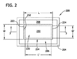
図2、3および4は、それぞれ、例えば、図1に示される炉100のような任意の方向性凝固炉に用いるルツボ200の第1の実施形態の平面図、断面および拡大図を示す。
2, 3 and 4 show a top view, a cross-section and an enlarged view, respectively, of a first embodiment of a
ルツボ200は、底206(概して「第2部分」)と、底から上方に延在している4つの壁204を有する。
Crucible 200 has a bottom 206 (generally a “second portion”) and four
底206と壁204は、一体化して、ともに形成されてよくまたはともに結合されてよく、溶融物111(図1)は、そこに収容される。
The
底206は、上表面208と、下表面210と、上表面と下表面との間で延在している開口220を有する。
The
開口220は、4つの側面222により境界されているルツボ200に形成されているボイドにより規定されている。
The
他の実施形態において、開口220は、長方形以外の形状、例えば、円形、楕円または任意の他の適切な形状であってよく、およびそこに配置されるプレート250は、それに応じて成形される。
In other embodiments, the
開口220は、底206の断面を機械加工するまたはそうでなければ除去することによってルツボ200に形成されてよい。
The
他の実施形態において、開口220を、ルツボ200の製造中に形成してよい。
In other embodiments, the
開口220は、底206の上表面208に隣接した長さLおよび幅Wと、下表面210に隣接した長さL’および幅W’とを有する。
各々の側面222は、ルツボ200の壁204から内側に離れるように傾斜し、長さLは、長さL’よりも大きく、および幅Wは、幅W’よりも大きい。
Each
いくらかの実施形態において、長さL、長さL’、幅W、および幅W’は、50mm〜630mmの間であってよい。 In some embodiments, the length L, length L ′, width W, and width W ′ may be between 50 mm and 630 mm.
図4から更に明らかにわかるように、側面222は、底206の下表面210に対して約45°の角度がつけられている。
As can be seen more clearly from FIG. 4, the
しかしながら、側面222は、実施形態の技術的範囲から逸脱せずに異なる角度に向けられてよい。 However, the side surfaces 222 may be oriented at different angles without departing from the scope of the embodiments.
例えば、いくらかの実施形態において、側面222は、底206の下表面210に対して約35°の角度がつけられてよい。
For example, in some embodiments, the
4つの側面252を有するプレート250(概して、「第1部分」)は、開口220内に配置するための寸法にされている。本発明の実施形態は、ルツボ200の底206にプレート250を配置することを開示しており、付加的なプレートを、壁204のいずれかまたは全ての中に配置できる。更に、いくらかの実施形態において、プレート250を、用いなくてよく、および代わりに、プレート250に類似したプレートを、壁204のいずれかまたは全ての中に配置してよい。
A plate 250 (generally “first portion”) having four

プレート250は、プレート250に隣接したルツボ200の底206の厚さT2と実質的に同じ厚さである厚さT1を有する。いくらかの実施形態において、T1は、5mm〜25mmの間に相当してよく、およびT2は、5mm〜25mmの間に相当してよい。他の実施形態において、プレート250の厚さT1は、底206の厚さT2よりも大きくまたは小さくてよい。図4からわかるように、プレート250は、開口220の側面222に対応する傾斜プロファイルを備えた4つの側面252を有し、プレートは、開口の側面を備えたレジストリ内にある。開口の傾斜側面222は、第1角度を形成し、該第1角度は、プレート250の4つの側面252の傾斜プロファイルにより形成されている第2角度に対して補完的である。従って、開口220の側面222とプレート250の側面252の配置は、プレートの側面を開口の側面に対して押す溶融物111の重量をもたらす。結合剤は、開口220の側面222内のプレート250を更に固定するのに用いてよく、溶融物111は、開口とプレートとの間を通過することができない。
The
いくらかの実施形態において、結合剤は、鋳込成形シリカ化合物256である。図4に示される結合254の寸法と、そこに含まれる鋳込成形シリカ化合物256の量は、説明のためにとても強調されている。ルツボ200の使用の前に、プレート250と底206の下表面210との間の結合254は、テープまたは他材料により封止できる。流体状態の鋳込成形シリカ256は、底206の上表面208に隣接した結合254内に注入される。次いで、流体鋳込成形シリカ256の溶媒は蒸発し、およびシリカが結合フィラーとして残る。ルツボ200は、結合254における鋳込成形シリカ256を固化するのに燃やすことができる。
In some embodiments, the binder is cast
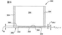
図5および6は、それぞれ、図1に示される炉100のような任意の方向性凝固炉内で用いるルツボ300の第2の実施形態の平面図および断面図を示す。ルツボ300は、底306(概して、「第2部分」)と、底から上方に延在している4つの壁304を有する。底306および壁304は、一体化して、ともに形成またはともに結合でき、溶融物111(図1)は、そこに収容される。底306は、上表面308と下表面310を有する。凹部320は、上表面308に向かって下表面310から上方に延在しているが、底306の上表面308を通過しない。
FIGS. 5 and 6 show a plan view and a cross-sectional view, respectively, of a second embodiment of a
4つの側面352を有するプレート350(概して、「第1部分」)は、凹部320内に配置するための寸法にされている。他の実施形態において、凹部320とプレート250は、長方形でなくてよく、および代わりに、円形、楕円形、または任意の他の適切な形状であってよい。本発明の実施形態は、ルツボ300の底306の凹部320にプレート350を配置することを開示するが、一方で、付加的なプレートは、壁304のいずれかまたは全ての中に配置されてよい。更に、プレート350を用いなくてよく、および代わりに、プレートは、壁304のいずれかまたは全ての中に配置されてよい。
A plate 350 (generally “first portion”) having four
底306の部分360は、ルツボ内に配置されている溶融物からプレート350を分離する。部分360は、溶融物がプレート350を破損、擦り切れまたは腐食するのを防ぐ。いくらかの実施形態によれば、部分360は、1mm〜20mmの間の厚さT部分を有してよく、一方で、プレート350は、1mm〜20mmの間の厚さTプレートを有してよく、および底306は、1mm〜20mmの間の厚さT底を有してよい。更に、プレートの厚さTプレートと部分の厚さT部分は、均一であるように示されるが、厚さは変更できる。プレート350は、底306の部分360により溶融物111から遮断される場合に、プレートは、置換する前に、複数回用いることができる。
A
プレート350は、接着剤または締め具のような任意の結合メカニズムにより底306に取り付けられている。いくらかの実施形態において、プレート360を凹部320に留めるのに、鋳込成形シリカを用いる。他の実施形態において、凹部320とプレート350との間の摩擦適合は、凹部内にプレートを確保する。
他の実施形態において、プレート350は、ルツボ300の底306よりも大きい熱伝導率を有する任意の材料から作られている。例えば、プレート350は、MgO、AlN、SiC、グラファイト、またはMgOとSiC、SiO2とAlN、SiO2とMgO、およびSiO2とTiO2の複合材から作ることができる。更に、プレート350が部分360により溶融物111から遮断されている場合に、別の方法で溶融物と接触するのに適していない材料をその構成に用いることができる(例えば、TiO2)。
In other embodiments, the
図7および8は、それぞれ、図1に示される炉100のような任意の方向性凝固炉内に用いるルツボ400の第3の実施形態の平面図および断面図を示す。ルツボ400は、底406(概して、「第2部分」)と、底から上方に延在している4つの壁404を有する。底406と壁404は、一体化して、ともに形成またはともに結合されてよく、溶融物111(図1)は、そこに収容される。底406は、上表面408と下表面410を有する。
FIGS. 7 and 8 show a top view and a cross-sectional view, respectively, of a third embodiment of a
底406は、増加した熱伝導率の部分450(概して、「第1部分」)を有する。本発明の実施形態は、ルツボ400の底406内に部分450を配置することを開示するが、一方で、付加的な部分は、壁404のいずれかまたは全ての中に配置されてよい。更に、部分450を用いなくてよく、および代わりに増加した熱伝導率の部分は、壁404のいずれかまたは全ての中に配置されている。
The bottom 406 has an increased thermal conductivity portion 450 (generally a “first portion”). While embodiments of the present invention disclose disposing the
部分450は、材料とともに混ぜられる1以上の付加的材料452を含み、底406は、それから作られて複合材を形成する。図7に示されるいくらかの付加的な材料452は、明瞭さのためにかなり減らされており、付加的な材料の相対的な寸法は、同様に、明瞭さのためにかなり拡大されている。付加的な材料452は、底406がそれから作られている材料よりも大きい熱伝導率を有する。従って、増加した熱伝導率を有する底406の部分450の熱伝導率は、概して、底の残りとルツボ400の壁404との熱伝導率よりも大きい3倍〜10倍の範囲である。底の製造中に底406がそれから作られる材料と混合できる任意の材料から、部分450内の付加的な材料452を選択してよい。例えば、付加的な材料452は、MgO、SiC、AlN、またはTiO2のいずれか1つまたは組合せであってよい。
図9、10および11は、それぞれ、図1に示す炉100のような任意の方向性凝固炉に用いるルツボ500の第4の実施形態の平面図、断面図および拡大図を示す。ルツボ500は、底506(概して、「第2部分」)と、底から上方に延在している4つの壁504とを有する。底506と壁504は、一体化して、ともに形成またはともに結合されてよく、溶融物111(図1)は、そこに収容される。底506は、上表面508と下表面510とを有する。開口520は、上表面508と下表面510との間で延在している。
9, 10 and 11 show a top view, a cross-sectional view and an enlarged view, respectively, of a fourth embodiment of a
開口520は、4つの側面522により境界されているルツボ500内に形成されているボイドにより規定されている。開口520は、底506の部分を機械加工するまたはそうでなければ除去することによりルツボ500内に形成できる。他の実施形態において、底の部分を除去せずに開口を形成するように、開口520は、ルツボ500の製造中に形成できる。
底506の部分530は、開口520の側面522から内側におよび壁504から離れるように延在している。部分530は、底表面510から測定される厚さT3を有し、該厚さT3は、底506の厚さT4よりも少ない。部分530は、底506から外側に延在しており、およびレッジ(または棚、ledge)構造を形成している。
A
プレート550(概して、「第1部分」)は、開口520内に配置される寸法にされている。他の実施形態において、開口520およびプレート550は、長方形でなくてよく、および代わりに、円形、楕円形、または任意の他の適切な形状であってよい。本発明の実施形態は、ルツボ500の底506内にプレート550を配置することを開示しており、一方で、付加的なプレートは、壁504のいずれかまたは全ての中に配置されてよい。更に、プレート550を用いなくてよく、および代わりに、プレートは、壁504のいずれかまたは全ての中に配置されてよい。
Plate 550 (generally “first portion”) is dimensioned to be disposed within
プレート550は、プレートの残りから外側に、その周囲に沿って延在しているリップ部分552を有する。リップ部分は、底506の側面522から延在している部分530の幅W2に概ね相当する幅W1を有する。使用中、リップ部分552は、底506の部分530の直接上に配置されている。従って、リップ部分552および底506の部分530は、一体にラップ結合を形成している。従って、プレート550と底506とのラップ結合は、プレートを底と接触させるように押す溶融物111の重量をもたらす。溶融物111が、開口とプレートとの間を通過できないように、開口520内にプレート550を更に固定するのに、結合剤を用いることができる。いくらかの実施形態において、結合剤は、鋳込成形シリカ化合物556である。ルツボ500の使用の前に、プレート550と、底506の下表面510との間の結合554は、テープまたは他材料により封止できる。流体状態の鋳込成形シリカ556は、底506の上表面508に隣接した結合554内に注入される。次いで、流体鋳込成形シリカ556の溶媒は蒸発し、およびシリカは結合フィラーとして残る。従って、ルツボ500は、結合554の鋳込成形シリカ556を固化するように燃やすことができる。
図2〜11の上述したルツボの底の増加した熱伝導率は、個々の底を通過する増加した熱流束(すなわち、熱エネルギーの流れ)をもたらす。ルツボの底を通過する増加した熱流束は、ルツボ内に収容されている溶融物の凝固速度の増加をもたらす。いくらかの実施形態において、凝固速度は、従来のルツボに示されている凝固速度の2倍または3倍増加できる。 The increased thermal conductivity of the crucible bottoms described above in FIGS. 2-11 results in increased heat flux (ie, thermal energy flow) through the individual bottoms. The increased heat flux that passes through the bottom of the crucible results in an increase in the solidification rate of the melt contained in the crucible. In some embodiments, the solidification rate can be increased by a factor of two or three times that shown in conventional crucibles.
溶融物の凝固速度の増加は、溶融物を冷却しおよび凝固したインゴットを成形するのに必要な時間を減少させる。溶融物を形成するのに必要な時間の短縮は、上述したそれらに類似したルツボを用いて方向性凝固炉内でインゴットを製造できる速度(すなわち、生産量)を増加する。 Increasing the solidification rate of the melt reduces the time required to cool the melt and form a solidified ingot. The shortening of the time required to form the melt increases the speed (ie, output) at which ingots can be produced in a directional solidification furnace using crucibles similar to those described above.
図12は、図2〜11に示す任意のルツボを用いて、方向性凝固炉内でインゴットを製造するための例示的な方法600を示す。上述したように、炉は、第1部分(例えば、プレート250、プレート350、部分450、またはプレート550)と第2部分(例えば、底206、底306、底406、または底506)を備えた底を有するルツボを含む。第1部分は、第2部分よりも高い熱伝導率を有する。例示的な実施形態において、第1部分は、第2部分の熱伝導率の少なくとも2倍である熱伝導率を有する。
FIG. 12 shows an
ルツボは、まず、シリコン充填物により充填される。従って、方法600は、シリコン充填物の溶融によりブロック610で開始して、液体溶融物を形成する。ブロック620において、熱は、ルツボの少なくとも底を通して溶融物から移動する。第2部分を通して移動する速度と比較して増加した速度で、第1部分を通して、熱は移動する。溶融物からの熱移動は、溶融物を凝固させてインゴットにする。
The crucible is first filled with a silicon filling. Accordingly, the
本発明は、様々な特定の実施形態に関して説明されるが、一方で、本発明は、特許請求の範囲の精神および技術的範囲内における改良を行うことができるということが認識される。 While the invention will be described in terms of various specific embodiments, it will be appreciated that the invention can be improved within the spirit and scope of the appended claims.
本開示またはその実施形態の要素を導入する場合に、冠詞「a」、「an」、「the」および「said」は、1以上の要素であることを意味することが意図される。用語「comprising」、「including」および「having」は、包含的であり、および記載された要素以外の追加的な要素であってよいことを意味することが意図される。特定の方向(例えば、「頂(top)」、「底(bottom)」、「側面(side)」など)を示唆する用語の使用は、記載の便宜のためであり、および記載される用品の任意の特定の方向を必要とするものではない。 In introducing elements of the present disclosure or embodiments thereof, the articles “a”, “an”, “the” and “said” are intended to mean one or more elements. The terms “comprising”, “including” and “having” are intended to be inclusive and mean that there may be additional elements other than the listed elements. The use of terms that suggest a particular direction (eg, “top”, “bottom”, “side”, etc.) is for convenience of description and is intended for the articles described It does not require any particular direction.
様々な変化は、本開示の技術的範囲から逸脱せずに、上記の構成および方法で為されてよいので、上記に含まれるおよび添付図面に示される全ての事柄は、説明するためであると解釈されるべきであり、制限する意味であるとして解釈されるべきではない。 Various changes may be made in the above configurations and methods without departing from the scope of the present disclosure, so that all matters contained above and shown in the accompanying drawings are for illustrative purposes. It should be interpreted and should not be construed as limiting.
Claims (20)
該ルツボアセンブリが:
溶融物を収容するためのルツボであって、壁と、開口を有する底とを有するルツボ;
ルツボを支持するルツボ支持体、
ルツボを覆う蓋;および
底の開口の中に収められるプレートであって、底の熱伝導率よりも高い熱伝導率を有するプレート
を含む方向性凝固炉。 A directional solidification furnace including a crucible assembly comprising:
The crucible assembly is:
A crucible for containing a melt, the crucible having a wall and a bottom having an opening;
A crucible support for supporting the crucible,
A directional solidification furnace comprising a lid covering the crucible; and a plate housed in an opening in the bottom, the plate having a thermal conductivity higher than the thermal conductivity of the bottom.
該ルツボアセンブリが:
溶融物を収容するためのルツボであって、壁とコンポジット底を含むルツボ;
ルツボを支持するルツボ支持体および、
ルツボを覆う蓋;
を含み、ならびに
コンポジット底が添加剤無しの同等の底よりも高い熱伝導率を有するように、コンポジット底が添加剤を含む、方向性凝固炉。 A directional solidification furnace including a crucible assembly comprising:
The crucible assembly is:
A crucible for containing a melt comprising a wall and a composite bottom;
A crucible support for supporting the crucible, and
A lid covering the crucible;
A directional solidification furnace in which the composite bottom contains additives such that the composite bottom has a higher thermal conductivity than an equivalent bottom without additives.
炉のルツボ内のシリコン充填物を溶融して液体溶融物を形成し、ルツボが、底を含み、底の少なくとも第1部分が、底の第2部分よりも高い熱伝導率を有し;および
ルツボの少なくとも底を通して溶融物から熱を移動し、熱が、第2部分と比較して更に増加した速度で、底の第1部分を通して移動する、
ことを含み、
溶融物からの熱移動が、溶融物の凝固およびインゴットの製造をもたらす、
インゴットの製造方法。 A method for producing an ingot in a directional solidification furnace comprising:
Melting the silicon charge in the furnace crucible to form a liquid melt, the crucible including a bottom, wherein at least a first portion of the bottom has a higher thermal conductivity than a second portion of the bottom; and Transferring heat from the melt through at least the bottom of the crucible and transferring heat through the first portion of the bottom at a further increased rate compared to the second portion;
Including
Heat transfer from the melt results in solidification of the melt and production of ingots,
Ingot manufacturing method.
Applications Claiming Priority (3)
| Application Number | Priority Date | Filing Date | Title |
|---|---|---|---|
| US29913310P | 2010-01-28 | 2010-01-28 | |
| US61/299,133 | 2010-01-28 | ||
| PCT/IB2011/050392 WO2011092659A1 (en) | 2010-01-28 | 2011-01-28 | Crucible for use in a directional solidification furnace |
Publications (2)
| Publication Number | Publication Date |
|---|---|
| JP2013518028A true JP2013518028A (en) | 2013-05-20 |
| JP2013518028A5 JP2013518028A5 (en) | 2014-03-13 |
Family
ID=43858054
Family Applications (1)
| Application Number | Title | Priority Date | Filing Date |
|---|---|---|---|
| JP2012550554A Pending JP2013518028A (en) | 2010-01-28 | 2011-01-28 | Crucible for use in directional solidification furnace |
Country Status (7)
| Country | Link |
|---|---|
| US (1) | US20110180229A1 (en) |
| EP (1) | EP2529043A1 (en) |
| JP (1) | JP2013518028A (en) |
| KR (1) | KR20120128643A (en) |
| CN (1) | CN102741462A (en) |
| TW (1) | TW201202491A (en) |
| WO (1) | WO2011092659A1 (en) |
Families Citing this family (7)
| Publication number | Priority date | Publication date | Assignee | Title |
|---|---|---|---|---|
| TW201245474A (en) * | 2011-05-12 | 2012-11-16 | Hon Hai Prec Ind Co Ltd | Evaporation source device and a coating method using the same |
| FR2979638A1 (en) * | 2011-09-05 | 2013-03-08 | Commissariat Energie Atomique | DEVICE FOR MANUFACTURING CRYSTALLINE MATERIAL FROM A NON-UNIFORM THERMAL RESISTANCE CUP |
| DE102012202589A1 (en) * | 2012-02-21 | 2013-08-22 | Evonik Degussa Gmbh | Use for a crucible |
| CN102808214B (en) * | 2012-08-30 | 2015-06-10 | 天威新能源控股有限公司 | Combined-type protection plate for ingot casting crucible |
| DE102014102980B4 (en) * | 2014-03-06 | 2017-12-21 | Ald Vacuum Technologies Gmbh | Hybrid crucible for the crystallization of materials, use of the hybrid crucible, process for the production of crystalline material and crystalline product |
| US11326271B2 (en) | 2020-02-20 | 2022-05-10 | Globalwafers Co., Ltd. | Methods for forming a unitized crucible assembly |
| US11377751B2 (en) | 2020-02-20 | 2022-07-05 | Globalwafers Co., Ltd. | Crucible molds |
Citations (3)
| Publication number | Priority date | Publication date | Assignee | Title |
|---|---|---|---|---|
| JPH11138512A (en) * | 1997-11-14 | 1999-05-25 | Phoenix:Kk | Box and its manufacture and its apparatus for manufacture |
| JP2006282495A (en) * | 2005-03-10 | 2006-10-19 | Kyocera Corp | Mold and method for manufacturing polycrystalline silicon ingot using same |
| JP2010534179A (en) * | 2007-07-20 | 2010-11-04 | ビーピー・コーポレーション・ノース・アメリカ・インコーポレーテッド | Method and apparatus for producing cast silicon from seed crystals |
Family Cites Families (14)
| Publication number | Priority date | Publication date | Assignee | Title |
|---|---|---|---|---|
| US4015657A (en) * | 1975-09-03 | 1977-04-05 | Dmitry Andreevich Petrov | Device for making single-crystal products |
| US4243471A (en) * | 1978-05-02 | 1981-01-06 | International Business Machines Corporation | Method for directional solidification of silicon |
| US4256530A (en) * | 1978-12-07 | 1981-03-17 | Crystal Systems Inc. | Crystal growing |
| GB2041236A (en) * | 1979-01-18 | 1980-09-10 | Crystal Syst | Method and apparatus for growing crystals |
| GB2084978B (en) * | 1980-09-26 | 1984-07-04 | Crystal Syst | Growing silicon ingots |
| US4764195A (en) * | 1987-05-20 | 1988-08-16 | Corning Glass Works | Method of forming reinforced glass composites |
| DE4022389C2 (en) * | 1990-07-13 | 1995-06-08 | Leybold Ag | Melting and pouring furnace |
| DE4236827A1 (en) * | 1992-10-30 | 1994-05-05 | Wacker Chemitronic | Appts. for prodn. of semiconductor blocks - comprises casting mould with side walls and base, and heater to heat mould |
| US6200385B1 (en) * | 2000-03-20 | 2001-03-13 | Carl Francis Swinehart | Crucible for growing macrocrystals |
| FR2853913B1 (en) * | 2003-04-17 | 2006-09-29 | Apollon Solar | CUTTER FOR A DEVICE FOR MANUFACTURING A BLOCK OF CRYSTALLINE MATERIAL AND METHOD OF MANUFACTURE |
| FR2895749B1 (en) * | 2006-01-04 | 2008-05-02 | Apollon Solar Soc Par Actions | DEVICE AND METHOD FOR MANUFACTURING BLOCK OF CRYSTALLINE MATERIAL |
| EP1811064A1 (en) * | 2006-01-12 | 2007-07-25 | Vesuvius Crucible Company | Crucible for treating molten silicon |
| KR20090023498A (en) * | 2006-06-23 | 2009-03-04 | 알이씨 스캔웨이퍼 에이에스 | Method and crucible for direct solidification of semiconductor grade multi-crystalline silicon ingots |
| US20090314198A1 (en) * | 2006-06-23 | 2009-12-24 | Rec Scanwafer As | Device and method for production of semiconductor grade silicon |
-
2011
- 2011-01-27 US US13/014,932 patent/US20110180229A1/en not_active Abandoned
- 2011-01-28 KR KR1020127022328A patent/KR20120128643A/en not_active Application Discontinuation
- 2011-01-28 EP EP11705697A patent/EP2529043A1/en not_active Withdrawn
- 2011-01-28 WO PCT/IB2011/050392 patent/WO2011092659A1/en active Application Filing
- 2011-01-28 TW TW100103495A patent/TW201202491A/en unknown
- 2011-01-28 CN CN2011800077648A patent/CN102741462A/en active Pending
- 2011-01-28 JP JP2012550554A patent/JP2013518028A/en active Pending
Patent Citations (3)
| Publication number | Priority date | Publication date | Assignee | Title |
|---|---|---|---|---|
| JPH11138512A (en) * | 1997-11-14 | 1999-05-25 | Phoenix:Kk | Box and its manufacture and its apparatus for manufacture |
| JP2006282495A (en) * | 2005-03-10 | 2006-10-19 | Kyocera Corp | Mold and method for manufacturing polycrystalline silicon ingot using same |
| JP2010534179A (en) * | 2007-07-20 | 2010-11-04 | ビーピー・コーポレーション・ノース・アメリカ・インコーポレーテッド | Method and apparatus for producing cast silicon from seed crystals |
Also Published As
| Publication number | Publication date |
|---|---|
| US20110180229A1 (en) | 2011-07-28 |
| KR20120128643A (en) | 2012-11-27 |
| CN102741462A (en) | 2012-10-17 |
| TW201202491A (en) | 2012-01-16 |
| EP2529043A1 (en) | 2012-12-05 |
| WO2011092659A1 (en) | 2011-08-04 |
Similar Documents
| Publication | Publication Date | Title |
|---|---|---|
| JP2013518028A (en) | Crucible for use in directional solidification furnace | |
| KR100984926B1 (en) | Method and apparatus for refining a molten material | |
| JP5855295B2 (en) | Apparatus and method for directional solidification of silicon | |
| CN102888650A (en) | Polycrystalline silicon ingot furnace crucible attemperator for maintaining solid-liquid interface to be horizontal | |
| KR20140086966A (en) | Directional solidification system and method | |
| KR20160026836A (en) | Directional solidification system and method | |
| KR20130113422A (en) | Method and device for producing polycrystalline silicon blocks | |
| JP2013518028A5 (en) | ||
| JP6387018B2 (en) | Cover flux and method for silicon purification | |
| JP2006219313A (en) | Silicon solidifying and refining apparatus and method | |
| TWI532889B (en) | Lining for refractory surfaces for purification of silicon | |
| JP4931432B2 (en) | Molds for the production of polycrystalline silicon slabs | |
| TWI499558B (en) | Reactive cover glass over molten silicon during directional solidification | |
| TWI596066B (en) | Systems for insulating directional solidification furnaces | |
| JP6457549B2 (en) | Hybrid crucible for material crystallization | |
| JP2004149342A (en) | Casting process for silicon | |
| TWI439584B (en) | Casting device for directional solidification |
Legal Events
| Date | Code | Title | Description |
|---|---|---|---|
| A521 | Written amendment |
Free format text: JAPANESE INTERMEDIATE CODE: A523 Effective date: 20140127 |
|
| A621 | Written request for application examination |
Free format text: JAPANESE INTERMEDIATE CODE: A621 Effective date: 20140127 |
|
| A977 | Report on retrieval |
Free format text: JAPANESE INTERMEDIATE CODE: A971007 Effective date: 20140519 |
|
| A131 | Notification of reasons for refusal |
Free format text: JAPANESE INTERMEDIATE CODE: A131 Effective date: 20140708 |
|
| A02 | Decision of refusal |
Free format text: JAPANESE INTERMEDIATE CODE: A02 Effective date: 20150106 |