JP2013504431A - Guide device for strip rolling equipment - Google Patents
Guide device for strip rolling equipment Download PDFInfo
- Publication number
- JP2013504431A JP2013504431A JP2012528271A JP2012528271A JP2013504431A JP 2013504431 A JP2013504431 A JP 2013504431A JP 2012528271 A JP2012528271 A JP 2012528271A JP 2012528271 A JP2012528271 A JP 2012528271A JP 2013504431 A JP2013504431 A JP 2013504431A
- Authority
- JP
- Japan
- Prior art keywords
- guide device
- guide
- piston
- cylinder
- ruler
- Prior art date
- Legal status (The legal status is an assumption and is not a legal conclusion. Google has not performed a legal analysis and makes no representation as to the accuracy of the status listed.)
- Ceased
Links
Images


Classifications
-
- B—PERFORMING OPERATIONS; TRANSPORTING
- B21—MECHANICAL METAL-WORKING WITHOUT ESSENTIALLY REMOVING MATERIAL; PUNCHING METAL
- B21B—ROLLING OF METAL
- B21B39/00—Arrangements for moving, supporting, or positioning work, or controlling its movement, combined with or arranged in, or specially adapted for use in connection with, metal-rolling mills
- B21B39/14—Guiding, positioning or aligning work
-
- B—PERFORMING OPERATIONS; TRANSPORTING
- B21—MECHANICAL METAL-WORKING WITHOUT ESSENTIALLY REMOVING MATERIAL; PUNCHING METAL
- B21C—MANUFACTURE OF METAL SHEETS, WIRE, RODS, TUBES OR PROFILES, OTHERWISE THAN BY ROLLING; AUXILIARY OPERATIONS USED IN CONNECTION WITH METAL-WORKING WITHOUT ESSENTIALLY REMOVING MATERIAL
- B21C47/00—Winding-up, coiling or winding-off metal wire, metal band or other flexible metal material characterised by features relevant to metal processing only
- B21C47/34—Feeding or guiding devices not specially adapted to a particular type of apparatus
- B21C47/3408—Feeding or guiding devices not specially adapted to a particular type of apparatus for monitoring the lateral position of the material
- B21C47/3416—Feeding or guiding devices not specially adapted to a particular type of apparatus for monitoring the lateral position of the material with lateral edge contact
-
- B—PERFORMING OPERATIONS; TRANSPORTING
- B21—MECHANICAL METAL-WORKING WITHOUT ESSENTIALLY REMOVING MATERIAL; PUNCHING METAL
- B21D—WORKING OR PROCESSING OF SHEET METAL OR METAL TUBES, RODS OR PROFILES WITHOUT ESSENTIALLY REMOVING MATERIAL; PUNCHING METAL
- B21D43/00—Feeding, positioning or storing devices combined with, or arranged in, or specially adapted for use in connection with, apparatus for working or processing sheet metal, metal tubes or metal profiles; Associations therewith of cutting devices
- B21D43/02—Advancing work in relation to the stroke of the die or tool
-
- B—PERFORMING OPERATIONS; TRANSPORTING
- B65—CONVEYING; PACKING; STORING; HANDLING THIN OR FILAMENTARY MATERIAL
- B65H—HANDLING THIN OR FILAMENTARY MATERIAL, e.g. SHEETS, WEBS, CABLES
- B65H23/00—Registering, tensioning, smoothing or guiding webs
- B65H23/02—Registering, tensioning, smoothing or guiding webs transversely
- B65H23/032—Controlling transverse register of web
- B65H23/035—Controlling transverse register of web by guide bars
-
- B—PERFORMING OPERATIONS; TRANSPORTING
- B21—MECHANICAL METAL-WORKING WITHOUT ESSENTIALLY REMOVING MATERIAL; PUNCHING METAL
- B21B—ROLLING OF METAL
- B21B2273/00—Path parameters
- B21B2273/04—Lateral deviation, meandering, camber of product
-
- B—PERFORMING OPERATIONS; TRANSPORTING
- B65—CONVEYING; PACKING; STORING; HANDLING THIN OR FILAMENTARY MATERIAL
- B65H—HANDLING THIN OR FILAMENTARY MATERIAL, e.g. SHEETS, WEBS, CABLES
- B65H2301/00—Handling processes for sheets or webs
- B65H2301/40—Type of handling process
- B65H2301/44—Moving, forwarding, guiding material
- B65H2301/442—Moving, forwarding, guiding material by acting on edge of handled material
- B65H2301/4421—Moving, forwarding, guiding material by acting on edge of handled material by abutting edge
-
- B—PERFORMING OPERATIONS; TRANSPORTING
- B65—CONVEYING; PACKING; STORING; HANDLING THIN OR FILAMENTARY MATERIAL
- B65H—HANDLING THIN OR FILAMENTARY MATERIAL, e.g. SHEETS, WEBS, CABLES
- B65H2555/00—Actuating means
- B65H2555/10—Actuating means linear
-
- B—PERFORMING OPERATIONS; TRANSPORTING
- B65—CONVEYING; PACKING; STORING; HANDLING THIN OR FILAMENTARY MATERIAL
- B65H—HANDLING THIN OR FILAMENTARY MATERIAL, e.g. SHEETS, WEBS, CABLES
- B65H2701/00—Handled material; Storage means
- B65H2701/10—Handled articles or webs
- B65H2701/17—Nature of material
- B65H2701/173—Metal
Abstract
本発明は、材料1を加工するための設備における案内装置であって、材料1の長手方向に沿った両側2a、2bで調節することができて互いに平行に配置されたルーラ3a、3bを備えており、それぞれの調節装置4によってルーラ3a、3bに圧力を加えることができる案内装置であって、少なくとも1つの調節装置4が、互いに直列に接続された少なくとも2つの加圧装置4a、4bを備えていることを特徴とする案内装置に関する。 The present invention is a guide device in a facility for processing a material 1, and includes rulers 3a and 3b which can be adjusted on both sides 2a and 2b along the longitudinal direction of the material 1 and are arranged in parallel to each other. Each of the adjusting devices 4 can apply pressure to the rulers 3a, 3b, and at least one adjusting device 4 includes at least two pressurizing devices 4a, 4b connected in series with each other. The present invention relates to a guide device characterized by comprising.
Description
本発明は、材料を加工するための設備における案内装置、特に金属圧延機、好ましくはストリップ圧延機の構成部品としての案内装置に関する。この案内装置は、様々な素材、温度、幅、および厚さを有する様々な材料、特に金属材料のストリップを案内するためのものである。 The present invention relates to a guide device in equipment for processing materials, in particular a guide device as a component of a metal rolling mill, preferably a strip rolling mill. This guiding device is for guiding strips of different materials, in particular metallic materials, having different materials, temperatures, widths and thicknesses.
例えば特許文献1に、圧延機用の案内装置、特に圧延または切断される材料の側部ガイド用の案内装置の構成部品としての案内ルーラ(Fuehrungslineale)が記載されている。この従来技術は、特に、帯状材料を案内する際の案内ルーラの摩耗を取り扱っている。 For example, Patent Document 1 describes a guide ruler as a component of a guide device for a rolling mill, particularly a guide device for a side guide of a material to be rolled or cut. This prior art deals in particular with the wear of the guide ruler when guiding the strip material.
さらに、特許文献2には、ローラテーブル(Rollgang)上を搬送される圧延ストリップ用のそのような側部ガイドを調節するための方法および装置も記載されている。この従来技術でも調節され、ストリップに当接するように圧力を加えられた案内ルーラの摩耗が問題として認識されている。 In addition, US Pat. No. 6,057,059 also describes a method and apparatus for adjusting such a side guide for a rolling strip conveyed on a roller table. In this prior art, wear of the guide ruler, which has been adjusted and pressured to abut the strip, is recognized as a problem.
基本的には、圧延スタンドまたは共通の圧延ラインの入口側および/または出口側で、ストリップが圧延スタンドを通って正しく進むことができることを保証するため、および/またはコイルに対してずれることなくストリップを正しく巻き取ることができることを保証するために、そのような案内ルーラは、各側ごとに、または両側まとめて、ストリップ縁部に対して予め定義された押付力を及ぼすように調節される。 Basically, at the entrance and / or exit side of the rolling stand or common rolling line, to ensure that the strip can travel correctly through the rolling stand and / or without slippage relative to the coil Such a guide ruler is adjusted to exert a pre-determined pressing force against the strip edge, either side by side or together on both sides.
これに関して、特許文献3が、熱間広幅ストリップの仕上げ圧延ラインの入口の前に配置された、圧延方向に対して横方向で移動可能な案内ルーラまたは案内ローラ用の位置決め制御機構を提案する。 In this regard, US Pat. No. 6,057,059 proposes a positioning control mechanism for a guide ruler or guide roller which is arranged in front of the hot rolling strip finish rolling line and is movable transversely to the rolling direction.
同様に、特許文献4にも、ローラテーブル上を搬送される圧延ストリップ用の側部ガイドが開示されており、ここでは、案内ルーラが油圧シリンダによって駆動され、この油圧シリンダはさらに、対応する調節機構によって厳密に位置決めすることができ、その力を調節することができる。
Similarly,
圧延ラインのローラテーブル上、特に鋼板圧延機またはアルミニウム板圧延機などストリップ圧延機のローラテーブル上では、基本的に、様々な温度、幅、および厚さを有する様々な材料からなるストリップを均一かつ確実に案内する必要がある。しかし、それに対応して、材料、その温度、またはその幅および厚さに応じて、この種のストリップ案内機構に要求される押付力も変化する。1つにはストリップの案内を保証し、しかしそれと同時に、ストリップ縁部の変形が生じず、ストリップが全体的に湾曲せず、またはストリップ全体が変形されず、したがってストリップ縁部または案内ルーラに損傷が残らないように配慮すると、案内すべき材料が柔かくなる、高温になる、広くなる、および/または薄くなるにつれて、要求される押付力は小さくなるはずである。 On a roller table of a rolling line, in particular on a roller table of a strip mill such as a steel plate mill or an aluminum plate mill, basically strips of different materials with different temperatures, widths and thicknesses are uniformly and You need to be sure to guide. However, correspondingly, depending on the material, its temperature, or its width and thickness, the pressing force required for this type of strip guide mechanism also changes. One guarantees guiding of the strip, but at the same time no deformation of the strip edge occurs, the strip does not bend entirely, or the entire strip is not deformed, thus damaging the strip edge or the guide ruler Taking care not to remain, the required pressing force should decrease as the material to be guided becomes softer, hotter, wider and / or thinner.
しかし、従来技術から知られている案内ルーラの電気機械式または油圧式の駆動機構は、基本的には、調節可能な最大の押付力になるように設計されており、したがって、例えば柔かい、温度が高い、広い、および/または薄いストリップのためのより低い押付力を調節することができる可能性は技術的に限られている。 However, the electromechanical or hydraulic drive mechanism of the guide ruler known from the prior art is basically designed to be the maximum adjustable pressing force, and thus, for example, soft, temperature The possibility of adjusting the lower pressing force for high, wide and / or thin strips is technically limited.
したがって、本発明の課題は、材料を加工するための設備における案内装置であって、材料の長手方向に沿った両側で調節することができて互いに平行に配置されたルーラを備えており、加工対象の材料の縁部に対して案内ルーラが及ぼす押付力を、最大押付力に比べて明らかに低い圧力であっても確実に調節することができ、したがって案内装置の使用可能な用途を、多様な加工対象材料、特に、柔かい、広い、および/または特に薄い断面の材料、例えば薄いストリップに合わせることができ、それと同時に特に縁部領域におけるストリップの損傷を防止する案内装置を提供することである。 Accordingly, an object of the present invention is a guide device in a facility for processing a material, comprising a ruler that can be adjusted on both sides along the longitudinal direction of the material and arranged parallel to each other. The pressing force exerted by the guide ruler on the edge of the target material can be reliably adjusted even at a pressure that is clearly lower than the maximum pressing force. To provide a guiding device which can be adapted to a particular workpiece material, in particular a soft, wide and / or particularly thin cross-sectional material, for example a thin strip, while at the same time preventing damage to the strip, especially in the edge region .
この課題は、本発明によれば、請求項1に記載の特徴を備えた案内装置によって解決される。本発明の有利な形態は従属請求項で定義する。 According to the invention, this problem is solved by a guide device having the features of claim 1. Advantageous embodiments of the invention are defined in the dependent claims.
本発明は、冒頭に述べた種類の案内装置を取り扱い、そのような案内装置は、例えばストリップ圧延機において、例えばステッケル圧延機や冷間圧延機の逆転式スタンドなど圧延スタンドの入口側および/または出口側、またはタンデム式に配置された圧延スタンドの入口側および/または出口側、特に巻取り装置の前または後ろで使用される。 The present invention deals with a guide device of the kind mentioned at the outset, such a guide device being used, for example, in a strip mill, for example on the inlet side of a rolling stand, such as a reversing stand of a Steckel mill or a cold mill, and / or Used on the exit side or the entrance side and / or exit side of a rolling stand arranged in tandem, in particular before or behind the winding device.
本発明は、考えられるすべての材料の加工、特に金属圧延機またはプラスチック加工ラインで使用することができる。しかし、本発明による案内装置が、仕上げ圧延ライン(いわゆる仕上げ圧延機(Finish Rolling Mill))の少なくとも1つの圧延スタンドの入口側または出口側、または巻取り設備の前に配置されると特に好ましい。 The invention can be used in the processing of all possible materials, in particular metal rolling mills or plastic processing lines. However, it is particularly preferred if the guide device according to the invention is arranged at the entrance or exit side of at least one rolling stand of a finish rolling line (so-called Finish Rolling Mill) or before the winding equipment.
本発明によれば、案内装置においてルーラが配置され、ルーラは、材料の長手方向に沿った両側で調節することができ、互いに平行に配置され、それらのルーラによって、加工装置内で、特に例えば圧延スタンドなど加工装置の間で、加工される材料の心合わせおよび/または位置合わせが行われる。様々な材料断面、好ましくはストリップの寸法に対して案内装置を広範に使用できることを保証するために、少なくとも1つの調節機構によって少なくとも1つのルーラに直接圧力を加えることができる。対応する調節装置によって1つのルーラだけに圧力を加えることができる場合には、その調節装置によって、圧力を加えられたルーラを介して、かつ案内される材料自体を介して、反対側のルーラの調節も行われる。しかし、材料の長手方向に沿った両側でルーラに圧力を直接加えることができる好ましい場合には、それに対応して、各ルーラが専用の調節装置を備える。 According to the invention, a ruler is arranged in the guide device, the ruler can be adjusted on both sides along the longitudinal direction of the material and arranged parallel to each other, by means of these rulers, in particular in the processing device, for example The processing material is centered and / or aligned between processing devices such as rolling stands. In order to ensure that the guide device can be used extensively for various material cross-sections, preferably strip dimensions, it is possible to apply pressure directly to at least one ruler by means of at least one adjustment mechanism. If it is possible to apply pressure to only one ruler by means of a corresponding adjusting device, the adjusting device causes the opposite ruler to pass through the pressure ruler and through the guided material itself. Adjustments are also made. However, in the preferred case where pressure can be applied directly to the ruler on both sides along the length of the material, each ruler is correspondingly equipped with a dedicated adjustment device.
少なくとも1つの調節装置が、より広範な調節可能な圧力にわたって、最大押付力よりも明らかに低い厳密に定義された圧力をもルーラを介して加工対象の材料に加えることができることを保証するために、本発明によれば、少なくとも1つの調節装置が、互いに直列に接続された、したがって互いに協働する少なくとも2つの加圧装置を備えており、これらの加圧装置はまた、場合によっては2つの異なる最大調節圧力を加えることができる。 To ensure that at least one adjusting device can apply a strictly defined pressure, clearly lower than the maximum pressing force, to the material to be processed through the ruler over a wider range of adjustable pressures According to the invention, the at least one adjusting device comprises at least two pressure devices connected in series with each other and thus cooperating with each other, these pressure devices also optionally Different maximum adjustment pressures can be applied.
したがって、互いに直列に接続された加圧装置を適切に選択すると、例えば比較的大きい方の加圧装置と比較的小さな加圧装置を使用することによって、好ましくは、第1の加圧装置によって基本圧力を加えることができ、第2の加圧装置によって、上記の基本圧力に加えて、加工される材料または加工対象の材料に対するルーラの全圧の微調節を行うことができる。 Accordingly, when a pressure device connected in series with each other is appropriately selected, the first pressure device is preferably used, for example, by using a relatively large pressure device and a relatively small pressure device. Pressure can be applied, and the second pressurization device can fine tune the total pressure of the ruler relative to the material being processed or the material being processed, in addition to the basic pressure described above.
加圧装置が少なくとも2つのピストン−シリンダユニットを備えている限り、本発明の特に好ましい実施形態では、比較的小さい方のシリンダが、比較的大きい方のシリンダのピストンロッドに固定されるか、またはピストンロッド内に固定され、好ましくはピストンロッドに組み込まれている。これにより、ピストン−シリンダユニットの特に効果的で確実な直列接続を利用できるようになり、これによってさらに、小さいピストン−シリンダユニットによって付加される圧力が、大きいピストン−シリンダユニットによって付加される圧力に確実に加わることが保証される。この場合、比較的小さい方のピストン−シリンダユニットが、比較的大きい方のピストン−シリンダユニットの最大圧力の最大50%、特に好ましくは最大35%を付加することができると特に好ましい。 In a particularly preferred embodiment of the invention, as long as the pressurization device comprises at least two piston-cylinder units, the smaller cylinder is fixed to the piston rod of the larger cylinder, or It is fixed in the piston rod and is preferably incorporated in the piston rod. This makes it possible to take advantage of a particularly effective and reliable series connection of piston-cylinder units, which further reduces the pressure applied by the small piston-cylinder unit to the pressure applied by the large piston-cylinder unit. Guaranteed to join reliably. In this case, it is particularly preferred if the smaller piston-cylinder unit can add up to 50%, particularly preferably up to 35%, of the maximum pressure of the larger piston-cylinder unit.
本発明による案内装置のさらなる好ましい形態では、複数の加圧装置の連結が機械的に、好ましくは少なくとも1つのラックアンドピニオン機構によって行われる。この好ましい形態により、案内装置内部で向かい側のルーラと平行な各ルーラの確実な調節、および場合によっては加工対象の材料の長手方向に沿った側部に対して完全に垂直な方向での各ルーラの確実な調節を、複数の加圧装置を使用する場合でも特に簡単な手段によって保証することができる。 In a further preferred form of the guide device according to the invention, the connection of the plurality of pressure devices is effected mechanically, preferably by at least one rack and pinion mechanism. With this preferred form, reliable adjustment of each ruler parallel to the opposite ruler within the guide device, and possibly each ruler in a direction completely perpendicular to the longitudinal side of the material to be processed This reliable adjustment can be ensured by particularly simple means even when a plurality of pressure devices are used.
既に冒頭で述べたように、本発明による案内装置は、各ルーラ当たりの加圧装置の数に関して特に限定はないが、互いに直列に接続された2つのピストン−シリンダユニットを備える少なくとも1つの加圧装置が、ルーラの1つのみと接続しているのが好ましい。これにより、本発明による目的を達成するために必要な装備を最小限に抑えられる。しかし、この場合には、例えばストリップの縁部など材料の長手方向に沿った両側に対する加圧は、加工対象の材料が、加圧装置を設けられたルーラによって、その材料の長手方向に沿った反対側の側部に配置されたルーラに押し付けられるときに行われる。 As already mentioned at the outset, the guide device according to the invention is not particularly limited with regard to the number of pressure devices per ruler, but at least one pressure device comprising two piston-cylinder units connected in series with each other. Preferably, the device is connected to only one of the rulers. This minimizes the equipment required to achieve the objectives of the present invention. However, in this case, for example, the pressure applied to both sides along the longitudinal direction of the material such as the edge of the strip is applied along the longitudinal direction of the material by the ruler provided with the pressurizing device. This is done when pressed against a ruler located on the opposite side.
本発明による案内装置内部でルーラを互いに独立して調節することができると好ましい。なぜなら、それにより、加工対象の材料の両側での特に確実なプロセス制御を行うことができるようになるからである。特に、ストリップ幅にわたって厚さが異なるいわゆる連続テーラードブランクの圧延の場合、厚い方のストリップ側部での加圧に比べて、薄い方のストリップ側部に対する加圧を小さくすることで、両側でのストリップ縁部損傷が防止され、それと同時に確実なストリップの案内が行われる。 It is preferred if the rulers can be adjusted independently of one another inside the guide device according to the invention. This is because it makes it possible to perform particularly reliable process control on both sides of the material to be processed. In particular, in the case of rolling so-called continuous tailored blanks with different thicknesses across the strip width, the pressurization on the thinner strip side is reduced compared to the pressurization on the thicker strip side. Strip edge damage is prevented and at the same time reliable strip guidance is provided.
いずれにせよ、調節または制御ユニットが、本発明による案内装置の少なくとも1つの調節装置と接続しているのが好ましい。複数の加圧装置が存在する場合、これらを互いに独立して制御または調節することができることが特に好ましい。これにより、特に好ましい形態では、加工設備において、できるだけ多様な製造物に対し、最大限の自由度のプロセス制御を利用できるようになる。 In any case, it is preferred that the adjustment or control unit is connected to at least one adjustment device of the guide device according to the invention. If there are a plurality of pressure devices, it is particularly preferred that they can be controlled or adjusted independently of each other. This makes it possible in a particularly preferred form to utilize the maximum degree of freedom of process control for as many different products as possible in the processing facility.
本発明によれば、材料に対して垂直な方向での1つまたは複数のルーラの調節は、それぞれの調節装置の同期制御および調節のみによって行うことができる。しかし、材料に対して垂直な方向での1つまたは複数のルーラの調節を少なくとも1つの追加の案内レールが補助する実施形態が好ましい。少なくとも1つの調節装置がそれぞれのルーラの端部領域に提供され、これらの調節装置の間にそれぞれ1つの案内レールが配置されると特に好ましい。これにより、垂直から角度が傾いて材料に対してずれるルーラのずれが、確実に、特に簡単な手段によって妨げられる。 According to the invention, the adjustment of one or more rulers in the direction perpendicular to the material can be effected only by the synchronous control and adjustment of the respective adjustment device. However, embodiments in which at least one additional guide rail assists in adjusting the one or more rulers in a direction perpendicular to the material are preferred. It is particularly preferred if at least one adjusting device is provided in the end region of the respective ruler and one guide rail is arranged between these adjusting devices. This ensures that the displacement of the ruler, which is inclined with respect to the material at an angle from the vertical, is prevented, in particular by simple means.
以下、本発明を、本発明の異なる実施形態の3つの概略図を参照しながら説明する。しかし、その際、図示は説明のためのものにすぎず、添付の特許請求の範囲で定義する本発明の保護範囲を何らかの形で限定する意図のものではない。 The invention will now be described with reference to three schematic diagrams of different embodiments of the invention. However, the illustrations are for illustration purposes only and are not intended to limit the protection scope of the invention as defined in the appended claims in any way.
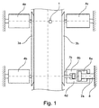
図1に、材料1を案内するための本発明による案内装置の概略上面図を示す。材料1の長手方向に沿った両側にルーラ3aおよび3bが配置され、ルーラ3aおよび3bはそれぞれ、それらの端部領域に配置された2つの調節装置4a、4bおよび4c、4dによって材料1に対して調節することができる。材料1の長手方向に沿った縁部に対する圧力は、制御および調節することができ、予め定められており、ルーラ3a、3bによって、定められた大きさに調節することができる。説明のために、調節装置4dのみを概略図で詳細に示す。しかし、図1に示す第1の実施形態によれば、調節装置4a〜4dはすべて同様に構成される。調節装置4a〜4dは、大きさの異なる2つのシリンダ空間6aおよび6bを有する二重シリンダの形態で示されており、ここで、比較的大きい方のシリンダ空間6a内には、ピストンロッド7aが摺動可能に配置され、このピストンロッド7aは油圧機構(図示せず)によって調節および制御することができ、比較的小さい方のシリンダ空間6b内には、同様に、比較的小さい方のピストンロッド7bが摺動可能に配置され、このピストンロッド7bは油圧機構(図示せず)によって調節および制御することができる。大きいピストンロッド7aは基部8に固定され、一方、小さいピストンロッド7bはルーラ3bと接続している。図示される実施形態では、例えば小さいピストンロッド7bが二重シリンダ内へストロークエンドまで進められたときに、大きいピストン−シリンダユニット6a、7aによって二重シリンダの最大圧力が予め定められる。互いに直列に接続されたピストン−シリンダユニット4d、7bと4d、7aの追加によって、大きいピストン7aが二重シリンダ4d内へストロークエンドまで進められたときに、比較的小さい方のピストン−シリンダユニット4d、7bのみによって微調節できるようにして、調節装置4dのより小さい圧力の厳密な調節が行われる。
FIG. 1 shows a schematic top view of a guiding device according to the invention for guiding a material 1. The
図2に、本発明による案内装置の第2の実施形態を示す。この実施形態は、図1に示した第1の実施形態と以下の点のみが異なる。すなわち、ルーラ3aと協働する一対の調節装置4aと4bとの間、および第2のルーラ3bと協働する一対の調節装置4cと4dとの間に、それぞれ案内レール5a、5bが配置され、案内レール5a、5bは、独立して、材料1の長手方向に沿った縁部それぞれに対して垂直な方向でのそれぞれのルーラ3a、3bの移動を可能にする。
FIG. 2 shows a second embodiment of the guide device according to the present invention. This embodiment differs from the first embodiment shown in FIG. 1 only in the following points. That is, the
最後に、図3に、本発明による案内装置の第3の実施形態を示す。この実施形態では、それぞれのルーラ3a、3bに、それぞれ1つの調節装置4a、4bのみが接続され、図1および図2による実施形態とは異なり、ルーラ3a、3bのほぼ中央に、ルーラ3a、3bの長さの半分の位置に配置される。ストリップ材料1の長手方向に沿った縁部に対して垂直な方向でのルーラ3a、3bそれぞれの移動を保証するために、ルーラ3a、3bのそれぞれの端部の領域に、案内レール5a、5bまたは5c、5dが、それぞれの調節装置4a、4bの両側に対として配置される。本発明による案内装置のこの第3の実施形態でも、調節装置4a、4bは、図1で既に詳細に論じた大きいピストンロッド7aと小さいピストンロッド7bをそれぞれ備える二重シリンダからなる。
Finally, FIG. 3 shows a third embodiment of the guiding device according to the present invention. In this embodiment, only one
Claims (14)
少なくとも1つの調節装置(4)が、相前後して直列に接続された少なくとも2つの加圧装置(4a、4b)を備えていることを特徴とする案内装置。 Guide device in a facility for processing the material (1), which can be adjusted on both sides (2a, 2b) along the longitudinal direction of the material (1) and arranged in parallel with each other (3a 3b), which can apply pressure to at least one ruler (3a, 3b) by means of at least one adjusting device (4),
Guide device, characterized in that at least one adjusting device (4) comprises at least two pressurizing devices (4a, 4b) connected in series one after the other.
Applications Claiming Priority (3)
| Application Number | Priority Date | Filing Date | Title |
|---|---|---|---|
| DE102009041453A DE102009041453A1 (en) | 2009-09-12 | 2009-09-12 | Guiding device for a strip rolling mill |
| DE102009041453.3 | 2009-09-12 | ||
| PCT/EP2010/005547 WO2011029599A1 (en) | 2009-09-12 | 2010-09-09 | Guide device for a strip rolling mill |
Publications (2)
| Publication Number | Publication Date |
|---|---|
| JP2013504431A true JP2013504431A (en) | 2013-02-07 |
| JP2013504431A5 JP2013504431A5 (en) | 2014-04-03 |
Family
ID=43533116
Family Applications (1)
| Application Number | Title | Priority Date | Filing Date |
|---|---|---|---|
| JP2012528271A Ceased JP2013504431A (en) | 2009-09-12 | 2010-09-09 | Guide device for strip rolling equipment |
Country Status (9)
| Country | Link |
|---|---|
| US (1) | US20120174647A1 (en) |
| EP (1) | EP2475472A1 (en) |
| JP (1) | JP2013504431A (en) |
| KR (1) | KR101421978B1 (en) |
| CN (1) | CN102497943A (en) |
| DE (1) | DE102009041453A1 (en) |
| RU (1) | RU2507018C2 (en) |
| SA (1) | SA110310692B1 (en) |
| WO (1) | WO2011029599A1 (en) |
Cited By (1)
| Publication number | Priority date | Publication date | Assignee | Title |
|---|---|---|---|---|
| CN104174700A (en) * | 2014-07-07 | 2014-12-03 | 芜湖市海联机械设备有限公司 | Oil-pressure automatic flattening and guiding device of reeling machine |
Families Citing this family (8)
| Publication number | Priority date | Publication date | Assignee | Title |
|---|---|---|---|---|
| DE102009014099A1 (en) * | 2008-10-28 | 2010-04-29 | Sms Siemag Aktiengesellschaft | Device and method for lateral guidance of a rolled strip transported on a roller table |
| CN102699135B (en) * | 2012-05-03 | 2015-09-09 | 本钢板材股份有限公司 | The method of adjustment coiler pinch-roll flipper guide pressure |
| CN105197659A (en) * | 2015-08-26 | 2015-12-30 | 蚌埠市高德机械自动化科技有限公司 | Automatic cloth ironing machine of filter element plate of filter |
| CN106216434B (en) * | 2016-08-16 | 2017-11-14 | 山西太钢不锈钢股份有限公司 | Lead control method in a kind of coiling machine coil process side |
| CN106734680A (en) * | 2016-11-22 | 2017-05-31 | 上海振华重工(集团)股份有限公司 | The lateral alignment device of veneer reeling machine |
| CN108285058B (en) * | 2017-12-25 | 2020-06-19 | 安徽玄同机电科技有限公司 | Guide supporting mechanism for rewinding device of strips |
| EP3552723A1 (en) * | 2018-04-12 | 2019-10-16 | Primetals Technologies Austria GmbH | Device and method for guiding metal strips with grinding bodies having a carrier member |
| CN109624493A (en) * | 2018-12-06 | 2019-04-16 | 山东玫姿蓝家纺有限公司 | Printing device is used in a kind of processing of woollen blanket |
Citations (4)
| Publication number | Priority date | Publication date | Assignee | Title |
|---|---|---|---|---|
| JPS61108415A (en) * | 1984-10-31 | 1986-05-27 | Kawasaki Steel Corp | Method for controlling side guide of steel sheet in hot continuous rolling line |
| JPH0441013A (en) * | 1990-06-07 | 1992-02-12 | Ishikawajima Harima Heavy Ind Co Ltd | Method and device for setting width of side guide |
| JPH08174063A (en) * | 1994-12-26 | 1996-07-09 | Nippon Steel Corp | Method for controlling centering of steel strip |
| JPH10192942A (en) * | 1997-01-17 | 1998-07-28 | Nippon Yakin Kogyo Co Ltd | Side guide device of rolling machine |
Family Cites Families (15)
| Publication number | Priority date | Publication date | Assignee | Title |
|---|---|---|---|---|
| NL291459A (en) * | 1962-04-16 | |||
| DE1427923B2 (en) | 1965-06-10 | 1970-05-27 | Klöckner-Werke AG, 4100 Duisburg | Guide rulers for rolling mills for guiding the width of rolled or cut strip material |
| DE3116278A1 (en) * | 1981-04-24 | 1982-11-11 | Betriebsforschungsinstitut VDEh - Institut für angewandte Forschung GmbH, 4000 Düsseldorf | DEVICE FOR CONTROLLING THE POSITION OF THE TAPE ROLL WHILE ROLLING |
| DE3423560A1 (en) | 1984-06-27 | 1986-01-09 | SMS Schloemann-Siemag AG, 4000 Düsseldorf | POSITIONING CONTROL DEVICE FOR BEFORE THE INPUT OF WARM BROADBAND FINISHING ROLLING MILLS, CROSS-SLIDING GUIDE LINEAL OR. LEADERSHIP ROLES |
| DE4003717C2 (en) | 1990-02-08 | 1999-05-06 | Schloemann Siemag Ag | Lateral guide for rolled strip transported on a roller table |
| JPH0669582B2 (en) * | 1990-10-23 | 1994-09-07 | 石川島播磨重工業株式会社 | Side guide control method |
| DE69207545T2 (en) * | 1991-10-18 | 1996-08-29 | Inst Tech Precision Eng | Index feed system |
| DE4140784C2 (en) | 1991-12-06 | 1993-11-04 | Preussag Stahl Ag | METHOD AND DEVICE FOR REGULATING THE PRESSURE PRESSURE OF A GUIDE LINEAL FOR ROLLING ROLLS TRANSPORTED ON A ROLLER |
| JPH0771687B2 (en) * | 1993-04-19 | 1995-08-02 | 寿産業株式会社 | Rolling guide method for roller guides |
| JPH11123434A (en) * | 1997-10-16 | 1999-05-11 | Ishikawajima Harima Heavy Ind Co Ltd | Method and device for guiding rolled stock with its sides |
| IT1296906B1 (en) * | 1997-12-24 | 1999-08-02 | Abb Sistemi Ind Spa | DEVICE FOR ADJUSTING THE TAPE INPUT GUIDES IN A ROLLING MILL |
| KR100306703B1 (en) * | 1997-12-29 | 2001-10-19 | 이구택 | Automatic feedback position controlling side guide |
| RU2197349C2 (en) * | 1999-01-25 | 2003-01-27 | Закрытое акционерное общество "Новокраматорский машиностроительный завод" | Method for laterally guiding strip continuously moved by means of roller table, mainly from stand to coiler for further coiling it |
| JP3766576B2 (en) * | 2000-02-08 | 2006-04-12 | 新日本製鐵株式会社 | Material centering method in hot width reduction press |
| CN201046468Y (en) * | 2007-06-15 | 2008-04-16 | 中国第一重型机械集团公司 | Strong forced pushing bed |
-
2009
- 2009-09-12 DE DE102009041453A patent/DE102009041453A1/en not_active Withdrawn
-
2010
- 2010-09-09 JP JP2012528271A patent/JP2013504431A/en not_active Ceased
- 2010-09-09 EP EP10754286A patent/EP2475472A1/en not_active Withdrawn
- 2010-09-09 US US13/393,849 patent/US20120174647A1/en not_active Abandoned
- 2010-09-09 RU RU2012114324/02A patent/RU2507018C2/en not_active IP Right Cessation
- 2010-09-09 WO PCT/EP2010/005547 patent/WO2011029599A1/en active Application Filing
- 2010-09-09 CN CN2010800415457A patent/CN102497943A/en active Pending
- 2010-09-09 KR KR1020127007447A patent/KR101421978B1/en not_active IP Right Cessation
- 2010-09-18 SA SA110310692A patent/SA110310692B1/en unknown
Patent Citations (4)
| Publication number | Priority date | Publication date | Assignee | Title |
|---|---|---|---|---|
| JPS61108415A (en) * | 1984-10-31 | 1986-05-27 | Kawasaki Steel Corp | Method for controlling side guide of steel sheet in hot continuous rolling line |
| JPH0441013A (en) * | 1990-06-07 | 1992-02-12 | Ishikawajima Harima Heavy Ind Co Ltd | Method and device for setting width of side guide |
| JPH08174063A (en) * | 1994-12-26 | 1996-07-09 | Nippon Steel Corp | Method for controlling centering of steel strip |
| JPH10192942A (en) * | 1997-01-17 | 1998-07-28 | Nippon Yakin Kogyo Co Ltd | Side guide device of rolling machine |
Cited By (2)
| Publication number | Priority date | Publication date | Assignee | Title |
|---|---|---|---|---|
| CN104174700A (en) * | 2014-07-07 | 2014-12-03 | 芜湖市海联机械设备有限公司 | Oil-pressure automatic flattening and guiding device of reeling machine |
| CN104174700B (en) * | 2014-07-07 | 2016-01-27 | 芜湖市海联机械设备有限公司 | A kind of volume oil pressure flattens guider automatically |
Also Published As
| Publication number | Publication date |
|---|---|
| EP2475472A1 (en) | 2012-07-18 |
| RU2507018C2 (en) | 2014-02-20 |
| KR101421978B1 (en) | 2014-07-22 |
| SA110310692B1 (en) | 2014-08-04 |
| WO2011029599A1 (en) | 2011-03-17 |
| KR20120062817A (en) | 2012-06-14 |
| US20120174647A1 (en) | 2012-07-12 |
| DE102009041453A1 (en) | 2011-03-24 |
| CN102497943A (en) | 2012-06-13 |
| RU2012114324A (en) | 2013-10-20 |
Similar Documents
| Publication | Publication Date | Title |
|---|---|---|
| JP2013504431A (en) | Guide device for strip rolling equipment | |
| JP2013504431A5 (en) | ||
| EP3150294B1 (en) | Cut-to-length steel coil processing line with stretcher leveler and temper mill and method | |
| EP2213387A1 (en) | Magnesium alloy hot-rolling mill | |
| WO2010037731A3 (en) | System for cold roll profiling profiles having variable cross-sections | |
| RU2741942C1 (en) | Systems and methods for controlling flatness of metal substrate using low pressure rolling | |
| EP3370891B1 (en) | Bending method | |
| BR0214598A (en) | Procedure and Device for Controlled Grinding and Cooling a Wide Strip of Metal Leaving a Rolling Train for Hot Rolled Strips, Especially Steel Strips or Sheets | |
| EP3205415A1 (en) | Method for producing metal plate with protruding ridge, metal plate with protruding ridge, and structural component | |
| JP2011527634A (en) | Method for guiding the longitudinal direction of a rolled product, in particular a hot-rolled steel strip, and a hot rolling mill for carrying out this method | |
| US9056345B2 (en) | Method and profiling installation for roll forming a sheet metal | |
| US5218848A (en) | Method and apparatus for correcting a widthwise bend in an end portion of a hot-rolled sheet-shaped product | |
| US10207304B2 (en) | Bending device for metallic plate | |
| KR20160139243A (en) | Sheet heating apparatus for flexible roll forming system | |
| DK2933033T3 (en) | METHOD FOR MAKING A FLAT METAL PLATE | |
| EP1786577B1 (en) | Method for milling a metal strip | |
| US20100162784A1 (en) | Flattening device | |
| EP0442645B1 (en) | Method and apparatus for correcting a widthwise bend in an end portion of a hot-rolled sheet-shaped product | |
| JP2013505139A (en) | Modular guide device | |
| JP6479556B2 (en) | Rolling device, bending method | |
| JP2013505139A5 (en) | ||
| KR100939269B1 (en) | Reversing Mill | |
| US3459027A (en) | Method for levelling sheet stock | |
| JP6304498B2 (en) | Camber suppression method in hot slab sizing press | |
| BE903998A (en) | METHOD FOR COMBINED STRETCHING AND HIGH-RIGHT DIRECTION IN A PLATFORM MACHINE WORK, AND AN APPARATUS FOR CARRYING OUT THIS METHOD |
Legal Events
| Date | Code | Title | Description |
|---|---|---|---|
| A977 | Report on retrieval |
Free format text: JAPANESE INTERMEDIATE CODE: A971007 Effective date: 20130920 |
|
| A131 | Notification of reasons for refusal |
Free format text: JAPANESE INTERMEDIATE CODE: A131 Effective date: 20131015 |
|
| A601 | Written request for extension of time |
Free format text: JAPANESE INTERMEDIATE CODE: A601 Effective date: 20140114 |
|
| A602 | Written permission of extension of time |
Free format text: JAPANESE INTERMEDIATE CODE: A602 Effective date: 20140121 |
|
| A524 | Written submission of copy of amendment under article 19 pct |
Free format text: JAPANESE INTERMEDIATE CODE: A524 Effective date: 20140213 |
|
| A521 | Request for written amendment filed |
Free format text: JAPANESE INTERMEDIATE CODE: A523 Effective date: 20140214 |
|
| A01 | Written decision to grant a patent or to grant a registration (utility model) |
Free format text: JAPANESE INTERMEDIATE CODE: A01 Effective date: 20141029 |
|
| A045 | Written measure of dismissal of application [lapsed due to lack of payment] |
Free format text: JAPANESE INTERMEDIATE CODE: A045 Effective date: 20150225 |