EP3552723A1 - Device and method for guiding metal strips with grinding bodies having a carrier member - Google Patents
Device and method for guiding metal strips with grinding bodies having a carrier member Download PDFInfo
- Publication number
- EP3552723A1 EP3552723A1 EP18166960.7A EP18166960A EP3552723A1 EP 3552723 A1 EP3552723 A1 EP 3552723A1 EP 18166960 A EP18166960 A EP 18166960A EP 3552723 A1 EP3552723 A1 EP 3552723A1
- Authority
- EP
- European Patent Office
- Prior art keywords
- wear
- metal strip
- leading
- metal
- wear body
- Prior art date
- Legal status (The legal status is an assumption and is not a legal conclusion. Google has not performed a legal analysis and makes no representation as to the accuracy of the status listed.)
- Withdrawn
Links
Images

Classifications
-
- B—PERFORMING OPERATIONS; TRANSPORTING
- B21—MECHANICAL METAL-WORKING WITHOUT ESSENTIALLY REMOVING MATERIAL; PUNCHING METAL
- B21B—ROLLING OF METAL
- B21B1/00—Metal-rolling methods or mills for making semi-finished products of solid or profiled cross-section; Sequence of operations in milling trains; Layout of rolling-mill plant, e.g. grouping of stands; Succession of passes or of sectional pass alternations
- B21B1/22—Metal-rolling methods or mills for making semi-finished products of solid or profiled cross-section; Sequence of operations in milling trains; Layout of rolling-mill plant, e.g. grouping of stands; Succession of passes or of sectional pass alternations for rolling plates, strips, bands or sheets of indefinite length
-
- B—PERFORMING OPERATIONS; TRANSPORTING
- B21—MECHANICAL METAL-WORKING WITHOUT ESSENTIALLY REMOVING MATERIAL; PUNCHING METAL
- B21B—ROLLING OF METAL
- B21B39/00—Arrangements for moving, supporting, or positioning work, or controlling its movement, combined with or arranged in, or specially adapted for use in connection with, metal-rolling mills
- B21B39/14—Guiding, positioning or aligning work
-
- B—PERFORMING OPERATIONS; TRANSPORTING
- B65—CONVEYING; PACKING; STORING; HANDLING THIN OR FILAMENTARY MATERIAL
- B65H—HANDLING THIN OR FILAMENTARY MATERIAL, e.g. SHEETS, WEBS, CABLES
- B65H23/00—Registering, tensioning, smoothing or guiding webs
- B65H23/02—Registering, tensioning, smoothing or guiding webs transversely
- B65H23/032—Controlling transverse register of web
- B65H23/0322—Controlling transverse register of web by acting on edge regions of the web
-
- B—PERFORMING OPERATIONS; TRANSPORTING
- B65—CONVEYING; PACKING; STORING; HANDLING THIN OR FILAMENTARY MATERIAL
- B65H—HANDLING THIN OR FILAMENTARY MATERIAL, e.g. SHEETS, WEBS, CABLES
- B65H2403/00—Power transmission; Driving means
- B65H2403/40—Toothed gearings
- B65H2403/46—Toothed gearings worm gearing
-
- B—PERFORMING OPERATIONS; TRANSPORTING
- B65—CONVEYING; PACKING; STORING; HANDLING THIN OR FILAMENTARY MATERIAL
- B65H—HANDLING THIN OR FILAMENTARY MATERIAL, e.g. SHEETS, WEBS, CABLES
- B65H2404/00—Parts for transporting or guiding the handled material
- B65H2404/70—Other elements in edge contact with handled material, e.g. registering, orientating, guiding devices
- B65H2404/72—Stops, gauge pins, e.g. stationary
- B65H2404/721—Stops, gauge pins, e.g. stationary adjustable
-
- B—PERFORMING OPERATIONS; TRANSPORTING
- B65—CONVEYING; PACKING; STORING; HANDLING THIN OR FILAMENTARY MATERIAL
- B65H—HANDLING THIN OR FILAMENTARY MATERIAL, e.g. SHEETS, WEBS, CABLES
- B65H2555/00—Actuating means
- B65H2555/10—Actuating means linear
- B65H2555/12—Actuating means linear hydraulic
-
- B—PERFORMING OPERATIONS; TRANSPORTING
- B65—CONVEYING; PACKING; STORING; HANDLING THIN OR FILAMENTARY MATERIAL
- B65H—HANDLING THIN OR FILAMENTARY MATERIAL, e.g. SHEETS, WEBS, CABLES
- B65H2701/00—Handled material; Storage means
- B65H2701/10—Handled articles or webs
- B65H2701/13—Parts concerned of the handled material
- B65H2701/131—Edges
- B65H2701/1315—Edges side edges, i.e. regarded in context of transport
-
- B—PERFORMING OPERATIONS; TRANSPORTING
- B65—CONVEYING; PACKING; STORING; HANDLING THIN OR FILAMENTARY MATERIAL
- B65H—HANDLING THIN OR FILAMENTARY MATERIAL, e.g. SHEETS, WEBS, CABLES
- B65H2701/00—Handled material; Storage means
- B65H2701/10—Handled articles or webs
- B65H2701/17—Nature of material
- B65H2701/173—Metal
Definitions
- the application relates to a device for lateral guidance of a metal belt running on a metal belt conveyor belt with wear bodies and a method thereof.
- the metal belt conveyor may be, for example, a finishing train.
- the metal belt conveyor can be an area in front of or between the rolling stands in the direction of strip travel, or an area in front of a coiler.
- a metal band is used for example in WO2015043926 and EP17174195.2 by Schlenfinelasticity, which are arranged in a main body module, laterally guided. Guiding is carried out by leading contacting the leading metal strip with the wear surface of a wear body. In such devices for lateral guidance, it is advantageous if the wear body repeatedly exposed by rotation about a rotation axis fresh areas a management-related wear by the metal strip to be guided.
- a Device for the lateral guidance of a metal belt running on a metal belt conveyor comprising at least one base module with a guide level and at least one wear body with a wear surface for leading contacting the metal strip to be guided, wherein the wear body is rotatable about an axis perpendicular to the guide plane rotation axis, characterized that at least one carrier element is present, wherein the wear body is attached to the carrier element or the wear body comprises the carrier element, and the carrier element is mounted displaceably and rotatably in the base body module in the direction of the axis of rotation.
- the carrier element can be mounted directly in the main body module or indirectly, that is in a further component, which is arranged in the main body module.
- the carrier element may, for example, be a shaft - with a round or different cross-section - of a rotary drive for rotating the wear body.
- the metal belt conveyor may be, for example, a finishing train. It can be seen in the strip running direction to an area before or between the rolling stands, or an area in front of a coiler.
- the finishing train may be a hot strip mill or other types of rolling mill for producing metal strip.
- the metal strip may be a hot-rolled metal strip.
- the metal strip may be, for example, a steel strip or an aluminum strip.
- the wear body is rotatable about an axis of rotation perpendicular to the guide plane; this runs, for example, through a SchlauerAvemwelle, through which the force is guided for rotating, for example, from a rotary drive to the wear body. Minor deviations from vertical arrangement are here included, so the position of the guide plane and axis of rotation is thus to be understood as substantially perpendicular.
- the position of a wear body in relation to the management level can be changed. This can be used to extend the service life of a wear body. A wear body whose wear surface has already been ground down on the surface is pushed, for example, around the worn track. As long as still wearable material is present on the wear surface, this process can be repeated. An exchange of wear bodies must therefore be made later than in a conventional mode in which the position of the wear body in relation to the management level can not be changed by displacement. Until replacement is required, more material can be worn away from the wear surface. An adjustment by moving the support element can for example be done manually, mechanically and / or hydraulically.
- At least one adjusting device for moving the carrier element present in the apparatus for laterally guiding a running over a metal belt conveyor metal strip.
- it is a hydraulic adjusting device.
- the carrier element may be part of the adjusting device; For example, in a hydraulic adjustment of the cylinder piston.
- the lateral guidance device for laterally guiding a metal belt running over a metal belt conveyor, there is also a device for measuring lateral guidance from the metal band to the wear body and or from the wearer body to the metal band acting force available.
- the force measurement makes it possible to determine whether a displacement for approaching or removing the wear surface to the edge of the metal strip is favorable. Force measurement takes place, for example, via the pressure prevailing in hydraulic cylinders.
- a device for controlling the lateral guidance from the metal band to the wear body and or from the wearer body to the metal band acting force available can be controlled by contact.
- the hydraulic adjusting device for displacing the carrier element comprises at least one hydraulic cylinder and a device for measuring and / or regulating its cylinder travel.
- a hydraulic adjusting device is easier to handle and offers with respect to adjustment of the wearer of the metal body on the forces acting forces simpler adjustment options and a force and pressure-controlled tape guide.
- a force and pressure-controlled tape guide is also possible there.
- the adjusting device is supported on the main body module.
- forces acting on the metal band from the metal band on the wear body and / or the wear body are finally introduced into the main body module.
- an adjusting device for moving the main body module is present. Then, the position of a wear body in relation to the management level by moving the main body module can be changed.
- the hydraulic adjusting device for displacing the basic body module forces acting at least one hydraulic cylinder, and optionally a device for measuring and / or regulating its cylinder travel.
- a hydraulic adjusting device is easier to handle and offers with respect to adjustment of the wearer of the metal body on the forces acting forces easier adjustment and a force and pressure-controlled tape guide.
- the wear body rotatable about the rotation axis is rotatable in a plurality of rotational positions, the wear surface being substantially parallel to the guide plane in all rotational positions, and the guide plane of the body module being substantially orthogonal to the conveying direction of the metal tape to be guided.
- the wear surface is the surface intended for guidance. This can be a surface before it leads and wears out. It can also be an area that has already been sanded down by previously occurring wear and is used again for guidance.
- the wear body is a, preferably round, disc with a flat wear surface.
- Another object of the present application is a method for lateral guidance of a metal belt conveyor running metal bands, comprising at least one base module with a management level and at least one wear body with a Schlmony constitution for leading contacting the leading metal strip, the Schlauerharm to one to the management level vertical axis of rotation is rotatable, characterized in that the position of the wear body in relation to the guide plane by displacing a support element to which the wear body is attached or which comprises the wear body, is changed, prior to leading a first metal strip, and / or while leading a first metal strip, and / or in a period after the leading contact of a first metal strip and before the leading contacting of a second metal strip.
- a device according to the invention for the lateral guidance of a running on a metal belt conveyor metal strip can be operated.
- the position of the wear body in relation to the management level by moving a support element to which the wear body is attached or which comprises the wear body changed.
- the change of a pre-existing state can be done before a first metal strip enters the guide device - for example, because the pre-existing state was selected for metal strips of other dimensions.
- the change can also take place during the leading contacting of a first metal strip, for example, because findings arise that make an adjustment appear meaningful.
- the change can also be made after leading a first metal strip and before leading a second metal strip - for example, because the first metal strip has other dimensions, or it has been found that approaching the edge of the metal strip is favorable for a tidier guide.
- the inventive method allows extended use of wear bodies and reduced replacement requirements.
- the position of the wear body in relation to the leadership level depending on the size of the force chosen from the metal band to the wear body and or from the wearer body to the metal band acts or is expected for another metal band. This allows to control the extent of wear and to ensure good guidance.
- the inventive method allows extended use of wear bodies and reduced replacement requirements.
- the position of the main body module in relation to the wear surface by moving the base body module changed while leading a metal strip, or in a period after the leading contact of a first metal strip and before the leading contact of another metal strip.
- the inventive method allows extended use of wear bodies and reduced replacement requirements.
- At least one wear body is adjusted in a pressure-controlled manner to the metal band for guidance by means of a hydraulic adjusting device supported on the main body module. This allows to control the level of leadership while the tape is being guided and to allow controlled guidance.
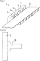
- FIG. 1 shows a section of a device 1 for lateral guidance schematically in an oblique view. Shown is a metal band 2, which runs over a roller table.
- Basic body module 3 has a guide level 4 and a plurality of wear bodies, of which only the wear surfaces 5a, 5b, 5c are shown.
- the wear bodies are rotatable about axes of rotation perpendicular to the guide plane.
- the wear surfaces are preferably flat, as in the WO2015043926 and EP17174195.2 is set forth.
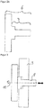
- FIG. 2a schematically shows a Schlcken stresses 6, to which a support member 7 is attached.
- FIG. 2b shows schematically in to FIG. 2a analogous representation of a wear body 6, which comprises the carrier element 7.
- FIG. 3 shows in one too FIG. 2a analog representation of how the support member 8 in the base module 9 in the direction of axis of rotation is displaceable - indicated by a double arrow.
- the support member 8 is rotatably mounted in the main body module.
- FIG. 4 indicates by analogy FIG. 3 in that a hydraulic adjusting device 11 for displacing the carrier element is present. It is supported on the base body module 12. The optional device for measuring and / or regulating the cylinder path 13 is also shown. On the presentation of optionally available devices for force and pressure-controlled tape guide such as valve stands was omitted for clarity.
- FIG. 5 schematically shows a mechanical adjustment device 14 for moving the main body modules 15a, 15b. Via a spindle 16, the two main body modules 15a, 15b positioned to each other, which is indicated by a double arrow.
Landscapes
- Engineering & Computer Science (AREA)
- Mechanical Engineering (AREA)
- Registering, Tensioning, Guiding Webs, And Rollers Therefor (AREA)
- Grinding And Polishing Of Tertiary Curved Surfaces And Surfaces With Complex Shapes (AREA)
- Grinding Of Cylindrical And Plane Surfaces (AREA)
Abstract
Vorrichtung zur seitlichen Führung (1) eines über eine Metallband-Fördervorrichtung laufenden Metallbandes (2), umfassend zumindest ein Grundkörpermodul (3) mit einer Führungsebene (4) sowie zumindest einen Schleißkörper mit einer Schleißfläche (5a,5b,5c) zum führenden Kontaktieren des zu führenden Metallbandes (2), wobei der Schleißkörper (6) an einem Trägerelement (7) angebracht ist oder der Schleißkörper (6) das Trägerelement (7) umfasst. Das Trägerelement (7) ist im Grundkörpermodul (3) in Richtung der Drehachse (10) verschiebbar und drehbar gelagert. Vor oder während der seitlichen Führung von über eine Metallband-Fördervorrichtung laufenden Metallbändern wird die Position des Schleißkörpers in Relation zur Führungsebene (4) durch Verschieben des Trägerelementes (7) verändert.vor dem führenden Kontaktieren eines ersten Metallbandes, und/oder während dem führenden Kontaktieren eines ersten Metallbandes.Device for lateral guidance (1) of a metal belt (2) running over a metal belt conveyor, comprising at least one main body module (3) with a guide plane (4) and at least one wear body with a wear surface (5a, 5b, 5c) for leading the contact leading to metal strip (2), wherein the Schleißkörper (6) on a support member (7) is mounted or the Schleißkörper (6) comprises the support member (7). The carrier element (7) is displaceably and rotatably mounted in the main body module (3) in the direction of the axis of rotation (10). Before or during the lateral guidance of metal belts running via a metal belt conveyor, the position of the wear body is changed in relation to the guide plane (4) by displacement of the carrier element (7). Before the leading metal strip is in contact, and / or during the leading contact a first metal band.
Description
Die Anmeldung betrifft eine Vorrichtung zur seitlichen Führung eines über eine Metallband-Fördervorrichtung laufenden Metallbandes mit Schleißkörpern sowie ein Verfahren dazu.The application relates to a device for lateral guidance of a metal belt running on a metal belt conveyor belt with wear bodies and a method thereof.
Vorrichtungen zur seitlichen Führung eines über eine Metallband-Fördervorrichtung laufenden Metallbandes sind beispielsweise aus
Bei Führung eines Metallbandes durch derartige Schleißkörper wird ein Drehmoment und eine Kraft in Richtung der Führungsfläche des Grundkörpermoduls auf die Schleißkörper ausgeübt. Das verursacht belastungsbedingten Verschleiß und kann zu erhöhtem Austauschbedarf führen.When a metal strip is guided through such a wear body, a torque and a force in the direction of the guide surface of the base body module are exerted on the wear bodies. This causes stress-related wear and can lead to increased replacement requirements.
Austausch von verschlissenen Schleißkörpern erfolgt oft durch Installation frischer Schleißkörper an einer Schleißkörperwelle, die zum Drehen um die Drehachse genutzt wird. Das verursacht Zeitaufwand, da pro Schleißkörper Verbindungen zwischen dem Schleißkörper und der zugehörigen Schleißkörperwelle zuerst gelöst und dann nach Austausch des Schleißkörpers wieder gefestigt werden müssen. Da in einer Vorrichtung zur seitlichen Führung eine Vielzahl von Schleißplatten vorhanden ist, kann der Zeitaufwand insgesamt erheblich sein.Replacement of worn wear bodies is often accomplished by installing fresh wear bodies on a wearer body shaft which is used to rotate about the axis of rotation. This causes time expenditure, as per Schleißkörper connections between the wear body and the associated Schleißkörperwelle must first be solved and then re-established after replacement of the wear body. Since there are a plurality of wear plates in a lateral guide device, the overall time taken can be considerable.
Es ist die Aufgabe der vorliegenden Erfindung, eine Vorrichtung zur seitlichen Führung eines über eine Metallband-Fördervorrichtung laufenden Metallbandes vorzustellen, bei der der Austauschbedarf vermindert ist.It is the object of the present invention to provide a device for the lateral guidance of a metal belt running on a metal belt conveyor belt, in which the exchange requirement is reduced.
Diese Aufgabe wird gelöst durch eine
Vorrichtung zur seitlichen Führung eines über eine Metallband-Fördervorrichtung laufenden Metallbandes, umfassend zumindest ein Grundkörpermodul mit einer Führungsebene sowie zumindest einen Schleißkörper mit einer Schleißfläche zum führenden Kontaktieren des zu führenden Metallbandes, wobei der Schleißkörper um eine zur Führungsebene senkrecht stehende Drehachse drehbar ist, dadurch gekennzeichnet, dass
zumindest ein Trägerelement vorhanden ist, wobei der Schleißkörper an dem Trägerelement angebracht ist oder der Schleißkörper das Trägerelement umfasst,
und das Trägerelement im Grundkörpermodul in Richtung der Drehachse verschiebbar und drehbar gelagert ist.This task is solved by a
Device for the lateral guidance of a metal belt running on a metal belt conveyor, comprising at least one base module with a guide level and at least one wear body with a wear surface for leading contacting the metal strip to be guided, wherein the wear body is rotatable about an axis perpendicular to the guide plane rotation axis, characterized that
at least one carrier element is present, wherein the wear body is attached to the carrier element or the wear body comprises the carrier element,
and the carrier element is mounted displaceably and rotatably in the base body module in the direction of the axis of rotation.
Das Trägerelement kann im Grundkörpermodul direkt gelagert sein oder indirekt, das heißt in einem weiteren Bauteil, das im Grundkörpermodul angeordnet ist.The carrier element can be mounted directly in the main body module or indirectly, that is in a further component, which is arranged in the main body module.
Das Trägerelement kann beispielsweise eine Welle - mit rundem oder andersartigem Querschnitt - eines Drehantriebs zum Drehen des Schleißkörpers sein.The carrier element may, for example, be a shaft - with a round or different cross-section - of a rotary drive for rotating the wear body.
Die Metallband-Fördervorrichtung kann beispielsweise eine Fertigstraße sein. Es kann sich in Bandlaufrichtung gesehen um einen Bereich vor oder zwischen den Walzgerüsten handeln, oder um einen Bereich vor einer Haspelanlage.The metal belt conveyor may be, for example, a finishing train. It can be seen in the strip running direction to an area before or between the rolling stands, or an area in front of a coiler.
Es kann sich bei der Fertigstraße um eine Warmbandstraße oder einen anderen Walzwerkstypen zur Herstellung von Metallband handeln. Es kann sich bei dem Metallband um ein warmgewalztes Metallband handeln. Das Metallband kann beispielsweise ein Stahlband sein, oder ein Aluminiumband.The finishing train may be a hot strip mill or other types of rolling mill for producing metal strip. The metal strip may be a hot-rolled metal strip. The metal strip may be, for example, a steel strip or an aluminum strip.
Bezüglich Erläuterungen zum Grundkörpermodul mit einer Führungsebene sowie zumindest einen Schleißkörper mit einer Schleißfläche zum führenden Kontaktieren des zu führenden Metallbandes, wobei der Schleißkörper um eine zur Führungsebene senkrecht stehende Drehachse drehbar ist, wird auf die Offenbarung der
Der Schleißkörper ist um eine zur Führungsebene senkrecht stehende Drehachse drehbar; diese verläuft beispielsweise durch eine Schleißkörperwelle, durch welche die Kraft zum Verdrehen beispielsweise von einem Drehantrieb zum Schleißkörper geführt wird. Geringfügige Abweichungen von senkrechter Anordnung seien hier mit umfasst, die Stellung von Führungsebene und Drehachse ist also als im Wesentlichen senkrecht zu verstehen.The wear body is rotatable about an axis of rotation perpendicular to the guide plane; this runs, for example, through a Schleißkörperwelle, through which the force is guided for rotating, for example, from a rotary drive to the wear body. Minor deviations from vertical arrangement are here included, so the position of the guide plane and axis of rotation is thus to be understood as substantially perpendicular.
Mittels des verschiebbaren Trägerelementes kann die Position eines Schleißkörpers in Relation zur Führungsebene verändert werden. Das kann zur Verlängerung der Betriebszeit eines Schleißkörpers genutzt werden. Ein Schleißkörper, dessen Schleißfläche an der Oberfläche bereits abgeschliffen ist, wird beispielsweise um die verschlissene Strecke nachgeschoben. Solange noch verschleißbares Material an der Schleißfläche vorhanden ist, kann dieser Vorgang wiederholt werden. Ein Austausch von Schleißkörpern muss daher erst später erfolgen als bei einer herkömmlichen Betriebsweise, bei der die Position des Schleißkörpers in Relation zur Führungsebene nicht durch Verschiebung geändert werden kann. Bis ein Austausch erforderlich ist, kann mehr Material von der Schleißfläche verschlissen werden.
Ein Verstellen durch Verschieben des Trägerelementes kann beispielsweise manuell, mechanisch und/oder hydraulisch erfolgen.By means of the displaceable support member, the position of a wear body in relation to the management level can be changed. This can be used to extend the service life of a wear body. A wear body whose wear surface has already been ground down on the surface is pushed, for example, around the worn track. As long as still wearable material is present on the wear surface, this process can be repeated. An exchange of wear bodies must therefore be made later than in a conventional mode in which the position of the wear body in relation to the management level can not be changed by displacement. Until replacement is required, more material can be worn away from the wear surface.
An adjustment by moving the support element can for example be done manually, mechanically and / or hydraulically.
Vorzugsweise ist in der Vorrichtung zur seitlichen Führung eines über eine Metallband-Fördervorrichtung laufenden Metallbandes
zumindest eine Verstellvorrichtung zum Verschieben des Trägerelementes vorhanden.
Vorzugsweise ist es eine hydraulische Verstellvorrichtung.Preferably, in the apparatus for laterally guiding a running over a metal belt conveyor metal strip
at least one adjusting device for moving the carrier element present.
Preferably, it is a hydraulic adjusting device.
Das Trägerelement kann Teil der Verstellvorrichtung sein; beispielsweise bei einer hydraulischen Verstellvorrichtung der Zylinderkolben.The carrier element may be part of the adjusting device; For example, in a hydraulic adjustment of the cylinder piston.
Vorzugsweise ist in der Vorrichtung zur seitlichen Führung zur seitlichen Führung eines über eine Metallband-Fördervorrichtung laufenden Metallbandes auch eine Vorrichtung zur Messung von bei der seitlichen Führung
vom Metallband auf den Schleißkörper
und/oder
vom Schleißkörper auf das Metallband
wirkender Kraft
vorhanden.Preferably, in the lateral guidance device for laterally guiding a metal belt running over a metal belt conveyor, there is also a device for measuring lateral guidance
from the metal band to the wear body
and or
from the wearer body to the metal band
acting force
available.
Die Kraftmessung ermöglicht es, zu ermitteln, ob ein Verschieben zur Annäherung oder Entfernung der Schleißfläche an die Kante des Metallbandes günstig ist.
Kraftmessung erfolgt beispielsweise über den in Hydraulikzylindern herrschenden Druck.The force measurement makes it possible to determine whether a displacement for approaching or removing the wear surface to the edge of the metal strip is favorable.
Force measurement takes place, for example, via the pressure prevailing in hydraulic cylinders.
Vorzugsweise ist eine Vorrichtung zur Regelung von bei der seitlichen Führung
vom Metallband auf den Schleißkörper
und/oder
vom Schleißkörper auf das Metallband
wirkender Kraft
vorhanden.
Dadurch können die Führungskraft und das Ausmaß des Verschleißes durch Kontakt geregelt werden.Preferably, a device for controlling the lateral guidance
from the metal band to the wear body
and or
from the wearer body to the metal band
acting force
available.
As a result, the manager and extent of wear can be controlled by contact.
Vorzugsweise umfasst die hydraulische Verstellvorrichtung zum Verschieben des Trägerelementes zumindest einen Hydraulikzylinder und eine Vorrichtung zur Messung und/oder Regelung seines Zylinderweges. Im Vergleich zu einer rein mechanischen Verstellvorrichtung, die grundsätzlich auch möglich ist, ist eine hydraulische Verstellvorrichtung einfacher zu handhaben und bietet bezüglich Einstellung von vom Schleißkörper auf das Metallband wirkenden Kräften einfachere Einstellmöglichkeiten und eine kraft- und druckgeregelte Bandführung.
Bei Ergänzung einer solchen Vorrichtung zu einer rein mechanischen Verstellmöglichkeit wird auch dort eine kraft- und druckgeregelte Bandführung ermöglicht.Preferably, the hydraulic adjusting device for displacing the carrier element comprises at least one hydraulic cylinder and a device for measuring and / or regulating its cylinder travel. Compared to a purely mechanical adjustment device, which is also possible in principle, a hydraulic adjusting device is easier to handle and offers with respect to adjustment of the wearer of the metal body on the forces acting forces simpler adjustment options and a force and pressure-controlled tape guide.
When supplementing such a device to a purely mechanical adjustment, a force and pressure-controlled tape guide is also possible there.
Vorzugsweise ist die Verstellvorrichtung am Grundkörpermodul abgestützt. In diesem Fall werden vom Metallband auf den Schleißkörper und/oder vom Schleißkörper auf das Metallband wirkende Kräfte letztendlich in das Grundkörpermodul eingeleitet.Preferably, the adjusting device is supported on the main body module. In this case, forces acting on the metal band from the metal band on the wear body and / or the wear body are finally introduced into the main body module.
Vorzugsweise ist eine Verstellvorrichtung zum Verschieben des Grundkörpermoduls vorhanden. Dann kann auch die Position eines Schleißkörpers in Relation zur Führungsebene mittels Verschieben des Grundkörpermoduls verändert werden.Preferably, an adjusting device for moving the main body module is present. Then, the position of a wear body in relation to the management level by moving the main body module can be changed.
Vorzugsweise umfasst die hydraulische Verstellvorrichtung zum Verschieben des Grundkörpermoduls wirkenden Kräften zumindest einen Hydraulikzylinder, und gegebenenfalls eine Vorrichtung zur Messung und/oder Regelung seines Zylinderweges. Im Vergleich zu einer rein mechanischen Verstellvorrichtung, die grundsätzlich auch möglich ist, ist eine hydraulische Verstellvorrichtung einfacher zu handhaben und bietet bezüglich Einstellung von vom Schleißkörper auf das Metallband wirkenden Kräften einfachere Einstellmöglichkeiten und eine kraft- und druckgeregelte Bandführung.Preferably, the hydraulic adjusting device for displacing the basic body module forces acting at least one hydraulic cylinder, and optionally a device for measuring and / or regulating its cylinder travel. Compared to a purely mechanical adjusting device, which is also possible in principle, a hydraulic adjusting device is easier to handle and offers with respect to adjustment of the wearer of the metal body on the forces acting forces easier adjustment and a force and pressure-controlled tape guide.
Vorzugsweise ist der um die Drehachse drehbare Schleißkörper in eine Vielzahl von Drehpositionen drehbar, wobei die Schleißfläche in allen Drehpositionen im Wesentlichen parallel zur Führungsebene ist, und die Führungsebene des Grundkörpermoduls im Wesentlichen orthogonal zur Förderrichtung des zu führenden Metallbandes stehend ist. Die Schleißfläche ist dabei die zur Führung vorgesehene Fläche. Das kann eine Fläche sein bevor sie führt und verschlissen wird. Es kann auch eine Fläche sein, die durch vorher stattgefundenen Verschleiß schon abgeschliffen ist und erneut zur Führung genutzt wird. Bevorzugt ist der Schleißkörper eine, bevorzugt runde, Scheibe mit planer Schleißfläche.Preferably, the wear body rotatable about the rotation axis is rotatable in a plurality of rotational positions, the wear surface being substantially parallel to the guide plane in all rotational positions, and the guide plane of the body module being substantially orthogonal to the conveying direction of the metal tape to be guided. The wear surface is the surface intended for guidance. This can be a surface before it leads and wears out. It can also be an area that has already been sanded down by previously occurring wear and is used again for guidance. Preferably, the wear body is a, preferably round, disc with a flat wear surface.
Ein weiterer Gegenstand der vorliegenden Anmeldung ist ein Verfahren zur seitlichen Führung von über eine Metallband-Fördervorrichtung laufenden Metallbändern, umfassend zumindest ein Grundkörpermodul mit einer Führungsebene sowie zumindest einen Schleißkörper mit einer Schleißfläche zum führenden Kontaktieren des zu führenden Metallbandes, wobei der Schleißkörper um eine zur Führungsebene senkrecht stehende Drehachse drehbar ist,
dadurch gekennzeichnet, dass
die Position des Schleißkörpers in Relation zur Führungsebene durch Verschieben eines Trägerelementes, an dem der Schleißkörper angebracht ist oder das der Schleißkörper umfasst,
verändert wird,
vor dem führenden Kontaktieren eines ersten Metallbandes, und/oder während dem führenden Kontaktieren eines ersten Metallbandes,
und/oder in einem Zeitraum nach dem führenden Kontaktieren eines ersten Metallbandes und vor dem führenden Kontaktieren eines zweiten Metallbandes.Another object of the present application is a method for lateral guidance of a metal belt conveyor running metal bands, comprising at least one base module with a management level and at least one wear body with a Schleißfläche for leading contacting the leading metal strip, the Schleißkörper to one to the management level vertical axis of rotation is rotatable,
characterized in that
the position of the wear body in relation to the guide plane by displacing a support element to which the wear body is attached or which comprises the wear body,
is changed,
prior to leading a first metal strip, and / or while leading a first metal strip,
and / or in a period after the leading contact of a first metal strip and before the leading contacting of a second metal strip.
Damit kann eine erfindungsgemäße Vorrichtung zur seitlichen Führung eines über eine Metallband-Fördervorrichtung laufenden Metallbandes betrieben werden.Thus, a device according to the invention for the lateral guidance of a running on a metal belt conveyor metal strip can be operated.
Erfindungsgemäß wird die Position des Schleißkörpers in Relation zur Führungsebene
durch Verschieben eines Trägerelementes, an dem der Schleißkörper angebracht ist oder das der Schleißkörper umfasst, verändert. Die Veränderung eines vorher bestehenden Zustandes kann erfolgen, bevor ein erstes Metallband in die Führungsvorrichtung einläuft - beispielsweise, weil der vorher bestehende Zustand für Metallbänder mit anderen Dimensionen gewählt war. Die Veränderung kann auch erfolgen während dem führenden Kontaktieren eines ersten Metallbandes, beispielsweise weil Erkenntnisse entstehen, die eine Verstellung sinnvoll erscheinen lassen. Die Veränderung kann auch erfolgen nach dem führenden Kontaktieren eines ersten Metallbandes und vor dem führenden Kontaktieren eines zweiten Metallbandes - beispielsweise, weil das erste Metallband andere Dimensionen hat, oder erkannt wurde, dass eine Annäherung an die Kante des Metallbandes für eine ordentlichere Führung günstig ist.According to the invention, the position of the wear body in relation to the management level
by moving a support element to which the wear body is attached or which comprises the wear body changed. The change of a pre-existing state can be done before a first metal strip enters the guide device - for example, because the pre-existing state was selected for metal strips of other dimensions. The change can also take place during the leading contacting of a first metal strip, for example, because findings arise that make an adjustment appear meaningful. The change can also be made after leading a first metal strip and before leading a second metal strip - for example, because the first metal strip has other dimensions, or it has been found that approaching the edge of the metal strip is favorable for a tidier guide.
Das erfindungsgemäße Verfahren ermöglicht verlängerte Einsatzzeit von Schleißkörpern und verminderten Austauschbedarf.The inventive method allows extended use of wear bodies and reduced replacement requirements.
Vorzugsweise wird die Position des Schleißkörpers in Relation zur Führungsebene in Abhängigkeit von
der Größe der Kraft gewählt
die vom Metallband auf den Schleißkörper
und/oder
vom Schleißkörper auf das Metallband
wirkt oder für ein weiteres Metallband erwartet wird.
Das erlaubt es, das Ausmaß des Verschleiß zu kontrollieren und gute Führung zu gewährleisten.
Das erfindungsgemäße Verfahren ermöglicht verlängerte Einsatzzeit von Schleißkörpern und verminderten Austauschbedarf.Preferably, the position of the wear body in relation to the leadership level depending on
the size of the force chosen
from the metal band to the wear body
and or
from the wearer body to the metal band
acts or is expected for another metal band.
This allows to control the extent of wear and to ensure good guidance.
The inventive method allows extended use of wear bodies and reduced replacement requirements.
Vorzugsweise wird die Position des Grundkörpermoduls in Relation zur Schleißfläche
durch Verschieben des Grundkörpermoduls
verändert,
während dem führenden Kontaktieren eines Metallbandes,
oder in einem Zeitraum nach dem führenden Kontaktieren eines ersten Metallbandes und vor dem führenden Kontaktieren eines weiteren Metallbandes.Preferably, the position of the main body module in relation to the wear surface
by moving the base body module
changed
while leading a metal strip,
or in a period after the leading contact of a first metal strip and before the leading contact of another metal strip.
Das erfindungsgemäße Verfahren ermöglicht verlängerte Einsatzzeit von Schleißkörpern und verminderten Austauschbedarf.The inventive method allows extended use of wear bodies and reduced replacement requirements.
Vorzugsweise wird zumindest ein Schleißkörper zur Führung mittels einer am Grundkörpermodul abgestützten hydraulischen Verstellvorrichtung druckgeregelt an das Metallband angestellt.
Das erlaubt es, das Ausmaß der Führungskraft während das Band geführt wird zu kontrollieren und eine kontrollierte Führung zu ermöglichen.Preferably, at least one wear body is adjusted in a pressure-controlled manner to the metal band for guidance by means of a hydraulic adjusting device supported on the main body module.
This allows to control the level of leadership while the tape is being guided and to allow controlled guidance.
Nachfolgend wird die vorliegende Erfindung anhand mehrerer schematischer Figuren beispielhaft beschrieben.
-
Figur 1 -
Figuren 2a und2b zeigen Ausführungsformen von Schleißkörper und Trägerelement. -
Figuren 34 zeigen Ausführungsformen von verschiebbarer Lagerung eines Trägerelementes -
Figur 5 zeigt schematisch die Wirkungsweise einer mechanischen Verstellvorrichtung.
-
FIG. 1 shows an oblique view of a section of a device for lateral guidance. -
FIGS. 2a and2 B show embodiments of wear body and carrier element. -
Figures 3 and4 show embodiments of displaceable mounting of a carrier element -
FIG. 5 shows schematically the operation of a mechanical adjusting device.
Obwohl die Erfindung im Detail durch die bevorzugten Ausführungsbeispiele näher illustriert und beschrieben wurde, so ist die Erfindung nicht durch die offenbarten Beispiele eingeschränkt und andere Variationen können vom Fachmann hieraus abgeleitet werden, ohne den Schutzumfang der Erfindung zu verlassen.While the invention has been further illustrated and described in detail by the preferred embodiments, the invention is not limited by the disclosed examples, and other variations can be derived therefrom by those skilled in the art without departing from the scope of the invention.
- 11
- Vorrichtung zur seitlichen FührungDevice for lateral guidance
- 22
- Metallbandmetal band
- 33
- GrundkörpermodulBase module
- 44
- Führungsebenemanagement level
- 5a,5b,5c5a, 5b, 5c
- SchleißflächenSchleißflächen
- 66
- SchleißkörperSchleißkörper
- 77
- Trägerelementsupport element
- 88th
- Trägerelementsupport element
- 99
- GrundkörpermodulBase module
- 1010
- Drehachseaxis of rotation
- 1111
- Verstellvorrichtungadjustment
- 1212
- GrundkörpermodulBase module
- 1313
- Vorrichtung zur Messung und/oder Regelung des ZylinderwegesDevice for measuring and / or regulating the cylinder path
- 1414
- Verstellvorrichtungadjustment
- 15a,15b15a, 15b
- GrundkörpermoduleBase modules
Claims (13)
dadurch gekennzeichnet, dass
zumindest ein Trägerelement (7) vorhanden ist, wobei der Schleißkörper (6) an dem Trägerelement (7) angebracht ist oder der Schleißkörper (6) das Trägerelement (7) umfasst, und das Trägerelement (7) im Grundkörpermodul (3) in Richtung der Drehachse (10) verschiebbar und drehbar gelagert ist.Device for lateral guidance (1) of a metal belt (2) running over a metal belt conveyor, comprising at least one main body module (3) with a guide plane (4) and at least one wear body with a wear surface (5a, 5b, 5c) for leading the contact leading to metal strip (2), wherein the wear body is rotatable about an axis of rotation (10) perpendicular to the guide plane (4),
characterized in that
at least one carrier element (7) is present, wherein the wear body (6) is attached to the carrier element (7) or the wear body (6) comprises the carrier element (7), and the carrier element (7) in the main body module (3) in the direction of Rotary axis (10) is displaceably and rotatably mounted.
vom Metallband (2) auf den Schleißkörper (6) und/oder
vom Schleißkörper (6) auf das Metallband (2) wirkender Kraft
vorhanden ist.Device according to one of claims 2 to 3, characterized in that a device for measuring in the lateral guidance
from the metal strip (2) on the wear body (6) and / or
from the wear body (6) on the metal strip (2) acting force
is available.
vom Metallband (2) auf den Schleißkörper (6) und/oder
vom Schleißkörper (6) auf das Metallband (2) wirkender Kraft
vorhanden ist.Device according to one of claims 2 to 4, characterized in that a device for controlling the lateral guidance
from the metal strip (2) on the wear body (6) and / or
from the wear body (6) on the metal strip (2) acting force
is available.
dadurch gekennzeichnet, dass
die Position des Schleißkörpers in Relation zur Führungsebene (4)
durch Verschieben eines Trägerelementes (7), an dem der Schleißkörper angebracht (6) ist oder das der Schleißkörper (6) umfasst,
verändert wird,
vor dem führenden Kontaktieren eines ersten Metallbandes, und/oder während dem führenden Kontaktieren eines ersten Metallbandes,
und/oder in einem Zeitraum nach dem führenden Kontaktieren eines ersten Metallbandes und vor dem führenden Kontaktieren eines zweiten Metallbandes.Method for the lateral guidance of metal belts running through a metal belt conveyor, comprising at least one main body module (3) with a guide plane (4) and at least one wear body with a wear surface for leading contact of the metal strip (2) to be guided, wherein the wear body is one for Guide level (4) perpendicular axis of rotation (10) is rotatable,
characterized in that
the position of the wear body in relation to the guide plane (4)
by displacing a carrier element (7) on which the wear body is attached (6) or which comprises the wear body (6),
is changed,
prior to leading a first metal strip, and / or while leading a first metal strip,
and / or in a period after the leading contact of a first metal strip and before the leading contacting of a second metal strip.
der Größe der Kraft gewählt wird.
die vom Metallband auf den Schleißkörper
und/oder
vom Schleißkörper auf das Metallband
wirkt oder für ein weiteres Metallband erwartet wird.A method according to claim 10, characterized in that the position of the wear body in relation to the management level in dependence of
the size of the force is chosen.
from the metal band to the wear body
and or
from the wearer body to the metal band
acts or is expected for another metal band.
durch Verschieben des Grundkörpermoduls
verändert wird,
während dem führenden Kontaktieren eines Metallbandes,
oder in einem Zeitraum nach dem führenden Kontaktieren eines ersten Metallbandes und vor dem führenden Kontaktieren eines weiteren Metallbandes.A method according to claim 10 or 11, characterized in that the position of the main body module in relation to the wear surface
by moving the base body module
is changed,
while leading a metal strip,
or in a period after the leading contact of a first metal strip and before the leading contact of another metal strip.
Priority Applications (16)
| Application Number | Priority Date | Filing Date | Title |
|---|---|---|---|
| EP18166960.7A EP3552723A1 (en) | 2018-04-12 | 2018-04-12 | Device and method for guiding metal strips with grinding bodies having a carrier member |
| RU2020136937A RU2765732C1 (en) | 2018-04-12 | 2019-03-07 | Device and method for guiding metal stripes including wearable parts with bearing element |
| BR112020019889-7A BR112020019889B1 (en) | 2018-04-12 | 2019-03-07 | DEVICE AND METHOD FOR GUIDING METAL STRIPS, COMPRISING GRINDING BODIES WITH SUPPORT ELEMENT |
| PCT/EP2019/055733 WO2019197085A1 (en) | 2018-04-12 | 2019-03-07 | Device and method for guiding metal strips, comprising grinding bodies with support element |
| AU2019251570A AU2019251570B2 (en) | 2018-04-12 | 2019-03-07 | Device and method for guiding metal strips, comprising grinding bodies with support element |
| MX2020010660A MX2020010660A (en) | 2018-04-12 | 2019-03-07 | DEVICE AND PROCEDURE TO GUIDE METAL BANDS WITH WEAR BODIES WITH SUPPORT ELEMENT. |
| CA3096138A CA3096138A1 (en) | 2018-04-12 | 2019-03-07 | Device and method for guiding metal strips, comprising grinding bodies with support element |
| US17/046,809 US12569899B2 (en) | 2018-04-12 | 2019-03-07 | Device and method for guiding metal strips, comprising grinding bodies with support element |
| KR1020207028557A KR102703292B1 (en) | 2018-04-12 | 2019-03-07 | Device and method for guiding a metal strip comprising a wear body having a supporting element |
| JP2020555496A JP7167180B2 (en) | 2018-04-12 | 2019-03-07 | Apparatus and method for guiding a metal strip, comprising a grinding body with support elements |
| TW108111637A TWI798407B (en) | 2018-04-12 | 2019-04-02 | Device and method for guiding a metal strip with a wear body having a carrier element |
| TW108204021U TWM591451U (en) | 2018-04-12 | 2019-04-02 | Device for guiding metal belt with abrasion body with carrier element |
| CN201920495885.5U CN210160157U (en) | 2018-04-12 | 2019-04-12 | Device for laterally guiding a metal strip running through a metal strip conveyor |
| CN201910295413.XA CN110369523B (en) | 2018-04-12 | 2019-04-12 | Device and method for guiding metal strips using a wear-resistant body with load-bearing elements |
| SA520420331A SA520420331B1 (en) | 2018-04-12 | 2020-10-11 | Device and method for guiding metal strips, comprising grinding bodies with support element |
| JP2022134198A JP2022167978A (en) | 2018-04-12 | 2022-08-25 | Device and method for guiding metal strips, comprising grinding bodies with support element |
Applications Claiming Priority (1)
| Application Number | Priority Date | Filing Date | Title |
|---|---|---|---|
| EP18166960.7A EP3552723A1 (en) | 2018-04-12 | 2018-04-12 | Device and method for guiding metal strips with grinding bodies having a carrier member |
Publications (1)
| Publication Number | Publication Date |
|---|---|
| EP3552723A1 true EP3552723A1 (en) | 2019-10-16 |
Family
ID=61972019
Family Applications (1)
| Application Number | Title | Priority Date | Filing Date |
|---|---|---|---|
| EP18166960.7A Withdrawn EP3552723A1 (en) | 2018-04-12 | 2018-04-12 | Device and method for guiding metal strips with grinding bodies having a carrier member |
Country Status (12)
| Country | Link |
|---|---|
| US (1) | US12569899B2 (en) |
| EP (1) | EP3552723A1 (en) |
| JP (2) | JP7167180B2 (en) |
| KR (1) | KR102703292B1 (en) |
| CN (2) | CN210160157U (en) |
| AU (1) | AU2019251570B2 (en) |
| CA (1) | CA3096138A1 (en) |
| MX (1) | MX2020010660A (en) |
| RU (1) | RU2765732C1 (en) |
| SA (1) | SA520420331B1 (en) |
| TW (2) | TWI798407B (en) |
| WO (1) | WO2019197085A1 (en) |
Cited By (1)
| Publication number | Priority date | Publication date | Assignee | Title |
|---|---|---|---|---|
| EP4257259A1 (en) * | 2022-04-05 | 2023-10-11 | Primetals Technologies Austria GmbH | Roller conveyor for a rolling mill with improved lateral guide rollers |
Families Citing this family (2)
| Publication number | Priority date | Publication date | Assignee | Title |
|---|---|---|---|---|
| EP3552723A1 (en) * | 2018-04-12 | 2019-10-16 | Primetals Technologies Austria GmbH | Device and method for guiding metal strips with grinding bodies having a carrier member |
| DE102019217682A1 (en) | 2019-02-21 | 2020-08-27 | Sms Group Gmbh | Device and method for transporting strip material, in particular hot strip |
Citations (3)
| Publication number | Priority date | Publication date | Assignee | Title |
|---|---|---|---|---|
| US2818954A (en) * | 1954-04-23 | 1958-01-07 | Armco Steel Corp | Side guide for conveyors |
| JPS4981935U (en) * | 1972-11-09 | 1974-07-16 | ||
| WO2015043926A1 (en) | 2013-09-26 | 2015-04-02 | Siemens Vai Metals Technologies Gmbh | Device and method for guiding metal strips having wear bodies |
Family Cites Families (18)
| Publication number | Priority date | Publication date | Assignee | Title |
|---|---|---|---|---|
| DE1427923B2 (en) * | 1965-06-10 | 1970-05-27 | Klöckner-Werke AG, 4100 Duisburg | Guide rulers for rolling mills for guiding the width of rolled or cut strip material |
| JPS61108415A (en) * | 1984-10-31 | 1986-05-27 | Kawasaki Steel Corp | Method for controlling side guide of steel sheet in hot continuous rolling line |
| ATE162741T1 (en) * | 1994-12-06 | 1998-02-15 | Sidmar Nv | SIDE GUIDES FOR BELT MATERIAL |
| JP3686193B2 (en) * | 1996-11-20 | 2005-08-24 | 株式会社ブリヂストン | Centering method and apparatus for strip member |
| JP3285810B2 (en) | 1998-01-28 | 2002-05-27 | 三菱重工業株式会社 | Side guide device |
| US6297472B1 (en) | 1998-04-10 | 2001-10-02 | Aromatic Integrated Systems, Inc. | Welding system and method |
| DE102009014099A1 (en) * | 2008-10-28 | 2010-04-29 | Sms Siemag Aktiengesellschaft | Device and method for lateral guidance of a rolled strip transported on a roller table |
| DE102009041453A1 (en) | 2009-09-12 | 2011-03-24 | Sms Siemag Ag | Guiding device for a strip rolling mill |
| DE102009042694A1 (en) | 2009-09-23 | 2011-03-24 | Sms Siemag Ag | Modular guide device |
| DE102009060823A1 (en) * | 2009-12-29 | 2011-06-30 | SMS Siemag AG, 40237 | Regulation of lateral guides of a metal strip |
| DE102009060826A1 (en) * | 2009-12-29 | 2011-06-30 | SMS Siemag AG, 40237 | Regulation of the lateral guidance of a metal strip |
| KR101324487B1 (en) | 2011-10-14 | 2013-11-01 | 에스엠메탈(주) | Guide device |
| US9033205B2 (en) | 2012-07-27 | 2015-05-19 | Alfredo CASTILLO | Friction stir welding with temperature control |
| CN103272860B (en) | 2013-05-10 | 2016-08-10 | 莱芜钢铁集团有限公司 | The guide and guards of a kind of fast online replacement wearing plate and application thereof |
| CN106964656B (en) | 2017-05-27 | 2018-08-14 | 马鞍山马钢表面工程技术有限公司 | A kind of super abrasive hot rolled strip production line side deflector roll |
| EP3409388A1 (en) | 2017-06-02 | 2018-12-05 | Primetals Technologies Austria GmbH | Device for guiding metal strips having wear bodies in a finishing train |
| EP3552723A1 (en) | 2018-04-12 | 2019-10-16 | Primetals Technologies Austria GmbH | Device and method for guiding metal strips with grinding bodies having a carrier member |
| EP3711874A1 (en) * | 2019-03-21 | 2020-09-23 | Primetals Technologies Austria GmbH | Device with a housing and a rotating member rotatable in the housing and axially slidable |
-
2018
- 2018-04-12 EP EP18166960.7A patent/EP3552723A1/en not_active Withdrawn
-
2019
- 2019-03-07 RU RU2020136937A patent/RU2765732C1/en active
- 2019-03-07 CA CA3096138A patent/CA3096138A1/en active Pending
- 2019-03-07 KR KR1020207028557A patent/KR102703292B1/en active Active
- 2019-03-07 AU AU2019251570A patent/AU2019251570B2/en active Active
- 2019-03-07 WO PCT/EP2019/055733 patent/WO2019197085A1/en not_active Ceased
- 2019-03-07 MX MX2020010660A patent/MX2020010660A/en unknown
- 2019-03-07 JP JP2020555496A patent/JP7167180B2/en active Active
- 2019-03-07 US US17/046,809 patent/US12569899B2/en active Active
- 2019-04-02 TW TW108111637A patent/TWI798407B/en active
- 2019-04-02 TW TW108204021U patent/TWM591451U/en unknown
- 2019-04-12 CN CN201920495885.5U patent/CN210160157U/en active Active
- 2019-04-12 CN CN201910295413.XA patent/CN110369523B/en active Active
-
2020
- 2020-10-11 SA SA520420331A patent/SA520420331B1/en unknown
-
2022
- 2022-08-25 JP JP2022134198A patent/JP2022167978A/en active Pending
Patent Citations (4)
| Publication number | Priority date | Publication date | Assignee | Title |
|---|---|---|---|---|
| US2818954A (en) * | 1954-04-23 | 1958-01-07 | Armco Steel Corp | Side guide for conveyors |
| JPS4981935U (en) * | 1972-11-09 | 1974-07-16 | ||
| WO2015043926A1 (en) | 2013-09-26 | 2015-04-02 | Siemens Vai Metals Technologies Gmbh | Device and method for guiding metal strips having wear bodies |
| TW201527007A (en) * | 2013-09-26 | 2015-07-16 | Siemens Vai Metals Tech Gmbh | Device for guiding a metal strip with a grinding tool |
Cited By (1)
| Publication number | Priority date | Publication date | Assignee | Title |
|---|---|---|---|---|
| EP4257259A1 (en) * | 2022-04-05 | 2023-10-11 | Primetals Technologies Austria GmbH | Roller conveyor for a rolling mill with improved lateral guide rollers |
Also Published As
| Publication number | Publication date |
|---|---|
| CN210160157U (en) | 2020-03-20 |
| MX2020010660A (en) | 2020-10-28 |
| TWM591451U (en) | 2020-03-01 |
| AU2019251570A1 (en) | 2020-10-22 |
| US12569899B2 (en) | 2026-03-10 |
| BR112020019889A2 (en) | 2021-01-05 |
| JP7167180B2 (en) | 2022-11-08 |
| KR102703292B1 (en) | 2024-09-06 |
| WO2019197085A1 (en) | 2019-10-17 |
| US20210154714A1 (en) | 2021-05-27 |
| CN110369523B (en) | 2023-09-12 |
| SA520420331B1 (en) | 2022-05-11 |
| TWI798407B (en) | 2023-04-11 |
| CA3096138A1 (en) | 2019-10-17 |
| JP2022167978A (en) | 2022-11-04 |
| AU2019251570B2 (en) | 2024-09-12 |
| RU2765732C1 (en) | 2022-02-02 |
| KR20200141997A (en) | 2020-12-21 |
| JP2021518270A (en) | 2021-08-02 |
| CN110369523A (en) | 2019-10-25 |
| TW201943472A (en) | 2019-11-16 |
Similar Documents
| Publication | Publication Date | Title |
|---|---|---|
| DE3600144A1 (en) | ARRANGEMENT FOR REMOVING TIN, FROM HOT ROLLED STEEL TAPES | |
| DE3132815C2 (en) | Device for straightening steel pipes and the like | |
| WO2019197085A1 (en) | Device and method for guiding metal strips, comprising grinding bodies with support element | |
| EP3630382A1 (en) | Device for guiding metal strips with wearing bodies in a finishing train | |
| AT518744A1 (en) | Rail-bound drive device | |
| DE3245124A1 (en) | Damping device for a machine tool slide | |
| CH658209A5 (en) | DEVICE FOR ADJUSTING THE SIZE OF A GAP MADE BY TWO ROLLERS. | |
| DE3741219C2 (en) | Device for trimming the longitudinal edges of running rolled strip | |
| DE2901057C2 (en) | Device for the axial adjustment of pairs of caliber rollers | |
| EP0521824A1 (en) | Circular saw blade straightening machine | |
| EP3325186B1 (en) | System and method for removing flatness faults from a metal flat product | |
| EP3810345B1 (en) | Device and method for transporting strip material, in particular a hot strip | |
| DE1946221A1 (en) | Wire drawing machine | |
| DE3111609C2 (en) | Device for mechanical grinding and at the same time for electrolytic polishing of strip-shaped workpieces made of metal | |
| DE69702814T2 (en) | Roller loop arrangement for roller or pressure roller | |
| EP1149652A2 (en) | Method and device for straightening a saw blade | |
| DE2021820A1 (en) | Underfloor wheelset lathe | |
| EP3826781B1 (en) | Method and device for determining the lateral contour of a running metal strip | |
| DE2329906A1 (en) | ROTATING WORKPIECE ARRANGEMENT FOR A TWO DISC GRINDING MACHINE | |
| DE102017222158A1 (en) | Color box and method for operating a color box | |
| WO2021074681A1 (en) | Devices and methods for the laterally precisely defined use of grinding belts on belt grinding machines in continuous operation | |
| EP1072334B1 (en) | Device for straightening metal strips | |
| DE4308692A1 (en) | Grinding the peripheral surfaces of crankpin bearings | |
| EP4003644A1 (en) | Device for processing the borders of flat workpieces | |
| DE102013009695A1 (en) | Spray bar adjustment for a multi-roll mill |
Legal Events
| Date | Code | Title | Description |
|---|---|---|---|
| PUAI | Public reference made under article 153(3) epc to a published international application that has entered the european phase |
Free format text: ORIGINAL CODE: 0009012 |
|
| STAA | Information on the status of an ep patent application or granted ep patent |
Free format text: STATUS: THE APPLICATION HAS BEEN PUBLISHED |
|
| AK | Designated contracting states |
Kind code of ref document: A1 Designated state(s): AL AT BE BG CH CY CZ DE DK EE ES FI FR GB GR HR HU IE IS IT LI LT LU LV MC MK MT NL NO PL PT RO RS SE SI SK SM TR |
|
| AX | Request for extension of the european patent |
Extension state: BA ME |
|
| STAA | Information on the status of an ep patent application or granted ep patent |
Free format text: STATUS: REQUEST FOR EXAMINATION WAS MADE |
|
| 17P | Request for examination filed |
Effective date: 20200416 |
|
| RBV | Designated contracting states (corrected) |
Designated state(s): AL AT BE BG CH CY CZ DE DK EE ES FI FR GB GR HR HU IE IS IT LI LT LU LV MC MK MT NL NO PL PT RO RS SE SI SK SM TR |
|
| STAA | Information on the status of an ep patent application or granted ep patent |
Free format text: STATUS: EXAMINATION IS IN PROGRESS |
|
| 17Q | First examination report despatched |
Effective date: 20200819 |
|
| STAA | Information on the status of an ep patent application or granted ep patent |
Free format text: STATUS: THE APPLICATION IS DEEMED TO BE WITHDRAWN |
|
| 18D | Application deemed to be withdrawn |
Effective date: 20220730 |