DE102009041453A1 - Guiding device for a strip rolling mill - Google Patents
Guiding device for a strip rolling mill Download PDFInfo
- Publication number
- DE102009041453A1 DE102009041453A1 DE102009041453A DE102009041453A DE102009041453A1 DE 102009041453 A1 DE102009041453 A1 DE 102009041453A1 DE 102009041453 A DE102009041453 A DE 102009041453A DE 102009041453 A DE102009041453 A DE 102009041453A DE 102009041453 A1 DE102009041453 A1 DE 102009041453A1
- Authority
- DE
- Germany
- Prior art keywords
- guide
- pressure application
- rulers
- guide device
- guiding device
- Prior art date
- Legal status (The legal status is an assumption and is not a legal conclusion. Google has not performed a legal analysis and makes no representation as to the accuracy of the status listed.)
- Withdrawn
Links
Images

Classifications
-
- B—PERFORMING OPERATIONS; TRANSPORTING
- B21—MECHANICAL METAL-WORKING WITHOUT ESSENTIALLY REMOVING MATERIAL; PUNCHING METAL
- B21B—ROLLING OF METAL
- B21B39/00—Arrangements for moving, supporting, or positioning work, or controlling its movement, combined with or arranged in, or specially adapted for use in connection with, metal-rolling mills
- B21B39/14—Guiding, positioning or aligning work
-
- B—PERFORMING OPERATIONS; TRANSPORTING
- B21—MECHANICAL METAL-WORKING WITHOUT ESSENTIALLY REMOVING MATERIAL; PUNCHING METAL
- B21C—MANUFACTURE OF METAL SHEETS, WIRE, RODS, TUBES OR PROFILES, OTHERWISE THAN BY ROLLING; AUXILIARY OPERATIONS USED IN CONNECTION WITH METAL-WORKING WITHOUT ESSENTIALLY REMOVING MATERIAL
- B21C47/00—Winding-up, coiling or winding-off metal wire, metal band or other flexible metal material characterised by features relevant to metal processing only
- B21C47/34—Feeding or guiding devices not specially adapted to a particular type of apparatus
- B21C47/3408—Feeding or guiding devices not specially adapted to a particular type of apparatus for monitoring the lateral position of the material
- B21C47/3416—Feeding or guiding devices not specially adapted to a particular type of apparatus for monitoring the lateral position of the material with lateral edge contact
-
- B—PERFORMING OPERATIONS; TRANSPORTING
- B21—MECHANICAL METAL-WORKING WITHOUT ESSENTIALLY REMOVING MATERIAL; PUNCHING METAL
- B21D—WORKING OR PROCESSING OF SHEET METAL OR METAL TUBES, RODS OR PROFILES WITHOUT ESSENTIALLY REMOVING MATERIAL; PUNCHING METAL
- B21D43/00—Feeding, positioning or storing devices combined with, or arranged in, or specially adapted for use in connection with, apparatus for working or processing sheet metal, metal tubes or metal profiles; Associations therewith of cutting devices
- B21D43/02—Advancing work in relation to the stroke of the die or tool
-
- B—PERFORMING OPERATIONS; TRANSPORTING
- B65—CONVEYING; PACKING; STORING; HANDLING THIN OR FILAMENTARY MATERIAL
- B65H—HANDLING THIN OR FILAMENTARY MATERIAL, e.g. SHEETS, WEBS, CABLES
- B65H23/00—Registering, tensioning, smoothing or guiding webs
- B65H23/02—Registering, tensioning, smoothing or guiding webs transversely
- B65H23/032—Controlling transverse register of web
- B65H23/035—Controlling transverse register of web by guide bars
-
- B—PERFORMING OPERATIONS; TRANSPORTING
- B21—MECHANICAL METAL-WORKING WITHOUT ESSENTIALLY REMOVING MATERIAL; PUNCHING METAL
- B21B—ROLLING OF METAL
- B21B2273/00—Path parameters
- B21B2273/04—Lateral deviation, meandering, camber of product
-
- B—PERFORMING OPERATIONS; TRANSPORTING
- B65—CONVEYING; PACKING; STORING; HANDLING THIN OR FILAMENTARY MATERIAL
- B65H—HANDLING THIN OR FILAMENTARY MATERIAL, e.g. SHEETS, WEBS, CABLES
- B65H2301/00—Handling processes for sheets or webs
- B65H2301/40—Type of handling process
- B65H2301/44—Moving, forwarding, guiding material
- B65H2301/442—Moving, forwarding, guiding material by acting on edge of handled material
- B65H2301/4421—Moving, forwarding, guiding material by acting on edge of handled material by abutting edge
-
- B—PERFORMING OPERATIONS; TRANSPORTING
- B65—CONVEYING; PACKING; STORING; HANDLING THIN OR FILAMENTARY MATERIAL
- B65H—HANDLING THIN OR FILAMENTARY MATERIAL, e.g. SHEETS, WEBS, CABLES
- B65H2555/00—Actuating means
- B65H2555/10—Actuating means linear
-
- B—PERFORMING OPERATIONS; TRANSPORTING
- B65—CONVEYING; PACKING; STORING; HANDLING THIN OR FILAMENTARY MATERIAL
- B65H—HANDLING THIN OR FILAMENTARY MATERIAL, e.g. SHEETS, WEBS, CABLES
- B65H2701/00—Handled material; Storage means
- B65H2701/10—Handled articles or webs
- B65H2701/17—Nature of material
- B65H2701/173—Metal
Landscapes
- Engineering & Computer Science (AREA)
- Mechanical Engineering (AREA)
- Registering, Tensioning, Guiding Webs, And Rollers Therefor (AREA)
- Metal Rolling (AREA)
- Actuator (AREA)
- Machine Tool Units (AREA)
- Winding, Rewinding, Material Storage Devices (AREA)
Abstract
Die Erfindung betrifft eine Führungsvorrichtung in einer Anlage zur Umformung von Material (1), umfassend zu beiden Längsseiten (2a, 2b) des Materials (1) anstellbare und zueinander parallel angeordnete Lineale (3a, 3b), wobei die Lineale (3a, 3b) über jeweilige Anstelleinrichtungen (4) mit Druck beaufschlagbar sind, dadurch gekennzeichnet, dass wenigstens eine Anstelleinrichtung (4) zumindest zwei in Reihe hintereinander geschaltete Druckaufbringvorrichtungen (4a, 4b) umfasst.The invention relates to a guide device in a system for forming material (1), comprising rulers (3a, 3b) that can be adjusted and are arranged parallel to one another on both longitudinal sides (2a, 2b) of the material (1), the rulers (3a, 3b) Pressure can be applied via respective adjusting devices (4), characterized in that at least one adjusting device (4) comprises at least two pressure application devices (4a, 4b) connected in series.
Description
1. Gebiet der Erfindung1. Field of the invention
Die Erfindung betrifft eine Führungsvorrichtung in einer Anlage zur Umformung von Materialien, insbesondere eine Führungsvorrichtung als Bestandteil eines Metallwalzwerks, vorzugsweise eines Bandwalzwerks. Die Führungsvorrichtung dient zur Führung von Bändern unterschiedlicher Materialien, insbesondere von Metallmaterialien mit unterschiedlichen Werkstoffen, Temperaturen, Breiten und Dicken.The invention relates to a guide device in a plant for the conversion of materials, in particular a guide device as part of a metal rolling mill, preferably a strip mill. The guide device serves to guide bands of different materials, in particular of metal materials with different materials, temperatures, widths and thicknesses.
2. Stand der Technik2. State of the art
Führungslineale als Bestandteile von Führungsvorrichtungen für Walzwerke und insbesondere für die Seitenführung von gewalztem oder aufgetrenntem Material sind beispielsweise in der
Ein Verfahren und eine Vorrichtung zum Verstellen von solchen Seitenführungen für auf einem Rollgang transportiertes Walzband sind überdies auch der
Prinzipiell werden derartige Führungslineale pro Seite oder gemeinsam mit einer vorab definierten Anpresskraft gegen die Bandkanten angestellt, um entweder an der Eingangsseite und/oder der Ausgangsseite eines Walzgerüsts oder einer gesamten Walzstraße zu gewährleisten, dass das Band exakt durch das Walzgerüst verläuft und/oder exakt ohne Verschiebung zu einem Coil aufgehaspelt werden kann.In principle, such guide rulers are employed per side or together with a predefined contact pressure against the strip edges in order to ensure either on the input side and / or the output side of a rolling stand or an entire rolling train that the strip runs exactly through the rolling stand and / or exactly without Shift to a coil can be unwound.
Die
Ebenso wird in der
Auf Rollgängen von Walzstraßen, insbesondere von Bandwalzwerken wie etwa Stahl- oder Aluminium-Bandwalzwerken, ist es prinzipiell erforderlich, Bänder aus unterschiedlichen Materialien, mit unterschiedlichen Temperaturen, Breiten und Dicken gleichmäßig und sicher zu führen. Entsprechend verändert sich aber auch die erforderliche Anpresskraft von Einrichtungen dieser Art zur Führung von Bändern abhängig vom Material, dessen Temperatur, oder aber deren Breite und Dicke. Je weicher, wärmer, breiter und/oder dünner ein zu führendes Material ist, desto geringer muss auch die erforderliche Anpresskraft sein, um zum einen eine Führung des Bands sicherzustellen, aber gleichzeitig dafür Sorge zu tragen, dass keine Bandkantenverformungen auftreten, das Band sich nicht insgesamt wölbt oder gar in seiner Gesamtheit verformt wird und infolgedessen Schäden an den Bandkanten oder aber den Führungslinealen zurückbleiben.On roller conveyors of rolling mills, in particular of strip rolling mills, such as steel or aluminum strip rolling mills, it is in principle necessary to guide strips of different materials, with different temperatures, widths and thicknesses uniformly and safely. Accordingly, however, the required contact pressure of devices of this type for the guidance of tapes depends on the material, its temperature, or their width and thickness. The softer, warmer, wider and / or thinner a material to be guided, the lower the required contact pressure must be in order to ensure a guide of the band, but at the same time to ensure that no band edge deformations occur, the band does not overall bulges or even deformed in its entirety and as a result damage to the band edges or the guide rulers remain.
Die aus dem Stand der Technik bekannten elektromechanischen oder hydraulischen Antriebe der Führungslineale sind jedoch prinzipiell auf die maximal einstellbare Anpresskraft ausgelegt und weisen dementsprechend technisch begrenzte Möglichkeiten bezüglich der Einstellung reduzierter Anpresskräfte, beispielsweise für weiche, warme, breite und/oder dünne Bänder auf.However, the known from the prior art electromechanical or hydraulic drives of the guide rulers are designed in principle to the maximum adjustable contact pressure and accordingly have technically limited options for the setting of reduced contact forces, for example, soft, warm, wide and / or thin tapes.
3. Aufgabe der Erfindung3. Object of the invention
Es war daher eine Aufgabe der Erfindung, eine Führungsvorrichtung in einer Anlage zur Umformung von Materialien, umfassend zu beiden Längsseiten des Materials anstellbare und zueinander parallel angeordnete Lineale, zur Verfügung zu stellen, die in der Lage ist, auch gegenüber dem maximalen Anpressdruck deutlich reduzierte Drücke der Führungslineale auf die Kanten umzuformender Materialien sicher einzustellen und somit die Einsatzmöglichkeit der Führungsvorrichtungen auf eine breite Vielfalt umzuformender Materialien, insbesondere auch auf weiche, gerade breite und/oder besonders dünne Querschnitte der Materialien, beispielsweise dünne Bänder, bei gleichzeitiger Vermeidung von Bandbeschädigungen insbesondere im Kantenbereich anzupassen.It was therefore an object of the invention to provide a guide device in a plant for the conversion of materials, comprising adjustable to both longitudinal sides of the material and arranged parallel to each other rulers, which is able, even with respect to the maximum contact pressure significantly reduced pressures the guide rulers on the edges to be reshaped materials safely and thus the possible use of the guide devices on a wide variety of materials to be formed, especially on soft, straight and / or very thin cross-sections of materials, such as thin tapes, while avoiding band damage, especially in the edge region adapt.
Diese Aufgabe wird im erfindungsgemäßen Sinne mit einer Führungsvorrichtung, umfassend die Merkmale des Anspruchs 1, gelöst. Vorteilhafte Ausgestaltungen der Erfindung sind in den abhängigen Ansprüchen definiert.This object is achieved in the sense of the invention with a guide device comprising the features of
4. Zusammenfassung der Erfindung4. Summary of the invention
Die Erfindung befasst sich mit Führungsvorrichtungen der eingangs genannten Art, wie sie beispielsweise in Bandwalzwerken an der Einlaufseite und/oder der Auslaufseite von Walzgerüsten wie etwa Steckel-Walzwerken, Kaltwalzwerk-Reversiergerüsten oder aber an der Eingangs- und/oder Ausgangsseite von in Tandemweise angeordneten Walzgerüsten und speziell vor oder hinter Haspelvorrichtungen Verwendung finden.The invention relates to guide devices of the type mentioned, as for example in strip rolling mills on the inlet side and / or the outlet side of rolling mills such as Steckel rolling mills, cold rolling reversing stands or at the input and / or Output side of arranged in tandem rolling stands and especially in front of or behind reels find use.
Die Erfindung ist anwendbar auf die Umformung aller denkbaren Materialien, insbesondere aber auf Metallwalzwerke oder Kunststoffumformstraßen. Besonders bevorzugt wird jedoch, wenn die erfindungsgemäße Führungsvorrichtung an der Eingangsseite oder Ausgangsseite wenigstens eines Walzgerüsts einer Fertigwalzstraße, einer sogenannten Finish Rolling Mill, oder vor der Haspelanlage angeordnet ist.The invention is applicable to the transformation of all conceivable materials, but in particular to metal rolling mills or Kunststoffumformstraßen. However, it is particularly preferred if the guide device according to the invention is arranged on the input side or output side of at least one rolling stand of a finishing train, a so-called finish rolling mill, or in front of the coiler.
Im erfindungsgemäßen Sinne sind in der Führungsvorrichtung zu beiden Längsseiten des Materials anstellbare und zueinander parallel angeordnete Lineale angeordnet, über die die Zentrierung und/oder Ausrichtung der umgeformten Materialien in der Umformvorrichtung und insbesondere zwischen den Umformeinrichtungen wie beispielsweise Walzgerüsten erfolgt. Um eine breite Einsatzmöglichkeit der Führungsvorrichtungen auf unterschiedliche Materialquerschnitte, vorzugsweise Bandmaße, zu gewährleisten, ist wenigstens ein Lineal direkt über zumindest eine Einstelleinrichtung mit Druck beaufschlagbar. Für den Fall, dass nur ein Lineal über eine entsprechende Anstelleinrichtung mit Druck beaufschlagbar ist, wird von der Anstelleinrichtung über das mit Druck beaufschlagte Lineal und über das geführte Material selbst auch eine Anstellung an das gegenüberliegende Lineal bewirkt. Für den bevorzugten Fall jedoch, dass die Lineale zu beiden Längsseiten des Materials direkt mit Druck beaufschlagbar sind, weist entsprechend jedes Lineal eine eigene Anstelleinrichtung auf.In the sense of the invention, rulers which can be arranged and arranged parallel to one another on both sides of the material are arranged in the guide device, via which the centering and / or alignment of the formed materials takes place in the forming device and in particular between the forming devices such as roll stands. In order to ensure a wide range of possible use of the guide devices on different material cross-sections, preferably tape dimensions, at least one ruler is acted upon directly by at least one adjustment with pressure. In the event that only a ruler can be acted upon by a corresponding adjusting device with pressure, is caused by the adjusting device on the pressurized ruler and the guided material itself also a job to the opposite ruler. For the preferred case, however, that the rulers can be acted upon directly by pressure on both longitudinal sides of the material, correspondingly each ruler has its own adjusting device.
Um zu gewährleisten, dass die wenigstens eine Anstelleinrichtung über einen breiteren Bereich an einzustellenden Drücken auch deutlich unterhalb der maximalen Anstellkraft genaue definierte Drücke über das Lineal auf das umzuformende Material aufbringen kann, umfasst die wenigstens eine Anstelleinrichtung im erfindungsgemäßen Sinne zumindest zwei in Reihe hintereinander geschaltete Druckaufbringvorrichtungen, die demnach miteinander zusammenwirken, welche wiederum zwei gegebenenfalls unterschiedliche maximale Anstelldrücke aufbringen können.In order to ensure that the at least one adjusting device can apply well defined pressures over the ruler to the material to be formed over a broader range of pressures to be set, the at least one adjusting device in the sense of the invention comprises at least two pressure application devices connected in series one behind the other , which therefore cooperate with each other, which in turn can apply two possibly different maximum Anstelldrücke.
Bei geeigneter Auswahl in Reihe hintereinander geschalteter Druckaufbringvorrichtungen, beispielsweise durch Verwendung einer vergleichsweise großen und einer vergleichsweise kleinen Druckaufbringvorrichtung, kann somit vorzugsweise mit der ersten Druckaufbringvorrichtung ein Basisdruck und mit der zweiten Druckaufbringvorrichtung eine Feineinstellung des Gesamtdrucks des Lineals auf das umgeformte oder umzuformende Material zusätzlich zu dem oben genannten Basisdruck erfolgen.Thus, with suitable selection in series of pressure applying devices, for example by using a comparatively large and a comparatively small pressure applying device, preferably with the first pressure applying device a base pressure and with the second pressure applying device a fine adjustment of the total pressure of the ruler on the reshaped or reshaped material in addition to the above base pressure.
Sofern die Druckaufbringvorrichtungen wenigstens zwei Kolben-Zylinder-Anordnungen umfassen, ist in einer besonders bevorzugten Ausführungsform der Erfindung der vergleichsweise kleine Zylinder an oder in einer Kolbenstange des vergleichsweise großen Zylinders befestigt, vorzugsweise in diese Kolbenstange integriert. Hierdurch wird eine besonders wirkungsvolle und sichere Reihenschaltung der Kolben-Zylinder-Anordnung zur Verfügung gestellt, über die zudem gewährleistet ist, dass sich der von der kleinen Kolben-Zylinder-Einheit aufgebrachte Druck zuverlässig zu dem von der großen Kolben-Zylinder-Einheit aufgebrachten Druck addiert. Hierbei wird besonders bevorzugt, wenn die vergleichsweise kleine Kolben-Zylinder-Einheit maximal 50%, ganz besonders bevorzugt Mechanismus 35% des maximalen Drucks der vergleichsweise großen Kolben-Zylinder-Einheit aufzubringen in der Lage ist.If the pressure application devices comprise at least two piston-cylinder arrangements, in a particularly preferred embodiment of the invention, the comparatively small cylinder is fastened to or in a piston rod of the comparatively large cylinder, preferably integrated in this piston rod. As a result, a particularly effective and safe series connection of the piston-cylinder arrangement is provided, which also ensures that the pressure applied by the small piston-cylinder unit pressure reliably to the pressure applied by the large piston-cylinder unit added. In this case, it is particularly preferred if the comparatively small piston-cylinder unit is able to apply a maximum of 50%, very particularly preferably mechanism, 35% of the maximum pressure of the comparatively large piston-cylinder unit.
In einer weiteren bevorzugten Ausgestaltungsform der erfindungsgemäßen Führungsvorrichtung erfolgt eine Kopplung mehrerer Druckaufbringvorrichtungen auf mechanische Art, vorzugsweise über wenigstens eine Zahnstangen-Ritzel-Anordnung. Durch diese bevorzugte Ausgestaltungsform kann eine sichere Anstellung eines jeden Lineals parallel zu seinem Gegenstück innerhalb der Führungsvorrichtung und gegebenenfalls vollständig senkrecht zu den Längsseiten des umzuformenden Materials auch bei Verwendung mehrerer Druckaufbringvorrichtungen mit besonders einfachen Mitteln gewährleistet werden.In a further preferred embodiment of the guide device according to the invention, a coupling of several pressure application devices takes place in a mechanical manner, preferably via at least one rack and pinion arrangement. By this preferred embodiment, a secure employment of each ruler parallel to its counterpart within the guide device and optionally completely perpendicular to the longitudinal sides of the material to be formed even when using multiple pressure application devices can be ensured with particularly simple means.
Wie bereits eingangs erwähnt, ist die erfindungsgemäße Führungsvorrichtung nicht auf eine bestimmte Anzahl von Druckaufbringvorrichtungen pro Lineal beschränkt. Vielmehr wird bevorzugt, wenn wenigstens eine Druckaufbringvorrichtung mit zwei hintereinander in Reihe geschalteten Kolben-Zylinder-Anordnungen nur mit einem der Lineale verbunden ist. Hierdurch wird der apparative Aufwand zur Erreichung des erfindungsgemäßen Ziels auf ein Minimum beschränkt. Die Druckaufbringung erfolgt in diesem Fall dennoch auf beide Längsseiten des Materials wie etwa Bandkanten, wenn das Material von dem mit einer Druckaufbringvorrichtung versehenen Lineal an das an der gegenüberliegenden Längsseite des umzuformenden Materials angeordnete Lineal angepresst wird.As already mentioned, the guide device according to the invention is not limited to a certain number of pressure application devices per ruler. Rather, it is preferred if at least one pressure application device with two series-connected piston-cylinder arrangements is connected to only one of the rulers. As a result, the expenditure on equipment for achieving the aim according to the invention is kept to a minimum. The pressure application in this case nevertheless occurs on both longitudinal sides of the material, such as band edges, when the material is pressed by the ruler provided with a pressure application device against the ruler arranged on the opposite longitudinal side of the material to be formed.
Bevorzugt wird, wenn die Lineale innerhalb der erfindungsgemäßen Führungsvorrichtung voneinander unabhängig anstellbar sind, da hierdurch eine besonders sichere Prozessführung zu beiden Seiten des umzuformenden Materials ermöglicht wird. Insbesondere im Fall des Walzens von sogenannten kontinuierlichen Tailored Blanks mit über die Bandbreite unterschiedlichen Dicken kann eine geringere Druckaufbringung auf die vergleichsweise dünne Bandseite verglichen mit der Druckaufbringung an der vergleichsweise dicken Bandseite Bandkantenschäden zu beiden Seiten bei gleichzeitig sicherer Bandführung vermeiden.It is preferred if the rulers are independently adjustable within the guide device according to the invention, as this allows a particularly secure process management on both sides of the material to be formed. In particular, in the case of rolling so-called continuous tailored blanks having different thicknesses over the belt width, less pressure may be applied to the comparatively thin belt side compared to the pressure application the relatively thick band side band edge damage on both sides while avoiding secure tape guide.
In jedem Fall wird bevorzugt, wenn Regel- bzw. Steuereinheiten mit wenigstens einer Anstelleinrichtung der erfindungsgemäßen Führungsvorrichtung verbunden sind. Sollten mehrerer Druckaufbringvorrichtungen vorhanden sein, wird besonders bevorzugt, wenn diese unabhängig voneinander steuerbar bzw. regelbar sind. Hierdurch wird in besonders bevorzugter Weise eine maximale Flexibilität der Prozessführung in einer Umformanlage mit möglichst großer Produktvielfalt zur Verfügung gestellt.In any case, it is preferred if control or control units are connected to at least one adjusting device of the guide device according to the invention. If several pressure application devices are present, it is particularly preferred if they can be controlled or regulated independently of each other. As a result, in a particularly preferred manner, a maximum flexibility of the process control in a forming plant with the greatest possible variety of products is made available.
Die Anstellung eines oder mehrerer Lineale senkrecht zum Material kann im erfindungsgemäßen Sinne ausschließlich über die synchronisierte Steuerung und Regelung der jeweiligen Anstelleinrichtungen erfolgen. Bevorzugt wird jedoch eine Ausführungsform, in der wenigstens eine zusätzliche Führungsschiene die Anstellung des oder der Lineale senkrecht zum Material unterstützt. Besonders bevorzugt wird, wenn wenigstens eine Anstelleinrichtung an einem Endbereich eines jeweiligen Lineals vorgesehen ist und zwischen diesen Anstelleinrichtungen jeweils eine Führungsschiene angeordnet ist. Hierdurch wird eine Verschiebung der Lineale abgewinkelt aus der Lotrechten verschoben zum Material sicher und mit besonders einfachen Mitteln unterbunden.The employment of one or more rulers perpendicular to the material can be carried out in the sense of the invention exclusively on the synchronized control and regulation of the respective Anstelleinrichtungen. However, an embodiment in which at least one additional guide rail supports the employment of the ruler or perpendicular to the material is preferred. It is particularly preferred if at least one adjusting device is provided at an end region of a respective ruler and a guide rail is arranged in each case between these adjusting devices. As a result, a displacement of the rulers angled out of the vertical moved to the material safely and with particularly simple means prevented.
5. Kurze Beschreibung der Zeichnungen5. Brief description of the drawings
Die Erfindung wird nachfolgend unter Bezugnahme auf drei schematische Darstellungen unterschiedlicher Ausführungsformen der Erfindung erläutert. Die figürliche Darstellung erfolgt dabei jedoch lediglich zu illustratorischen Zwecken und ist nicht dafür vorgesehen, den Schutzbereich der Erfindung, der in den anhängigen Ansprüchen definiert ist, in irgendeiner Weise zu beschränken.The invention will be explained below with reference to three schematic representations of different embodiments of the invention. However, the figure is presented for illustrative purposes only and is not intended to limit the scope of the invention, which is defined in the appended claims, in any way.
In den Figuren ist:In the figures:
6. Wege zur Ausführung der Erfindung6. Ways to carry out the invention
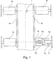
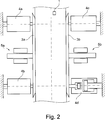
In
Auch in dieser dritten Ausführungsform der erfindungsgemäßen Führungsvorrichtung bestehen die Anstelleinrichtungen
ZITATE ENTHALTEN IN DER BESCHREIBUNG QUOTES INCLUDE IN THE DESCRIPTION
Diese Liste der vom Anmelder aufgeführten Dokumente wurde automatisiert erzeugt und ist ausschließlich zur besseren Information des Lesers aufgenommen. Die Liste ist nicht Bestandteil der deutschen Patent- bzw. Gebrauchsmusteranmeldung. Das DPMA übernimmt keinerlei Haftung für etwaige Fehler oder Auslassungen.This list of the documents listed by the applicant has been generated automatically and is included solely for the better information of the reader. The list is not part of the German patent or utility model application. The DPMA assumes no liability for any errors or omissions.
Zitierte PatentliteraturCited patent literature
- DE 1427923 A [0002] DE 1427923A [0002]
- DE 4140784 A1 [0003] DE 4140784 A1 [0003]
- DE 3423560 A1 [0005] DE 3423560 A1 [0005]
- DE 4003717 A1 [0006] DE 4003717 A1 [0006]
Claims (14)
Priority Applications (9)
| Application Number | Priority Date | Filing Date | Title |
|---|---|---|---|
| DE102009041453A DE102009041453A1 (en) | 2009-09-12 | 2009-09-12 | Guiding device for a strip rolling mill |
| RU2012114324/02A RU2507018C2 (en) | 2009-09-12 | 2010-09-09 | Strip rolling mill guide |
| JP2012528271A JP2013504431A (en) | 2009-09-12 | 2010-09-09 | Guide device for strip rolling equipment |
| US13/393,849 US20120174647A1 (en) | 2009-09-12 | 2010-09-09 | Guide device for a strip rolling installation |
| EP10754286A EP2475472A1 (en) | 2009-09-12 | 2010-09-09 | Guide device for a strip rolling mill |
| PCT/EP2010/005547 WO2011029599A1 (en) | 2009-09-12 | 2010-09-09 | Guide device for a strip rolling mill |
| KR1020127007447A KR101421978B1 (en) | 2009-09-12 | 2010-09-09 | Guide device for a strip rolling mill |
| CN2010800415457A CN102497943A (en) | 2009-09-12 | 2010-09-09 | Guide device for a strip rolling mill |
| SA110310692A SA110310692B1 (en) | 2009-09-12 | 2010-09-18 | Guide Device for a Strip Rolling Installation |
Applications Claiming Priority (1)
| Application Number | Priority Date | Filing Date | Title |
|---|---|---|---|
| DE102009041453A DE102009041453A1 (en) | 2009-09-12 | 2009-09-12 | Guiding device for a strip rolling mill |
Publications (1)
| Publication Number | Publication Date |
|---|---|
| DE102009041453A1 true DE102009041453A1 (en) | 2011-03-24 |
Family
ID=43533116
Family Applications (1)
| Application Number | Title | Priority Date | Filing Date |
|---|---|---|---|
| DE102009041453A Withdrawn DE102009041453A1 (en) | 2009-09-12 | 2009-09-12 | Guiding device for a strip rolling mill |
Country Status (9)
| Country | Link |
|---|---|
| US (1) | US20120174647A1 (en) |
| EP (1) | EP2475472A1 (en) |
| JP (1) | JP2013504431A (en) |
| KR (1) | KR101421978B1 (en) |
| CN (1) | CN102497943A (en) |
| DE (1) | DE102009041453A1 (en) |
| RU (1) | RU2507018C2 (en) |
| SA (1) | SA110310692B1 (en) |
| WO (1) | WO2011029599A1 (en) |
Families Citing this family (9)
| Publication number | Priority date | Publication date | Assignee | Title |
|---|---|---|---|---|
| DE102009014099A1 (en) * | 2008-10-28 | 2010-04-29 | Sms Siemag Aktiengesellschaft | Device and method for lateral guidance of a rolled strip transported on a roller table |
| CN102699135B (en) * | 2012-05-03 | 2015-09-09 | 本钢板材股份有限公司 | The method of adjustment coiler pinch-roll flipper guide pressure |
| CN104174700B (en) * | 2014-07-07 | 2016-01-27 | 芜湖市海联机械设备有限公司 | A kind of volume oil pressure flattens guider automatically |
| CN105197659A (en) * | 2015-08-26 | 2015-12-30 | 蚌埠市高德机械自动化科技有限公司 | Automatic cloth ironing machine of filter element plate of filter |
| CN106216434B (en) * | 2016-08-16 | 2017-11-14 | 山西太钢不锈钢股份有限公司 | Lead control method in a kind of coiling machine coil process side |
| CN106734680A (en) * | 2016-11-22 | 2017-05-31 | 上海振华重工(集团)股份有限公司 | The lateral alignment device of veneer reeling machine |
| CN108285058B (en) * | 2017-12-25 | 2020-06-19 | 安徽玄同机电科技有限公司 | Guide supporting mechanism for rewinding device of strips |
| EP3552723A1 (en) * | 2018-04-12 | 2019-10-16 | Primetals Technologies Austria GmbH | Device and method for guiding metal strips with grinding bodies having a carrier member |
| CN109624493A (en) * | 2018-12-06 | 2019-04-16 | 山东玫姿蓝家纺有限公司 | Printing device is used in a kind of processing of woollen blanket |
Citations (4)
| Publication number | Priority date | Publication date | Assignee | Title |
|---|---|---|---|---|
| DE1427923A1 (en) | 1965-06-10 | 1969-01-23 | Kloeckner Werke Ag | Guide rulers for rolling mills for the width guidance of rolled or cut strip material |
| DE3423560A1 (en) | 1984-06-27 | 1986-01-09 | SMS Schloemann-Siemag AG, 4000 Düsseldorf | POSITIONING CONTROL DEVICE FOR BEFORE THE INPUT OF WARM BROADBAND FINISHING ROLLING MILLS, CROSS-SLIDING GUIDE LINEAL OR. LEADERSHIP ROLES |
| DE4003717A1 (en) | 1990-02-08 | 1991-08-14 | Schloemann Siemag Ag | Side guidance for rolled strip material - pushing guides in controlled manner against edges of strip material |
| DE4140784A1 (en) | 1991-12-06 | 1993-06-09 | Preussag Stahl Ag, 3150 Peine, De | Method for automatic adjustment of steel belt roller conveyor guides - using friction noise sensor, bandpass filtering and signal comparison with stored data for positioning motor control. |
Family Cites Families (15)
| Publication number | Priority date | Publication date | Assignee | Title |
|---|---|---|---|---|
| NL291459A (en) * | 1962-04-16 | |||
| DE3116278A1 (en) * | 1981-04-24 | 1982-11-11 | Betriebsforschungsinstitut VDEh - Institut für angewandte Forschung GmbH, 4000 Düsseldorf | DEVICE FOR CONTROLLING THE POSITION OF THE TAPE ROLL WHILE ROLLING |
| JPS61108415A (en) * | 1984-10-31 | 1986-05-27 | Kawasaki Steel Corp | Method for controlling side guide of steel sheet in hot continuous rolling line |
| JP2767154B2 (en) * | 1990-06-07 | 1998-06-18 | 石川島播磨重工業株式会社 | Side guide width setting method and device |
| JPH0669582B2 (en) * | 1990-10-23 | 1994-09-07 | 石川島播磨重工業株式会社 | Side guide control method |
| DE69207545T2 (en) * | 1991-10-18 | 1996-08-29 | Inst Tech Precision Eng | Index feed system |
| JPH0771687B2 (en) * | 1993-04-19 | 1995-08-02 | 寿産業株式会社 | Rolling guide method for roller guides |
| JPH08174063A (en) * | 1994-12-26 | 1996-07-09 | Nippon Steel Corp | Method for controlling centering of steel strip |
| JP3033949B2 (en) * | 1997-01-17 | 2000-04-17 | 日本冶金工業株式会社 | Side guide device for rolling mill |
| JPH11123434A (en) * | 1997-10-16 | 1999-05-11 | Ishikawajima Harima Heavy Ind Co Ltd | Method and device for guiding rolled stock with its sides |
| IT1296906B1 (en) * | 1997-12-24 | 1999-08-02 | Abb Sistemi Ind Spa | DEVICE FOR ADJUSTING THE TAPE INPUT GUIDES IN A ROLLING MILL |
| KR100306703B1 (en) * | 1997-12-29 | 2001-10-19 | 이구택 | Automatic feedback position controlling side guide |
| RU2197349C2 (en) * | 1999-01-25 | 2003-01-27 | Закрытое акционерное общество "Новокраматорский машиностроительный завод" | Method for laterally guiding strip continuously moved by means of roller table, mainly from stand to coiler for further coiling it |
| JP3766576B2 (en) * | 2000-02-08 | 2006-04-12 | 新日本製鐵株式会社 | Material centering method in hot width reduction press |
| CN201046468Y (en) * | 2007-06-15 | 2008-04-16 | 中国第一重型机械集团公司 | Strong forced pushing bed |
-
2009
- 2009-09-12 DE DE102009041453A patent/DE102009041453A1/en not_active Withdrawn
-
2010
- 2010-09-09 WO PCT/EP2010/005547 patent/WO2011029599A1/en active Application Filing
- 2010-09-09 US US13/393,849 patent/US20120174647A1/en not_active Abandoned
- 2010-09-09 EP EP10754286A patent/EP2475472A1/en not_active Withdrawn
- 2010-09-09 RU RU2012114324/02A patent/RU2507018C2/en not_active IP Right Cessation
- 2010-09-09 KR KR1020127007447A patent/KR101421978B1/en not_active IP Right Cessation
- 2010-09-09 JP JP2012528271A patent/JP2013504431A/en not_active Ceased
- 2010-09-09 CN CN2010800415457A patent/CN102497943A/en active Pending
- 2010-09-18 SA SA110310692A patent/SA110310692B1/en unknown
Patent Citations (4)
| Publication number | Priority date | Publication date | Assignee | Title |
|---|---|---|---|---|
| DE1427923A1 (en) | 1965-06-10 | 1969-01-23 | Kloeckner Werke Ag | Guide rulers for rolling mills for the width guidance of rolled or cut strip material |
| DE3423560A1 (en) | 1984-06-27 | 1986-01-09 | SMS Schloemann-Siemag AG, 4000 Düsseldorf | POSITIONING CONTROL DEVICE FOR BEFORE THE INPUT OF WARM BROADBAND FINISHING ROLLING MILLS, CROSS-SLIDING GUIDE LINEAL OR. LEADERSHIP ROLES |
| DE4003717A1 (en) | 1990-02-08 | 1991-08-14 | Schloemann Siemag Ag | Side guidance for rolled strip material - pushing guides in controlled manner against edges of strip material |
| DE4140784A1 (en) | 1991-12-06 | 1993-06-09 | Preussag Stahl Ag, 3150 Peine, De | Method for automatic adjustment of steel belt roller conveyor guides - using friction noise sensor, bandpass filtering and signal comparison with stored data for positioning motor control. |
Also Published As
| Publication number | Publication date |
|---|---|
| EP2475472A1 (en) | 2012-07-18 |
| SA110310692B1 (en) | 2014-08-04 |
| WO2011029599A1 (en) | 2011-03-17 |
| RU2012114324A (en) | 2013-10-20 |
| RU2507018C2 (en) | 2014-02-20 |
| JP2013504431A (en) | 2013-02-07 |
| US20120174647A1 (en) | 2012-07-12 |
| KR20120062817A (en) | 2012-06-14 |
| CN102497943A (en) | 2012-06-13 |
| KR101421978B1 (en) | 2014-07-22 |
Similar Documents
| Publication | Publication Date | Title |
|---|---|---|
| DE102009041453A1 (en) | Guiding device for a strip rolling mill | |
| EP0121148B1 (en) | Method of making hot rolled strip with a high quality section and flatness | |
| EP3658305B1 (en) | Scaffold cooler for cooling a steel strip in a rolling stand | |
| DE102012100629A1 (en) | Method and device for connecting two ends of metallic strips | |
| DE4310547C2 (en) | Method and apparatus for preventing lateral bending of a longitudinally rolled slab | |
| DE3103530A1 (en) | METHOD FOR INTERLOCKING CALIBERS INTENDED FOR THE DIVING STICK OF A UNIVERSAL ROLLING PROCESS OF PROFILE PIECES, AND ROLLING, ROLLING DEVICES AND ROLLING MACHINES FOR CARRYING OUT THIS METHOD | |
| DE1809638A1 (en) | Device for processing sheet metal or strip material | |
| EP2741870B1 (en) | Rolling system and rolling method | |
| DE69501054T2 (en) | Device and method for producing double-rolled steel strip | |
| DE102007028710A1 (en) | Manufacturing process for pipes ...... | |
| DE1452829A1 (en) | Strip flattener | |
| EP2424687A1 (en) | Spray bar, path and method for applying a medium onto a product | |
| EP0602492B1 (en) | Cluster mill | |
| DE2048353A1 (en) | Rolling device for flattening | |
| WO2006027238A1 (en) | Method and device for milling a metal strip | |
| DE102009042694A1 (en) | Modular guide device | |
| DE1302430C2 (en) | PROCESS FOR THE CONTINUOUS MANUFACTURING OF PANELS WITH PIPES EXPANDED BY PRESSURE | |
| EP0032536A2 (en) | Device for obtaining a uniform temperature distribution in a hot steel strip during rolling | |
| DE69201395T2 (en) | Stretch roller leveler. | |
| DE19743093C1 (en) | Production of a metal strip with regions of different thickness over its width | |
| DE2630877C2 (en) | Hot rolling of metal strip | |
| DE3245031C2 (en) | ||
| DE3302333C2 (en) | ||
| DE3400608C2 (en) | Roll stand with an offset intermediate roll inserted between the work roll and the back-up roll | |
| DE102020203748A1 (en) | Upsetting device for a metal strip and method for its operation |
Legal Events
| Date | Code | Title | Description |
|---|---|---|---|
| R081 | Change of applicant/patentee |
Owner name: SMS GROUP GMBH, DE Free format text: FORMER OWNER: SMS SIEMAG AG, 40237 DUESSELDORF, DE |
|
| R082 | Change of representative |
Representative=s name: HEMMERICH & KOLLEGEN, DE |
|
| R120 | Application withdrawn or ip right abandoned |