EP1786577B1 - Method for milling a metal strip - Google Patents
Method for milling a metal strip Download PDFInfo
- Publication number
- EP1786577B1 EP1786577B1 EP05782864A EP05782864A EP1786577B1 EP 1786577 B1 EP1786577 B1 EP 1786577B1 EP 05782864 A EP05782864 A EP 05782864A EP 05782864 A EP05782864 A EP 05782864A EP 1786577 B1 EP1786577 B1 EP 1786577B1
- Authority
- EP
- European Patent Office
- Prior art keywords
- metal strip
- rolling
- strip
- roller
- differential value
- Prior art date
- Legal status (The legal status is an assumption and is not a legal conclusion. Google has not performed a legal analysis and makes no representation as to the accuracy of the status listed.)
- Revoked
Links
Images
Classifications
-
- B—PERFORMING OPERATIONS; TRANSPORTING
- B21—MECHANICAL METAL-WORKING WITHOUT ESSENTIALLY REMOVING MATERIAL; PUNCHING METAL
- B21B—ROLLING OF METAL
- B21B37/00—Control devices or methods specially adapted for metal-rolling mills or the work produced thereby
- B21B37/68—Camber or steering control for strip, sheets or plates, e.g. preventing meandering
-
- B—PERFORMING OPERATIONS; TRANSPORTING
- B21—MECHANICAL METAL-WORKING WITHOUT ESSENTIALLY REMOVING MATERIAL; PUNCHING METAL
- B21B—ROLLING OF METAL
- B21B2273/00—Path parameters
- B21B2273/04—Lateral deviation, meandering, camber of product
-
- B—PERFORMING OPERATIONS; TRANSPORTING
- B21—MECHANICAL METAL-WORKING WITHOUT ESSENTIALLY REMOVING MATERIAL; PUNCHING METAL
- B21B—ROLLING OF METAL
- B21B37/00—Control devices or methods specially adapted for metal-rolling mills or the work produced thereby
- B21B37/58—Roll-force control; Roll-gap control
-
- B—PERFORMING OPERATIONS; TRANSPORTING
- B21—MECHANICAL METAL-WORKING WITHOUT ESSENTIALLY REMOVING MATERIAL; PUNCHING METAL
- B21B—ROLLING OF METAL
- B21B39/00—Arrangements for moving, supporting, or positioning work, or controlling its movement, combined with or arranged in, or specially adapted for use in connection with, metal-rolling mills
- B21B39/14—Guiding, positioning or aligning work
- B21B39/16—Guiding, positioning or aligning work immediately before entering or after leaving the pass
Definitions
- the invention relates to a method and apparatus for reducing band saber when rolling a metal strip.
- a generic method is eg off JP-A-59118216 known.
- band sabers This refers to lateral deviations from the straightness of the strip in the longitudinal direction.
- the band saw can lead to process disturbances during the rolling process but also during later process steps, which has a negative effect on throughput and productivity.
- the causes of a non-parallel position of the rolling rolls are versatile.
- here are the different springing of the two framework stands under rolling load, an off-center position of the metal strip with respect to the roll center and different strengths of the rolling stock over the bandwidth, especially due to temperature differences of importance.
- the invention has for its object to provide a method and an apparatus that effectively reduces the formation of a tape measure when rolling metal bands. This object is achieved by the method according to claim 1.
- the essence of the invention is based on the assumption that, in particular, the geometry of the roll gap is responsible for the formation of a tieback.
- the geometry of the roll gap can be changed and thus the formation of a tieback can be reduced.
- the adjustment of the nip takes place unevenly across the width of the metal strip, i. in the longitudinal direction of the roller.
- Under rolling mill is understood according to the invention a system of at least one rolling roll and its storage.
- metal tape is understood to mean any shape of a metallic semifinished product (also in the raw state) whose length is greater than the width.
- these include slabs and slabs, flat billets and wide steel, etc. understood.
- the position of the band edge (s) can be determined by optical measuring devices.
- the position can also be determined by means of side guides, which are in constant contact with at least one band edge and follow a transverse movement of the band edge (s).
- the metal strip is guided on at least one side guide in front of the rolling stand and a side guide behind the rolling stand and measured the compressive forces in the side guides.
- the geometry of the roll gap may be changed.
- the metal strip is continuously guided on the side guide (s). This can react very quickly to changing conditions that would otherwise cause the emergence of a gangbeam. An exact control of the adjustable rolling stand is therefore possible without simultaneous thickness profile measurement.
- continuous guidance of the metal strip on the side guide (s) is understood to mean that the edges of the metal strip abut substantially on the side guide (s) at all times and thus are in constant contact with them.
- this should not be understood as lateral guides, which only come into contact with the deviations of the strip edges from their desired position and thus limit their deflection.
- a particular advantage of the two-sided arrangement of side guides is that a non-constant width of the band over its length due to the simultaneous increase or decrease of the compressive forces in the two side guides, which in turn can result in the difference to zero, not disadvantageous effect.
- the difference value can be determined, for example, by pressing the side guide (movable in the transverse direction of the metal strip) against the edge with a defined (path-dependent) contact pressure and at a movement of the band edge, the increase or decrease (difference value) of this contact force is determined.
- An influence on the measured values by a non-constant bandwidth can be avoided in this case, for example, that this is measured in the strip running direction in front of the rolling mill and is compensated by control technology.
- the target value for the control of the roller is a differential value of the determined compressive forces of zero.
- a difference value from zero means that the metal band runs perfectly straight without band saber.
- An embodiment of the invention provides for arranging at least one lateral guide with pressure force measurement on each side of the belt in front of and behind the rolling stand. By taking into account the at least four determined values for the compressive force, a bending moment can be calculated which gives a value for the control of the roller independently of the relative position of the metal strip within the guide.
- a plurality of rolling stands or one or more rolling stands and other devices of any kind between the side guide pairs may be arranged.
- any influence of an asymmetrical course in the calculation of the difference value can be taken into account, so that an adapted control of the roll (s) of the rolling stand can take place.
- the side guides may be supported to compensate for corresponding movements of the strip edges, thus compensating for the differential value of the compressive force by an asymmetric progression of the strip between the side guides.
- the side guides are designed in the form of guide rollers. These allow permanent contact with the metal strip, without causing high frictional forces and / or damage to the strip edges.
- the method according to the invention can be used particularly advantageously during hot rolling of metal strip.
- the corresponding device can be arranged in a roughing a hot rolling mill, since there is the crossflow obstruction due to the larger strip thickness and the higher temperature compared to the finishing line is sufficiently low.
- the metal strip can thus be passed as saber-free as possible to the finishing mill.
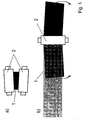
- Fig. 1 the emergence of a tieback due to a wedge-shaped roll gap is shown.
- a metal strip 1 with a wedge-shaped thickness profile is formed over the metal strip width.
- the invention now proposes to provide vertical guide rollers 3 which are arranged in pairs (one per side of the metal strip 1) in front of and behind the pair of rollers and are in constant contact with it by their transversal displacement of the band.
- the pressure force exerted by the metal strip 1 on the respective guide roller 3, is determined by a measuring device, not shown.
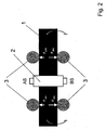
- the metal strip 1 rotates on both sides of the roll pair in mutually opposite directions (in the embodiment of FIGS Fig. 2 or 3 towards the operator side). This increases the force which is measured by the two operator-side guide rollers 3. To the same extent, the forces measured by the guide rollers 3 of the drive side AS decrease.
- the geometry of the roll gap is corrected accordingly, so that a band saw, which arises due to non-parallel alignment of the rollers 2, is effectively reduced.
- the formation of a belt and other influences by actively influencing the roll gap geometry can be influenced or reduced by the inventive device and the corresponding method.
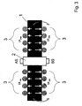
- Fig. 3 an embodiment of the device according to the invention is shown, which is functional to that of the Fig. 2 is identical, but has a plurality of guide rollers with force measuring devices, which are arranged uniformly on both sides of the belt and in front of and behind the pair of rolling rollers. Due to the large number of measuring points, the accuracy of the measurement and thus the influence of the tape measure can be significantly increased.
- an improved guidance of the metal strip can be achieved by increasing the number of guide rollers.
Abstract
Description
Die Erfindung betrifft ein Verfahren sowie eine Vorrichtung zur Verringerung von Bandsäbeln beim Walzen eines Metallbands. Ein gattungsgemäßes Verfahren ist z.B. aus
Eines der bei der Metallbanderzeugung, insbesondere bei der Warmbanderzeugung ungelösten Probleme ist das Auftreten von sogenannten Bandsäbeln. Damit werden seitliche Abweichungen von der Geradheit des Bandes in Längsrichtung bezeichnet. Der Bandsäbel kann zu Prozeßstörungen während des Walzvorganges aber auch während späterer Prozeßschritte führen, was sich negativ auf den Durchsatz sowie auf die Produktivität auswirkt.One of the problems unresolved in metal strip production, particularly in hot strip production, is the appearance of so-called band sabers. This refers to lateral deviations from the straightness of the strip in the longitudinal direction. The band saw can lead to process disturbances during the rolling process but also during later process steps, which has a negative effect on throughput and productivity.
Um den negativen Einfluß von Bandsäbeln auf nachfolgende Verarbeitungsprozesse zu reduzieren ist es bekannt, das Metallband durch Seitenführungen, die beidseitig vor und/oder hinter einem Walzgerüst angeordnet sind, zwangszuführen. Dadurch kann verhindert werden, daß das Metallband in nicht zulässigem Maße seitlich verläuft.In order to reduce the negative influence of band sabers on subsequent processing processes, it is known to force the metal strip through side guides which are arranged on both sides in front of and / or behind a roll stand. As a result, it can be prevented that the metal strip extends laterally to an unacceptable extent.
Durch die Zwangsführung des Metallbandes wird zwar der Bandsäbel und damit die negativen Auswirkungen, die dieser auf nachfolgende Prozesse haben könnte, verhindert. Die Ursachen, die zum Auftreten von Bandsäbeln führen, werden dadurch jedoch nicht behoben, so daß das Problem nicht in seinem Ursprung beseitigt wird.Due to the positive guidance of the metal strip, the band saw and thus the negative effects this could have on subsequent processes are prevented. The causes leading to the appearance of band sabers However, this does not solve the problem, so that the problem is not eliminated in its origin.
Untersuchungen haben gezeigt, daß insbesondere eine nicht-parallele Ausrichtung der Arbeitswalzen und der Walzkraft zur Ausbildung von Bandsäbeln führt. Das Walzen des Bands in einem nicht-parallelen, also keiligen Walzspalt führt zu einem ungleichförmigen Dickenprofil des Bands und gleichzeitig aufgrund der plastischen Verformung des Bands durch die Walzrolle zu einer unterschiedlichen Ausbildung der Bandlänge über der Bandbreite. Die unterschiedlichen Bandlängen führen wiederum zu einer Rotation des Bandes auf dem Rollgang und zu einem Bandsäbel.Investigations have shown that in particular a non-parallel alignment of the work rolls and the rolling force leads to the formation of band sabots. The rolling of the strip in a non-parallel, that is wedged, nip results in a nonuniform thickness profile of the strip and, at the same time, due to the plastic deformation of the strip by the roller, to a different formation of the strip length over the strip width. The different tape lengths in turn lead to a rotation of the tape on the roller table and a band saber.
Die Ursachen für eine nicht-parallele Lage der Walzrollen sind vielseitig. Unter anderem sind hierbei die unterschiedliche Auffederung der beiden Gerüstständer unter Walzlast, eine außermittige Lage des Metallbands in Bezug auf die Walzenmitte und unterschiedliche Festigkeiten des Walzguts über der Bandbreite, insbesondere bedingt durch Temperaturunterschiede von Bedeutung.The causes of a non-parallel position of the rolling rolls are versatile. Among other things, here are the different springing of the two framework stands under rolling load, an off-center position of the metal strip with respect to the roll center and different strengths of the rolling stock over the bandwidth, especially due to temperature differences of importance.
Der Erfindung liegt die Aufgabe zugrunde, ein Verfahren sowie eine Vorrichtung zu schaffen, die die Entstehung eines Bandsäbels beim Walzen von Metallbändern wirksam verringert. Diese Aufgabe wird durch das Verfahren nach Anspruch 1 gelöst.The invention has for its object to provide a method and an apparatus that effectively reduces the formation of a tape measure when rolling metal bands. This object is achieved by the method according to
Der Kern der Erfindung beruht auf der Annahme, daß insbesondere die Geometrie des Walzspalts für die Entstehung eines Bandsäbels verantwortlich ist. Durch eine entsprechende Ansteuerung der Walze innerhalb eines Walzgerüsts kann die Geometrie des Walzspalts verändert und damit die Ausbildung eines Bandsäbels verringert werden.The essence of the invention is based on the assumption that, in particular, the geometry of the roll gap is responsible for the formation of a tieback. By an appropriate control of the roller within a roll stand, the geometry of the roll gap can be changed and thus the formation of a tieback can be reduced.
Dazu ist vorgesehen, die Position von mindestens einer Kante des Metallbands und/oder eine Druckkraft, die diese Kante(n) auf ein angrenzendes Bauteil ausübt, vor und hinter einem Walzgerüst zu messen, um anhand eines Wertes für das Biegemoment, das sich aus dem Differenzwert der Messergebnisse der Seitenführung vor dem Walzgerüst und dem Differenzwert der Seitenführung hinter dem Walzgerüst ergibt, die Geometrie des Walzspalts zu verändern, beispielsweise indem mindestens eine Walze des Walzgerüsts angesteuert und verstellt wird.For this purpose, it is provided to measure the position of at least one edge of the metal strip and / or a compressive force that exerts this edge (s) on an adjacent component, in front of and behind a roll stand, in order to a value for the bending moment, which results from the difference value of the measurement results of the side guide in front of the roll stand and the difference value of the side guide behind the roll stand, to change the geometry of the roll gap, for example by at least one roller of the roll stand is controlled and adjusted.
Vorteilhafterweise erfolgt die Verstellung des Walzspalts ungleichförmig über der Breite des Metallbands, d.h. in Längsrichtung der Walze.Advantageously, the adjustment of the nip takes place unevenly across the width of the metal strip, i. in the longitudinal direction of the roller.
Auf diese Weise kann eine unbeabsichtigte nicht-parallele Ausrichtung der Arbeitswalze(n), wie sie aus den oben genannten Gründen entstehen kann, durch aktive Ansteuerung ausgeglichen werden.In this way, an unintentional non-parallel alignment of the work roll (s), as may arise for the reasons mentioned above, can be compensated by active control.
Unter Walzgerüst wird erfindungsgemäß ein System aus mindestens einer Walzrolle und dessen Lagerung verstanden.Under rolling mill is understood according to the invention a system of at least one rolling roll and its storage.
Unter Metallband soll erfindungsgemäß jede Form eines metallischen Halbzeugs (auch im Rohzustand) verstanden werden, dessen Länge größer als die Breite ist. Insbesondere werden darunter Brammen und Vorbrammen, Flachknüppel und Breitstahl, etc. verstanden.According to the invention, metal tape is understood to mean any shape of a metallic semifinished product (also in the raw state) whose length is greater than the width. In particular, these include slabs and slabs, flat billets and wide steel, etc. understood.
Beispielsweise kann die Position der Bandkante(n) durch optische Meßgeräte bestimmt werden. Alternativ kann die Position auch anhand von Seitenführungen bestimmt werden, die im ständigen Kontakt mit mindestens einer Bandkante stehen und einer Querbewegung der Bandkante(n) folgen.For example, the position of the band edge (s) can be determined by optical measuring devices. Alternatively, the position can also be determined by means of side guides, which are in constant contact with at least one band edge and follow a transverse movement of the band edge (s).
In einer Alternative der vorliegenden Erfindung wird das Metallband an mindestens einer Seitenführung vor dem Walzgerüst und einer Seitenführung hinter dem Walzgerüst geführt und die Druckkräfte in den Seitenführungen gemessen. Somit kann beim Auftreten eines Differenzwerts der Druckkräfte in den Seitenführungen die Geometrie des Walzspalts verändert werden.In an alternative of the present invention, the metal strip is guided on at least one side guide in front of the rolling stand and a side guide behind the rolling stand and measured the compressive forces in the side guides. Thus, upon the occurrence of a differential value of the compressive forces in the side guides, the geometry of the roll gap may be changed.
In einer vorteilhaften Weiterbildung wird das Metallband kontinuierlich an der/den Seitenführung(en) geführt. Dadurch kann sehr schnell auf sich ändernde Bedingungen reagiert werden, die ansonsten die Entstehung eines Bandsäbels nach sich ziehen würden. Eine exakte Steuerung des verstellbaren Walzgerüsts ist folglich auch ohne gleichzeitige Dickenprofilmessung möglich.In an advantageous development, the metal strip is continuously guided on the side guide (s). This can react very quickly to changing conditions that would otherwise cause the emergence of a gangbeam. An exact control of the adjustable rolling stand is therefore possible without simultaneous thickness profile measurement.
Unter "kontinuierlicher Führung" des Metallbands an der/den Seitenführung(en) wird im Sinne der Erfindung verstanden, daß die Kanten des Metallbands im wesentlichen jederzeit an der/den Seitenführung(en) anliegen und somit in ständigem Kontakt mit diesen stehen. Insbesondere sollen darunter nicht Seitenführungen verstanden werden, die erst beim Abweichen der Bandkanten aus ihrer Sollage mit diesen in Kontakt kommen und somit deren Ablenkung begrenzen.In the sense of the invention, "continuous guidance" of the metal strip on the side guide (s) is understood to mean that the edges of the metal strip abut substantially on the side guide (s) at all times and thus are in constant contact with them. In particular, this should not be understood as lateral guides, which only come into contact with the deviations of the strip edges from their desired position and thus limit their deflection.
Vorteilhaft kann es sein, das Metallband vor und/oder hinter dem Walzgerüst beidseitig an mindestens einer Seitenführung zu führen. Der Differenzwert für die Druckkräfte ergibt sich dann auf einfache Weise aus den zwei gemessenen Werten.It may be advantageous to guide the metal strip in front of and / or behind the roll stand on both sides on at least one side guide. The difference value for the pressure forces then results in a simple way from the two measured values.
Ein besonderer Vorteil der beidseitigen Anordnung von Seitenführungen liegt darin, daß sich eine nicht-konstante Breite des Bands über dessen Länge aufgrund der gleichzeitigen Erhöhung bzw. Verringerung der Druckkräfte in den beiden Seitenführungen, die sich in der Differenz wiederum zu Null ergeben kann, nicht nachteilig auswirkt.A particular advantage of the two-sided arrangement of side guides is that a non-constant width of the band over its length due to the simultaneous increase or decrease of the compressive forces in the two side guides, which in turn can result in the difference to zero, not disadvantageous effect.
Bei einer alternativen Ausführungsform mit nur einer einseitigen Führung des Metallbands vor und/oder hinter dem Walzgerüst kann der Differenzwert beispielsweise dadurch ermittelt werden, daß die (in Querrichtung des Metallbands bewegliche) Seitenführung mit einer definierten (wegabhängigen) Anpreßkraft auf die Kante gedrückt wird und bei einer Bewegung der Bandkante die Zu- oder Abnahme (Differenzwert) dieser Anpreßkraft ermittelt wird.In an alternative embodiment with only one-sided guidance of the metal strip in front of and / or behind the roll stand, the difference value can be determined, for example, by pressing the side guide (movable in the transverse direction of the metal strip) against the edge with a defined (path-dependent) contact pressure and at a movement of the band edge, the increase or decrease (difference value) of this contact force is determined.
Ein Einfluß auf die Meßwerte durch eine nicht-konstante Bandbreite kann in diesem Fall beispielsweise dadurch vermieden werden, daß diese in Bandlaufrichtung vor dem Walzgerüst gemessen wird und regelungstechnisch ausgeglichen wird.An influence on the measured values by a non-constant bandwidth can be avoided in this case, for example, that this is measured in the strip running direction in front of the rolling mill and is compensated by control technology.
In einer vorteilhaften Weiterbildung gilt als Zielwert für die Ansteuerung der Walze ein Differenzwert der ermittelten Druckkräfte von Null. Ein Differenzwert von Null bedeutet demnach, daß das Metallband vollkommen gerade ohne Bandsäbel verläuft. Hierbei können Druckkraftunterschiede in den Seitenführungen auf beiden Seiten des Metallbands, die durch eine asymmetrische Position oder einen Schräglauf des Metallbands zwischen den Führungen entstehen, ebenfalls mathematisch oder regelungstechnisch herausgefiltert werden.In an advantageous development, the target value for the control of the roller is a differential value of the determined compressive forces of zero. A difference value from zero means that the metal band runs perfectly straight without band saber. This pressure force differences in the side guides on both sides of the metal strip, which arise from an asymmetric position or a skew of the metal strip between the guides, also be mathematically or control technology filtered out.
Eine Ausführungsform der Erfindung sieht vor, vor und hinter dem Walzgerüst mindestens jeweils eine Seitenführung mit Druckkraftmessung auf jeder Seite des Bandes anzuordnen. Durch ein Inbezugsetzen der mindestens vier ermittelten Werte für die Druckkraft kann ein Biegemoment errechnet werden, das unabhängig von der relativen Position des Metallbands innerhalb der Führung einen Wert für die Ansteuerung der Walze ergibt.An embodiment of the invention provides for arranging at least one lateral guide with pressure force measurement on each side of the belt in front of and behind the rolling stand. By taking into account the at least four determined values for the compressive force, a bending moment can be calculated which gives a value for the control of the roller independently of the relative position of the metal strip within the guide.
Bei dieser Ausführungsform können selbstverständlich auch mehrere Walzgerüste oder ein oder mehrere Walzgerüste und weitere Vorrichtungen beliebiger Art zwischen den Seitenführungspaaren angeordnet sein.In this embodiment, of course, a plurality of rolling stands or one or more rolling stands and other devices of any kind between the side guide pairs may be arranged.
In einer alternativen Ausführungsform kann jedoch vorgesehen sein, lediglich vor oder hinter dem Walzgerüst mindestens zwei Seitenführungen vorzusehen, die einen entsprechenden Differenzwert für die Druckkraft bilden.In an alternative embodiment, however, it may be provided to provide only at least two side guides in front of or behind the roll stand, which form a corresponding differential value for the pressure force.
Durch eine Bestimmung der Position des Bandes in Relation zu der oder den Walzen des Walzengerüsts kann ein eventueller Einfluß eines asymmetrischen Verlaufs bei der Berechnung des Differenzwerts berücksichtigt werden, so daß eine angepaßte Ansteuerung der Walze(n) des Walzgerüsts erfolgen kann.By determining the position of the belt in relation to the roller (s) of the rolling stand, any influence of an asymmetrical course in the calculation of the difference value can be taken into account, so that an adapted control of the roll (s) of the rolling stand can take place.
Alternativ können die Seitenführungen so gelagert werden, daß sie entsprechende Bewegungen der Bandkanten ausgleichen und somit eine Beeinflussung des Differenzwerts für die Druckkraft durch einen asymmetrischem Verlauf des Bands zwischen den Seitenführungen ausgleichen.Alternatively, the side guides may be supported to compensate for corresponding movements of the strip edges, thus compensating for the differential value of the compressive force by an asymmetric progression of the strip between the side guides.
In einer vorteilhaften Ausführungsform sind die Seitenführungen in Form von Führungsrollen ausgebildet. Diese ermöglichen einen permanenten Kontakt mit dem Metallband, ohne daß hohe Reibungskräfte und/oder Beschädigungen der Bandkanten entstehen.In an advantageous embodiment, the side guides are designed in the form of guide rollers. These allow permanent contact with the metal strip, without causing high frictional forces and / or damage to the strip edges.
Das erfindungsgemäße Verfahren kann besonders vorteilhaft beim Warmwalzen von Metallband eingesetzt werden. Insbesondere kann die entsprechende Vorrichtung in einer Vorstraße einer Warmwalzstraße angeordnet werden, da dort die Querflußbehinderung aufgrund der größeren Banddicke sowie der höheren Temperatur im Vergleich zur Fertigstraße ausreichend gering ist. Das Metallband kann somit möglichst säbelfrei an die Fertigstraße übergeben werden.The method according to the invention can be used particularly advantageously during hot rolling of metal strip. In particular, the corresponding device can be arranged in a roughing a hot rolling mill, since there is the crossflow obstruction due to the larger strip thickness and the higher temperature compared to the finishing line is sufficiently low. The metal strip can thus be passed as saber-free as possible to the finishing mill.
Die Erfindung wird nachfolgend anhand eines Ausführungsbeispiels näher erläutert. In den Zeichnungen zeigt:
- Fig. 1
- die Entstehung eines Bandsäbels aufgrund einer nicht-parallelen Ausrichtung eines Walzenpaares in einem Querschnitt (a) sowie einer Draufsicht (b);
- Fig. 2
- eine Ausführungsform einer erfindungsgemäßen Vorrichtung zum Walzen von Metallbändern in einer Draufsicht und
- Fig. 3
- eine alternative Ausführungsform einer erfindungsgemäßen Vorrichtung zum Walzen von Metallbändern.
- Fig. 1
- the emergence of a tape bundle due to a non-parallel alignment of a pair of rollers in a cross-section (a) and a plan view (b);
- Fig. 2
- an embodiment of a device according to the invention for rolling metal bands in a plan view and
- Fig. 3
- an alternative embodiment of an apparatus for rolling metal bands according to the invention.
In
Durch den nicht-parallelen Walzspalt des Walzenpaares entsteht ein Metallband 1 mit einem keilförmigen Dickenprofil über der Metallbandbreite.Due to the non-parallel roller gap of the roller pair, a
Dies führt aufgrund der plastischen Verformung gleichzeitig zu einer ungleichförmigen Längenausdehnung des Metallbands 1 über der Breite. Die unterschiedlichen Längenausdehnungen wiederum begründen eine Geradheitsabweichung des Metallbands 1 in Längsrichtung, so daß das Metallband 1 auf beiden Seiten der Walzen 2 des Walzenpaares aus dem ideal geraden Verlauf in zueinander entgegengesetzter Richtung heraus rotiert.Due to the plastic deformation, this simultaneously leads to a non-uniform longitudinal expansion of the
In einer Ausführungsform sieht die Erfindung nun vor, vertikale Führungsrollen 3 vorzusehen, die paarweise (jeweils eine pro Seite des Metallbands 1) vor und hinter dem Walzenpaar angeordnet sind und durch ihre Verschiebbarkeit in Querrichtung des Bands im ständigen Kontakt mit diesem stehen. Die Druckkraft, die das Metallband 1 auf die jeweilige Führungsrolle 3 ausübt, wird über eine nicht dargestellte Meßvorrichtung bestimmt.In one embodiment, the invention now proposes to provide
Bei einem ideal geraden Verlauf des Metallbands 1 ohne Bandsäbel ergibt die Summe der Kräfte auf der Bedienerseite BS den gleichen Wert wie die Summe der Kräfte auf der Antriebsseite AS.In the case of an ideally straight course of the
Sobald aufgrund eines nicht-parallelen Walzspalts ein Bandsäbel entsteht, rotiert das Metallband 1 auf beiden Seiten des Walzenpaares in zueinander entgegengesetzter Richtung (im Ausführungsbeispiel der
Anhand dieser Kraftdifferenz zwischen Bedienerseite BS und Antriebsseite AS kann ein Rückschluß auf die Größe des Bandsäbels gezogen werden. Der somit erhaltene Differenzwert wird zur Ansteuerung der zueinander verstellbaren Walzen 2 verwendet.Based on this force difference between the operator side BS and drive side AS, a conclusion can be drawn on the size of the tether. The difference value thus obtained is used to control the mutually
Durch die Ansteuerung der verstellbaren Walzen 2 wird die Geometrie des Walzspalts entsprechend korrigiert, so daß ein Bandsäbel, der aufgrund einer nicht-parallelen Ausrichtung der Walzen 2 entsteht, wirksam verringert wird.By controlling the
Gleichsam kann durch die erfindungsgemäße Vorrichtung sowie das entsprechende Verfahren die Entstehung eines Bandsäbels und anderer Einflüsse durch aktive Beeinflussung der Walzspaltgeometrie beeinflußt bzw. verringert werden.Likewise, the formation of a belt and other influences by actively influencing the roll gap geometry can be influenced or reduced by the inventive device and the corresponding method.
In
Ferner kann durch eine Erhöhung der Anzahl der Führungsrollen eine verbesserte Führung des Metallbands erreicht werden.Furthermore, an improved guidance of the metal strip can be achieved by increasing the number of guide rollers.
Claims (7)
- Method for the reduction of strip sharp edges when rolling a metal strip (1) with the following steps:- guiding of the metal strip (1) at at least one lateral guide (3) before and after a rolling stand; and- measuring of the pressure forces in the lateral guides (3) and/or the position of the lateral guides in order to determine a differential value and, in this measuring of the pressure force on an adjacent component of at least one edge of the metal strip before and after a rolling stand, characterised by:- the adaptation of the rolling gap geometry for the reduction of the strip sharp edge on the basis of a value for the bending moment, which derives from the differential value of the measurement results from the lateral guide(s) (3) before the rolling stand and the differential value of the lateral guide(s) (3) after the rolling stand.
- Method according to Claim 1, characterised by an irregular setting of the rolling gap in the longitudinal direction of the roller (2).
- Method according to Claim 1 or 2, characterised by the continuous guidance of the metal strip (1) at the lateral guides (3).
- Method according to any one of Claims 1 to 3, characterised by a guidance of the metal strip (1) on both sides, before and/or after the rolling stand.
- Method according to any one of Claims 1 to 4, characterised by an adaptation of the rolling gap geometry, with a target value of zero for the differential value of the pressure forces.
- Method according to any one of Claims 1 to 5, characterised by the actuation of the roller (2) on the basis of a differential value of the lateral guides (3) before or after the rolling stand, in conjunction with a determination of the course of the strip relative to the roller (2).
- Method according to any one of the preceding claims, characterised by the hot rolling of the metal strip (1).
Applications Claiming Priority (2)
| Application Number | Priority Date | Filing Date | Title |
|---|---|---|---|
| DE102004043790A DE102004043790A1 (en) | 2004-09-08 | 2004-09-08 | Method and device for rolling a metal strip |
| PCT/EP2005/009627 WO2006027238A1 (en) | 2004-09-08 | 2005-09-08 | Method and device for milling a metal strip |
Publications (2)
| Publication Number | Publication Date |
|---|---|
| EP1786577A1 EP1786577A1 (en) | 2007-05-23 |
| EP1786577B1 true EP1786577B1 (en) | 2009-11-04 |
Family
ID=35427588
Family Applications (1)
| Application Number | Title | Priority Date | Filing Date |
|---|---|---|---|
| EP05782864A Revoked EP1786577B1 (en) | 2004-09-08 | 2005-09-08 | Method for milling a metal strip |
Country Status (4)
| Country | Link |
|---|---|
| EP (1) | EP1786577B1 (en) |
| AT (1) | ATE447447T1 (en) |
| DE (2) | DE102004043790A1 (en) |
| WO (1) | WO2006027238A1 (en) |
Families Citing this family (5)
| Publication number | Priority date | Publication date | Assignee | Title |
|---|---|---|---|---|
| DE102006059709A1 (en) * | 2006-12-18 | 2008-06-19 | Siemens Ag | Rolling process for a strip |
| DE102007001539A1 (en) | 2007-01-10 | 2008-07-17 | Siemens Ag | Control method for a roll stand for rolling a strip |
| DE102008007247A1 (en) | 2007-09-13 | 2009-03-19 | Siemens Aktiengesellschaft | Operating method for a rolling mill with curvature detection |
| WO2018095717A1 (en) | 2016-11-24 | 2018-05-31 | Primetals Technologies Germany Gmbh | Strip position control with force-limited adjustment of lateral guides for the metal strip and correction of the roll adjustment |
| EP3599038A1 (en) * | 2018-07-25 | 2020-01-29 | Primetals Technologies Austria GmbH | Method and device for determining the lateral contour of a running metal strip |
Family Cites Families (6)
| Publication number | Priority date | Publication date | Assignee | Title |
|---|---|---|---|---|
| DE3116278A1 (en) * | 1981-04-24 | 1982-11-11 | Betriebsforschungsinstitut VDEh - Institut für angewandte Forschung GmbH, 4000 Düsseldorf | DEVICE FOR CONTROLLING THE POSITION OF THE TAPE ROLL WHILE ROLLING |
| JPS5945011A (en) * | 1982-09-07 | 1984-03-13 | Ishikawajima Harima Heavy Ind Co Ltd | Method and device for preventing rolling material from meandering |
| JPS59118216A (en) * | 1982-12-25 | 1984-07-07 | Sumitomo Metal Ind Ltd | Method for controlling sheet camber |
| JPS59127915A (en) * | 1983-01-07 | 1984-07-23 | Sumitomo Metal Ind Ltd | Controlling method of plate camber |
| JPS59189011A (en) * | 1983-04-12 | 1984-10-26 | Ishikawajima Harima Heavy Ind Co Ltd | Method and device for controlling meandering and lateral deviation of rolling material |
| JPS59191510A (en) * | 1983-04-13 | 1984-10-30 | Ishikawajima Harima Heavy Ind Co Ltd | Method and device for controlling meander of rolling material |
-
2004
- 2004-09-08 DE DE102004043790A patent/DE102004043790A1/en not_active Withdrawn
-
2005
- 2005-09-08 WO PCT/EP2005/009627 patent/WO2006027238A1/en active Application Filing
- 2005-09-08 EP EP05782864A patent/EP1786577B1/en not_active Revoked
- 2005-09-08 AT AT05782864T patent/ATE447447T1/en not_active IP Right Cessation
- 2005-09-08 DE DE502005008450T patent/DE502005008450D1/en active Active
Also Published As
| Publication number | Publication date |
|---|---|
| WO2006027238A1 (en) | 2006-03-16 |
| ATE447447T1 (en) | 2009-11-15 |
| EP1786577A1 (en) | 2007-05-23 |
| DE102004043790A1 (en) | 2006-03-09 |
| DE502005008450D1 (en) | 2009-12-17 |
Similar Documents
| Publication | Publication Date | Title |
|---|---|---|
| EP1781429B1 (en) | Method for straightening a metal strip and straightening machine | |
| EP2477764B1 (en) | Method and device for continuously stretch-bend-leveling metal strips | |
| EP1896200B1 (en) | Process and device for intentionally influencing the geometry of roughed-down strips in a roughing-down stand | |
| EP1955786B1 (en) | Method for levelling metal strips | |
| DE3600144A1 (en) | ARRANGEMENT FOR REMOVING TIN, FROM HOT ROLLED STEEL TAPES | |
| EP1786577B1 (en) | Method for milling a metal strip | |
| DE4310547C2 (en) | Method and apparatus for preventing lateral bending of a longitudinally rolled slab | |
| EP3544751B1 (en) | Strip position control with force-limited placement of lateral guiding devices on the metal strip | |
| AT509831B1 (en) | METHOD AND DEVICE FOR MINIMIZING THE STRAP TRAIN OF A ROLL | |
| DE3622926C2 (en) | Continuous multi-stage rolling mill | |
| DE2856525A1 (en) | METHOD AND DEVICE FOR PROCESSING WITH DIE ROLLERS OR PRINTING ROLLS | |
| DE102005059692A1 (en) | Process for continuous casting of thin metal strips and continuous casting plant | |
| EP3253505B1 (en) | Method and apparatus for embossing rolling metal strip | |
| EP0976466A2 (en) | Method and device for the manufacture of a tube from strip material | |
| EP2741870B1 (en) | Rolling system and rolling method | |
| DE10037867A1 (en) | Flexible rolling process, for metal strip, involves work roll bending line control during or immediately after each roll gap adjustment to obtain flat strip | |
| DE19962754A1 (en) | Process for flexibly rolling a metal strip comprises carrying out a compensation of the temperature influence effecting the metal strip during rolling to avoid deviations | |
| EP3826781B1 (en) | Method and device for determining the lateral contour of a running metal strip | |
| DE3245031C2 (en) | ||
| DE19903926A1 (en) | Process and plant for forming metal strips | |
| AT510957B1 (en) | METHOD AND DEVICE FOR PRODUCING A METALLIC TAPE | |
| DE202019106037U1 (en) | System for the production of profiles from a metal strip | |
| AT250766B (en) | Method and device for stretching a metal strip | |
| EP3456426B1 (en) | Cooling of an inclined flat product which is to be rolled | |
| DE19828575B4 (en) | Metal strip forming method using hot strip mill |
Legal Events
| Date | Code | Title | Description |
|---|---|---|---|
| PUAI | Public reference made under article 153(3) epc to a published international application that has entered the european phase |
Free format text: ORIGINAL CODE: 0009012 |
|
| 17P | Request for examination filed |
Effective date: 20070206 |
|
| AK | Designated contracting states |
Kind code of ref document: A1 Designated state(s): AT BE BG CH CY CZ DE DK EE ES FI FR GB GR HU IE IS IT LI LT LU LV MC NL PL PT RO SE SI SK TR |
|
| 17Q | First examination report despatched |
Effective date: 20070608 |
|
| DAX | Request for extension of the european patent (deleted) | ||
| GRAP | Despatch of communication of intention to grant a patent |
Free format text: ORIGINAL CODE: EPIDOSNIGR1 |
|
| RTI1 | Title (correction) |
Free format text: METHOD FOR MILLING A METAL STRIP |
|
| GRAS | Grant fee paid |
Free format text: ORIGINAL CODE: EPIDOSNIGR3 |
|
| RAP1 | Party data changed (applicant data changed or rights of an application transferred) |
Owner name: VDEH-BETRIEBSFORSCHUNGSINSTITUT GMBH |
|
| GRAA | (expected) grant |
Free format text: ORIGINAL CODE: 0009210 |
|
| AK | Designated contracting states |
Kind code of ref document: B1 Designated state(s): AT BE BG CH CY CZ DE DK EE ES FI FR GB GR HU IE IS IT LI LT LU LV MC NL PL PT RO SE SI SK TR |
|
| REG | Reference to a national code |
Ref country code: GB Ref legal event code: FG4D Free format text: NOT ENGLISH |
|
| REG | Reference to a national code |
Ref country code: CH Ref legal event code: EP |
|
| REG | Reference to a national code |
Ref country code: IE Ref legal event code: FG4D |
|
| REF | Corresponds to: |
Ref document number: 502005008450 Country of ref document: DE Date of ref document: 20091217 Kind code of ref document: P |
|
| NLV1 | Nl: lapsed or annulled due to failure to fulfill the requirements of art. 29p and 29m of the patents act | ||
| LTIE | Lt: invalidation of european patent or patent extension |
Effective date: 20091104 |
|
| PG25 | Lapsed in a contracting state [announced via postgrant information from national office to epo] |
Ref country code: IS Free format text: LAPSE BECAUSE OF FAILURE TO SUBMIT A TRANSLATION OF THE DESCRIPTION OR TO PAY THE FEE WITHIN THE PRESCRIBED TIME-LIMIT Effective date: 20100304 Ref country code: SE Free format text: LAPSE BECAUSE OF FAILURE TO SUBMIT A TRANSLATION OF THE DESCRIPTION OR TO PAY THE FEE WITHIN THE PRESCRIBED TIME-LIMIT Effective date: 20091104 Ref country code: PT Free format text: LAPSE BECAUSE OF FAILURE TO SUBMIT A TRANSLATION OF THE DESCRIPTION OR TO PAY THE FEE WITHIN THE PRESCRIBED TIME-LIMIT Effective date: 20100304 Ref country code: LT Free format text: LAPSE BECAUSE OF FAILURE TO SUBMIT A TRANSLATION OF THE DESCRIPTION OR TO PAY THE FEE WITHIN THE PRESCRIBED TIME-LIMIT Effective date: 20091104 Ref country code: FI Free format text: LAPSE BECAUSE OF FAILURE TO SUBMIT A TRANSLATION OF THE DESCRIPTION OR TO PAY THE FEE WITHIN THE PRESCRIBED TIME-LIMIT Effective date: 20091104 Ref country code: ES Free format text: LAPSE BECAUSE OF FAILURE TO SUBMIT A TRANSLATION OF THE DESCRIPTION OR TO PAY THE FEE WITHIN THE PRESCRIBED TIME-LIMIT Effective date: 20100215 |
|
| REG | Reference to a national code |
Ref country code: IE Ref legal event code: FD4D |
|
| PG25 | Lapsed in a contracting state [announced via postgrant information from national office to epo] |
Ref country code: CY Free format text: LAPSE BECAUSE OF FAILURE TO SUBMIT A TRANSLATION OF THE DESCRIPTION OR TO PAY THE FEE WITHIN THE PRESCRIBED TIME-LIMIT Effective date: 20091104 Ref country code: SI Free format text: LAPSE BECAUSE OF FAILURE TO SUBMIT A TRANSLATION OF THE DESCRIPTION OR TO PAY THE FEE WITHIN THE PRESCRIBED TIME-LIMIT Effective date: 20091104 Ref country code: PL Free format text: LAPSE BECAUSE OF FAILURE TO SUBMIT A TRANSLATION OF THE DESCRIPTION OR TO PAY THE FEE WITHIN THE PRESCRIBED TIME-LIMIT Effective date: 20091104 Ref country code: LV Free format text: LAPSE BECAUSE OF FAILURE TO SUBMIT A TRANSLATION OF THE DESCRIPTION OR TO PAY THE FEE WITHIN THE PRESCRIBED TIME-LIMIT Effective date: 20091104 |
|
| PG25 | Lapsed in a contracting state [announced via postgrant information from national office to epo] |
Ref country code: IE Free format text: LAPSE BECAUSE OF FAILURE TO SUBMIT A TRANSLATION OF THE DESCRIPTION OR TO PAY THE FEE WITHIN THE PRESCRIBED TIME-LIMIT Effective date: 20091104 Ref country code: DK Free format text: LAPSE BECAUSE OF FAILURE TO SUBMIT A TRANSLATION OF THE DESCRIPTION OR TO PAY THE FEE WITHIN THE PRESCRIBED TIME-LIMIT Effective date: 20091104 Ref country code: BG Free format text: LAPSE BECAUSE OF FAILURE TO SUBMIT A TRANSLATION OF THE DESCRIPTION OR TO PAY THE FEE WITHIN THE PRESCRIBED TIME-LIMIT Effective date: 20100204 Ref country code: EE Free format text: LAPSE BECAUSE OF FAILURE TO SUBMIT A TRANSLATION OF THE DESCRIPTION OR TO PAY THE FEE WITHIN THE PRESCRIBED TIME-LIMIT Effective date: 20091104 Ref country code: RO Free format text: LAPSE BECAUSE OF FAILURE TO SUBMIT A TRANSLATION OF THE DESCRIPTION OR TO PAY THE FEE WITHIN THE PRESCRIBED TIME-LIMIT Effective date: 20091104 |
|
| PLBI | Opposition filed |
Free format text: ORIGINAL CODE: 0009260 |
|
| PG25 | Lapsed in a contracting state [announced via postgrant information from national office to epo] |
Ref country code: CZ Free format text: LAPSE BECAUSE OF FAILURE TO SUBMIT A TRANSLATION OF THE DESCRIPTION OR TO PAY THE FEE WITHIN THE PRESCRIBED TIME-LIMIT Effective date: 20091104 Ref country code: SK Free format text: LAPSE BECAUSE OF FAILURE TO SUBMIT A TRANSLATION OF THE DESCRIPTION OR TO PAY THE FEE WITHIN THE PRESCRIBED TIME-LIMIT Effective date: 20091104 |
|
| 26 | Opposition filed |
Opponent name: SIEMENS AKTIENGESELLSCHAFT Effective date: 20100722 |
|
| PLAX | Notice of opposition and request to file observation + time limit sent |
Free format text: ORIGINAL CODE: EPIDOSNOBS2 |
|
| PG25 | Lapsed in a contracting state [announced via postgrant information from national office to epo] |
Ref country code: GR Free format text: LAPSE BECAUSE OF FAILURE TO SUBMIT A TRANSLATION OF THE DESCRIPTION OR TO PAY THE FEE WITHIN THE PRESCRIBED TIME-LIMIT Effective date: 20100205 |
|
| PLAF | Information modified related to communication of a notice of opposition and request to file observations + time limit |
Free format text: ORIGINAL CODE: EPIDOSCOBS2 |
|
| PGFP | Annual fee paid to national office [announced via postgrant information from national office to epo] |
Ref country code: DE Payment date: 20101125 Year of fee payment: 6 |
|
| BERE | Be: lapsed |
Owner name: VDEH-BETRIEBSFORSCHUNGSINSTITUT G.M.B.H. Effective date: 20100930 |
|
| PG25 | Lapsed in a contracting state [announced via postgrant information from national office to epo] |
Ref country code: IT Free format text: LAPSE BECAUSE OF FAILURE TO SUBMIT A TRANSLATION OF THE DESCRIPTION OR TO PAY THE FEE WITHIN THE PRESCRIBED TIME-LIMIT Effective date: 20091104 |
|
| PG25 | Lapsed in a contracting state [announced via postgrant information from national office to epo] |
Ref country code: MC Free format text: LAPSE BECAUSE OF NON-PAYMENT OF DUE FEES Effective date: 20100930 |
|
| REG | Reference to a national code |
Ref country code: CH Ref legal event code: PL |
|
| GBPC | Gb: european patent ceased through non-payment of renewal fee |
Effective date: 20100908 |
|
| REG | Reference to a national code |
Ref country code: FR Ref legal event code: ST Effective date: 20110531 |
|
| RDAF | Communication despatched that patent is revoked |
Free format text: ORIGINAL CODE: EPIDOSNREV1 |
|
| REG | Reference to a national code |
Ref country code: DE Ref legal event code: R064 Ref document number: 502005008450 Country of ref document: DE Ref country code: DE Ref legal event code: R103 Ref document number: 502005008450 Country of ref document: DE |
|
| PG25 | Lapsed in a contracting state [announced via postgrant information from national office to epo] |
Ref country code: LI Free format text: LAPSE BECAUSE OF NON-PAYMENT OF DUE FEES Effective date: 20100930 Ref country code: FR Free format text: LAPSE BECAUSE OF NON-PAYMENT OF DUE FEES Effective date: 20100930 Ref country code: CH Free format text: LAPSE BECAUSE OF NON-PAYMENT OF DUE FEES Effective date: 20100930 Ref country code: BE Free format text: LAPSE BECAUSE OF NON-PAYMENT OF DUE FEES Effective date: 20100930 |
|
| PG25 | Lapsed in a contracting state [announced via postgrant information from national office to epo] |
Ref country code: GB Free format text: LAPSE BECAUSE OF NON-PAYMENT OF DUE FEES Effective date: 20100908 |
|
| RDAG | Patent revoked |
Free format text: ORIGINAL CODE: 0009271 |
|
| STAA | Information on the status of an ep patent application or granted ep patent |
Free format text: STATUS: PATENT REVOKED |
|
| 27W | Patent revoked |
Effective date: 20110718 |
|
| PG25 | Lapsed in a contracting state [announced via postgrant information from national office to epo] |
Ref country code: AT Free format text: LAPSE BECAUSE OF NON-PAYMENT OF DUE FEES Effective date: 20100908 |
|
| REG | Reference to a national code |
Ref country code: DE Ref legal event code: R107 Ref document number: 502005008450 Country of ref document: DE Effective date: 20120112 |
|
| REG | Reference to a national code |
Ref country code: AT Ref legal event code: MA03 Ref document number: 447447 Country of ref document: AT Kind code of ref document: T Effective date: 20110718 |
|
| PG25 | Lapsed in a contracting state [announced via postgrant information from national office to epo] |
Ref country code: HU Free format text: LAPSE BECAUSE OF FAILURE TO SUBMIT A TRANSLATION OF THE DESCRIPTION OR TO PAY THE FEE WITHIN THE PRESCRIBED TIME-LIMIT Effective date: 20100505 Ref country code: LU Free format text: LAPSE BECAUSE OF REVOCATION BY EPO Effective date: 20100908 |
|
| PG25 | Lapsed in a contracting state [announced via postgrant information from national office to epo] |
Ref country code: NL Free format text: LAPSE BECAUSE OF NON-PAYMENT OF DUE FEES Effective date: 20091104 |