JP2013210079A - Fastening member and compressor apparatus - Google Patents
Fastening member and compressor apparatus Download PDFInfo
- Publication number
- JP2013210079A JP2013210079A JP2012082036A JP2012082036A JP2013210079A JP 2013210079 A JP2013210079 A JP 2013210079A JP 2012082036 A JP2012082036 A JP 2012082036A JP 2012082036 A JP2012082036 A JP 2012082036A JP 2013210079 A JP2013210079 A JP 2013210079A
- Authority
- JP
- Japan
- Prior art keywords
- bolt
- washer
- relative rotation
- hole
- elastic body
- Prior art date
- Legal status (The legal status is an assumption and is not a legal conclusion. Google has not performed a legal analysis and makes no representation as to the accuracy of the status listed.)
- Pending
Links
- 238000003780 insertion Methods 0.000 claims description 21
- 230000037431 insertion Effects 0.000 claims description 21
- 230000006835 compression Effects 0.000 claims description 12
- 238000007906 compression Methods 0.000 claims description 12
- 230000000007 visual effect Effects 0.000 claims description 6
- 230000001105 regulatory effect Effects 0.000 claims description 4
- 230000008878 coupling Effects 0.000 claims description 2
- 238000010168 coupling process Methods 0.000 claims description 2
- 238000005859 coupling reaction Methods 0.000 claims description 2
- 230000002265 prevention Effects 0.000 abstract 1
- 239000000725 suspension Substances 0.000 description 17
- 230000002093 peripheral effect Effects 0.000 description 9
- 239000000463 material Substances 0.000 description 6
- 230000004048 modification Effects 0.000 description 5
- 238000012986 modification Methods 0.000 description 5
- 230000000452 restraining effect Effects 0.000 description 5
- 230000000694 effects Effects 0.000 description 4
- 238000007599 discharging Methods 0.000 description 3
- 229920001971 elastomer Polymers 0.000 description 3
- 239000006096 absorbing agent Substances 0.000 description 2
- 238000002955 isolation Methods 0.000 description 2
- 230000035939 shock Effects 0.000 description 2
- 239000004575 stone Substances 0.000 description 2
- 238000003466 welding Methods 0.000 description 2
- 229920006311 Urethane elastomer Polymers 0.000 description 1
- 238000010521 absorption reaction Methods 0.000 description 1
- 230000001276 controlling effect Effects 0.000 description 1
- 238000009434 installation Methods 0.000 description 1
- 239000002184 metal Substances 0.000 description 1
- 239000007769 metal material Substances 0.000 description 1
- 238000000034 method Methods 0.000 description 1
- 239000011347 resin Substances 0.000 description 1
- 229920005989 resin Polymers 0.000 description 1
- 229920002379 silicone rubber Polymers 0.000 description 1
- 239000013585 weight reducing agent Substances 0.000 description 1
Images


Classifications
-
- F—MECHANICAL ENGINEERING; LIGHTING; HEATING; WEAPONS; BLASTING
- F16—ENGINEERING ELEMENTS AND UNITS; GENERAL MEASURES FOR PRODUCING AND MAINTAINING EFFECTIVE FUNCTIONING OF MACHINES OR INSTALLATIONS; THERMAL INSULATION IN GENERAL
- F16B—DEVICES FOR FASTENING OR SECURING CONSTRUCTIONAL ELEMENTS OR MACHINE PARTS TOGETHER, e.g. NAILS, BOLTS, CIRCLIPS, CLAMPS, CLIPS OR WEDGES; JOINTS OR JOINTING
- F16B39/00—Locking of screws, bolts or nuts
-
- F—MECHANICAL ENGINEERING; LIGHTING; HEATING; WEAPONS; BLASTING
- F04—POSITIVE - DISPLACEMENT MACHINES FOR LIQUIDS; PUMPS FOR LIQUIDS OR ELASTIC FLUIDS
- F04B—POSITIVE-DISPLACEMENT MACHINES FOR LIQUIDS; PUMPS
- F04B39/00—Component parts, details, or accessories, of pumps or pumping systems specially adapted for elastic fluids, not otherwise provided for in, or of interest apart from, groups F04B25/00 - F04B37/00
- F04B39/0027—Pulsation and noise damping means
- F04B39/0044—Pulsation and noise damping means with vibration damping supports
-
- F—MECHANICAL ENGINEERING; LIGHTING; HEATING; WEAPONS; BLASTING
- F16—ENGINEERING ELEMENTS AND UNITS; GENERAL MEASURES FOR PRODUCING AND MAINTAINING EFFECTIVE FUNCTIONING OF MACHINES OR INSTALLATIONS; THERMAL INSULATION IN GENERAL
- F16B—DEVICES FOR FASTENING OR SECURING CONSTRUCTIONAL ELEMENTS OR MACHINE PARTS TOGETHER, e.g. NAILS, BOLTS, CIRCLIPS, CLAMPS, CLIPS OR WEDGES; JOINTS OR JOINTING
- F16B33/00—Features common to bolt and nut
- F16B33/002—Means for preventing rotation of screw-threaded elements
-
- F—MECHANICAL ENGINEERING; LIGHTING; HEATING; WEAPONS; BLASTING
- F16—ENGINEERING ELEMENTS AND UNITS; GENERAL MEASURES FOR PRODUCING AND MAINTAINING EFFECTIVE FUNCTIONING OF MACHINES OR INSTALLATIONS; THERMAL INSULATION IN GENERAL
- F16B—DEVICES FOR FASTENING OR SECURING CONSTRUCTIONAL ELEMENTS OR MACHINE PARTS TOGETHER, e.g. NAILS, BOLTS, CIRCLIPS, CLAMPS, CLIPS OR WEDGES; JOINTS OR JOINTING
- F16B5/00—Joining sheets or plates, e.g. panels, to one another or to strips or bars parallel to them
- F16B5/02—Joining sheets or plates, e.g. panels, to one another or to strips or bars parallel to them by means of fastening members using screw-thread
- F16B5/0241—Joining sheets or plates, e.g. panels, to one another or to strips or bars parallel to them by means of fastening members using screw-thread with the possibility for the connection to absorb deformation, e.g. thermal or vibrational
-
- F—MECHANICAL ENGINEERING; LIGHTING; HEATING; WEAPONS; BLASTING
- F16—ENGINEERING ELEMENTS AND UNITS; GENERAL MEASURES FOR PRODUCING AND MAINTAINING EFFECTIVE FUNCTIONING OF MACHINES OR INSTALLATIONS; THERMAL INSULATION IN GENERAL
- F16B—DEVICES FOR FASTENING OR SECURING CONSTRUCTIONAL ELEMENTS OR MACHINE PARTS TOGETHER, e.g. NAILS, BOLTS, CIRCLIPS, CLAMPS, CLIPS OR WEDGES; JOINTS OR JOINTING
- F16B5/00—Joining sheets or plates, e.g. panels, to one another or to strips or bars parallel to them
- F16B5/02—Joining sheets or plates, e.g. panels, to one another or to strips or bars parallel to them by means of fastening members using screw-thread
- F16B5/0258—Joining sheets or plates, e.g. panels, to one another or to strips or bars parallel to them by means of fastening members using screw-thread using resiliently deformable sleeves, grommets or inserts
-
- B—PERFORMING OPERATIONS; TRANSPORTING
- B60—VEHICLES IN GENERAL
- B60H—ARRANGEMENTS OF HEATING, COOLING, VENTILATING OR OTHER AIR-TREATING DEVICES SPECIALLY ADAPTED FOR PASSENGER OR GOODS SPACES OF VEHICLES
- B60H1/00—Heating, cooling or ventilating [HVAC] devices
- B60H1/32—Cooling devices
- B60H1/3204—Cooling devices using compression
- B60H1/3229—Cooling devices using compression characterised by constructional features, e.g. housings, mountings, conversion systems
Abstract
Description
本発明は、例えばコンプレッサ装置等振動を発生する装置の取付けに用いられ、振動を抑制する機能を備えた締結部材及コンプレッサ装置に関する。 The present invention relates to a fastening member and a compressor device that are used for mounting a device that generates vibration, such as a compressor device, and that has a function of suppressing vibration.
自動車のサスペンション装置には、コンプレッサ装置によってエアばねに圧縮空気を給排することにより、車高調整を行なうことができるエアサスペンション装置がある。エアサスペンション装置においては、コンプレッサ装置の作動時の振動が車体側に伝達されないように防振装置を用いて車体側とコンプレッサに取り付けられるブラケットとを締結しているものがある(例えば、特許文献1参照)。 There is an air suspension device that can adjust the vehicle height by supplying and discharging compressed air to and from an air spring by a compressor device. Some air suspension devices use a vibration isolator to fasten a vehicle body side and a bracket attached to the compressor so that vibration during operation of the compressor device is not transmitted to the vehicle body side (for example, Patent Document 1). reference).
ところで、例えば、車体の下面にコンプレッサ装置等をボルト状の締結部材で締結する場合、車両によっては、車体に設けられたコンプレッサ装置を取付けるための取付孔の周囲が見にくいなど、コンプレッサ装置の締結の作業性が悪い場合がある。 By the way, for example, when a compressor device or the like is fastened to the lower surface of the vehicle body with a bolt-shaped fastening member, depending on the vehicle, it is difficult to see the periphery of the mounting hole for mounting the compressor device provided on the vehicle body. Workability may be poor.
したがって、本発明は、締結の作業性に優れる締結部材及びコンプレッサ装置の提供を目的とする。 Accordingly, an object of the present invention is to provide a fastening member and a compressor device that are excellent in fastening workability.
上記目的を達成するために、請求項1の発明に係る締結部材は、周囲の一部に開放部が形成された非円形の取付孔を有する一側部材と挿通孔を有する他側部材との結合に用いられる締結部材であって、前記取付孔の前記開放部から前記取付孔に挿通される少なくとも先端側に雄ねじが形成された軸部と、該軸部の基端側に形成され該軸部が前記取付孔に挿通された状態で、該取付孔を通過できない形状の頭部と、を有し、前記軸部に前記他側部材が取付けられるボルトと、該ボルトの前記軸部が挿通する貫通孔を有し、前記ボルトと相対回転が規制され、前記一側部材を前記頭部との間で挟持するワッシャと、前記ボルトと螺合し、前記一側部材と前記他側部材とを結合するナットと、
からなり、前記ボルトの前記軸部の前記頭部側には、前記取付孔の前記非円形部と回転方向に当接することで、前記ボルトと前記一側部材との相対回転を規制する非円形の相対回転規制部が設けられることを特徴とする。
In order to achieve the above object, a fastening member according to the invention of claim 1 includes a one-side member having a non-circular mounting hole in which an open portion is formed in a part of the periphery and an other-side member having an insertion hole. A fastening member used for coupling, wherein a shaft portion formed with a male screw at least on a distal end side inserted from the open portion of the mounting hole into the mounting hole, and formed on a proximal end side of the shaft portion. A bolt having a shape that cannot pass through the mounting hole in a state where the portion is inserted into the mounting hole, and a bolt on which the other side member is mounted on the shaft portion, and the shaft portion of the bolt is inserted A washer that has a through hole formed therein, relative rotation with the bolt is restricted, and that clamps the one side member with the head, and is screwed with the bolt, and the one side member and the other side member A nut to join,
A non-circular shape that restricts relative rotation between the bolt and the one-side member by contacting the non-circular portion of the mounting hole in the rotational direction on the head side of the shaft portion of the bolt. The relative rotation restricting portion is provided.
また、請求項8に係るコンプレッサ装置にあっては、空気を圧縮する圧縮部と、該圧縮部が取り付けられるフレームと、該フレームに設けられた挿通孔と、該挿通孔に挿入され、外周において前記挿通孔と係合する筒状の弾性体と、前記弾性体に挿入され、軸部の基端側に頭部が設けられ先端側に雄ねじが形成されたボルトと、前記ボルトに螺合するナットと、からなるコンプレッサ装置において、前記ボルトの前記軸部が挿通する貫通孔を有し、前記ボルトと相対回転が規制され、前記頭部との間で、該コンプレッサ装置が取付られる被取付部材に設けられた非円形の取付孔の周囲を挟持するワッシャと、前記ボルトの前記軸部には、前記頭部側に前記取付孔の前記非円形部に回転方向に当接することで、前記ボルトと前記被取付部材との相対回転を規制する非円形の相対回転規制部が設けられることを特徴とする。 Further, in the compressor device according to claim 8, a compression portion that compresses air, a frame to which the compression portion is attached, an insertion hole provided in the frame, and inserted into the insertion hole, A cylindrical elastic body that engages with the insertion hole, a bolt that is inserted into the elastic body, a head is provided on the proximal end side of the shaft portion, and a male screw is formed on the distal end side, and is screwed into the bolt. And a nut having a through-hole through which the shaft portion of the bolt is inserted, the relative rotation of the bolt being restricted, and a mounting member to which the compressor device is attached between the head portion A washer that sandwiches the periphery of a non-circular mounting hole provided on the bolt, and the shaft portion of the bolt is in contact with the non-circular portion of the mounting hole in the rotational direction on the head side, so that the bolt And the mounted member Wherein the non-circular relative rotation regulating portion for regulating a pair rotation is provided.
本発明に係る締結部材及びコンプレッサ装置によれば、組付け作業性を向上させることができる。 According to the fastening member and the compressor device according to the present invention, the assembly workability can be improved.
以下で説明の実施の形態は、上述の発明が解決しようとする課題の欄や発明の効果の欄に記載した内容に止まること無くその他にもいろいろな課題を解決し、効果を呈している。 The embodiment described below solves various problems and has an effect without stopping at the contents described in the column of problems to be solved by the above-described invention and the column of effects of the invention.
以下の実施の形態が解決する課題の主なものを、上述の欄に記載した内容をも含め、次に列挙する。
〔作業性の向上〕
自動車の車体側の下面にコンプレッサ装置をボルト状の締結部材を用いて下側から取付ける場合、車体側の取付孔以外は全く見えない環境で作業者は取付孔にコンプレッサ装置を取付けなければならない。
The main problems to be solved by the following embodiments are listed below, including the contents described in the above-mentioned column.
[Improvement of workability]
When the compressor device is attached to the lower surface on the vehicle body side of the automobile from below using a bolt-shaped fastening member, the operator must install the compressor device in the attachment hole in an environment where only the attachment holes on the vehicle body side are visible.
この場合、コンプレッサ装置を取付けやすくするため、車体側に開放部を有する取付孔を設けて、コンプレッサ装置側のブラケットに予めボルト―ナットを仮止めしておき、取付け作業においては、取付孔にボルトの頭部を開放部から挿入し、取付孔側へスライドさせて取付けることが考えられる。 In this case, in order to make it easier to install the compressor device, a mounting hole having an open portion is provided on the vehicle body side, and a bolt-nut is temporarily fixed to the bracket on the compressor device side in advance. It can be considered that the head is inserted from the open part and slid to the attachment hole side.
しかし、この場合、ナットを締付ける際にボルトが回転してしまうと締付け力不足が発生する。このため、ボルト基端側に非円形の相対回転規制部を設けることが考えられるが、この相対回転規制部を設けた場合、取付孔と相対回転規制部の回転位置があわないと開放部から取付孔側へスライドできないが、この取付孔の周りの視認性が悪く、回転方向の位置決めを行うのが困難という課題がある。そのため、組付作業性に優れる締結部材が望まれている。 However, in this case, if the bolt rotates when the nut is tightened, the tightening force is insufficient. For this reason, it is conceivable that a non-circular relative rotation restricting portion is provided on the bolt base end side. Although it cannot slide to the attachment hole side, the visibility around this attachment hole is bad and there exists a subject that it is difficult to position in a rotation direction. Therefore, a fastening member excellent in assembly workability is desired.
また、前述のボルトの軸部に、この軸部より大径の部分を有する相対回転規制部を設け、ボルト―ナット間にワッシャを設けた場合、ワッシャが相対回転規制部の下端に当接した状態でナットを締付けると、ワッシャと頭部に相当の隙間が開いた状態となってしまい取付け不良となる場合がある。
〔被取付部材に伝わる振動体の防振効果の向上〕
自動車は低騒音、低振動のさらなる向上が望まれている。よって、自動車のサスペンション装置としてエアサスペンション装置を採用するものにあっては、エアサスペンションに圧縮空気を供給する圧縮機の振動を車両側に伝えないようにする防振装置の開発が望まれている。
「実施の形態」
以下、本発明の実施の形態を図面に基づいて詳細に説明する。以下の説明では理解を助けるために、図の下側を一方側および下側とし、逆に図の上側を他方側および上側として定義する。また図の左側を左側とし、図の右側を右側として定義する。
Further, when a relative rotation restricting portion having a larger diameter than the shaft portion is provided on the shaft portion of the bolt described above and a washer is provided between the bolt and the nut, the washer abuts on the lower end of the relative rotation restricting portion. If the nut is tightened in this state, there is a case where a considerable gap is opened between the washer and the head, resulting in poor installation.
[Improvement of vibration isolation effect of vibrating body transmitted to mounted member]
Automobiles are desired to further improve noise and vibration. Therefore, in the case of adopting an air suspension device as an automobile suspension device, it is desired to develop a vibration isolator that prevents the vibration of a compressor that supplies compressed air to the air suspension from being transmitted to the vehicle side. .
"Embodiment"
Hereinafter, embodiments of the present invention will be described in detail with reference to the drawings. In the following description, in order to help understanding, the lower side of the figure is defined as one side and the lower side, and conversely, the upper side of the figure is defined as the other side and the upper side. The left side of the figure is defined as the left side, and the right side of the figure is defined as the right side.
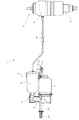
まず、本実施形態に係る締結部材を適用する自動車のエアサスペンション装置について、図3を参照して説明する。図3ではコンプレッサユニット3を車体に取付けるための取り付け部材であるコンプレッサユニットガイド12は一部のみ図示することとする。
First, an automobile air suspension device to which a fastening member according to this embodiment is applied will be described with reference to FIG. In FIG. 3, only a part of the
図3に示すように、エアサスペンション装置1は、ばね上、ばね下間、すなわち、車輪と車体との間に介装されるエアサスペンション2と、エアサスペンション2に圧縮空気を給排するためのコンプレッサユニット3とを備えている。 As shown in FIG. 3, the air suspension device 1 includes an air suspension 2 interposed between a sprung and unsprung state, that is, between a wheel and a vehicle body, and for supplying and discharging compressed air to and from the air suspension 2. And a compressor unit 3.
エアサスペンション2は、エアばね4とショックアブソーバ5とを一体化したものである。エアばね4は、そのばね力によって車体を支持するサスペンションスプリングであり、コンプレッサユニット3によって圧縮エアを給排することにより、車高調整を行うことができる。また、ショックアブソーバ5は、ばね上、ばね下間の振動を減衰するものである。 The air suspension 2 is obtained by integrating an air spring 4 and a shock absorber 5. The air spring 4 is a suspension spring that supports the vehicle body by its spring force, and the vehicle height can be adjusted by supplying and discharging compressed air by the compressor unit 3. The shock absorber 5 attenuates vibration between the sprung and unsprung parts.
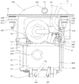
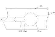
コンプレッサユニット3は、圧縮部6と、圧縮部6を駆動するモータ7と、圧縮部6の吐出口に接続されて圧縮空気の水分を吸着するエアドライヤ15と、エアばね4の圧縮空気の給排を制御する給排制御バルブ8とを備えており、これらは一体に結合されている。コンプレッサユニット3には、3つのブラケット9、27A、27Bが取付けられており、ブラケット9、27A、27Bがそれぞれネジ部材10によって防振装置11を介して車体側と接続される本発明のフレーム及び他側部材としてのコンプレッサユニットガイド12に結合されている。図3では1つの防振装置11のみ示すが、ブラケット9とコンプレッサユニットガイド12とは3箇所で防振装置11を介して結合されている。
The compressor unit 3 includes a
このコンプレッサユニット3とフレームとしてのコンプレッサユニットガイド12で本願発明のコンプレッサ装置を構成している。
The compressor unit 3 and the
圧縮部6の吸込口には、可撓性の吸気チューブ13、吸気フィルタ14が接続され、圧縮部6の吐出側に配されるエアドライヤ15は、エアライン16によって、図示しない分岐を介して各車輪に設けられたエアサスペンション2のエアばね4に接続されている。なお、分岐後のエアライン16とエアばね4の間には、開閉弁が設けられ、各車輪毎の車高調整を可能としている。
A
次に、図1、図2を用いて本発明のコンプレッサ装置を説明する。 Next, the compressor apparatus of the present invention will be described with reference to FIGS.
車体側パネル21は、車両のモノコックのボディやフレームであり、本発明の一側部材及び被取付部材を構成する。
The vehicle
コンプレッサユニット3は、コンプレッサユニットガイド12が車体側パネル21に対して2つの締結部材20(20A、20B)を介して結合されることで、車両に取り付けられる。
The compressor unit 3 is attached to the vehicle by connecting the compressor unit guide 12 to the vehicle
次に、締結部材20を介して車体側パネル21と結合される本願発明の他側部材及びフレームを構成するコンプレッサユニットガイド12について説明する。
Next, the compressor unit guide 12 constituting the frame and the other side member of the present invention which is coupled to the vehicle
図1、図2に示されるようにコンプレッサユニットガイド12は、エアドライヤ15とモータ7の間に設けられたU字状の第1底部12Aと、この第1底部12Aの図2における左右両側から上方に延びる2本の右側の側部12Bと左側の側部12Cと、第1底部12AのU字の2本の先端側に設けられ、傾斜部12Fを介して第1底部12A上より上側に位置する左右2つの第2底部12Dと、この2つの第2底部12D間を接続する逆さU字状の腕部12Eから大略構成される。
As shown in FIGS. 1 and 2, the
この右側の側部12Bと左側の側部12Cとの上端には、図2中水平方向に折れて延びるブラケット部12G、12Hが形成されている。このブラケット部12G、12Hには、円形の孔からなる挿通孔12I、12Jがそれぞれ設けられている。
また、腕部12Eには、後述の防振ブッシュ23が設けられる円形の孔12Kが設けられている。さらに、第1底部12AのU字の底部と左右2つの第2底部12Dには、防振装置11A、11B、11Cが取り付けられる孔12L、12M、12Nが形成されている。
In addition, the
圧縮部6のクランクケース6Aの端面6Bには、クランクケースブラケット27が設けられ、このクランクケースブラケット27には、クランクケース6Aの両側部から上方に延びるブラケット27A、27Bが一体的に形成されている。このブラケット27A、27Bには孔27A1、27B1が設けられている。また、モータ7の端面に設けられたブラケット9にも孔9Aが設けられ、孔9A、孔27A1、27B1と孔12L、12M、12Nとには、それぞれねじ部材10(10A、10B、10C)によって防振装置11A、11B、11Cが取り付けられている。これにより、コンプレッサユニット3の振動をコンプレッサユニットガイド12に直接伝えない構成とすることにより、車体側パネル21側にも伝えにくくしている。
A
コンプレッサユニットガイド12には、その他にマフラー等の外部からの熱や飛び石からモータをガイドするモータガイド26や延長ガイド28、コネクタ類が取り付けられるコネクタブラケット29が設けられている。
In addition, the
ここで、防振装置11について防振装置11Aを用いて詳述する。防振装置11Aは、コンプレッサユニットガイド12の第2底部12の孔12Lに嵌合されるアッパブッシュ11Dと、孔12Lに当接するロアブッシュ11Eと、アッパブッシュ11Dとロアブッシュ11Eに挿通されネジ部材10Aによって第2底部12Dに固定される構成となっている。
Here, the vibration isolator 11 will be described in detail using the
腕部12Eの一側には、後述の防振ブッシュ23が設けられる円形の孔12Kが設けられ、他側は第2底部12Dの両端部に溶接等の手段で一体的に取付けられ、孔12Kに設けられた防振ブッシュ23を介して車体側パネル21に締結されている。本実施の形態では車体側パネル21のブッシュ取付孔24の径よりも自然状態で大きい径であるゴム材で形成した防振ブッシュ23を圧入嵌合させる構成としているが、ゴム材のブッシュに限らず、例えば防振装置11を用いてもよい。
A
次に、コンプレッサユニットガイド12に接続され、コンプッサ6およびモータ7をガイドするモータガイド26について説明する。モータガイド26は、モータ7の側面を覆うモータカバー部26Aと、コンプレッサ6をガイドし、コンプレッサユニットガイド12の第2底部12Dと接続されるコンプレッサカバー部26Bとから構成されている。モータカバー部26Aは、一側がコンプレッサカバー部26Bと一体的に接続され、他側がコンプレッサユニットガイド12の側部に複数のネジ26Cにより締結されている。モータカバー部26Aとコンプレッサカバー部26Bとは、底部以外は接していない構成となっている。モータカバー部26Aとコンプレッサカバー部26Bとでコンプレッサ6およびモータ7を全周に亘って覆わないことにより、コンプレッサ6およびモータ7の熱を外部へ逃がしやすくし、コンプレッサ6およびモータ7の耐久性、信頼性を向上することができ、さらには軽量化を図ることができる。また、コンプレッサガイド27およびモータ7とは隙間をもって配置されるため、さらに熱を外部へ逃がしやすくしている。
Next, the
次にクランクケースブラケット27について説明する。
Next, the
クランクケースブラケット27とクランクケース6Aとは、図示はしないが例えば4箇所ネジにより結合されており、コンプレッサ6のガイドおよび防振装置11Aのブラケットとしての役割をしている。
Although not shown, the
次に延長ガイド28について説明する。延長ガイド28は樹脂で形成されており、モータガイド26の底部及びモータカバー部26Aの内周側に亘って配されるようモータガイド26に締結されて固定される。これにより、車の走行中に飛び石があったとしても、モータ7には直接当たることがないので、モータ7を保護することができる。
Next, the
次にコネクタブラケット29について説明する。コネクタブラケット29は、略L字型に構成され、一側がコンプレッサユニットガイド12に例えば溶接により一体的に締結され、他側はモータガイド26に対し隙間をもって配置される。コネクタブラケット29には電源線39が挿入される挿入孔29Aが形成され、挿入孔29Aには、電源線39が挿入され、電源線39の一側は図示しないが車のバッテリに接続され、他側はモータ7、コンプレッサ6に取付けられる排気のための排気電磁弁25に接続される電源線39B、およびモータ7及びエアサスペンション2への圧縮空気の給気、排気を切換える切換え電磁弁32に接続される電源線39Aとなっている。
Next, the
切換え電磁弁32には、一側がドライア15に接続される金属製のエアライン16Aに接続され、他側がエアサスペンション2に圧縮空気を給気、排気する可撓性のエアチューブ16B、16Cと接続される。エアチューブ16Bは車の右側に取り付けられるエアサスペンション2に、エアチューブ16Cは車の左側に取付けられるエアサスペンション2にそれぞれ接続される。
One side of the switching
このように、振動源である圧縮部6の振動は、防振装置11により振動を直接コンプレッサユニットガイド12に伝えない構成とし、さらに締結部材20(20A、20B)を介して車体側パネル21と締結する構成、つまり2重に防振する構成としている。
As described above, the vibration of the
次に、主に図4乃至図10を参照して締結部材20について説明する。
Next, the
締結部材20は、ボルト30、ワッシャ31、ナット32、弾性体33、筒状部材34から構成されている。そして、締結部材20は、車体側パネル21の本発明の取付孔としての長孔部22Cに挿通され、ボルト30の頭部30Aとワッシャ31とで車体側パネル21を挟持し、コンプレッサユニットガイド12の取付孔12I、12Jに弾性体33を介して結合される。次に締結部材20の構成部品について詳述する。なお、図4は、ナット32を最後まで締め付けていない仮止め状態を示している。
The
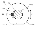
ボルト30は、図6に示されるように一側部材としての車体側パネル21に係合されるボルト30の基端側に設けられた頭部30Aと、取付孔22C及びワッシャ31との相対回転を規制する非円形の相対回転規制部30Bと、ボルト30の先端側であって雄ネジが切られたネジ部30Cと、ボルト30の先端であって雄ネジが切られていない非ネジ部30Dとから構成されている。この相対回転規制部30B、ネジ部30C、非ネジ部30Dとで本発明の軸部を構成している。
As shown in FIG. 6, the
頭部30Aの外形は図6のA−A断面図である図7に示されるように、円形部30Fと切欠部30Eとから構成されている。切欠部30Eは、回転方向の位置決めのための目印として設けられ、平坦部30Hと平行に延びており、平坦部30Hが見えない方向からでも視認部としての切欠部30Eを見ることで、平坦部30Hの向きを知ることができる。これにより視認性を高めている。また、円形部30Fは、後述のように車体側パネル21の取付部22の長孔部22Cの幅方向の長さYより大きく円形孔22Aより小さく、円形孔22Aから挿入可能で、長孔部22Cからは抜けずに係合する形状となっている。
The outer shape of the
相対回転規制部30Bの外形は半円分の円形部30Gと円形部30Gのそれぞれの端から延びる平坦部30Hと、2辺の平坦部30Hの端部に設けられたR部30Iとから構成されている。この平坦部30HとR部30Iとで、径方向突出部30Lを形成している。
The outer shape of the relative
R部30Iには頭部30A側からネジ部30C側に向けて複数の縦溝状のローレット部30Jが形成されている。これは、後述するワッシャ31の挿通孔31Aが圧入された後、相対回転規制部30Bに対しワッシャ31の軸方向に所定の拘束力(抵抗力)で固定し、仮止め状態を可能とするために設けられている。この拘束力は、ナット32の締め付けによっては、移動可能な程度で、仮止め状態で振動等では移動不能な程度の拘束力(抵抗力)である。なお、ローレット部30Jは、圧入し易くかつ抜けにくいので設けることが望ましいが、必須ではない。
In the R portion 30I, a plurality of longitudinal groove-shaped
そして、径方向突出部30Lにより長孔部22C及びワッシャ31の挿通孔31Aに対する位置決め及び回転規制を行なう役目を担っている。ネジ部30Cは外形が円形であり、相対回転規制部30Bの端から先端側に向けて雄ネジが切られている。本実施の形態では、ネジ部30Cが相対回転規制部30Bから先端の非ネジ部30Dまで全体に亘って雄ネジを形成する構成としたが、ナット32を締め上げる箇所にのみ雄ネジが切られていればよい。
And it has a role which performs positioning and rotation control with respect to
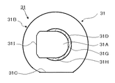
次にワッシャ31について図8、図9を用いて説明する。図8はワッシャ31単体の平面図、図9は図8のB−B断面図である。
Next, the
ワッシャ31の円形部31Bの外径はボルト30の頭部30A及び弾性体33よりも大径である。ワッシャ31の外形は、円形部31Bと切欠部31Cとから構成されている。切欠部31Cは、平坦部31Hと平行となっており、平坦部31Hが見えない状態でも視認部としての切欠部31Cを見ることで、回転方向がわかり、位置決めの目印として設けられ、これにより視認性を高めている。
The outer diameter of the
ワッシャ31の内周側には弾性体33の内周側に嵌合される嵌合部31Dが周方向部分的に設けられている。嵌合部31Dは弾性体33の内周側に嵌合することで組みやすくなり、生産性の向上を図ることができ、また、ナット32を締め上げる際に筒状部材34と当接して、軸力を入れることで、ナット32の緩みを防止する。また、筒状部材34の底部34Aと円形部31Bとの間の軸方向寸法Wを出すことで、弾性部材33の軸方向の位置決めを行うことができる。さらに、必要に応じて、軸方向寸法Wより弾性部材33の軸方向寸法を大きくすることで、軸方向の圧縮力を入れることができる。
On the inner peripheral side of the
なお、本実施の形態では嵌合部31Dを設ける構成としたが、嵌合部31Dを無くすこともできる。その際、筒状部材34をワッシャ31に当接する位置まで延ばすことで軸力を入れることが可能となり、組立性は多少劣るものの嵌合部31Dを有するものと同様の効果を奏することができる。
In the present embodiment, the
また、ワッシャ31の内周には、貫通孔31Aが設けられ、平坦部31Hと2辺の平坦部31Hの端部に設けられた円形部31G及び相対回転規制部30Bと当接する曲面部31Iとから構成され、ボルト30の相対回転規制部30Bが圧入可能な略同形上となっている。
Further, a through
弾性体33は外周の軸方向の中間部に、周方向に延びる凹み部33Aが形成されている。この凹み部33Aがコンプレッサユニットガイド12の挿通孔12I、12Jの周囲に嵌合することで、弾性体33がコンプレッサユニットガイド12に取り付けられる。この弾性体33はコンプレッサユニットガイド12に取付けられた状態で、摩擦力及び凹み部33Aの緊迫力により振動程度では、容易に回転しない。
The
弾性体33の内周側には筒状部材34が挿入される筒状部材34とほぼ同径の貫通孔33Bが形成されている。本実施の形態の弾性体33はシリコンゴム、ウレタンゴムなどのゴム材を用いている。コンプレッサ6が発生する振動周波数に応じて弾性体33の材質、及びばね定数を適宜変更することで、振動の吸収を高めることができる。また、ゴム材を用いているので、金属材料で形成されたコンプレッサガイド12に対し摩擦係数が高いので、挿通孔12I、12Jに対して弾性体33が回転するのを防止している。さらに、弾性体33の内周側には段部33Cが設けられ、段部33Cには嵌合部31Dを嵌合させることで組立性を向上させている。
A through
筒状部材34は円形の底部34Aと筒部34Bとからなり、底部34A及び筒部34Bの内周側には貫通孔34Cが形成されている。弾性体33の貫通孔33Bの内径よりも筒状部材34の貫通孔34Cの外径のほうが僅かに大きいため、筒状部材34に対して弾性体33は圧入状態で組みつけられる。筒状部材34は弾性体33を軸方向又は周方向内側の少なくとも一方の変形を規制し(本実施例では両方を規制)、またナット32の締め上げトルクをワッシャ31に伝える機能を有する。
The
ナット32は筒状部材34の円形の底部34Aと当接するフランジ部32Aと6角形の筒部32Bとから構成され、筒部32Bの内周側には雌ネジ部32Cが形成される。
The
次に、締結部材20が組みつけられる車体側パネル21の取付部22について図10を用いて説明する。図10は、図1の上方から見た図面である。
Next, the
取付部22は、円形孔22Aと、この円形孔22Aの開放部22Bから図1の図中左方向に延びる本発明の取付孔となる長孔部22Cとから大略構成されている。長孔部22Cと円形孔22Aとの接続部分は本願発明の開放部22Bを形成している。円形孔22Aはボルト30の頭部30Aの外径よりも大径に構成され、頭部30Aが挿通可能となっている。長孔部22Cの幅方向の長さYは、相対回転規制部30Bの幅方向の長さZとほぼ同じか僅かに長く、かつ、頭部30Aの最小径部より短く形成される。これにより、ボルト30を円形孔22Aから挿入し、開放部22Bから長孔部22Cに移動させることで、相対回転規制部30Bが長孔部22Cと回転方向で当接しボルト30が相対回転することを規制、位置決めすることができ、また、頭部30Aが抜けないので、軸方向の位置決めも行うことができる。
The
次に図1を用いてコンプレッサユニットガイド12に結合されたコンプレッサユニット3を車体に組付ける組立手順について説明する。 Next, an assembly procedure for assembling the compressor unit 3 coupled to the compressor unit guide 12 to the vehicle body will be described with reference to FIG.
まず、ボルト30の相対回転規制部30Bにワッシャ31を圧入する。その際、相対回転規制部30Bとワッシャ31の挿通孔31Aとは、回転方向の位置、つまりそれぞれの平坦部30H、31Hを併せて嵌合させ、頭部30Aからの距離Xの位置まで圧入する。ここで、頭部30Aからの距離Xは車体側パネル21の厚みよりも僅かに長い距離である。このボルト30へのワッシャ31の圧入作業により、ボルト30とワッシャ31との回転方向の位置決めと、車体側パネル21に対する締結部材20の軸方向の位置決めを行なうことができる。
First, the
次に、コンプレッサユニットガイド12の挿通孔12I、12Jに弾性体33を挿入し、挿通孔12I、12Jに弾性部材33の凹み部33Aが嵌合する位置まで挿入する。その後、弾性部材33の内周孔33Bに筒状部材34を下方から挿入する。これにより、弾性部材33は内周方向への変形ができなくなるので、挿通孔12I、12Jから外れることは無くなる。
Next, the
その後、ワッシャ31が圧入されたボルト30をコンプレッサユニットガイド12の上方から弾性体33の貫通孔33B(筒状部材34の貫通孔34C)に挿入する。その際、頭部30Aに設けた切欠部30Eを図1の手前側にすることにより、車両に取り付けるときに、取付部22の長孔部22Cにボルト30の円形部30G側からスムーズに挿入可能となる。なお、コンプレッサユニットガイド12に切欠部30Eの向きの目印をプレス等でつけておくことで、容易に向きを合わせることが可能となる。
Thereafter, the
最後にナット32を下方からボルト30に挿通させてコンプレッサユニットガイド12に対し締結部材20を仮止めする。このとき、ワッシャ31が相対回転規制部30Bに圧入されて軸方向へ所定の拘束力で固定されているので、この拘束力以下の力が加わらない程度の力で締付ける。これにより、ワッシャ31とボルト30の頭部30Aとの距離Xを保った状態で、仮止めされる。この状態で、自動車組立てラインに出荷する。
Finally, the
自動車組立てラインでは、締結部材20(20A、20B)をコンプレッサユニットガイド12の挿通孔12I、12Jにそれぞれ仮止めした状態で、車体側パネル21に対し下方からコンプレッサユニット3を組み付ける。まず、取付部22の円形孔22Aにボルト30の頭部30Aを挿通させるように、下方から上方に向けてコンプレッサユニット3を移動させる。頭部30Aを挿通させてから軸方向に移動させると、円形孔22Aの外径よりも大径であるワッシャ31が円形孔22Aの周囲に当接するので、この位置まできたら、取付部22の長孔部22Cに向けてコンプレッサユニット3を(図1中左方向へ)スライドさせる。
In the automobile assembly line, the compressor unit 3 is assembled to the vehicle
その際、作業者からは取付部22以外、車体側パネル21に覆われており、車体側パネル21より上方の様子が見えないが、仮止め状態でボルト30の向きが、取付部22の長孔部22Cにボルト30の円形部30G側からスムーズに挿入可能な向きとなっているので、防振ブッシュ23がコンプレッサユニットガイド12の孔12Kに圧入される位置までスライドさせることで、コンプレッサユニット3を車体の取付位置に配置することができる。
At this time, the operator is covered with the vehicle
なお、仮に、輸送中にボルト30が回転し向きが変わってしまったとしても、作業者は、車体側パネル21の下側から見えるワッシャ31の平坦部、つまり視認部を用いて車体側パネル21に対する回転方向の位置決めを行なうことができる。
Even if the
最後にナット32を締めることで、締め上げトルクが筒状部材34、ワッシャ31に加わり、頭部30Aとワッシャ31とで、車体側パネル21の長孔部22Cの周囲を挟持し、固定される。相対回転規制部30Bにローレット部30Jを形成したことにより、相対回転規制部30Bに対してワッシャ31を圧入し、仮止めすることができる。また、ナット32、筒状部材34、ワッシャ31の突出部31Dが軸方向に隙間無く接する構成としているので、ナット32の締め付けトルクを十分に伝えることが可能である。
Finally, the tightening torque is applied to the
このとき、ワッシャ31が相対回転規制部30Bに圧入されているので、ワッシャ31が相対回転規制部30Bから外れて回転方向が合わずに、相対回転規制部30Bの下面30Kと当接する位置で締め上げてしまい長孔部22Cの周囲をワッシャ31と頭部30Aで狭持させることが出来ないという事態を防止することができる。
At this time, since the
また、ワッシャ31が相対回転規制部30Bに圧入されており、円形孔22Aの外径よりもワッシャ31を大径としているので、車体側パネル21に対するコンプレッサ装置の軸方向の位置決めをすることができる。
Further, since the
以上説明した実施の形態は、本発明の一実施の形態に過ぎず、以下のような変形例も考えられる。 The embodiment described above is merely one embodiment of the present invention, and the following modifications are also conceivable.
本実施の形態は、本発明の締結部材を車載用のコンプレッサ装置に用いられた例を示したが、一側部材としては、車両に限らず、各種機械、住宅、各種筐体などであってもよく、他側部材としては、振動するものに用いることが望ましく、モータ、エンジン等の駆動手段が内在された装置に用いることができる。 In the present embodiment, an example in which the fastening member of the present invention is used in a vehicle-mounted compressor device is shown. However, the one-side member is not limited to a vehicle, and includes various machines, houses, various cases, and the like. In addition, the other side member is preferably used for a vibrating member, and can be used for a device in which driving means such as a motor or an engine is incorporated.
また、上記実施の形態では、一側部材を車両として、コンプレッサユニットガイド12を他側部材とし例を示したが、これらを入れかえてもよい。この場合、例えば、締結部材20を車両側に設けておき、取付部22をコンプレッサユニットガイド12に設ければよい。
Moreover, in the said embodiment, although the one side member was used as the vehicle and the
上記実施の形態では、取付部22は、円形孔22Aと、この円形孔22Aから延びる長孔部22Cとから大略構成される例を示したがこれに限らず、取付部にボルト30の頭部30Aが抜けない取付孔と、ボルト30にナット等付けた状態で挿入できる開放部があればよく、例えば長孔部22Cの一端が板材の端部となり、この端部を開放部とすることで取付孔を形成してもよい。この場合、板材の端部からボルト30を挿入することになるので、コンプレッサユニット3を水平方向に動かすのみで取り付けることができる。
In the above-described embodiment, the mounting
なお、上記実施の形態では、ワッシャ31に切欠き31Cを設けて、相対回転規制部30Bの向きを下方からわかるようにしたが、これに代えて、非ネジ部30Dに切欠き等の目印を設けて相対回転規制部30Bの向きをわかるようにしてもよい。
In the above embodiment, the notch 31C is provided in the
また、上記実施の形態では、弾性部材33、筒状部材34を設けた例を示したが、防振性を必要としないものにあっては、これらを設けなくともよい。
Moreover, in the said embodiment, although the example which provided the
さらに、図11、図12示すような変形例も考えられる。なお、図11、12においては、上記実施の形態と同様の部材には、上記実施の形態の図番に100を足した図番で表示し、詳細な説明は省略する。 Furthermore, a modification as shown in FIGS. 11 and 12 is also conceivable. 11 and 12, members similar to those in the above embodiment are indicated by a figure number obtained by adding 100 to the figure number in the above embodiment, and detailed description thereof is omitted.
ボルト130には、前記実施の形態では、片側のみに設けていた径方向突出部30Lを両側に径方向突出部130Lとして設けている。これにより、ワッシャ131の貫通孔131Aを円形にした場合であっても、ワッシャ131の中心軸とボルト130のネジ部130Cの中心軸が同軸とすることができる。
The
このように、上記実施の形態では、ワッシャ31の貫通孔31Aを相対回転規制部30Bと同形上としていたが、ワッシャの貫通孔と相対回転規制部との形状を異ならせても、圧入可能であればよい。
As described above, in the above embodiment, the through
また、この変形例においては、ワッシャ131を安価な単なる環状のディスクとした。そして、筒状部材134の上端面を延ばし、ワッシャ131の下面と当接する形状とすることで、ナット132の軸力を伝えられるようにした。
In this modification, the
3 コンプレッサユニット、12 コンプレッサユニットガイド(他側部材)、12I、12J 挿通孔、20 締結部材、21 車体側パネル(一側部材、被取付部材)、22 取付部、22B 開放部、22C 長孔部(取付孔)、30 ボルト、30A 頭部、30B 相対回転規制部、31 ワッシャ、31A 貫通孔、32 ナット 3 compressor unit, 12 compressor unit guide (other side member), 12I, 12J insertion hole, 20 fastening member, 21 vehicle body side panel (one side member, attached member), 22 mounting portion, 22B open portion, 22C long hole portion (Mounting hole), 30 bolt, 30A head, 30B relative rotation restricting portion, 31 washer, 31A through hole, 32 nut
Claims (14)
前記取付孔の前記開放部から前記取付孔に挿通される少なくとも先端側に雄ねじが形成された軸部と、該軸部の基端側に形成され該軸部が前記取付孔に挿通された状態で、該取付孔を通過できない形状の頭部と、を有し、前記軸部に前記他側部材が取付けられるボルトと、
該ボルトの前記軸部が挿通する貫通孔を有し、前記ボルトと相対回転が規制され、前記一側部材を前記頭部との間で挟持するワッシャと、
前記ボルトと螺合し、前記一側部材と前記他側部材とを結合するナットと、
からなり、
前記ボルトの前記軸部の前記頭部側には、前記取付孔の前記非円形部と回転方向に当接することで、前記ボルトと前記一側部材との相対回転を規制する非円形の相対回転規制部が設けられることを特徴とする締結部材。 A fastening member used for coupling one side member having a non-circular mounting hole in which an open part is formed in a part of the periphery and the other side member having an insertion hole,
A shaft portion in which a male screw is formed at least on the distal end side, which is inserted into the mounting hole from the open portion of the mounting hole, and a state where the shaft portion is formed on the proximal end side of the shaft portion and is inserted into the mounting hole. And a head having a shape that cannot pass through the mounting hole, and a bolt to which the other side member is attached to the shaft portion,
A washer having a through-hole through which the shaft portion of the bolt is inserted, relative rotation with the bolt being restricted, and sandwiching the one side member with the head;
A nut that is screwed into the bolt and connects the one side member and the other side member;
Consists of
A non-circular relative rotation that restricts the relative rotation between the bolt and the one-side member by contacting the non-circular portion of the mounting hole in the rotational direction on the head side of the shaft portion of the bolt. A fastening member provided with a restricting portion.
該圧縮部が取り付けられるフレームと、
該フレームに設けられた挿通孔と、
該挿通孔に挿入され、外周において前記挿通孔と係合する筒状の弾性体と、
前記弾性体に挿入され、軸部の基端側に頭部が設けられ先端側に雄ねじが形成されたボルトと、
前記ボルトに螺合するナットと、からなるコンプレッサ装置において、
前記ボルトの前記軸部が挿通する貫通孔を有し、前記ボルトと相対回転が規制され、前記頭部との間で、該コンプレッサ装置が取付られる被取付部材に設けられた非円形の取付孔の周囲を挟持するワッシャと、
前記ボルトの前記軸部には、前記頭部側に前記取付孔の前記非円形部に回転方向に当接することで、前記ボルトと前記被取付部材との相対回転を規制する非円形の相対回転規制部が設けられることを特徴とするコンプレッサ装置。 A compression section for compressing air;
A frame to which the compression unit is attached;
An insertion hole provided in the frame;
A cylindrical elastic body inserted into the insertion hole and engaged with the insertion hole on the outer periphery;
A bolt inserted into the elastic body, a head is provided on the proximal end side of the shaft portion, and a male screw is formed on the distal end side; and
In a compressor device comprising a nut screwed into the bolt,
A non-circular mounting hole provided in a mounting member to which the compressor device is mounted between the bolt and a through hole through which the shaft portion of the bolt is inserted, relative rotation with the bolt being restricted A washer that sandwiches the periphery of
A non-circular relative rotation that restricts relative rotation between the bolt and the mounted member by contacting the non-circular portion of the mounting hole on the shaft portion of the bolt in the rotational direction on the head side. A compressor device provided with a regulating part.
Priority Applications (4)
| Application Number | Priority Date | Filing Date | Title |
|---|---|---|---|
| JP2012082036A JP2013210079A (en) | 2012-03-30 | 2012-03-30 | Fastening member and compressor apparatus |
| US13/837,805 US8821092B2 (en) | 2012-03-30 | 2013-03-15 | Fastening member and compressor apparatus |
| DE102013204583A DE102013204583A1 (en) | 2012-03-30 | 2013-03-15 | Fastener and compressor device |
| CN201310232630.7A CN103363014B (en) | 2012-03-30 | 2013-03-28 | Coupling component and compressor plant |
Applications Claiming Priority (1)
| Application Number | Priority Date | Filing Date | Title |
|---|---|---|---|
| JP2012082036A JP2013210079A (en) | 2012-03-30 | 2012-03-30 | Fastening member and compressor apparatus |
Publications (2)
| Publication Number | Publication Date |
|---|---|
| JP2013210079A true JP2013210079A (en) | 2013-10-10 |
| JP2013210079A5 JP2013210079A5 (en) | 2015-03-19 |
Family
ID=49154924
Family Applications (1)
| Application Number | Title | Priority Date | Filing Date |
|---|---|---|---|
| JP2012082036A Pending JP2013210079A (en) | 2012-03-30 | 2012-03-30 | Fastening member and compressor apparatus |
Country Status (4)
| Country | Link |
|---|---|
| US (1) | US8821092B2 (en) |
| JP (1) | JP2013210079A (en) |
| CN (1) | CN103363014B (en) |
| DE (1) | DE102013204583A1 (en) |
Cited By (1)
| Publication number | Priority date | Publication date | Assignee | Title |
|---|---|---|---|---|
| JP2016167988A (en) * | 2015-03-11 | 2016-09-23 | 株式会社クボタ | Combine harvester |
Families Citing this family (19)
| Publication number | Priority date | Publication date | Assignee | Title |
|---|---|---|---|---|
| CN105492227B (en) | 2013-03-13 | 2017-11-21 | 博格思众公司 | Use the air-conditioning system for fresh air supply and the recuperation of heat ventilation blower of climate controlling |
| WO2015065495A1 (en) | 2013-11-04 | 2015-05-07 | Bergstrom, Inc. | Low profile air conditioning system |
| DE102014224050A1 (en) * | 2013-11-25 | 2015-05-28 | Continental Teves Ag & Co. Ohg | Highly damped bearing element |
| FR3022307B1 (en) * | 2014-06-16 | 2017-02-17 | Renault Sa | "DEVICE FOR ATTACHING AN ACCESSORY TO A FUEL TANK OF A MOTOR VEHICLE" |
| US9783024B2 (en) | 2015-03-09 | 2017-10-10 | Bergstrom Inc. | System and method for remotely managing climate control systems of a fleet of vehicles |
| US9874384B2 (en) | 2016-01-13 | 2018-01-23 | Bergstrom, Inc. | Refrigeration system with superheating, sub-cooling and refrigerant charge level control |
| US10589598B2 (en) * | 2016-03-09 | 2020-03-17 | Bergstrom, Inc. | Integrated condenser and compressor system |
| MA45487A (en) * | 2016-03-15 | 2019-01-23 | Quadro Vehicles S A | IMPROVED SUSPENSION |
| US10081226B2 (en) | 2016-08-22 | 2018-09-25 | Bergstrom Inc. | Parallel compressors climate system |
| US10562372B2 (en) | 2016-09-02 | 2020-02-18 | Bergstrom, Inc. | Systems and methods for starting-up a vehicular air-conditioning system |
| US10675948B2 (en) | 2016-09-29 | 2020-06-09 | Bergstrom, Inc. | Systems and methods for controlling a vehicle HVAC system |
| US10724772B2 (en) | 2016-09-30 | 2020-07-28 | Bergstrom, Inc. | Refrigerant liquid-gas separator having an integrated check valve |
| US10369863B2 (en) | 2016-09-30 | 2019-08-06 | Bergstrom, Inc. | Refrigerant liquid-gas separator with electronics cooling |
| US11448441B2 (en) | 2017-07-27 | 2022-09-20 | Bergstrom, Inc. | Refrigerant system for cooling electronics |
| US11420496B2 (en) | 2018-04-02 | 2022-08-23 | Bergstrom, Inc. | Integrated vehicular system for conditioning air and heating water |
| US11078985B2 (en) * | 2019-09-05 | 2021-08-03 | Hyundai Motor Company | Compressor mounting device for vehicle |
| TWI732712B (en) * | 2020-11-11 | 2021-07-01 | 明安國際企業股份有限公司 | Wheel frame |
| CN112664599B (en) * | 2020-12-11 | 2022-07-15 | 杭州钱江制冷压缩机集团有限公司 | Buffering and damping device for compressor movement |
| CN113530950B (en) * | 2021-07-19 | 2023-03-31 | 海盐猛凌汽车配件有限公司 | Adjustable bolt |
Citations (6)
| Publication number | Priority date | Publication date | Assignee | Title |
|---|---|---|---|---|
| JPS60175610U (en) * | 1984-04-30 | 1985-11-21 | 大和鉄鋼株式会社 | Tightening structure of concrete formwork equipment |
| JPH0658180U (en) * | 1993-01-06 | 1994-08-12 | 三菱重工業株式会社 | Anti-vibration device for compressor |
| JPH06313420A (en) * | 1993-04-28 | 1994-11-08 | Asahi Tec Corp | Metal fixture for architecture |
| JP2001159406A (en) * | 1999-12-01 | 2001-06-12 | Kojima Press Co Ltd | Installing structure using nut and bolt |
| JP2005291278A (en) * | 2004-03-31 | 2005-10-20 | Nissin Kogyo Co Ltd | Galvanic corrosion preventing bolt, and brake apparatus for vehicle |
| JP2007239932A (en) * | 2006-03-10 | 2007-09-20 | Thermatronics Boeki Kk | Fastening device, and fastening method using the fastening device |
Family Cites Families (18)
| Publication number | Priority date | Publication date | Assignee | Title |
|---|---|---|---|---|
| US2359046A (en) * | 1942-10-03 | 1944-09-26 | Westinghouse Electric & Mfg Co | Bolting apparatus |
| US2458382A (en) * | 1946-02-14 | 1949-01-04 | Eastman Kodak Co | Shock testing |
| US3032089A (en) * | 1959-05-07 | 1962-05-01 | Illinois Tool Works | Lock washer |
| US3747168A (en) * | 1971-11-08 | 1973-07-24 | Gen Motors Corp | Clamp assembly |
| US4435100A (en) * | 1981-12-21 | 1984-03-06 | Mcdonnell Douglas Corporation | Fail-safe zero-load hinge/pivot |
| US5234236A (en) * | 1992-12-03 | 1993-08-10 | Southco, Inc. | Pawl assembly |
| US5413442A (en) * | 1993-09-21 | 1995-05-09 | Barnes Group, Inc. | Bolt-nut assembly for railroad crossing frogs |
| US5628599A (en) * | 1995-07-17 | 1997-05-13 | Eakin; Karl F. | Anchored fastener |
| JP4286972B2 (en) * | 1998-07-31 | 2009-07-01 | 株式会社日立製作所 | air compressor |
| US6461092B2 (en) * | 2001-02-22 | 2002-10-08 | Shao-Chien Tseng | Anti-dead locking, anti-vibration and loosening-proof bolt/nut structure |
| US20060104825A1 (en) * | 2003-09-24 | 2006-05-18 | Etter Mark A | Air compressor |
| WO2005052386A2 (en) * | 2003-11-19 | 2005-06-09 | Alpha Stamping Company | Fastener assembly |
| JP2008106927A (en) | 2006-04-28 | 2008-05-08 | Hitachi Ltd | Vibration damper |
| US7758027B2 (en) | 2006-04-28 | 2010-07-20 | Hitachi, Ltd. | Vibration damper |
| US7874777B1 (en) * | 2007-07-16 | 2011-01-25 | The Grigoleit Company | Tapered sleeve, bolt, nut and washer device |
| CN102146953A (en) * | 2010-02-09 | 2011-08-10 | 鸿富锦精密工业(深圳)有限公司 | Fastening member and fixing structure using same |
| JP2012082036A (en) | 2010-10-08 | 2012-04-26 | Canon Inc | Sheet transporting device and image forming apparatus |
| US8545154B2 (en) * | 2011-04-18 | 2013-10-01 | Cruiser Accessories, Llc | License plate fastener |
-
2012
- 2012-03-30 JP JP2012082036A patent/JP2013210079A/en active Pending
-
2013
- 2013-03-15 US US13/837,805 patent/US8821092B2/en active Active
- 2013-03-15 DE DE102013204583A patent/DE102013204583A1/en not_active Withdrawn
- 2013-03-28 CN CN201310232630.7A patent/CN103363014B/en active Active
Patent Citations (6)
| Publication number | Priority date | Publication date | Assignee | Title |
|---|---|---|---|---|
| JPS60175610U (en) * | 1984-04-30 | 1985-11-21 | 大和鉄鋼株式会社 | Tightening structure of concrete formwork equipment |
| JPH0658180U (en) * | 1993-01-06 | 1994-08-12 | 三菱重工業株式会社 | Anti-vibration device for compressor |
| JPH06313420A (en) * | 1993-04-28 | 1994-11-08 | Asahi Tec Corp | Metal fixture for architecture |
| JP2001159406A (en) * | 1999-12-01 | 2001-06-12 | Kojima Press Co Ltd | Installing structure using nut and bolt |
| JP2005291278A (en) * | 2004-03-31 | 2005-10-20 | Nissin Kogyo Co Ltd | Galvanic corrosion preventing bolt, and brake apparatus for vehicle |
| JP2007239932A (en) * | 2006-03-10 | 2007-09-20 | Thermatronics Boeki Kk | Fastening device, and fastening method using the fastening device |
Cited By (1)
| Publication number | Priority date | Publication date | Assignee | Title |
|---|---|---|---|---|
| JP2016167988A (en) * | 2015-03-11 | 2016-09-23 | 株式会社クボタ | Combine harvester |
Also Published As
| Publication number | Publication date |
|---|---|
| US8821092B2 (en) | 2014-09-02 |
| CN103363014A (en) | 2013-10-23 |
| CN103363014B (en) | 2019-04-26 |
| US20130259596A1 (en) | 2013-10-03 |
| DE102013204583A1 (en) | 2013-10-02 |
Similar Documents
| Publication | Publication Date | Title |
|---|---|---|
| JP2013210079A (en) | Fastening member and compressor apparatus | |
| US5718407A (en) | Power unit mounting system | |
| US8544591B2 (en) | Bearing device for the vibration-decoupled rotatable support of an intermediate shaft on the engine block of a motor vehicle, and method for the vibration-decoupled rotatable support of an intermediate shaft on the engine block of a motor vehicle | |
| JP6045257B2 (en) | Vibration isolator | |
| US20160053848A1 (en) | Tubular vibration-damping device used for vibration-damping connecting rod, vibration-damping connecting rod using the same, and method of manufacturing vibration-damping connecting rod | |
| US20130056613A1 (en) | Grommet Mounting Assembly | |
| KR101220807B1 (en) | a rear shock absorber installing apparatus for a vehicle | |
| CN110709264B (en) | Joint structure of stabilizer link | |
| JP2004092803A (en) | Cylindrical vibration controller | |
| JP2002174289A (en) | Vibration damping bolt and fastening structure with vibration damping function imparted thereto | |
| EP2390503B1 (en) | Compressor for vehicle air-conditioners | |
| US20230340950A1 (en) | Damper System and Acoustic Bushing for a Vehicle | |
| JPH11270606A (en) | Connection structure | |
| WO2012132105A1 (en) | Vibration prevention device | |
| JP2005147226A (en) | Fastening member with damping function, and vibration control device using its fastening member | |
| JPH09240290A (en) | Vibration damping device for power unit | |
| JPH08326811A (en) | Vibration control device | |
| KR200311780Y1 (en) | Installation structure of compressor for vehicle | |
| US20110147150A1 (en) | Attachment arrangement for a refrigerant compressor | |
| JP6189665B2 (en) | Vibration isolator | |
| CN216942602U (en) | Suspension assembly and car | |
| JP5621719B2 (en) | Electric compressor mounting structure | |
| KR20040035261A (en) | structure of engine mount assembly for vehicle | |
| JP2001173544A (en) | Structure for mounting engine starter | |
| KR100836925B1 (en) | Engine mount unit in vehicle |
Legal Events
| Date | Code | Title | Description |
|---|---|---|---|
| A521 | Request for written amendment filed |
Free format text: JAPANESE INTERMEDIATE CODE: A523 Effective date: 20150127 |
|
| A621 | Written request for application examination |
Free format text: JAPANESE INTERMEDIATE CODE: A621 Effective date: 20150127 |
|
| A977 | Report on retrieval |
Free format text: JAPANESE INTERMEDIATE CODE: A971007 Effective date: 20151015 |
|
| A131 | Notification of reasons for refusal |
Free format text: JAPANESE INTERMEDIATE CODE: A131 Effective date: 20151020 |
|
| A02 | Decision of refusal |
Free format text: JAPANESE INTERMEDIATE CODE: A02 Effective date: 20160308 |