JP2013146834A - Suction nozzle and part mounting device - Google Patents
Suction nozzle and part mounting device Download PDFInfo
- Publication number
- JP2013146834A JP2013146834A JP2012009875A JP2012009875A JP2013146834A JP 2013146834 A JP2013146834 A JP 2013146834A JP 2012009875 A JP2012009875 A JP 2012009875A JP 2012009875 A JP2012009875 A JP 2012009875A JP 2013146834 A JP2013146834 A JP 2013146834A
- Authority
- JP
- Japan
- Prior art keywords
- nozzle
- suction
- component
- base
- nozzle base
- Prior art date
- Legal status (The legal status is an assumption and is not a legal conclusion. Google has not performed a legal analysis and makes no representation as to the accuracy of the status listed.)
- Granted
Links
Images


Abstract
Description
本発明は、部品実装装置が備える装着ヘッドに取り付けられ、下端の吸着孔から真空吸引することによって部品を吸着する吸着ノズル及びこの吸着ノズルを備えた部品実装装置に関するものである。 The present invention relates to a suction nozzle that is attached to a mounting head provided in a component mounting apparatus and sucks a component by vacuum suction from a suction hole at a lower end, and a component mounting apparatus including the suction nozzle.
部品実装装置は所定の位置に位置決めした基板に対して電子部品等の部品を装着する装置であり、部品の装着には基板に対して移動自在に設けられた装着ヘッドが用いられる。装着ヘッドには下端に吸着孔を備えた吸着ノズルが取り付けられており、吸着ノズルの吸着孔から真空吸引を行うことによって部品を吸着するようになっている。 The component mounting apparatus is an apparatus for mounting a component such as an electronic component on a substrate positioned at a predetermined position, and a mounting head that is movably provided on the substrate is used for mounting the component. A suction nozzle having a suction hole at the lower end is attached to the mounting head, and parts are sucked by vacuum suction from the suction hole of the suction nozzle.
このような部品実装装置では、部品のサイズや形状等に応じた吸着ノズルを装着ヘッドに選択的に取り付けることができるようにするため、吸着ノズルを、装着ヘッドに取り付けられるノズル基部と、下端に吸着孔を有して部品のサイズや形状等に応じた形状に形成されたノズル先端部とから構成し、ノズル先端部をノズル基部に対して着脱自在に取り付けることができるようにしたものが知られている(例えば、特許文献1)。 In such a component mounting apparatus, in order to be able to selectively attach the suction nozzle according to the size, shape, etc. of the component to the mounting head, the suction nozzle is attached to the nozzle base portion attached to the mounting head and the lower end. It is known that it has a suction tip and a nozzle tip formed in a shape corresponding to the size, shape, etc. of the component, and the nozzle tip can be detachably attached to the nozzle base. (For example, Patent Document 1).
しかしながら、上記従来の吸着ノズルでは、ノズル先端部の上端の嵌合端部をノズル基部に設けられた取り付け孔に嵌合させることによってノズル先端部をノズル基部に取り付けるようになっており、嵌合端部と取り付け孔との間には若干の遊びがあることからノズル基部に対するノズル先端部の位置は厳密には一定しない。特に、吸着対象とする部品が微小部品であったり、枠状に形成された枠状部品(シールド部品など)であったりした場合のように、吸着対象とする部品と吸着ノズルとの接触面積が小さいときには、吸着ノズルの吸着孔を部品との接触面に正確に位置させることができずにリーク(空気漏れ)が発生し、部品の吸着ミスを生じるおそれがあるという問題点があった。 However, in the conventional suction nozzle, the nozzle tip is attached to the nozzle base by fitting the fitting end at the upper end of the nozzle tip into the mounting hole provided in the nozzle base. Since there is some play between the end and the mounting hole, the position of the nozzle tip with respect to the nozzle base is not strictly constant. In particular, the contact area between the suction target component and the suction nozzle is small, such as when the suction target component is a micro component or a frame-shaped component (such as a shield component) formed in a frame shape. When it is small, the suction hole of the suction nozzle cannot be accurately positioned on the contact surface with the component, causing a leak (air leakage), which may cause a component suction error.
そこで本発明は、吸着対象とする部品と吸着ノズルとの接触面積が小さい場合であってもリークによる部品の吸着ミスを生じにくい構成の吸着ノズル及び部品実装装置を提供することを目的とする。 Accordingly, an object of the present invention is to provide a suction nozzle and a component mounting apparatus having a configuration that is unlikely to cause a component suction error due to leakage even when the contact area between the component to be suctioned and the suction nozzle is small.
請求項1に記載の吸着ノズルは、部品実装装置が備える装着ヘッドに取り付けられ、下端の吸着孔から真空吸引することによって部品を吸着する吸着ノズルであって、装着ヘッドに取り付けられるノズル基部と、ノズル基部に着脱自在に取り付けられ、下端に前記吸着孔を有したノズル先端部とを有し、ノズル先端部は、ノズル基部から下方に突出して設けられた複数のピンがノズル基部との接触面に開口して設けられた複数のピン挿入孔に挿入されることによってノズル基部に対する位置決めがなされる。
The suction nozzle according to
請求項2に記載の吸着ノズルは、請求項1に記載の吸着ノズルであって、ノズル先端部は螺子によりノズル基部に取り付けられる。 A suction nozzle according to a second aspect is the suction nozzle according to the first aspect, wherein the nozzle tip is attached to the nozzle base by a screw.
請求項3に記載の吸着ノズルは、請求項1又は2に記載の吸着ノズルであって、ノズル先端部は、ノズル基部側の前記複数のピンがノズル先端部側の前記複数のピン挿入孔に正規の組み合わせで挿入された場合にのみノズル基部に取り付けることができるようになっている。
The suction nozzle according to
請求項4に記載の吸着ノズルは、請求項1乃至3の何れかに記載の吸着ノズルであって、吸着対象とする部品が枠状に形成された枠状部品から成る。 A suction nozzle according to a fourth aspect of the present invention is the suction nozzle according to any one of the first to third aspects, wherein the suction target component is a frame-shaped component formed in a frame shape.
請求項5に記載の部品実装装置は、請求項1乃至4の何れかに記載の吸着ノズルを備えた装着ヘッドを用いて基板に部品を装着する。 According to a fifth aspect of the present invention, a component mounting apparatus mounts a component on a board using the mounting head including the suction nozzle according to any one of the first to fourth aspects.
本発明では、ノズル基部から突出して延びた複数のピンの端部がノズル先端部に設けられた複数のピン挿入孔に挿入されることによってノズル基部に対するノズル先端部の位置決めがなされようになっており、ノズル先端部はノズル基部にしっかりと位置決めされた状態でノズル基部に取り付けられるので、ノズル基部に対するノズル先端部の位置は常に一定し、吸着の対象とする部品と吸着ノズルとの接触面積が小さい場合であってもリークによる部品の吸着ミスを生じにくい。 In the present invention, the end of the plurality of pins protruding from the nozzle base is inserted into the plurality of pin insertion holes provided in the nozzle tip, thereby positioning the nozzle tip with respect to the nozzle base. Since the nozzle tip is attached to the nozzle base in a state where it is firmly positioned on the nozzle base, the position of the nozzle tip with respect to the nozzle base is always constant, and the contact area between the suction target component and the suction nozzle is constant. Even if it is small, it is difficult to cause component adsorption errors due to leakage.
以下、図面を参照して本発明の実施の形態について説明する。図1に示す部品実装装置1は、基板2上の電極3に装着された電子部品4の周囲を取り囲む枠形状に形成された枠状部品(例えばシールド部品)5を基板2に装着する装置であり、図示しない基台上に設けられて基板2の搬送と位置決めを行う基板搬送コンベア11、枠状部品5の供給を行う部品供給部としてのトレイ12、基台上に設けられた直交軸ロボットから成る装着ヘッド移動機構13によって基板搬送コンベア11の上方を移動自在な装着ヘッド14、装着ヘッド14の側方に取り付けられた基板カメラ15、基台上に設けられた部品カメラ16及びこれら各部の作動制御を行う制御装置17を備えている。
Embodiments of the present invention will be described below with reference to the drawings. A
装着ヘッド14には昇降自在及び上下軸回りに回転自在な複数のシャフト部材21が設けられており、これら複数のシャフト部材21のうちの一部の下端には枠状部品5を吸着するための吸着ノズル22が取り付けられている。
The
基板カメラ15は撮像視野を下方に向けており、装着ヘッド14とともに移動して基板2上に設けられた基板マーク2m(図1)の撮像を行う。部品カメラ16は撮像視野を上方に向けており、装着ヘッド14が吸着ノズル22を介して吸着した枠状部品5を下方から撮像する。
The
基板搬送コンベア11は制御装置17に制御されて作動し(図1)、基板2の搬送及び所定の作業位置への位置決めを行う。
The
装着ヘッド移動機構13は制御装置17に制御されて作動し(図1)、装着ヘッド14を水平面内で移動させる。装着ヘッド14が備えるシャフト部材21の昇降動作及び回転動作は制御装置17が図示しないアクチュエータ等から成るシャフト部材駆動機構31の作動制御を行うことによってなされ(図1)、吸着ノズル22を介した枠状部品5の吸着動作は制御装置17が図示しないアクチュエータ等から成る吸着機構32の作動制御を行うことによってなされる(図1)。
The mounting
図1において、基板カメラ15による撮像動作の制御と部品カメラ16による撮像動作の制御は制御装置17によってなされる。基板カメラ15の撮像動作によって得られた画像データと部品カメラ16の撮像動作によって得られた画像データはそれぞれ制御装置17に送信され、制御装置17の画像認識部17aにおいて画像認識処理がなされる。
In FIG. 1, the control of the imaging operation by the
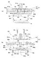
図2及び図3(a),(b)に示すように、吸着ノズル22は、シャフト部材21の下端に取り付けられるノズル基部41及びノズル基部41に着脱自在に取り付けられるノズル先端部42から成る。
As shown in FIGS. 2, 3 (a), and 3 (b), the
図4(a),(b)及び図5(a),(b)において、ノズル基部41は、上面に上方に突出する円錐台形状部51a及びその下端に設けられた円盤形状部51bを備えたノズル基部上半体51と、ノズル基部上半体51の円盤形状部51bと上下に合致する大きさの円盤形状部52a及びその下端に設けられた矩形の平板形状部52bを備えたノズル基部下半体52から成る。
4 (a), 4 (b) and 5 (a), 5 (b), the
図5(a),(b)において、ノズル基部上半体51の内部には円錐台形状部51aを上下方向に貫通して延びたノズル基部上半体内真空路53が設けられており、ノズル基部下半体52の内部にはノズル基部上半体内真空路53と連通して上下方向に貫通して延びたノズル基部下半体内真空路54が設けられている。
5A and 5B, the nozzle base
図3(a),(b)、図4(a),(b)及び図5(a),(b)において、ノズル先端部42は、上面がノズル基部下半体52の平板形状部52bの下面と接触する直方体形状のノズル先端部ベース部61及びノズル先端部ベース部61の下面から下方に突出して延びて吸着対象の枠状部品5と接触するノズル先端部接触部62を有して成る。
3 (a), 3 (b), 4 (a), 4 (b) and 5 (a), 5 (b), the
図3(a),(b)において、ノズル先端部接触部62の外形形状は、吸着対象とする枠状部品5の外形形状とほぼ同じ形状に形成されており、ノズル先端部接触部62の枠状部品5の枠内の部分に相当する領域R(図5(a))には下方に開口する凹形状に肉抜きされた肉抜き部(空洞部)62aが設けられている(図5(a),(b)も参照)。
3A and 3B, the outer shape of the nozzle
図5(a),(b)において、ノズル先端部42の内部には、ノズル基部下半体52の内部に設けられたノズル基部下半体内真空路54と連通するノズル先端部内真空路63が設けられている。このノズル先端部内真空路63は分岐してノズル先端部接触部62内を延び、ノズル先端部接触部62の下面(下端)に開口して複数の吸着孔64を形成している(図3も参照)。
5 (a) and 5 (b), the nozzle tip
図4(a),(b)及び図5(a),(b)において、ノズル先端部42は、複数の取り付け螺子70によりノズル基部41に着脱自在に取り付けられる。すなわち、ノズル基部上半体51、ノズル基部下半体52及びノズル先端部42(ノズル先端部ベース部61)にはそれぞれ複数の螺子取り付け孔51h,52h,42h(ノズル基部上半体51に設けられた螺子取り付け孔51hとノズル基部下半体52に設けられた螺子取り付け孔52hは取り付け螺子70を挿通させる貫通孔、ノズル先端部42に設けられた螺子取り付け孔42hは取り付け螺子70が螺入される螺子孔)が設けられており、ノズル基部上半体51に設けられた螺子取り付け孔51h及びノズル基部下半体52に設けられた螺子取り付け孔52hに挿通させた取り付け螺子70をノズル先端部42に設けられた螺子取り付け孔42hに螺入することで、ノズル基部上半体51、ノズル基部下半体52及びノズル先端部42を一体に結合してノズル基部41(ノズル基部上半体51、ノズル基部下半体52)にノズル先端部42を取り付けることができる。
4A, 4B, 5A, and 5B, the
なお、図4(a),(b)及び図5(a),(b)に示すように、取り付け螺子70は頭部の上面が平らな皿螺子であるので、取り付け螺子70によりノズル先端部42をノズル基部41に取り付けた状態において、ノズル基部41の円盤形状部51bの上面は平らな状態となる。
As shown in FIGS. 4A and 4B and FIGS. 5A and 5B, the
図4(a),(b)及び図5(a),(b)において、ノズル基部下半体52には上下方向に延びた複数(ここでは2つ)の位置決めピン71が設けられている。各位置決めピン71はノズル基部下半体52を厚さ方向に貫通して延びており、その上端部はノズル基部下半体52の上面(円盤形状部52aの上面)から上方に突出し、下端部はノズル基部下半体52の下面(平板形状部52bの下面)から下方に突出している。一方、ノズル基部上半体51にはノズル基部下半体52に設けられた複数の位置決めピン71それぞれの上端部が挿入される複数のノズル基部上半体側ピン挿入孔51jが下方に開口して設けられており、ノズル先端部42のノズル基部41との接触面42s(ノズル先端部ベース部61の上面)には、ノズル基部下半体52に設けられた複数の位置決めピン71それぞれの下端部が挿入される複数のノズル先端部側ピン挿入孔42jが上方に開口して設けられている。
4A, 4B, and 5A, 5B, the nozzle base
ノズル先端部42をノズル基部41に取り付けるときには、ノズル基部下半体52に設けられた複数の位置決めピン71の上端部がノズル基部上半体51の複数のノズル基部上半体側ピン挿入孔51jに挿入されるようにし、また、ノズル基部下半体52に設けられた複数の位置決めピン71の下端部がノズル先端部ベース部61の複数のノズル先端部側ピン挿入孔42jに挿入されるようにしたうえで、前述のように、複数の取り付け螺子70によって、ノズル基部41にノズル先端部42を取り付ける(図3(a),(b))。
When the
このように、上記ノズル先端部42のノズル基部41への取り付けでは、ノズル基部41から下方に突出して延びた複数の位置決めピン71の端部(下端部)がノズル先端部42(ノズル先端部ベース部61)のノズル基部41との接触面42sに開口して設けられた複数のノズル先端部側ピン挿入孔42jに挿入されることによってノズル基部41に対するノズル先端部42の位置決めがなされようになっているので、ノズル先端部42はノズル基部41にしっかりと位置決めされた状態でノズル基部41に取り付けられる。
As described above, when the
ここで、複数の位置決めピン71、ノズル先端部側ピン挿入孔42j、螺子取り付け孔52h及び螺子取り付け孔42hの配置は、複数の位置決めピン71がノズル先端部側ピン挿入孔42jに正規の組み合わせで挿入された場合にのみ螺子取り付け孔52hと螺子取り付け孔42hが上下に一致するようになっている。すなわち、ノズル先端部42は、ノズル基部41側の複数の位置決めピン71が複数のノズル先端部側ピン挿入孔42jに正規の組み合わせで挿入された場合にのみノズル基部41に取り付けることができるようになっている。このため、ノズル先端部42が誤った向きにノズル基部41に取り付けられるおそれがなく、特に、ノズル先端部接触部62の外形が非対称に形成される場合には有効である。
Here, the plurality of positioning pins 71, the nozzle tip portion side
また、上記のようにノズル基部41にノズル先端部42が取り付けられることによって、ノズル基部上半体内真空路53、ノズル基部下半体内真空路54及びノズル先端部内真空路63が互いに連通した状態となる(図5(a))。
In addition, by attaching the
ここで、図4(b)から分かるように、ノズル先端部42のノズル基部41との接触面42sにおけるノズル先端部内真空路63の周りの肉厚(ノズル先端部内真空路63の半径方向の肉厚)は非常に厚くなっていることから、ノズル先端部42の接触面42sとノズル基部41の平板形状部52bの下面との密着性は非常に高い。このためノズル先端部42の接触面42sとノズル基部41の平板形状部52bの下面との間に、ノズル基部下半体内真空路54とノズル先端部内真空路63とを空気漏れさせることなく連通させるためのパッキンは不要である。
Here, as can be seen from FIG. 4B, the thickness around the nozzle tip
図2に示すように、吸着ノズル22は、ノズル基部上半体51に設けられた円錐台形状部51aがシャフト部材21の下端に下方から挿入されてシャフト部材21に取り付けられる。吸着ノズル22がシャフト部材21に取り付けられた状態では、吸着ノズル22のノズル基部上半体内真空路53がシャフト部材21内を延びる装着ヘッド側真空圧供給管路14a(図2)と連通するので、吸着機構32から吸着ノズル22の下端の複数の吸着孔64を通じた真空吸引動作が可能となる。
As shown in FIG. 2, the
なお、前述のように、取り付け螺子70は頭部の上面が平らな皿螺子であって、取り付け螺子70によりノズル先端部42をノズル基部41に取り付けた状態において、ノズル基部41の円盤形状部51bの上面は平らな状態となるので、ノズル基部41をシャフト部材21に取り付ける際には、シャフト部材21の下端をノズル基部41の円盤形状部51bの上面に当接させることができ、吸着ノズル22を安定した状態でシャフト部材21に取り付けることができる。
As described above, the mounting
図6(a),(b)に示すように、枠状部品5は、基板2の電極3上に既に装着されている電子部品4(電子部品群)の周囲を取り囲むように基板2上に装着される。本実施の形態における枠状部品5では、上面に3つの吸着指定箇所P1,P2,P3が設定されており(図2も参照)、ノズル先端部42の下端の吸着孔64は上記3つの吸着指定箇所P1,P2,P3に対応した位置に設けられている(図3(a))。
As shown in FIGS. 6A and 6B, the frame-shaped
次に、本実施の形態における部品実装装置1による枠状部品5の基板2への装着作業について説明する。
Next, the mounting operation of the frame-shaped
部品実装装置1による枠状部品5の基板2への装着作業では、部品実装装置1の制御装置17は先ず、基板搬送コンベア11を作動させ、部品実装装置1の上流工程側の装置から送られてきた電子部品4の装着済みの基板2を受け取って搬送することにより、基板2を所定の作業位置に位置決めする。制御装置17は、基板2を作業位置に位置決めしたら、装着ヘッド移動機構13の作動制御を行って装着ヘッド14を移動させ、基板カメラ15に基板2上の一対の基板マーク2mの撮像を行わせる。制御装置17は、一対の基板マーク2mの画像データが得られたら、その基板マーク2mの画像認識を行って基板2の基準位置からの位置ずれを求める。
In the mounting operation of the frame-shaped
制御装置17は、基板2の基準位置からの位置ずれを求めたら、装着ヘッド移動機構13の作動制御を行って装着ヘッド14をトレイ12の上方に位置させるとともに、シャフト部材駆動機構31及び吸着機構32の作動制御を行って装着ヘッド14が備える吸着ノズル22に枠状部品5を吸着させる。この枠状部品5の吸着では、吸着ノズル22が備えるノズル先端部接触部62の外形をトレイ12上の枠状部品5の外形に合わせるようにして吸着ノズル22の下端を枠状部品5の上面に接触させたうえで、吸着機構32を作動させて、吸着ノズル22の下端の複数の吸着孔64から真空吸引を行う。これによりトレイ12内の枠状部品5は吸着ノズル22を介して装着ヘッド14に吸着される。
When the
制御装置17は、吸着ノズル22を介して装着ヘッド14に枠状部品5を吸着させたら、装着ヘッド14を移動させて枠状部品5が部品カメラ16の上方を通過するように装着ヘッド14を移動させる。そして、部品カメラ16に枠状部品5の撮像を行わせ(図7)、得られた画像データに基づく画像認識を行って、吸着ノズル22に対する枠状部品5の位置ずれを算出する。
When the
この部品カメラ16による枠状部品5の撮像及び画像認識工程では、吸着ノズル22の枠状部品5と接触するノズル先端部接触部62の外形形状が枠状部品5の外形とほぼ等しい形状に形成されるとともに、ノズル先端部接触部62の枠状部品5の枠内の部分に相当する領域Rが下方に開口する凹形状に肉抜きされており、部品カメラ16による枠状部品5の撮像時の焦点F(図7)は枠状部品5の下面の高さの位置に設定されていることから、吸着ノズル22を用いて吸着した枠状部品5を下方から撮像して得られた画像では、ノズル先端部42の枠状部品5の枠内の部分に相当する領域Rの下面42Rは焦点Fの位置よりも高くてぼやけることになる。このため、吸着ノズル22の上記下面42Rに傷や異物が付いていたとしてもその部分が明るく映ずるようなことはなく、枠状部品5の画像認識の際に吸着ノズル22の一部が枠状部品5の一部であると誤認識されることがない。
In the imaging and image recognition process of the frame-shaped
制御装置17は、枠状部品5の撮像及び画像認識を行って吸着ノズル22に対する枠状部品5の位置ずれを算出したら、装着ヘッド移動機構13の作動制御を行って、装着ヘッド14を基板2の上方に位置させる。そして、制御装置17はシャフト部材21を装着ヘッド14に対して下動させて枠状部品5を下降させ(図6(a)中に示す矢印A)、枠状部品5が基板2に接触したところで真空吸着を解除して枠状部品5を基板2上に装着する(図6(b))。
When the
制御装置17は、枠状部品5の基板2への装着作業が終了したら装着ヘッド14に対してシャフト部材21を上動させ、次の枠状部品5の吸着及び基板2への装着を行う。基板2に装着すべき全ての枠状部品5を基板2上に装着したら、制御装置17が基板搬送コンベア11を作動させて、基板2を部品実装装置1の下流工程側の装置に搬出する。
When the mounting operation of the frame-shaped
以上説明したように、本実施の形態における吸着ノズル22(及び吸着ノズル22を備えた部品実装装置1)では、ノズル基部41から突出して延びた複数のピン(位置決めピン71)の端部がノズル先端部42に設けられた複数のピン挿入孔(ノズル先端部側ピン挿入孔42j)に挿入されることによってノズル基部41に対するノズル先端部42の位置決めがなされようになっており、ノズル先端部42はノズル基部41にしっかりと位置決めされた状態でノズル基部41に取り付けられるので、ノズル基部41に対するノズル先端部42の位置は常に一定し、吸着の対象とする部品と吸着ノズル22との接触面積が小さい場合であってもリークによる部品の吸着ミスを生じにくい。
As described above, in the suction nozzle 22 (and the
なお、上述の実施の形態では、吸着ノズル22によって吸着される対象部品が枠状に形成された枠状部品5から成っていたが、吸着ノズル22の吸着対象となる部品はこのような枠状部品に限られず、他の部品であってもよい。特に、微小部品であれば、部品が枠状部品である場合と同様に、吸着の対象とする部品と吸着ノズル22との接触面積が小さくなるので、本実施の形態における吸着ノズル22を用いる効果は大きなものとなる。
In the above-described embodiment, the target component sucked by the
吸着対象とする部品と吸着ノズルとの接触面積が小さい場合であってもリークによる部品の吸着ミスを生じにくい構成の吸着ノズル及び部品実装装置を提供する。 Provided is a suction nozzle and a component mounting apparatus having a configuration in which even if the contact area between a component to be suctioned and a suction nozzle is small, a component suction error due to leakage is unlikely to occur.
1 部品実装装置
2 基板
5 枠状部品(部品)
14 装着ヘッド
22 吸着ノズル
41 ノズル基部
42 ノズル先端部
42s 接触面
42j ノズル先端部側ピン挿入穴(ピン挿入孔)
64 吸着孔
70 取り付け螺子(螺子)
71 位置決めピン(ピン)
1
14 Mounting
64
71 Positioning pin (pin)
Claims (5)
装着ヘッドに取り付けられるノズル基部と、
ノズル基部に着脱自在に取り付けられ、下端に前記吸着孔を有したノズル先端部とを有し、
ノズル先端部は、ノズル基部から下方に突出して設けられた複数のピンがノズル基部との接触面に開口して設けられた複数のピン挿入孔に挿入されることによってノズル基部に対する位置決めがなされることを特徴とする吸着ノズル。 A suction nozzle that is attached to the mounting head provided in the component mounting apparatus and sucks the component by vacuum suction from the suction hole at the lower end,
A nozzle base attached to the mounting head;
A nozzle base that is detachably attached to the nozzle base and has the suction hole at the lower end;
The nozzle tip portion is positioned with respect to the nozzle base portion by inserting a plurality of pins provided projecting downward from the nozzle base portion into a plurality of pin insertion holes provided on the contact surface with the nozzle base portion. A suction nozzle characterized by that.
Priority Applications (2)
| Application Number | Priority Date | Filing Date | Title |
|---|---|---|---|
| JP2012009875A JP5838301B2 (en) | 2012-01-20 | 2012-01-20 | Suction nozzle and component mounting device |
| CN 201220656693 CN203279461U (en) | 2012-01-20 | 2012-12-03 | Suction nozzle and element installation device |
Applications Claiming Priority (1)
| Application Number | Priority Date | Filing Date | Title |
|---|---|---|---|
| JP2012009875A JP5838301B2 (en) | 2012-01-20 | 2012-01-20 | Suction nozzle and component mounting device |
Publications (2)
| Publication Number | Publication Date |
|---|---|
| JP2013146834A true JP2013146834A (en) | 2013-08-01 |
| JP5838301B2 JP5838301B2 (en) | 2016-01-06 |
Family
ID=49044884
Family Applications (1)
| Application Number | Title | Priority Date | Filing Date |
|---|---|---|---|
| JP2012009875A Active JP5838301B2 (en) | 2012-01-20 | 2012-01-20 | Suction nozzle and component mounting device |
Country Status (2)
| Country | Link |
|---|---|
| JP (1) | JP5838301B2 (en) |
| CN (1) | CN203279461U (en) |
Cited By (1)
| Publication number | Priority date | Publication date | Assignee | Title |
|---|---|---|---|---|
| CN106393158A (en) * | 2016-11-29 | 2017-02-15 | 苏州阿里夫电子科技有限公司 | Novel rivet suction nozzle |
Families Citing this family (3)
| Publication number | Priority date | Publication date | Assignee | Title |
|---|---|---|---|---|
| CN106664821B (en) * | 2014-08-06 | 2019-05-31 | 株式会社富士 | Device is arranged in suction nozzle platform |
| CN106003109A (en) * | 2016-07-21 | 2016-10-12 | 英杰精密模塑股份有限公司 | Manipulator clamp holder assembling structure |
| CN111496833B (en) * | 2020-04-22 | 2022-02-01 | Oppo(重庆)智能科技有限公司 | Suction nozzle and suction device |
Citations (6)
| Publication number | Priority date | Publication date | Assignee | Title |
|---|---|---|---|---|
| JPS61131881A (en) * | 1984-11-28 | 1986-06-19 | 日立金属株式会社 | Suction type take-up device |
| JPH01108999U (en) * | 1988-01-18 | 1989-07-24 | ||
| JPH04192554A (en) * | 1990-11-27 | 1992-07-10 | Hitachi Ltd | Method and apparatus for assembly of electronic component |
| JPH0711291U (en) * | 1992-01-30 | 1995-02-21 | しなのポリマー株式会社 | Transport hand |
| JP2006351980A (en) * | 2005-06-20 | 2006-12-28 | Matsushita Electric Ind Co Ltd | Thermo-compression tool for electronic component, and apparatus and method for mounting electronic component |
| JP2007283465A (en) * | 2006-04-20 | 2007-11-01 | Matsushita Electric Ind Co Ltd | Suction nozzle |
-
2012
- 2012-01-20 JP JP2012009875A patent/JP5838301B2/en active Active
- 2012-12-03 CN CN 201220656693 patent/CN203279461U/en not_active Expired - Lifetime
Patent Citations (6)
| Publication number | Priority date | Publication date | Assignee | Title |
|---|---|---|---|---|
| JPS61131881A (en) * | 1984-11-28 | 1986-06-19 | 日立金属株式会社 | Suction type take-up device |
| JPH01108999U (en) * | 1988-01-18 | 1989-07-24 | ||
| JPH04192554A (en) * | 1990-11-27 | 1992-07-10 | Hitachi Ltd | Method and apparatus for assembly of electronic component |
| JPH0711291U (en) * | 1992-01-30 | 1995-02-21 | しなのポリマー株式会社 | Transport hand |
| JP2006351980A (en) * | 2005-06-20 | 2006-12-28 | Matsushita Electric Ind Co Ltd | Thermo-compression tool for electronic component, and apparatus and method for mounting electronic component |
| JP2007283465A (en) * | 2006-04-20 | 2007-11-01 | Matsushita Electric Ind Co Ltd | Suction nozzle |
Cited By (1)
| Publication number | Priority date | Publication date | Assignee | Title |
|---|---|---|---|---|
| CN106393158A (en) * | 2016-11-29 | 2017-02-15 | 苏州阿里夫电子科技有限公司 | Novel rivet suction nozzle |
Also Published As
| Publication number | Publication date |
|---|---|
| JP5838301B2 (en) | 2016-01-06 |
| CN203279461U (en) | 2013-11-06 |
Similar Documents
| Publication | Publication Date | Title |
|---|---|---|
| JP2013222771A (en) | Holding nozzle and electronic component mounting apparatus | |
| JP5838301B2 (en) | Suction nozzle and component mounting device | |
| WO2013080408A1 (en) | Component mounting method and component mounting system | |
| TW201343023A (en) | Alignment device and method to align plates for electronic circuits, and apparatus for processing a substrate | |
| JP6131023B2 (en) | Nozzle replacement mechanism and electronic component mounting apparatus | |
| JP6603475B2 (en) | Substrate transport device and electronic component mounting device | |
| JP2014143365A (en) | Electronic component mounting device and electronic component mounting method | |
| JP4760752B2 (en) | Component mounting device and mounting position accuracy measuring method in component mounting device | |
| JP6047239B2 (en) | Component suction nozzle and component mounting device | |
| JP5824641B2 (en) | Suction nozzle and component mounting device | |
| JP6767625B2 (en) | Parts mounting device | |
| JP6666692B2 (en) | Component mounting machine, component suction method | |
| JP2013219131A (en) | Attachment method of suction nozzle, component mounting method, and component mounting device | |
| JP5895127B2 (en) | Suction tool and component mounting device | |
| JP6147928B2 (en) | Component suction nozzle, component transport device, and component mounting device | |
| JP5786136B2 (en) | Component suction nozzle and component mounting apparatus | |
| WO2016125245A1 (en) | Supplied component transfer device | |
| JP5895128B2 (en) | Suction tool and component mounting device | |
| JP5861036B2 (en) | Adsorption nozzle orientation determination method and component mounting apparatus | |
| KR102062278B1 (en) | Chip mounter | |
| JP6738996B2 (en) | Component mounting method | |
| JP2013229477A (en) | Component mounting method and component mounting apparatus | |
| JP2019054077A (en) | Component mounting apparatus and component mounting method | |
| JP6861335B2 (en) | Component mounting device and component mounting method | |
| JP2013004758A (en) | Apparatus for loading spherical body, method for loading spherical body, substrate having spherical body loaded thereon and substrate having electronic component loaded thereon |
Legal Events
| Date | Code | Title | Description |
|---|---|---|---|
| A621 | Written request for application examination |
Free format text: JAPANESE INTERMEDIATE CODE: A621 Effective date: 20140613 |
|
| RD01 | Notification of change of attorney |
Free format text: JAPANESE INTERMEDIATE CODE: A7421 Effective date: 20140714 |
|
| A711 | Notification of change in applicant |
Free format text: JAPANESE INTERMEDIATE CODE: A711 Effective date: 20141007 |
|
| A871 | Explanation of circumstances concerning accelerated examination |
Free format text: JAPANESE INTERMEDIATE CODE: A871 Effective date: 20141105 |
|
| A975 | Report on accelerated examination |
Free format text: JAPANESE INTERMEDIATE CODE: A971005 Effective date: 20150109 |
|
| A131 | Notification of reasons for refusal |
Free format text: JAPANESE INTERMEDIATE CODE: A131 Effective date: 20150120 |
|
| A521 | Written amendment |
Free format text: JAPANESE INTERMEDIATE CODE: A523 Effective date: 20150227 |
|
| TRDD | Decision of grant or rejection written | ||
| A01 | Written decision to grant a patent or to grant a registration (utility model) |
Free format text: JAPANESE INTERMEDIATE CODE: A01 Effective date: 20150526 |
|
| A61 | First payment of annual fees (during grant procedure) |
Free format text: JAPANESE INTERMEDIATE CODE: A61 Effective date: 20150608 |
|
| R151 | Written notification of patent or utility model registration |
Ref document number: 5838301 Country of ref document: JP Free format text: JAPANESE INTERMEDIATE CODE: R151 |