JP2013144159A - Sterilization method and apparatus - Google Patents
Sterilization method and apparatus Download PDFInfo
- Publication number
- JP2013144159A JP2013144159A JP2013083142A JP2013083142A JP2013144159A JP 2013144159 A JP2013144159 A JP 2013144159A JP 2013083142 A JP2013083142 A JP 2013083142A JP 2013083142 A JP2013083142 A JP 2013083142A JP 2013144159 A JP2013144159 A JP 2013144159A
- Authority
- JP
- Japan
- Prior art keywords
- hydrogen peroxide
- sterilization
- ozone
- chamber
- oxygen
- Prior art date
- Legal status (The legal status is an assumption and is not a legal conclusion. Google has not performed a legal analysis and makes no representation as to the accuracy of the status listed.)
- Granted
Links
Images


Classifications
-
- A—HUMAN NECESSITIES
- A61—MEDICAL OR VETERINARY SCIENCE; HYGIENE
- A61L—METHODS OR APPARATUS FOR STERILISING MATERIALS OR OBJECTS IN GENERAL; DISINFECTION, STERILISATION OR DEODORISATION OF AIR; CHEMICAL ASPECTS OF BANDAGES, DRESSINGS, ABSORBENT PADS OR SURGICAL ARTICLES; MATERIALS FOR BANDAGES, DRESSINGS, ABSORBENT PADS OR SURGICAL ARTICLES
- A61L2/00—Methods or apparatus for disinfecting or sterilising materials or objects other than foodstuffs or contact lenses; Accessories therefor
- A61L2/16—Methods or apparatus for disinfecting or sterilising materials or objects other than foodstuffs or contact lenses; Accessories therefor using chemical substances
- A61L2/20—Gaseous substances, e.g. vapours
- A61L2/202—Ozone
-
- A—HUMAN NECESSITIES
- A61—MEDICAL OR VETERINARY SCIENCE; HYGIENE
- A61L—METHODS OR APPARATUS FOR STERILISING MATERIALS OR OBJECTS IN GENERAL; DISINFECTION, STERILISATION OR DEODORISATION OF AIR; CHEMICAL ASPECTS OF BANDAGES, DRESSINGS, ABSORBENT PADS OR SURGICAL ARTICLES; MATERIALS FOR BANDAGES, DRESSINGS, ABSORBENT PADS OR SURGICAL ARTICLES
- A61L2/00—Methods or apparatus for disinfecting or sterilising materials or objects other than foodstuffs or contact lenses; Accessories therefor
- A61L2/16—Methods or apparatus for disinfecting or sterilising materials or objects other than foodstuffs or contact lenses; Accessories therefor using chemical substances
- A61L2/20—Gaseous substances, e.g. vapours
- A61L2/208—Hydrogen peroxide
-
- A—HUMAN NECESSITIES
- A61—MEDICAL OR VETERINARY SCIENCE; HYGIENE
- A61L—METHODS OR APPARATUS FOR STERILISING MATERIALS OR OBJECTS IN GENERAL; DISINFECTION, STERILISATION OR DEODORISATION OF AIR; CHEMICAL ASPECTS OF BANDAGES, DRESSINGS, ABSORBENT PADS OR SURGICAL ARTICLES; MATERIALS FOR BANDAGES, DRESSINGS, ABSORBENT PADS OR SURGICAL ARTICLES
- A61L2/00—Methods or apparatus for disinfecting or sterilising materials or objects other than foodstuffs or contact lenses; Accessories therefor
- A61L2/24—Apparatus using programmed or automatic operation
-
- B—PERFORMING OPERATIONS; TRANSPORTING
- B65—CONVEYING; PACKING; STORING; HANDLING THIN OR FILAMENTARY MATERIAL
- B65D—CONTAINERS FOR STORAGE OR TRANSPORT OF ARTICLES OR MATERIALS, e.g. BAGS, BARRELS, BOTTLES, BOXES, CANS, CARTONS, CRATES, DRUMS, JARS, TANKS, HOPPERS, FORWARDING CONTAINERS; ACCESSORIES, CLOSURES, OR FITTINGS THEREFOR; PACKAGING ELEMENTS; PACKAGES
- B65D23/00—Details of bottles or jars not otherwise provided for
- B65D23/001—Supporting means fixed to the container
-
- A—HUMAN NECESSITIES
- A61—MEDICAL OR VETERINARY SCIENCE; HYGIENE
- A61L—METHODS OR APPARATUS FOR STERILISING MATERIALS OR OBJECTS IN GENERAL; DISINFECTION, STERILISATION OR DEODORISATION OF AIR; CHEMICAL ASPECTS OF BANDAGES, DRESSINGS, ABSORBENT PADS OR SURGICAL ARTICLES; MATERIALS FOR BANDAGES, DRESSINGS, ABSORBENT PADS OR SURGICAL ARTICLES
- A61L2202/00—Aspects relating to methods or apparatus for disinfecting or sterilising materials or objects
- A61L2202/10—Apparatus features
- A61L2202/12—Apparatus for isolating biocidal substances from the environment
- A61L2202/122—Chambers for sterilisation
-
- A—HUMAN NECESSITIES
- A61—MEDICAL OR VETERINARY SCIENCE; HYGIENE
- A61L—METHODS OR APPARATUS FOR STERILISING MATERIALS OR OBJECTS IN GENERAL; DISINFECTION, STERILISATION OR DEODORISATION OF AIR; CHEMICAL ASPECTS OF BANDAGES, DRESSINGS, ABSORBENT PADS OR SURGICAL ARTICLES; MATERIALS FOR BANDAGES, DRESSINGS, ABSORBENT PADS OR SURGICAL ARTICLES
- A61L2202/00—Aspects relating to methods or apparatus for disinfecting or sterilising materials or objects
- A61L2202/10—Apparatus features
- A61L2202/13—Biocide decomposition means, e.g. catalysts, sorbents
-
- A—HUMAN NECESSITIES
- A61—MEDICAL OR VETERINARY SCIENCE; HYGIENE
- A61L—METHODS OR APPARATUS FOR STERILISING MATERIALS OR OBJECTS IN GENERAL; DISINFECTION, STERILISATION OR DEODORISATION OF AIR; CHEMICAL ASPECTS OF BANDAGES, DRESSINGS, ABSORBENT PADS OR SURGICAL ARTICLES; MATERIALS FOR BANDAGES, DRESSINGS, ABSORBENT PADS OR SURGICAL ARTICLES
- A61L2202/00—Aspects relating to methods or apparatus for disinfecting or sterilising materials or objects
- A61L2202/10—Apparatus features
- A61L2202/14—Means for controlling sterilisation processes, data processing, presentation and storage means, e.g. sensors, controllers, programs
-
- A—HUMAN NECESSITIES
- A61—MEDICAL OR VETERINARY SCIENCE; HYGIENE
- A61L—METHODS OR APPARATUS FOR STERILISING MATERIALS OR OBJECTS IN GENERAL; DISINFECTION, STERILISATION OR DEODORISATION OF AIR; CHEMICAL ASPECTS OF BANDAGES, DRESSINGS, ABSORBENT PADS OR SURGICAL ARTICLES; MATERIALS FOR BANDAGES, DRESSINGS, ABSORBENT PADS OR SURGICAL ARTICLES
- A61L2202/00—Aspects relating to methods or apparatus for disinfecting or sterilising materials or objects
- A61L2202/20—Targets to be treated
- A61L2202/24—Medical instruments, e.g. endoscopes, catheters, sharps
Abstract
Description
本発明は、一般的に、滅菌方法及び装置に関する。さらに特に、本発明は、真空下でガス状の殺生物剤を使用する滅菌プロセスに関する。 The present invention relates generally to sterilization methods and devices. More particularly, the invention relates to a sterilization process using a gaseous biocide under vacuum.
滅菌は、栄養胞子状態又は休眠胞子状態における、あらゆるウイルス、バクテリア、菌類、又は、他の微生物の破壊であり、及び、バクテリアの濃度の10-6の減少によって定義される。医療器具のための従来の滅菌処理手順が、(蒸気又は乾燥熱ユニットのような)高温度、又は、(酸化エチレンガス、過酸化水素、又は、オゾンのような)化学物質を含む。 Sterilization is the destruction of any virus, bacteria, fungi, or other microorganism in a vegetative or dormant spore state and is defined by a 10 -6 decrease in the concentration of bacteria. Conventional sterilization procedures for medical devices include high temperatures (such as steam or dry heat units) or chemicals (such as ethylene oxide gas, hydrogen peroxide, or ozone).
ガス状の滅菌剤を使用する滅菌方法及び装置が公知である。滅菌剤として過酸化水素を使用する滅菌装置が広く使用されている。過酸化水素は、一般的に水溶液として供給され、及び、滅菌装置の滅菌チャンバに注入する前に、その溶液の加熱によって、又は、滅菌チャンバに真空を加えることによって、又は、その両方によって蒸発させられる。この溶液の蒸発の後に、滅菌チャンバ内の滅菌雰囲気が水蒸気と過酸化水素ガスとを含む。滅菌が進行するにつれて水蒸気が滅菌チャンバ内の物品上で凝縮する傾向があるということが、このプロセスの欠点である。滅菌される物品上の結果的に生じる凝縮水の層が、過酸化水素の滅菌作用に悪影響を与える。多数の装置及びプロセスの変型がこの問題に対処するために開発されてきたが、これらの全ては、滅菌プロセス中の滅菌雰囲気における相対湿度を制限することを目的としている。しかし、これらの変型は、必ず運転コスト及び/又は滅菌サイクル時間を増大させる。 Sterilization methods and devices that use gaseous sterilants are known. Sterilizers that use hydrogen peroxide as a sterilant are widely used. Hydrogen peroxide is typically supplied as an aqueous solution and evaporated by heating the solution and / or applying a vacuum to the sterilization chamber before being injected into the sterilization chamber of the sterilizer. It is done. After evaporation of this solution, the sterilizing atmosphere in the sterilization chamber contains water vapor and hydrogen peroxide gas. It is a drawback of this process that water vapor tends to condense on the articles in the sterilization chamber as sterilization proceeds. The resulting layer of condensed water on the article to be sterilized adversely affects the sterilization effect of hydrogen peroxide. A number of device and process variants have been developed to address this problem, all of which are aimed at limiting the relative humidity in the sterilizing atmosphere during the sterilization process. However, these variations necessarily increase operating costs and / or sterilization cycle times.
過酸化水素ガスとオゾンガスの両方を使用する滅菌プロセスが使用されてきたが、このプロセスでは、特に、胃カメラと大腸内視鏡のような長い内部管腔を有する物品の滅菌に関して、及び、サイクル時間と滅菌コストに関して、不十分な結果しか得られていない。オゾンに基づく滅菌プロセスは、長い内部管腔を有する物品に関しては適切であるが、材料の適合性が問題となる。過酸化水素に基づく滅菌プロセスは、一般的に、長い内部管腔の滅菌に関しては不十分である。滅菌される物品上の望ましくない過酸化水素の凝縮水が、滅菌効率を減じる。 A sterilization process using both hydrogen peroxide gas and ozone gas has been used, particularly with respect to sterilization of articles with long internal lumens such as gastrocameras and colonoscopy and cycles. Insufficient results have been obtained in terms of time and sterilization costs. Ozone-based sterilization processes are appropriate for articles with long internal lumens, but material compatibility is a problem. Hydrogen peroxide-based sterilization processes are generally inadequate for sterilization of long internal lumens. Undesirable hydrogen peroxide condensate on the article to be sterilized reduces sterilization efficiency.
したがって、ガス状の滅菌剤を使用する公知の滅菌プロセスの欠点の少なくとも1つに対処する方法と装置が求められている。 Accordingly, there is a need for a method and apparatus that addresses at least one of the disadvantages of known sterilization processes that use gaseous sterilants.
本発明の目的が、ガス状の滅菌剤を使用する従来の滅菌プロセスの少なくとも1つの欠点を回避又は緩和することである。 It is an object of the present invention to avoid or mitigate at least one disadvantage of conventional sterilization processes that use gaseous sterilants.
第1の側面において、予め選択された温度での滅菌チャンバ内の過酸化水素の望ましくない凝縮を抑制する方法を提供する。この方法は、前記予め選択された温度で過酸化水素が沸騰する圧力よりも低い真空圧に前記滅菌チャンバを維持する段階と、過酸化水素の連続パルスを蒸発させる段階と、前記蒸発した過酸化水素を前記チャンバ内に注入し、これによって過酸化水素の各パルスの体積が75μL未満である段階とを含む。 In a first aspect, a method is provided for inhibiting undesired condensation of hydrogen peroxide in a sterilization chamber at a preselected temperature. The method includes maintaining the sterilization chamber at a vacuum pressure lower than a pressure at which hydrogen peroxide boils at the preselected temperature, evaporating a continuous pulse of hydrogen peroxide, and evaporating the peroxide. Injecting hydrogen into the chamber, whereby the volume of each pulse of hydrogen peroxide is less than 75 μL.
第2の側面において、各パルスの体積は35μL未満である。 In the second aspect, the volume of each pulse is less than 35 μL.
第3の側面において、各パルスの体積は20μL未満である。 In the third aspect, the volume of each pulse is less than 20 μL.
本発明の他の側面と特徴とが、添付図面に関連付けて本発明の特定の実施形態の後述の説明を検討することによって、当業者に明らかになるだろう。 Other aspects and features of the present invention will become apparent to those of ordinary skill in the art upon review of the following description of specific embodiments of the invention in conjunction with the accompanying drawings.
以下では、本発明の実施形態を、添付図面を参照しながら、単なる具体例の形で説明する。 In the following, embodiments of the present invention will be described in the form of specific examples only with reference to the accompanying drawings.
本発明は、一般的に、蒸発過酸化水素を逐次的に添加することによる、ガス状滅菌雰囲気の中での物品の滅菌のための方法、特に、予め選択された温度での滅菌チャンバ内の過酸化水素の望ましくない凝縮を抑制する方法を提供する。この方法は、予め選択された温度で過酸化水素が沸騰する圧力よりも低い真空圧に滅菌チャンバを維持する段階と、過酸化水素の連続パルスを蒸発させる段階と、蒸発した過酸化水素をチャンバ内にパルスで注入し、各パルスの体積が、予め選択された温度での過酸化水素の望ましくない凝縮を抑制するように選択される。 The present invention generally relates to a method for the sterilization of articles in a gaseous sterilization atmosphere by the sequential addition of evaporated hydrogen peroxide, in particular in a sterilization chamber at a preselected temperature. A method is provided for inhibiting undesirable condensation of hydrogen peroxide. The method includes maintaining the sterilization chamber at a vacuum pressure lower than the pressure at which the hydrogen peroxide boils at a preselected temperature, evaporating a continuous pulse of hydrogen peroxide, and evaporating the evaporated hydrogen peroxide into the chamber. Injected in pulses, the volume of each pulse is selected to suppress undesired condensation of hydrogen peroxide at a preselected temperature.
以下にさらに説明するように、滅菌チャンバ内に注入される蒸発過酸化水素溶液が、滅菌すべき物品上で凝縮する。しかしながら、過酸化水素が凝縮中に気相から除去されるので、過酸化水素の凝縮水が長い内部管腔の滅菌作用に悪影響を与える。したがって、過酸化水素が長い内部管腔を貫通するように、過酸化水素が、可能な限り長く気相で維持されなければならず、過酸化水素の注入中に凝縮が避けられなければならない。これは、本発明により、個々の過酸化水素の注入パルスの体積を制御することによって実現される。一つの実施形態では、過酸化水素の各パルスの体積が75μL未満である。別の実施形態では、過酸化水素の各パルスの体積は35μL未満である。さらなる実施形態では、過酸化水素の各パルスの体積は20μL未満である。 As described further below, the evaporated hydrogen peroxide solution injected into the sterilization chamber condenses on the article to be sterilized. However, since hydrogen peroxide is removed from the gas phase during condensation, the condensed water of hydrogen peroxide adversely affects the sterilization of long internal lumens. Therefore, hydrogen peroxide must be maintained in the gas phase for as long as possible so that it penetrates long internal lumens, and condensation must be avoided during hydrogen peroxide injection. This is achieved according to the present invention by controlling the volume of the individual hydrogen peroxide injection pulses. In one embodiment, the volume of each pulse of hydrogen peroxide is less than 75 μL. In another embodiment, the volume of each pulse of hydrogen peroxide is less than 35 μL. In a further embodiment, the volume of each pulse of hydrogen peroxide is less than 20 μL.
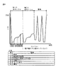
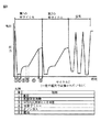
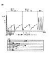
過酸化水素水の凝縮を抑制する方法が、図3の流れ図と図4から図6のサイクルグラフとに示されているように、滅菌される物品を過酸化水素とオゾンとに対して逐次的に露出させる、滅菌方法で使用できる。この物品が、真空下において、最初に過酸化水素の蒸発水溶液に対して露出させられ、その次にオゾン含有ガスに対して露出させられることが好ましい。この露出が、滅菌雰囲気の水蒸気含量を減少させることなしに行われ、かつ、この水蒸気含量が、過酸化水素溶液の水性溶媒と、水と酸素とへの過酸化水素の分解とから得られることが好ましい。滅菌チャンバが密封状態のままである間に、かつ、滅菌雰囲気のあらゆる成分の除去なしに、完全な滅菌プロセスが実現されることが最も好ましい。この目的のために、そのチャンバは、最初に、そのチャンバの雰囲気の温度において水性過酸化水素の蒸発を引き起こすのに十分な第1の真空圧になるように排気される。その次に、そのチャンバは密封されて、過酸化水素とオゾン含有ガスとが逐次的にそのチャンバに加えられ、及び、予め選択された露出期間の間、そのチャンバ内に維持される。滅菌剤の添加の最中と、露出の持続時間中は、滅菌雰囲気内のあらゆる成分の完全な除去が停止させられる。 A method for inhibiting the condensation of aqueous hydrogen peroxide is shown in the flow diagram of FIG. 3 and the cycle graphs of FIGS. Can be used in a sterilization method. This article is preferably exposed under vacuum to an aqueous hydrogen peroxide solution and then to an ozone-containing gas. This exposure is carried out without reducing the water vapor content of the sterilizing atmosphere, and this water vapor content is obtained from the aqueous solvent of the hydrogen peroxide solution and the decomposition of the hydrogen peroxide into water and oxygen. Is preferred. Most preferably, a complete sterilization process is achieved while the sterilization chamber remains sealed and without removal of any components of the sterilization atmosphere. For this purpose, the chamber is first evacuated to a first vacuum pressure sufficient to cause evaporation of aqueous hydrogen peroxide at the ambient temperature of the chamber. The chamber is then sealed and hydrogen peroxide and ozone-containing gas are sequentially added to the chamber and maintained in the chamber for a preselected exposure period. During the addition of the sterilant and the duration of exposure, complete removal of any components in the sterilizing atmosphere is stopped.
水性過酸化水素溶液は蒸発させられて、水蒸気含量を減少させる処置なしに、滅菌チャンバの中に直接的に注入される。本出願の発明者は、チャンバ内の水蒸気含量を減少させるためのあらゆる及び全ての段階が省略され、かつ、過酸化水素滅菌段階の後にオゾン滅菌段階が続く時に、過酸化水素滅菌段階中に発生させられる水蒸気が、オゾン滅菌段階を改善するために滅菌チャンバ内の雰囲気を十分に加湿するように使用されることが可能なので、使用される滅菌剤の量と滅菌サイクルの長さとが著しく減少させられることが可能であるということを、驚くべきことに発見している。同じ滅菌剤を使用する時に、依然として完全な滅菌を実現しながら、従来技術のプロセスの場合よりも著しく少ない量の過酸化水素とオゾンとが使用されることが可能である。さらに、本発明による滅菌剤の必要量が、同一のサイクルにおいて単純に2つの滅菌剤を使用することから予想される必要量よりも少ない。したがって、滅菌雰囲気中の湿度を調整する処置なしに全ての滅菌段階を通じて滅菌チャンバを密封状態に保つことが、相乗効果を結果的に生じさせると考えられる。 The aqueous hydrogen peroxide solution is evaporated and injected directly into the sterilization chamber without treatment to reduce the water vapor content. The inventor of the present application has generated during the hydrogen peroxide sterilization phase when all and all steps to reduce the water vapor content in the chamber are omitted and the ozone sterilization phase is followed by the ozone sterilization phase. The water vapor to be used can be used to sufficiently humidify the atmosphere in the sterilization chamber to improve the ozone sterilization stage, thus significantly reducing the amount of sterilant used and the length of the sterilization cycle. It is surprisingly found that it can be done. When using the same sterilant, significantly lower amounts of hydrogen peroxide and ozone can be used, while still achieving complete sterilization, compared to prior art processes. Furthermore, the required amount of sterilant according to the invention is less than would be expected from simply using two sterilants in the same cycle. Therefore, keeping the sterilization chamber sealed throughout all sterilization steps without the procedure of adjusting the humidity in the sterilization atmosphere would result in a synergistic effect.
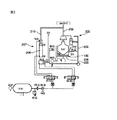
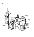
図1に概略的に示されている本発明による滅菌装置は、一般的に、次の仕方で動作する。滅菌される物品(図示されていない)が滅菌チャンバ10内に置かれ、このチャンバが密封される。真空がこのチャンバ10に加えられる。蒸発過酸化水素溶液が配送ユニット30(図8を参照されたい)から滅菌チャンバ10の中に供給されるが、これについてはより詳細に後述する。このチャンバの中に供給される蒸発過酸化水素は、物品の部分的滅菌を生じさせる。医療品質の酸素がオゾン発生器22内で電界に曝され、この電界はその酸素をオゾン含有ガスに変換する。その次に、このオゾン含有ガスはチャンバ10の中に送り込まれるが、このチャンバ10は、蒸発過酸化水素溶液の注入と、フリーラジカル(ヒドロキシル)と水と酸素とへの過酸化水素の分解とによってすでに加湿されている。オゾン含有ガスが物品の滅菌を完了する。その次に、残留する滅菌剤ガスが、触媒52を使用して水と酸素とに分解される。滅菌サイクルの最後に残る残留物は酸素と浄水だけである。
The sterilizer according to the invention, schematically shown in FIG. 1, generally operates in the following manner. An article to be sterilized (not shown) is placed in the
本発明のオゾン滅菌方法が室温で行われ、及び、したがって、滅菌済みの物品が滅菌サイクルの直後に使用されることが可能であるように、滅菌済み物品の換気又は冷却が実質的に不要であることが好ましい。さらに、使用されるガスが、滅菌される長い管腔の中により迅速に拡散し、滅菌に必要とされるサイクル時間を減少させる。このことが、高額の医療装置在庫を維持するコストを病院が低減させることを可能にする。本発明の滅菌方法は幾つかのさらに別の利点を提供する。この方法は、有毒な廃棄物を生じさせず、危険なガスシリンダの取り扱いを不要にし、及び、環境又はユーザの健康に対して脅威を及ぼさない。ステンレス鋼の器具と熱に弱い器具とが同時に取り扱われることが可能であり、このことは、特定のユーザの場合に、2つの別々の滅菌装置の必要性を取り除くだろう。 The ozone sterilization method of the present invention is performed at room temperature, and therefore, substantially no ventilation or cooling of the sterilized article is required so that the sterilized article can be used immediately after the sterilization cycle. Preferably there is. Furthermore, the gas used diffuses more quickly into the long lumen to be sterilized, reducing the cycle time required for sterilization. This allows the hospital to reduce the cost of maintaining expensive medical device inventory. The sterilization method of the present invention provides several further advantages. This method does not produce toxic waste, eliminates the need for dangerous gas cylinder handling, and does not pose a threat to the environment or user health. Stainless steel instruments and heat-sensitive instruments can be handled at the same time, which will eliminate the need for two separate sterilizers for certain users.
図1に概略的に示されている本発明による好ましい滅菌装置が、真空を閉じ込めるために密封されることが可能な滅菌チャンバ10を含む。これはアクセス扉12によって実現され、このアクセス扉12は、選択的に、滅菌チャンバの中への到達のために開かれることが可能であり、及び、その閉鎖状態において滅菌チャンバを密封する。この装置は、さらに、オゾン含有ガスを滅菌チャンバに供給するためのオゾン発生器22と、滅菌チャンバ10に蒸発過酸化水素を供給するための過酸化水素配送ユニット30と、真空ポンプ40(CM−005−052 TSO3,Inc)とを含む。真空ポンプ40は、滅菌ガスの浸透を増大させるように、かつ、滅菌チャンバの内側の温度よりも低い温度で蒸発過酸化水素溶液を発生させることが可能であるように、十分な真空を滅菌チャンバ10に加えるために使用される。好ましい実施形態の真空ポンプ40は、滅菌チャンバ内の雰囲気の実際の温度よりも低い温度に滅菌チャンバ内の水の沸点を低下させるために十分な真空を、滅菌チャンバ内に生じさせることが可能である。この好ましい装置では、真空ポンプは、133Pa(1トル(1.33mbar))の真空を生じさせることが可能である。オゾン発生器22内で発生させられるオゾンが、オゾン含有ガスが滅菌チャンバ10の通過後に又は直接的にオゾン発生器22からバイパス弁29bを通過して送り込まれるオゾン触媒52内で破壊される。オゾン触媒52(AM−004−001、TSO3 Inc)は、外気へのオゾンガスの漏出を防止するために真空ポンプ40の後に連続して連結されている。好ましい触媒52中のオゾン分解材料がカロライト(carulite)である。経済的及び実用的な理由から、滅菌チャンバ10から排出される滅菌ガスの中のオゾンの分解のために触媒を使用することが好ましい。この触媒は、特定の量の熱の発生を伴いながら、接触時に過酸化水素とオゾンを破壊して酸素と水に再変形する。このタイプの触媒とその製造業者は、オゾン発生器分野の当業者には公知であり、本明細書では詳細に説明する必要は無い。さらに、滅菌ガス中に含まれているオゾンと過酸化水素を破壊する他の手段が、当業者には容易に明らかだろう。例えば、このガスは、予め選択された時間の間、滅菌剤の分解が加速される温度に加熱されることが可能であり、例えば3秒間の時間期間の間、300℃に加熱されることが可能である。
A preferred sterilization apparatus according to the present invention schematically shown in FIG. 1 includes a
過酸化水素配送ユニット30は、リザーバ220(AM−213−010、TSO3 Inc)と、計量供給ユニット240と、導管280(AM−213−003、TSO3 Inc)を経由して滅菌チャンバ10に直接的に連結されている蒸発器ユニット260(FM−213−003、TSO3 Inc)とを含む。リザーバ220は、別の滅菌サイクルの実行のために十分に高い液位の過酸化水素を常に確保するために液位センサ222を備えている。過酸化水素溶液(3−59%)が、過酸化水素供給ユニット200(図7を参照されたい)からリザーバに供給されるが、この過酸化水素供給ユニット200についてはより詳細に後述する。過酸化水素溶液は、密封ボトル180から供給ユニット200の中に供給される(図7を参照されたい)。蒸発器ユニット260内で発生させられた蒸発過酸化水素溶液が、中間での流れの制限又は弁なしに、直接的に滅菌チャンバ10の中に入る。蒸発器ユニットが、過酸化水素溶液のより高い蒸発速度を実現しかつその凍結を防止するように十分に高い温度に過酸化水素溶液の温度を維持する加熱装置(図示されていない)を備えていることが好ましい。
The hydrogen
オゾン発生器22(OZ、model 14a、TSO3 Inc)はコロナ放電タイプであり、かつ、オゾン分解速度を低下させるために冷却されるが、このことは全て当業で公知である。オゾン発生は、熱の形でのエネルギー損失に伴われている。熱がオゾンの酸素への分解を加速するので、この熱は、オゾン発生器22の冷却によって可能な限り速やかに取り除かれるべきである。この装置内のオゾン発生器は、冷却システム60によって3℃から6℃の比較的低い温度に保たれ、この冷却システム60は、冷却水再循環を伴う間接的冷却システムであるか、又は、冷却のための空冷ユニット又は冷凍ユニットを備える直接的冷却システム(図示されていない)である。この冷却システムが3−6℃の温度に維持されることが好ましい。好ましい実施形態では、この冷却システムは、オゾン発生器22によって発生させられるオゾン含有ガスが約20℃から約35℃の周囲温度にあるように、4℃に保たれる。したがって、加湿と滅菌とのために滅菌チャンバの中に入るオゾン含有ガスは25℃から35℃の外界温度に保たれる。このことは、オゾン分解が最小限にされかつ滅菌プロセスが最も効率的であることを意味する。オゾン発生器22が、医療グレードの酸素を供給されることが好ましい。酸素は、さらに、酸素供給弁21を通して滅菌チャンバ10の中に直接的に供給されてもよい。この装置は、病院内で一般的である壁上の酸素出口に連結されることが可能であり、又は、酸素シリンダに、又は、所望の品質及び流量を供給することが可能な任意の他の供給源に連結されることが可能である。オゾン発生器22に対する酸素の供給は、フィルタ23と、圧力調整器24と、流量計25と、酸素遮断弁26とを経由して生じる。オゾン発生器は、安全圧力スイッチ27によって酸素の過剰圧力から保護されている。オゾン発生器22によって生じさせられたオゾン−酸素混合物が、流量調整器オリフィス28と混合物供給電磁弁29aとを経由して滅菌チャンバ10に送られる。この混合物は、さらに、バイパス電磁弁29b(採用随意)を経由してオゾン触媒52に直接的に供給されることも可能である。体積125リットルの滅菌チャンバが使用される好ましい実施形態では、圧力調整器24と調整器弁28とが、約13.8kPa(2psig)の圧力と約1.5リットル/分の流量とに酸素供給量を調整することが好ましい。しかし、オゾン発生器22の構造及びモデルと、滅菌チャンバのサイズとに応じて、他の流量が使用されてもよいということが、当業者には容易に明らかだろう。
The ozone generator 22 (OZ, model 14a, TSO 3 Inc) is a corona discharge type and is cooled to reduce the rate of ozonolysis, all of which are known in the art. Ozone generation is accompanied by energy loss in the form of heat. Because heat accelerates the decomposition of ozone into oxygen, this heat should be removed as quickly as possible by cooling the
滅菌チャンバ10内の真空は、真空ポンプ40と、滅菌チャンバ排液弁44とによって生じさせられる。
A vacuum in the
弁29a、29bはテフロン電磁弁(CM−900−156、TSO3 Inc)である。弁26と真空弁44は電磁弁(CM−015−004、TSO3 Inc)である。
The
本発明のプロセスと装置で使用される好ましいオゾン発生器は、コロナ放電タイプの発生器であり、この発生器は当業者に公知であり、本明細書でさらに説明される必要はない。 The preferred ozone generator used in the process and apparatus of the present invention is a corona discharge type generator, which is known to those skilled in the art and need not be further described herein.
動作
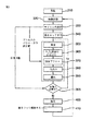
本発明による好ましい滅菌方法が、図3の流れ図に示されている次の概略的な段階を含む。医療器具のような滅菌されるべき物品が、滅菌チャンバの中に直接的に置かれるが、病院環境で一般的に使用されるような滅菌包装容器、滅菌ラップ又は滅菌パウチ内に密封され、その後で滅菌チャンバ内に入れられることが好ましい。様々な異なるタイプのこうした容器又はパウチが当業者には公知であり、本明細書でさらに説明される必要はない。
Operation A preferred sterilization method according to the present invention comprises the following schematic steps shown in the flow diagram of FIG. An article to be sterilized, such as a medical instrument, is placed directly in the sterilization chamber, but sealed in a sterile packaging container, sterilization wrap, or sterilization pouch as commonly used in a hospital environment, and then In a sterilization chamber. A variety of different types of such containers or pouches are known to those skilled in the art and need not be further described herein.
段階320において、滅菌される物品の挿入物が滅菌チャンバの中に入れられ終わった後に、段階340において、滅菌チャンバの扉が閉められてそのチャンバが密封され、及び、段階350において、そのチャンバ内の圧力が133Pa(1トル(1.33mbar))の第1の圧力に達し終わるまで、真空が滅菌チャンバに加えられる。予熱段階310において、滅菌チャンバの壁が40℃の温度に予熱され終わっていることが好ましい。加湿段階360において、滅菌チャンバを部分的に滅菌して加湿するために、蒸発過酸化水素溶液が滅菌チャンバの中に受け入れられる。2527Pa(19トル)の圧力増大が滅菌チャンバ内で実現され終わると、蒸発過酸化水素溶液の注入が停止させられる。滅菌チャンバは、過酸化水素がその最中に少なくとも部分的にフリーラジカルと水と酸素の形に分解する第1の露出期間370(2分であることが好ましい)の間、密封状態に維持されることが可能である。好ましくは、この露出期間が省かれることも可能である。その次に、乾燥オゾンと酸素の混合物の形態であることが好ましいオゾン含有ガスが、オゾン注入段階380において、滅菌チャンバに供給され、このチャンバが、予め選択された第2の露出期間390の間、密封状態にされる。チャンバの雰囲気が過酸化水素溶液によって加湿され終わっているので、オゾン含有ガスの加湿は行われないか、又は、不要でさえある。真空の付与の合間に、過酸化水素の蒸発段階の前に、及び、第2の露出期間の終了の前に、滅菌雰囲気の成分のどれもが第2の露出期間の終了前に除去されないように、あらゆる滅菌雰囲気成分の完全な除去が中止される。真空の付与の段階、第1の露出期間を伴う過酸化水素の注入の段階、及び、第2の露出期間を伴うオゾンガスの注入の段階が、少なくとも1回は反復されることが好ましく、及び、この反復の回数は、段階330において前もって選択されたサイクルに基づいて段階395において決定される。滅菌サイクルの完了後に滅菌チャンバ10から残留滅菌剤の全てを取り除くために、換気期400が開始され、この換気期が、滅菌チャンバの排気と酸素による洗い流しとの複数のサイクルを含むことが好ましい。この換気期400の後に、段階410において扉がロック解除され、滅菌された物品が滅菌チャンバから取り出されることが可能である。滅菌チャンバの床と扉の温度と蒸発器ユニットの温度とが、滅菌プロセス全体を通じて調整されることが好ましい。
In
本発明による例示的な滅菌装置では、ユーザは複数の異なる滅菌サイクルの選択が可能である。好ましい方法では、このプロセスのサイクル選択段階330において、ユーザは、表1に示されておりかつ後述されるそれぞれの特性を有する3つのサイクルの中から選択することが可能である。

サイクル2 − オゾンとの高い適合性を有する表面装置、ヒンジ付き器具、及び、硬質の内視鏡(1mm×50cm)。
サイクル3 − サイクル#1によって滅菌可能な器具、及び、複雑な内視鏡(例えば、胃カメラ、大腸内視鏡)。
In an exemplary sterilizer according to the present invention, a user can select a plurality of different sterilization cycles. In the preferred method, in the
Cycle 2-Surface device with high compatibility with ozone, hinged instrument, and rigid endoscope (1 mm x 50 cm).
Cycle 3-Instruments that can be sterilized by
50%過酸化水素溶液を使用してこの滅菌プロセスを行うことが好ましいが、このプロセスは、30%−50%の過酸化水素を含む溶液を使用して行われることが可能である。3%、30%、及び、50%の過酸化水素溶液を使用して行われる時のこのプロセスの例示的な条件が次の通りである。
最大注入圧力は、蒸発過酸化水素溶液の注入が停止される圧力である。条件調整時間が、滅菌される物品が滅菌チャンバ内に保たれ、かつ、約40℃に加熱されているチャンバの壁と床と扉によって室温から次第に温度上昇する、滅菌チャンバの封止後と真空の付与の前の時間期間を表す。チャンバ内のロード(load)のこの加温は、蒸発過酸化水素溶液の注入時におけるロード上の水の不要な凝縮を防止するために必要とされる。この凝縮のリスクは、過酸化水素溶液の濃度の低下につれて増大する。 The maximum injection pressure is a pressure at which injection of the evaporated hydrogen peroxide solution is stopped. Conditioning time is that after the sterilization chamber is sealed and vacuum, the article to be sterilized is kept in the sterilization chamber and gradually warmed from room temperature by the chamber wall, floor and door being heated to about 40 ° C. Represents the time period before granting. This warming of the load in the chamber is required to prevent unwanted condensation of water on the load during injection of the evaporated hydrogen peroxide solution. This risk of condensation increases with decreasing concentration of the hydrogen peroxide solution.
ユーザがこの3つのサイクルの1つを選択し終わると、そのユーザは滅菌チャンバの扉を閉め、開始ボタンを押す。その次に、滅菌装置制御システム(図9を参照されたい)が、組み込まれている操作ソフトウェアの制御を受けて、選択されたサイクルに関する予め選択されたパラメータを使用して、選択されたサイクルによる滅菌プロセスを開始する。滅菌ロードの事前の条件調整はない。このサイクルは、約133Pa(約1トル(1.33mbar))の滅菌チャンバ内の真空の発生から開始する。その次に、蒸発水性過酸化水素溶液が、ロードを部分的に滅菌及び加湿するために、蒸発器ユニットを通して滅菌チャンバの中に注入される。過酸化水素溶液は、蒸発器ユニットの中に入る前に、図8に示されている計量供給ユニット240の中を通過する。この計量供給ユニット240は蒸発器ユニット260に直接的に連結されており、及び、したがって、滅菌チャンバ内に存在する真空圧を受ける。計量供給ユニット240は基部ブロック241を含み、この基部ブロックは固定された既知の体積の通路(図示されていない)を有し、この通路は、その通路の上流側の末端において吸い込み弁242によって過酸化水素リザーバ220に連結されており、かつ、この通路の下流側の末端において排出弁243によって蒸発器ユニット260に連結されている。計量供給ユニット240を通過する過酸化水素溶液の流量は、弁242、243によって正確に制御されることが可能であり、これらの弁は、他方の弁が開いている時には一方の弁が常に閉じられており、かつ、両方の弁が同時には開かないように、互いに反対に切り替えられかつ非オーバーラップ(non−overlapping)である。このようにして、この通路は、排出弁243が開いておりかつ吸い込み弁242が閉じている時に排出され、及び、排出弁243が閉じておりかつ吸い込み弁242が開いている時に過酸化水素溶液で満たされ、及び、排出弁243が再び開いておりかつ吸い込み弁242が再び閉じている時に再び排出される。この通路の正確な体積が分かっているので、弁サイクル毎に供給される過酸化水素溶液の量が分かっており、過酸化水素の合計量が弁開閉サイクルの回数に基づいて計算されることが可能である。弁242、243が開閉する回数と頻度が装置のソフトウェアによって制御及び監視され、及び、供給ボトルから吸い込まれた合計量と計量供給された量とに基づいて、リザーバから取り出された過酸化水素溶液の量を求めるために、及び、リザーバ内の溶液の理論的な残留量を計算するために、使用されることが可能である。本発明の装置及び方法の発明者は、一般的な認識とは反対に、チャンバ内に供給される蒸発過酸化水素の正確な量が重要ではないということを発見している。これとは反対に、本出願の発明者は、過酸化水素蒸気の滅菌効果の最も確実な決定要因がチャンバ内の圧力であるということを驚くべきことに発見している。この滅菌効果は、過酸化水素による滅菌雰囲気の飽和レベルに依存している。しかし、この飽和レベルは、チャンバ内のロードと、ロード中の材料の吸収特性とに大きく依存するので、注入される溶液の量からは確実には計算不可能である。しかし、この飽和レベルはチャンバ内の圧力に直接的に比例している。したがって、チャンバ内の飽和レベルは、チャンバ内への注入された過酸化水素溶液の流量又は量を測定することによってではなく、チャンバ圧力に基づいてのみ求められることが可能である。この結果として、本発明の実施形態における過酸化水素注入段階360中の弁開閉サイクルの回数は、過酸化水素注入の完了時においてチャンバ10内で達する圧力に完全に依存している。好ましい実施形態では、50%水性過酸化水素溶液が使用され、チャンバ内で達しなければならない圧力増大が2527Pa(19トル)である。事前設定された2527Pa(19トル)の圧力増大の到達の後に、採用随意の2分間の保圧時間が続く。その次に、1回分の乾燥オゾン含有ガスが注入され、その後に第2の露出期間が続く。このオゾンの用量は、ユーザによって選択されるサイクルによって決まる。第1及び第2の部分的滅菌段階の所望の回数の反復が行われる時に、過酸化水素及びオゾン滅菌剤の残留物を取り除くために、酸素によってチャンバを3回にわたって排気及び再充填することによって、滅菌チャンバ10の換気が行われる。
When the user has selected one of the three cycles, the user closes the sterilization chamber door and presses the start button. Then, the sterilizer control system (see FIG. 9) is under the selected cycle using preselected parameters for the selected cycle under the control of the embedded operating software. Start the sterilization process. There is no preconditioning of the sterilization load. This cycle begins with the generation of a vacuum in a sterilization chamber of about 133 Pa (about 1.33 mbar). The evaporated aqueous hydrogen peroxide solution is then injected through the evaporator unit into the sterilization chamber to partially sterilize and humidify the load. The hydrogen peroxide solution passes through the
条件調整期中に各パルスによって注入される過酸化水素の体積における変化が、滅菌の有効性と、ロード上で観察される凝縮物の量とに対して影響を与えるかどうかを判定するために、本出願人は、異なる注入パルス量で滅菌試験を行った。理論的には、過酸化水素の注入/蒸発の速度が滅菌の有効性に影響を与える可能性があった。各パルス中に著しくより大きな体積を注入することによって、その溶液がチャンバ内により迅速に押し込まれ、及び、その液体が蒸発する時間が減少させられる。したがって、器具上又は包装材料上により多くの凝縮物が生じる機会がより一層多い。過剰に顕著である凝縮物が2つの問題点を生じさせることが予想される。第1に、顕著な凝縮が、器具の表面において胞子にオゾンが到達する能力を制限する可能性があった。第2に、過酸化水素液が包装材料内に閉じ込められたままになり、後でその滅菌されたロードを取り扱う人々にとって有害である可能性があった。閉じ込められた過酸化水素液の量が過剰に多い場合には、滅菌サイクルの終了時におけるチャンバとパッケージングとの換気が、過酸化水素凝縮物の全ての残留物を取り除くには不十分であることがある。 To determine whether the change in the volume of hydrogen peroxide injected by each pulse during the conditioning period has an impact on the effectiveness of sterilization and the amount of condensate observed on the load, The Applicant has performed sterilization tests with different injection pulse volumes. Theoretically, the rate of hydrogen peroxide injection / evaporation could affect the effectiveness of sterilization. By injecting a significantly larger volume during each pulse, the solution is pushed more rapidly into the chamber and the time for the liquid to evaporate is reduced. Thus, there are even more opportunities for more condensate to occur on the appliance or on the packaging material. It is expected that condensate that is overly prominent will give rise to two problems. First, significant condensation could limit the ability of ozone to reach the spores at the instrument surface. Second, the hydrogen peroxide solution could remain trapped within the packaging material and could be detrimental to those who later handle the sterilized load. If the amount of entrapped hydrogen peroxide solution is excessive, ventilation of the chamber and packaging at the end of the sterilization cycle is not sufficient to remove all residues of hydrogen peroxide condensate Sometimes.
滅菌チャンバ内の圧力が大気圧よりも低下させられている時には、チャンバ内に存在しているか又はチャンバ内に注入されるあらゆる液体が、大気条件における場合よりも低い温度で沸騰するだろう。本プロセスの上記の実施形態では、チャンバ内の圧力は最初に低下させられ、及び、その次に、ある一定の体積の過酸化水素が蒸気の形態で注入される。使用される過酸化水素の全体積が小さい増分で注入される。注入中は、チャンバ内の圧力が、2660Pa(20トル)(133Pa(1トル)の開始圧力+2527Pa(19トル)の圧力増大)の最終圧力に達するまで増大する。過酸化水素は水よりも高い温度で蒸発する(50%過酸化水素の沸点は114℃であり、水の沸点は100℃である)。したがって、凝縮物は、チャンバの中に入る初期溶液よりも過酸化水素においてより濃縮されるだろう。この現象は、チャンバ内に配置されているUVランプによって観察された。チャンバ内の圧力が増大していた場合にさえ、UVランプによって読み取られた蒸気中の過酸化水素の濃度は減少していた。さらに、第1の過酸化水素液滴の濃度(1330Pa(10トル))が滴定された。その液体が約85%の濃縮過酸化水素であることが発見された。 When the pressure in the sterilization chamber is reduced below atmospheric pressure, any liquid present in or injected into the chamber will boil at a lower temperature than in atmospheric conditions. In the above embodiment of the process, the pressure in the chamber is first reduced and then a certain volume of hydrogen peroxide is injected in the form of a vapor. The total volume of hydrogen peroxide used is injected in small increments. During the injection, the pressure in the chamber increases until it reaches a final pressure of 2660 Pa (20 Torr) (133 Pa (1 Torr) start pressure + 2527 Pa (19 Torr) pressure increase). Hydrogen peroxide evaporates at a higher temperature than water (50% hydrogen peroxide has a boiling point of 114 ° C. and water has a boiling point of 100 ° C.). Thus, the condensate will be more concentrated in hydrogen peroxide than the initial solution entering the chamber. This phenomenon was observed with a UV lamp placed in the chamber. Even when the pressure in the chamber was increasing, the concentration of hydrogen peroxide in the vapor read by the UV lamp was decreasing. In addition, the concentration of the first hydrogen peroxide droplet (1330 Pa (10 Torr)) was titrated. It was discovered that the liquid was about 85% concentrated hydrogen peroxide.
約1330Pa(約10トル)の圧力では、過酸化水素の微量凝縮物(micro−condensation)の層がチャンバ内の物体上に現れた。この微量凝縮物の厚さは数分子分の厚さにすぎないと計算されたが、過酸化水素が蒸気の形態と液体の形態とにおいて滅菌することが可能であるということが公知なので(Chung他、2006、及び、Unger−Bimczok他、2008)、滅菌を補助することが可能である。さらに、オゾンは過酸化水素中でより溶けやすく、及び、胞子が存在している表面においてラジカルを形成することが可能である。 At a pressure of about 1330 Pa (about 10 Torr), a layer of hydrogen-condensation micro-condensation appeared on the object in the chamber. The thickness of this microcondensate was calculated to be only a few molecules thick, but it is known that hydrogen peroxide can be sterilized in vapor and liquid forms (Chung Et al., 2006, and Unger-Bimczok et al., 2008), which can assist in sterilization. Furthermore, ozone is more soluble in hydrogen peroxide and can form radicals on the surface where spores are present.
一度に大きな体積の注入を行うために、テフロン管材料で分離された弁が、通常使用されるマイクロバルブ(microvalve)(AM−213−001、TSO3 Inc.)の代わりに使用された。この管材料の長さが、注入される体積によって決定された。この弁の中に含まれる体積が大きいので、2つサイズの弁が使用された。0.062″のオリフィスを有する第1のタイプ(TSO3 #:CM−900−157)が、1.5mLまでの体積に対して使用された。0.156″のオリフィスを有する第2のNeptuneタイプ(AM−900−156、TSO3 Inc.)が、3.5mLまでの体積に対して使用された。より大きい弁サイズは、さらに、大きな液体体積をチャンバ内に送り込むことを補助する。35μLの体積に関しては、Burket 7616マイクロポンプ(CM−113−001、TSO3 Inc.)が使用された。23μLの体積に関しては、より大きい、特別に作られたブロックが使用された。 To perform large volume injections at once, a valve separated with Teflon tubing was used instead of the commonly used microvalve (AM-213-001, TSO3 Inc.). The length of the tube material was determined by the volume injected. Due to the large volume contained in this valve, two sizes of valves were used. A first type (TSO3 #: CM-900-157) with an orifice of 0.062 "was used for volumes up to 1.5 mL. Second Neptune type with an orifice of 0.156" (AM-900-156, TSO3 Inc.) was used for volumes up to 3.5 mL. The larger valve size further assists in delivering a large liquid volume into the chamber. For a volume of 35 μL, a Burket 7616 micropump (CM-113-001, TSO3 Inc.) was used. For a volume of 23 μL, a larger, specially made block was used.
2つのサイクルがこの実験のために使用された。無菌状態を試験するために、サイクル1(半サイクル)が使用され、この場合には、上述したように、条件調整期の注入段階が、各試行毎の体積及びパルスの変化によって変更された。凝縮物の効果に関しては、4つの期から成るサイクル3が使用された。このサイクルは、そのサイクルに関してより多い量の過酸化水素が注入されてそのサイクルを最悪のケースシナリオにしたという事実の故に選択された。第3の試験が無菌状態の試験のために行われた。管腔(テフロン、1mm×80cm)が、MCB−09−A07にしたがってワイヤ方法を使用して接種処理された。サイクル1の半サイクルに対する露出の後に、各々の管腔の無菌状態が、超音波法とその後の濾過とを使用する量的回収によって、MCB−09−A07 rev.7にしたがって判定された。
Two cycles were used for this experiment. To test sterility, cycle 1 (half cycle) was used, in which case the conditioning phase injection phase was altered by changes in volume and pulse for each trial, as described above. Regarding the effect of condensate,
注入された体積を正確に求めるために、ビュレットがこの弁システム上に差し込まれた。その次に、この体積がパルス数で割り算された。3つのTSO3サイクルが、これら3つのサイクルに関する平均ロードを表す特別なロードを用いて試験された。サイクルの開始時にはこのロードは常に室温にあった。UVランプも、使用された滅菌装置上に備えられた。このことが、条件調整期中における過酸化水素蒸気の分析を可能にした。 A burette was inserted over the valve system to accurately determine the volume injected. This volume was then divided by the number of pulses. Three TSO3 cycles were tested with a special load representing the average load for these three cycles. This load was always at room temperature at the start of the cycle. A UV lamp was also provided on the sterilizer used. This enabled the analysis of hydrogen peroxide vapor during the conditioning period.
無菌状態が、管材料の中に装入されたテフロンワイヤ(1mm×80cm)を用いて検証され、及び、サイクル1の半サイクル内で試験された。条件調整期中の各パルスによる第1の注入体積が1.5mLだった。滅菌効果に関して良好な結果の場合には、体積が2倍にされただろう。結果が不十分であった場合には、その体積の半分が試験されただろう。1パルス当たり1.5mLを使用した試験の結果が良好だったので、その試験を2.5mLと3.4mLとを用いて繰り返した。2394Pa(18トル)の所望の圧力に達するために2つパルスだけしか必要ではなかったので、試験が3.4mLの注入で中止された。通常の条件調整期は2527Pa(19トル)で止まったが、圧力が超過されなかったことを確実なものにするために、マイクロバルブが2394Pa(18トル)から2527Pa(19トル)の間で使用された。
Sterility was verified using a Teflon wire (1 mm x 80 cm) loaded into the tubing and tested within a half cycle of
3.4mLで無菌状態が得られた(全ての試験が胞子カウントに関してゼロだった)。したがって、本出願人は、パルス体積の変動が滅菌効果にまったく影響しないということを発見した。しかし、過酸化水素がチャンバ内に注入される場所に凝縮物が存在したということを滅菌試験中に発見した。したがって、各パルス毎に凝縮なしに注入されることが可能な最大体積を求めるために、より多くの試験が行われた。 Sterility was obtained with 3.4 mL (all tests were zero for spore count). The Applicant has therefore found that pulse volume variations do not affect the sterilization effect at all. However, it was discovered during the sterilization test that condensate was present where hydrogen peroxide was injected into the chamber. Therefore, more tests were performed to determine the maximum volume that could be injected without condensation with each pulse.
注入された第1の体積が再び1.5mLだった。凝縮物が注入場所においてロード上に存在した。測定された液体凝縮物の量が、3.4mLの注入パルスで観察されたものと同じだった。その次に、このパルス量が、それ以上多くの凝縮物が見えなくなるまで、1回毎に半分ずつ注入量を減少させることによって段階的に減少させられた。75μLでは、凝縮物は、再び、3.4mLの注入パルスの場合と同じだった。凝縮物形成における著しい減少が、75μLのパルス体積よりも低いパルス体積で観察された。35μLでは、凝縮物が依然として目視できたが、著しく減少した。23μLでは、凝縮物は殆ど目視できなかった。16μLのパルス体積では、凝縮物は全く完全に観察できなかった。凝縮物が約20μLのより大きいパルス体積で生じることが発見された。したがって、過酸化水素の不要な凝縮物の量を調整するためには、75μL未満のパルス注入体積を使用することが好ましく、35μLより小さいパルス注入体積を使用することがより好ましく、約20μLのパルス注入体積を使用することが最も好ましい。 The first volume injected was 1.5 mL again. Condensate was present on the load at the injection site. The amount of liquid condensate measured was the same as that observed with a 3.4 mL injection pulse. The pulse volume was then reduced in steps by decreasing the injection volume by half each time until no more condensate was visible. At 75 μL, the condensate was again the same as for the 3.4 mL injection pulse. A significant decrease in condensate formation was observed at pulse volumes lower than 75 μL pulse volume. At 35 μL, condensate was still visible, but was significantly reduced. At 23 μL, almost no condensate was visible. With a pulse volume of 16 μL, no condensate could be observed at all. It has been discovered that condensate occurs with a larger pulse volume of about 20 μL. Thus, to adjust the amount of unwanted condensate of hydrogen peroxide, it is preferable to use a pulse injection volume of less than 75 μL, more preferably a pulse injection volume of less than 35 μL, Most preferably, an injection volume is used.
本発明による例示的なプロセスでは、滅菌チャンバの壁が温度40℃に維持され、一方、ロード温度が20℃と25℃の間で変化するだろう。使用される過酸化水素溶液の濃度は50%であることが好ましいが、3%程度の低濃度と59%程度の高濃度とが使用可能である。チャンバ内で到達される圧力が、使用される過酸化水素濃度(表IIを参照されたい)の関数である。到達する圧力が上記の各サイクルに関して同一であっても、必要とされる過酸化水素溶液の体積は、その溶液の濃度と、チャンバ内のロードのタイプと、そのロードの過酸化水素吸収能力とに依存する。オゾン注入前の滅菌雰囲気内の加湿レベルが、過酸化水素溶液の異なる濃度を使用することによって調整されることが可能である。 In an exemplary process according to the present invention, the walls of the sterilization chamber are maintained at a temperature of 40 ° C, while the load temperature will vary between 20 ° C and 25 ° C. The concentration of the hydrogen peroxide solution used is preferably 50%, but a low concentration of about 3% and a high concentration of about 59% can be used. The pressure reached in the chamber is a function of the hydrogen peroxide concentration used (see Table II). Even if the pressure reached is the same for each of the above cycles, the volume of hydrogen peroxide solution required depends on the concentration of the solution, the type of load in the chamber, and the hydrogen peroxide absorption capacity of the load. Depends on. The humidification level in the sterile atmosphere before ozone injection can be adjusted by using different concentrations of the hydrogen peroxide solution.
オゾンの用量は、サイクル#1の場合の2mg/lとサイクル#2の場合の10mg/lの間で変化し、及び、その露出期間は、サイクル#1の場合の5分間とサイクル#3の場合の10分間の間で変化する。
The dose of ozone varies between 2 mg / l for
滅菌ガスとして加湿されたオゾンを使用する従来技術の滅菌プロセスで使用されるオゾンの量が一般的に約85mg/lである。オゾン注入前のロードの部分的滅菌と加湿とのために過酸化水素を使用することが、選択されたサイクルに応じて、2mg/lから10mg/lの間の用量までの、滅菌(SAL 10-6)を実現するために必要とされるオゾンの量の大きな減少を可能にする。この減少は、過酸化水素とオゾンが同一の滅菌サイクルで使用されるという事実だけから予想される減少よりも著しく大きい。 The amount of ozone used in prior art sterilization processes using humidified ozone as the sterilizing gas is typically about 85 mg / l. The use of hydrogen peroxide for partial sterilization and humidification of the load prior to ozone injection is sterilization (SAL 10) to doses between 2 mg / l and 10 mg / l, depending on the cycle selected. -6 ) Enables a significant reduction in the amount of ozone required to achieve. This decrease is significantly greater than expected due to the fact that hydrogen peroxide and ozone are used in the same sterilization cycle.
実際にはチャンバ内に注入される蒸発過酸化水素溶液は滅菌を実現するためには不十分であるが、胞子の4logの減少が観察されている。しかし、滅菌雰囲気1リットル当たりオゾン1−10mgの範囲内の非常に少量のオゾンだけを加えることが、FDAのSecurity Assurance Level規格又は例えばISO(SAL 10-6)のような世界規格で必要とされるレベルの十分かつ完全な滅菌を結果的に生じさせる。この完全な滅菌は、使用される過酸化水素溶液の量とその溶液の濃度とは無関係に、蒸発過酸化水素溶液の注入だけを使用することによっては実現不可能だった。さらに、過酸化水素の高濃度が特定の器具との適合性を低下させる。これに加えて、例えば2分間の代わりに3分間の、過酸化水素注入後のより長い保圧時間が、滅菌効果を増強することはない。実際的には、過酸化水素注入後の保圧時間は滅菌効果に全く影響しない。さらに、上述したように、少量のオゾンだけを添加することが、驚くべきことに完全な滅菌を生じさせる。 In practice, the evaporated hydrogen peroxide solution injected into the chamber is insufficient to achieve sterilization, but a 4 log reduction in spores has been observed. However, only a very small amount of ozone in the range of 1-10 mg ozone per liter of sterile atmosphere is required by FDA's Security Assurance Level standards or world standards such as ISO (SAL 10-6 ), for example. Results in a level of sufficient and complete sterilization. This complete sterilization was not feasible by using only an injection of evaporated hydrogen peroxide solution, regardless of the amount of hydrogen peroxide solution used and the concentration of the solution. In addition, the high concentration of hydrogen peroxide reduces compatibility with certain instruments. In addition, a longer hold time after hydrogen peroxide injection, for example 3 minutes instead of 2 minutes, does not enhance the sterilization effect. In practice, the pressure holding time after hydrogen peroxide injection has no influence on the sterilization effect. Furthermore, as mentioned above, adding only a small amount of ozone surprisingly results in complete sterilization.
排出段階350(図3を参照されたい)中に、酸素供給弁21、26と、混合物供給弁29aと、混合物バイパス弁29bとが閉じられ、及び、チャンバ排液弁44が開かれる。滅菌チャンバ10が約133Pa(約1トル(1.33mbar))の圧力に排気される。滅菌チャンバ上の圧力センサ13によって測定されるこの圧力に達すると、チャンバの排液弁44が閉じられ、及び、計量供給ユニット240が、蒸発器ユニット260に過酸化水素溶液を供給するために起動され、この蒸発器ユニット260内では過酸化水素溶液が蒸発させられた後に滅菌チャンバ10内に自由に流れ込む。圧力センサ13によって測定される滅菌チャンバ10内の圧力増大が2527Pa(19トル)に達すると、計量供給ユニット240は作動停止させられ、蒸発器260への過酸化水素溶液の供給が停止させられる。2分間にわたって続くことがある後続の第1の露出期間370の最中にあらゆる物質の注入が生じないように、チャンバが密封状態に維持されることが可能である。しかし、その露出期間は完全に随意である。過酸化水素注入段階360(通常は約2−6分間)の終了の直前に、オゾン発生器が、オゾン含有ガスの供給を確実なものにするために起動される。オゾン発生器から出て行く酸素/オゾン混合物の流量が、真空に抵抗することが可能でありかつ毎分1−3リットルに流量を調整することが可能である調整器オリフィス28によって。常に調整される。オゾン発生器22の作動は、供給弁26と混合物バイパス弁29bの開放を含む。供給弁26は、酸素をオゾン発生器の中に流入させる。その次に、この発生器によって生じさせられたオゾン/酸素混合物は、混合物バイパス弁29bを経由してオゾン触媒52の中に直接的に送り込まれる。段階370の完了後に、発生器22によって発生させられた酸素/オゾン混合物は、混合物供給弁29を開きかつ混合物バイパス弁29bを閉じることによって、滅菌チャンバ10の中に直接的に送り込まれる。選択されたサイクルにしたがった所望のオゾン濃度にチャンバ内で達するまで、酸素/オゾン混合物がチャンバ10の中に入る。この段階に要する時間は、当業で公知のタイプのオゾン監視装置15によって測定される、混合物中のオゾンガスの流量と濃度(好ましくは、160−200mg/l NTP)に依存している。所望の濃度に達し終わった後に、滅菌チャンバを密封しかつオゾン/酸素ガス混合物を真空下でチャンバ内に保つために、混合物供給弁29aが閉じられる。
During the drain stage 350 (see FIG. 3), the
チャンバ内への滅菌ガス(酸素とオゾンガスの混合物)の供給が停止された後に、発生器22は停止させられ、及び、酸素供給弁26が閉じられる。ユーザによって選択された滅菌サイクルに応じて、5−10分間の露出期間にわたって滅菌チャンバが密封状態に維持される。同様に、選択されたサイクルに応じて、滅菌が完了する前に、段階350から段階390が1回から3回以上の回数にわたって繰り返される。この設定は10-6(SAL 10-6)のSecurity Assurance Level規格に準拠した。
After the supply of sterilization gas (a mixture of oxygen and ozone gas) into the chamber is stopped, the
完全滅菌後に滅菌チャンバ10内の残留する過酸化水素とオゾンと湿気とを全て取り除くために、換気期400が行われる。この換気期は最終の露出期間390の後に行われる。チャンバ排液弁44が開かれ、及び、約650MPa(約6.5mbar)まで真空が加えられる。650MPa(6.5mbar)の真空圧が得られた後に、排液弁44が閉じられ、酸素供給弁21が開き、酸素を滅菌チャンバ10の中に受け入れる。大気圧に達すると、酸素供給弁21が閉じられ、滅菌チャンバ排液弁44が開かれ、及び、130MPa(1.3mbar)の圧力に達するまで真空が再び加えられる。130MPa(1.3mbar)までのこの最後の換気サイクルが、合計3つの換気サイクルの間に1回繰り返される。最後のサイクルの後に大気圧に達した後に、滅菌チャンバの内容物に対するアクセスを可能にするために、滅菌チャンバの扉機構が段階410で起動される。この換気期は2つの機能を有する。第1に、アクセス扉を開く前に滅菌チャンバ内の全ての滅菌剤残留物を取り除くために、及び、第2に、真空圧が加えられる時に滅菌済みの材料を蒸発によって乾燥させるために。当然であるが、所望の滅菌剤除去と乾燥とが実現される限りは、異なる真空圧とサイクル時間と反復回数とが適用されることが可能である。
A
滅菌チャンバ10から排出される滅菌剤と湿気含有ガスとが、滅菌剤の完全な分解を確実なものにするために、大気中へのそのガスの排出の前に触媒52上を通過させられる。この触媒52は、滅菌サイクルの2つの部分、すなわち、(弁26、29bを伴う)発生器22の起動中と滅菌チャンバ10の排出中にだけ使用される。発生器22の始動期中に、混合物バイパス弁29bが開かれ、及び、オゾンが触媒52を通過させられる。発生器22の始動期が終了すると、バイパス弁29bが閉じる。滅菌チャンバ10の換気中に、滅菌チャンバ排液弁44が開かれ、オゾンを含む滅菌廃棄ガスが触媒52に導かれる。滅菌チャンバ10の排出が完了されると、排液弁44が閉じられる。オゾンの循環が真空ポンプ40によって確保される。触媒52は真空ポンプ40の上流側又は下流側に配置されることが可能である。
The sterilant and moisture-containing gas exhausted from the
実際には、20℃において水が0.023MPa(23.3mbar)の絶対圧にまで沸騰し、及び、35℃において水が0.056MPa(56.3mbar)の絶対圧にまで沸騰する。滅菌チャンバ内の真空が、水の沸騰温度が滅菌チャンバ内の温度よりも低下させられる圧力に調整されることが好ましい。この沸騰温度は非常に低く、蒸発器ユニット内の過酸化水素溶液の温度が急速に低下し、及び、周囲構造から得られるエネルギーに応じて、エネルギーの供給が実現されない場合にはこの過酸化水素溶液が凍結することがある。過酸化水素溶液を蒸発させるために必要とされるエネルギーは様々な供給源から得られる。このエネルギーは、主に、蒸発器ユニット260の主本体から得られ、この主本体は、加熱装置(図示されていない)が備えられているアルミニウムブロックの形である。この蒸発プロセスは、さらに、湿気が滅菌チャンバ壁上に凝縮する温度に加湿装置を冷却することもある。これは、少なくとも室温(好ましくは40℃)にチャンバ壁を維持するのに十分なだけチャンバ壁を加熱することによって回避される。これは、加熱装置(図示されていない)によって実現され、この加熱装置は当業者には容易に明らかだろう。
In practice, water boils to an absolute pressure of 0.023 MPa (23.3 mbar) at 20 ° C. and water boils to an absolute pressure of 0.056 MPa (56.3 mbar) at 35 ° C. The vacuum in the sterilization chamber is preferably adjusted to a pressure at which the boiling temperature of water is lowered below the temperature in the sterilization chamber. This boiling temperature is very low, the temperature of the hydrogen peroxide solution in the evaporator unit drops rapidly and, depending on the energy available from the surrounding structure, this hydrogen The solution may freeze. The energy required to evaporate the hydrogen peroxide solution can be obtained from various sources. This energy is mainly derived from the main body of the
滅菌チャンバ内に注入される蒸発過酸化水素溶液は、滅菌チャンバ内の相対湿度を増大させる。この加湿は、オゾン滅菌段階の効果を著しく改善する。酸素/オゾン含有ガスが、外界に近い温度で、加湿された滅菌チャンバ内に注入される。オゾン含有ガスは注入前には加熱されない。 Evaporated hydrogen peroxide solution injected into the sterilization chamber increases the relative humidity within the sterilization chamber. This humidification significantly improves the effectiveness of the ozone sterilization stage. An oxygen / ozone containing gas is injected into the humidified sterilization chamber at a temperature close to the outside world. The ozone-containing gas is not heated before injection.
過酸化水素は、医療器具を滅菌する時にその限界を示す。H2O2は、例えばステンレス鋼のような金属に接触する時に安定性が低下する。この問題が、化学反応が加速される低圧力において悪化させられる。したがって、過酸化水素の分解が真空下で加速され、及び、長い金属管材料を滅菌するために使用可能な時間を限定する。さらに、H2O2がガスではないので、H2O2の拡散が制限される。過酸化水素は拡散によって長い管材料の末端に到達するだろうが、その到達時点までに、加速された分解のせいで、滅菌には不十分なレベルにまでその濃度が低下し終わっているだろう。 Hydrogen peroxide exhibits its limitations when sterilizing medical devices. H2O2 is less stable when it comes in contact with a metal such as stainless steel. This problem is exacerbated at low pressures where chemical reactions are accelerated. Thus, the decomposition of hydrogen peroxide is accelerated under vacuum and limits the time available for sterilizing long metal tube materials. Furthermore, since H2O2 is not a gas, the diffusion of H2O2 is limited. Hydrogen peroxide will reach the end of the long tube material by diffusion, but by that time it has been reduced in concentration to a level insufficient for sterilization due to accelerated degradation. Let's go.
本出願人は、上述したように、これらの問題がオゾンのような滅菌剤ガスの添加によって克服可能であるということだけでなく、過酸化水素のフリーラジカルへの分解による滅菌チャンバの加湿が滅菌剤ガスの効果を改善するということを発見している。さらに、本出願人は、オゾンが亜酸化窒素すなわち一酸化窒素によって有利に置き換えられることが可能であるということを驚くべきことに発見している。本出願人は、過酸化水素の分解中に発生される水と酸素も一酸化窒素の効果を改善するということを発見した。 Applicants have not only said that these problems can be overcome by the addition of a sterilant gas such as ozone, as described above, but that humidification of the sterilization chamber by decomposition of hydrogen peroxide into free radicals is sterilization It has been discovered that the effect of the agent gas is improved. Furthermore, the Applicant has surprisingly found that ozone can be advantageously replaced by nitrous oxide or nitric oxide. Applicants have discovered that water and oxygen generated during the decomposition of hydrogen peroxide also improve the effectiveness of nitric oxide.
亜酸化窒素(すなわち一酸化窒素)は、低濃度において細胞に有毒であることが知られている。水と酸素の存在下では、NOが反応して二酸化窒素NO2を形成するが、この二酸化窒素も非常に有毒である。酸素の不在下では、NOはNO2を形成しないが、反応して硝酸を形成し、この硝酸は他の材料に対して非常に腐食性である。
過酸化水素の予備調整後の所要NO濃度が非常に低いので、硝酸形成の問題は、水ではなく過酸化水素と一酸化窒素を混合することによって最小限にされる。H2O2処理が胞子被膜を弱体化し、及び、過酸化水素と一酸化窒素は、互いに混合されると、オゾンが過酸化水素と混合される時のオゾンの反応と同様に、フリーラジカルを形成する。
このフリーラジカルは全ての有機物質と急速に反応して、その有機物質を酸化する。この酸化の速度は、NO又はO3だけの場合の101ではなく、109台であるだろう。 This free radical reacts rapidly with all organic substances and oxidizes them. The rate of this oxidation would be 109 units instead of 101 for NO or O3 alone.
本出願人は、当初に試験されたオゾンガスを酸素及び一酸化窒素のような別のガスで置き換えることの効果を試験した。この試験は、接種された装置上での滅菌効果を評価した。接種されたワイヤが管材料内に挿入され、及び、その後でパウチ内に挿入された。このパウチが、さらに、滅菌チャンバ内の装荷キャリッジ(loading carriage)の頂部に置かれた。この区域は滅菌チャンバ内の最小効果箇所(the point of least efficacy)と見なされる。 The applicant has tested the effect of replacing the originally tested ozone gas with another gas such as oxygen and nitric oxide. This test evaluated the sterilization effect on the inoculated device. The inoculated wire was inserted into the tubing and then into the pouch. This pouch was further placed on top of a loading carriage in the sterilization chamber. This area is considered the point of least effect within the sterilization chamber.
実施例
同じロードが、行われた3つの組の試験(オゾン、酸素、一酸化窒素)のために使用された。管材料の長さと直径と材料とタイプは各サイクル毎に異なっていたが、これらが表3に説明されている。接種された管腔が、その3つのサイクルに関する平均ロードを表す特別なロードの中に置かれた。
各サイクル毎の管材料の長さと直径と材料
Tube material length, diameter and material for each cycle
滅菌効果を評価するために使用される管腔が、プロトコルMCB−09−A07 Rev.9にしたがって接種された。ワイヤ法(wire method)が使用された。ワイヤが、1.0×10⁶から2.5×10⁶ UFC/10μLのG.stearothermophilus ATCC 7953胞子懸濁液10μLを用いて接種された。この接種されたワイヤが、通常の室温条件において一晩にわたって乾燥するままにされた。 The lumen used to evaluate the sterilization effect is described in the protocol MCB-09-A07 Rev. Inoculated according to 9. A wire method was used. Wires with 1.0 × 10 6 to 2.5 × 10 6 UFC / 10 μL of G. Inoculated with 10 μL of stearothermophilus ATCC 7953 spore suspension. The inoculated wire was left to dry overnight at normal room temperature conditions.
試験ロードが各サイクルの半サイクルに対して露出させられた。酸素と一酸化窒素とを用いる実験のために、オゾンが、試験対象のガスによって置き換えられた。ビュレットも、注入されたH2O2の体積を正確に求めるために弁システム上に差し込まれた。露出の後に、超音波法とその後の濾過とを使用する定量的回収によって、MCB−09−A04 Rev.7にしたがって、各管腔の無菌性が判定された。 The test load was exposed for half a cycle of each cycle. For experiments with oxygen and nitric oxide, ozone was replaced by the gas under test. A burette was also plugged onto the valve system to accurately determine the volume of H2O2 injected. After exposure, MCB-09-A04 Rev. by quantitative recovery using ultrasound and subsequent filtration. According to 7, the sterility of each lumen was determined.
オゾン
各サイクルで使用された接種された管腔上での滅菌効果のベースラインが、過酸化水素だけを使用して確かめられた。過酸化水素とオゾンを使用するサイクルが、酸素と一酸化窒素の効果をオゾンに対して比較するために行われた。
Ozone The baseline sterilization effect on the inoculated lumen used in each cycle was confirmed using only hydrogen peroxide. A cycle using hydrogen peroxide and ozone was performed to compare the effects of oxygen and nitric oxide against ozone.
酸素
オゾンのために使用されたシステムと同じシステムを使用して酸素がチャンバ内に注入された。オゾン発生器は停止させられた。
Oxygen was injected into the chamber using the same system used for ozone. The ozone generator was turned off.
一酸化窒素
しかし、NOは、独立したNOシリンダ(Praxair)からチャンバ内に直接的に注入された。テフロンチューブによって分離されている、0.156″のオリフィスを有するNeptune弁(CM−900−156、TSO3 Inc.)が、この注入のために使用された。そうすることによって、そのガスがチャンバ内に強制的に送り込まれた。
Nitric oxide However, NO was injected directly into the chamber from an independent NO cylinder (Praxair). A Neptune valve (CM-900-156, TSO3 Inc.) with an orifice of 0.156 ", separated by a Teflon tube, was used for this injection. It was forcibly sent to.
偶発的な漏洩による発生可能な危険性を抑制するために、全ての試験が戸外で行われた。NO検出器が使用された。NOがその機構から遠くに退けられることを可能にするために、長い管が触媒コンバータユニットの中に差し込まれた。2mg/Lの濃度を得るために必要な弁注入の回数を求めるために、計算が行われた(下記を参照されたい)。
弁体積:3.3mL(R−1937において計算された体積)
NO密度NTP:1.25g/L
滅菌チャンバの体積:125L
所望の最終濃度:2mg/L
NO圧力:3psig
補正された体積:3300×((14.7+3)/14.7)=3973.2μL
注入される質量:0.002g/L×125L=0.25gno
各注入によって注入される質量:1.25g/L×0.003974L=4.9665×10−3g/注入
必要とされる注入の回数:0.25gno/4.9665×10−3g/注入=50回の注入
All tests were conducted outdoors to limit the possible risks of accidental leaks. A NO detector was used. A long tube was inserted into the catalytic converter unit to allow NO to be distant away from the mechanism. Calculations were made to determine the number of valve injections required to obtain a concentration of 2 mg / L (see below).
Valve volume: 3.3 mL (volume calculated in R-1937)
NO density NTP: 1.25 g / L
Sterilization chamber volume: 125L
Desired final concentration: 2 mg / L
NO pressure: 3 psig
Corrected volume: 3300 × ((14.7 + 3) /14.7) = 3983.2 μL
Mass injected: 0.002 g / L × 125 L = 0.25 gno
Mass injected by each injection: 1.25 g / L × 0.003974 L = 4.9665 × 10 −3 g / injection Number of injections required: 0.25 gno / 4.9665 × 10 −3 g / injection = 50 Injection
2つのレンズがチャンバ内に存在しており、一方のレンズが底部の後部にあり、かつ、他方のレンズが頂部の後部にある。これらは、一方が他方の頂部上に正確に位置合わせされている。一方のレンズがタングステン光源からのUV光を放出し、及び、他方のレンズがUV検出器に連結されている。この機構が、チャンバ内の過酸化水素蒸気の測定を可能にした。 Two lenses are present in the chamber, with one lens at the back of the bottom and the other lens at the back of the top. These are precisely aligned one on top of the other. One lens emits UV light from a tungsten light source, and the other lens is connected to a UV detector. This mechanism allowed the measurement of hydrogen peroxide vapor in the chamber.
過酸化水素は、G.stearothermophilus胞子に対して幾分かの不活化作用を有する。しかし、管腔内で実現された無菌性のパーセンテージは、特に硬質かつ長い可撓性の管腔の場合には、過酸化水素を単独で使用するには不十分である。過酸化水素に関する結果と、過酸化水素と混合された他のガスの結果とが、表4に要約されている。
過酸化水素と混合された異なる滅菌剤による3つのTSO3サイクルに関する無菌性のパーセンテージ
Percentage of sterility for three TSO 3 cycles with different sterilants mixed with hydrogen peroxide
過酸化水素と混合された酸素の場合には、オゾンと同等の濃度が各サイクルで使用され、言い換えると、サイクル1では2mgのO2/L、サイクル2では10mg/L、最後にサイクル3では3mg/Lが使用された。酸素は、過酸化水素単独又はオゾンと混合された過酸化水素に比較して、サイクル1及びサイクル2においてそのプロセスの効果を低下させた。サイクル3では、酸素又はオゾンによるそのプロセスの効果は同等であった。したがって、酸素はオゾンを置き換えるには効果的ではないということが発見された。
In the case of oxygen mixed with hydrogen peroxide, a concentration equivalent to ozone is used in each cycle, in
一酸化窒素は公知の殺菌剤であるが、一酸化窒素と過酸化水素の混合物が高濃度では爆発性である可能性があるので、一酸化窒素は過酸化水素と混合されることは決してなかった。爆発の危険性を最小限にするために、NO濃度が、第1の一連の試験の3つのサイクルにおいて2mg/Lに制限された。無菌性がそのサイクル全てにおいて幾つかのサンプルに関して実現され、したがって、一酸化窒素の濃度がさらに増大されることはなかった。これらの結果は非常に決定的であり、すなわち、過酸化水素と混合されたオゾンよりも良好であるか、又は、これと同様であった。 Nitric oxide is a known disinfectant, but nitric oxide is never mixed with hydrogen peroxide because a mixture of nitric oxide and hydrogen peroxide can be explosive at high concentrations. It was. In order to minimize the risk of explosion, the NO concentration was limited to 2 mg / L in the three cycles of the first series of tests. Sterility was achieved for some samples in all of the cycles and therefore the concentration of nitric oxide was not further increased. These results were very decisive, i.e. better than or similar to ozone mixed with hydrogen peroxide.
この調査においてNOによるG.stearothermophilus胞子の不活性化を検証するために対照が行われない場合にさえ、NOの不活性化率が低いことが複数の調査で実証された。NOが滅菌チャンバ内に注入されかつ湿った空気と組み合わされると、NOは、予測可能な比率で酸素と反応してNO2を形成し、このNO2はG.stearothermophilus胞子に対して致死的である。NOが、酸素原子が存在しない状態の滅菌チャンバ内に注入される時には、NOはNO2を形成せず、及び、胞子が殺菌されない(http://www.mddionline.com/article/sterilizing−combination−products−using−oxides−nitrogen)。Noxilizer滅菌プロセスの発行者データによれば、5.12mg/LのNO2では、D値は0.3分にすぎない。3mg/Lでは、D値は約1.9分である。 In this survey, G. Several studies have demonstrated that the rate of NO inactivation is low even when no controls are used to verify the inactivation of stearothermophilus spores. When NO is injected into the sterilization chamber and combined with moist air, the NO reacts with oxygen in a predictable ratio to form NO2, which NO. Fatal to stearothermophilus spores. When NO is injected into a sterilization chamber in the absence of oxygen atoms, NO does not form NO2 and the spores are not sterilized (http://www.mdionline.com/article/sterilizing-combination- products-using-oxides-nitrogen). According to the issuer data for the Noxilizer sterilization process, with NO2 of 5.12 mg / L, the D value is only 0.3 minutes. At 3 mg / L, the D value is about 1.9 minutes.
この実験では、注入されたNOの量が2mg/Lだった。全てのNO分子がNO2に変形させられた(2mg/LのNO2濃度の場合に1.9分のD値)ということを考慮すると、NO2によって2.5logの胞子だけが不活性化され終わっているだろう。これ、接種された装置上に存在する6logより少ない。実際には、NO2におけるNOの変換率はおそらく100%ではなく、D値は1.9分よりも大きい。したがって、NOだけによって不活性化された胞子の数は、おそらく約1logよりも多いだろう。 In this experiment, the amount of NO injected was 2 mg / L. Considering that all NO molecules have been transformed to NO2 (1.9 min D value for 2 mg / L NO2 concentration), only 2.5 log spores have been inactivated by NO2. There will be. This is less than 6 logs present on the inoculated device. In practice, the conversion rate of NO in NO2 is probably not 100% and the D value is greater than 1.9 minutes. Thus, the number of spores inactivated by NO alone will probably be greater than about 1 log.
別のガスによるオゾンの置換が本プロセスの3つのサイクル全てにおいて試験された。過酸化水素注入が通常の形で行われた。2つのガスが試験された。第1のガスである酸素は、決定的な結果を実現しなかった。無菌性はこの3つのサイクルの内の2つのサイクルで得られなかった。 Replacement of ozone with another gas was tested in all three cycles of the process. Hydrogen peroxide injection was performed in the normal manner. Two gases were tested. The first gas, oxygen, did not achieve a definitive result. Sterility was not obtained in two of the three cycles.
一酸化窒素も試験された。結果が3つのサイクル全てにおいて完全な無菌性を示した。全ての試験に使用された濃度が低かった。2mg/Lだけが3つの試験に関して注入された。この化学物質の使用は将来において考察されることが可能だろう。しかし、滅菌装置に対する大きな変更が、これに対処するために行われなければならないだろう。NO2がこれらのサイクル中に形成されるので、適合可能な材料だけが使用されることが可能だった。さらに、例えばNO検出器のような保護装置が考慮されなければならないだろう。 Nitric oxide was also tested. The results showed complete sterility in all three cycles. The concentration used for all tests was low. Only 2 mg / L was injected for the three tests. The use of this chemical could be considered in the future. However, major changes to the sterilizer will have to be made to address this. Since NO 2 is formed during these cycles, only compatible materials could be used. In addition, protective devices such as NO detectors would have to be considered.
二酸化塩化物のような、フリーラジカルの形成を続けるために過酸化水素と相互作用することが可能な他の滅菌剤ガスが、オゾンの代わりに使用されることが可能である。 Other sterilant gases that can interact with hydrogen peroxide to continue the formation of free radicals, such as dioxide dioxide, can be used instead of ozone.
一方、多くの異なる分子が、オゾンに対する過酸化水素の効果と同一の効果を有することが可能である。幾つかのイオンも、オゾンに対する過酸化水素の触媒効果を有することが可能である。Co2+、Ni2+、Cu2+、Mn2+、Zn2+、Cr2+、Fe2+、Ti2+イオンがオゾンの分解を増大させる(Ahmed他、2005)。酸素と共に分子を形成できる全ての遷移金属がオゾンを分解するだろう。正イオンが、オゾン分子に酸素原子を到達させることによって中性になろうとするだろう。概ね安定しているオゾン分子が酸素原子を容易に提供するだろう。塩基性pHを有する水がヒドロキシルイオンをより豊富に含むだろう。ヒドロキシルイオンはオゾンを酸素原子に分解する。こうした酸素原子は、その後でヒドロキシルラジカルを形成することが可能である。したがって、溶液pHを塩基性にするために使用されることが可能なあらゆる分子がオゾンの分解を促進するだろう。適切な例がNaOH又はKOHである。 On the other hand, many different molecules can have the same effect as that of hydrogen peroxide on ozone. Some ions can also have a catalytic effect of hydrogen peroxide on ozone. Co 2+ , Ni 2+ , Cu 2+ , Mn 2+ , Zn 2+ , Cr 2+ , Fe 2+ , and Ti 2+ ions increase ozone degradation (Ahmed et al., 2005). Any transition metal that can form molecules with oxygen will decompose ozone. Positive ions will try to become neutral by allowing oxygen atoms to reach the ozone molecule. Ozone molecules that are generally stable will readily provide oxygen atoms. Water with a basic pH will be richer in hydroxyl ions. Hydroxyl ions break down ozone into oxygen atoms. Such oxygen atoms can then form hydroxyl radicals. Thus, any molecule that can be used to make the solution pH basic will promote the decomposition of ozone. Suitable examples are NaOH or KOH.
ヒドロキシルラジカルの別の供給源が、アルコール基を含む全ての溶媒である。これらの溶媒はOHイオンを提供し、及び、オゾンの希釈を促進する。同じ趣旨で、蟻酸塩とフミン質がラジカル形成に向かう連鎖を開始させることが可能である(Glaze他、1987)。酢酸及び過酢酸のような幾つかの酸も使用されることが可能である。酸性溶液中でより溶けやすくかつ安定しているオゾンが、より長期にわたって反応することと、より高度に濃縮されることとが可能である。炭酸基、臭素、リン酸基、又は、硫酸基を含むあらゆる分子も、オゾンを分解するだろう(Beltran、2004)。 Another source of hydroxyl radicals is all solvents that contain alcohol groups. These solvents provide OH ions and promote ozone dilution. For the same purpose, it is possible to initiate a chain of formate and humic substances toward radical formation (Glaze et al., 1987). Several acids can also be used, such as acetic acid and peracetic acid. It is possible for ozone, which is more soluble and stable in acidic solutions, to react for a longer period of time and to be more highly concentrated. Any molecule containing a carbonate, bromine, phosphate or sulfate group will also degrade ozone (Beltran, 2004).
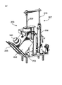
図2と図7に示されているように、配送ユニット200が、密封された過酸化水素溶液ボトル180を受け入れるためのボトルホルダ202を含む。このホルダは、ボトル180が中にぴったりと受け入れられるボトル座204を有する。より詳細に後述されるボトル180は重力だけによって座204内に保持される。ホルダ202は、ボトル180がホルダの中に入れられるか又はホルダから取り外されることが可能な図7に示されている開放位置と、ホルダが完全に滅菌装置キャビネット(図示されていない)内にありかつホルダの前部カバー205がキャビネット外側からのホルダへのアクセス全てを遮る閉鎖位置との間を動くように、ピボット203上に回転自在に取り付けられている。ホルダ202が閉鎖位置にある時には、この実施形態では垂直方向に方向配置された空気圧シリンダ208である針駆動装置と、そのシリンダのピストン棒210上に取り付けられている排液針208とを含む、空気圧で駆動される排液装置207が、ボトル180の底部から過酸化水素溶液全てを排液するために起動される。これは、ボトル180の底部に針の先端が達するまで針209をボトルのシールの中を貫通させるようにシリンダ208を作動させることによって実現される。針209はリザーバ240に流体的に連結されており(図8を参照されたい)、及び、リザーバ240が導管211と弁212によってそれに流体的に連結されることが可能な真空ポンプ44(図1を参照されたい)によって発生させられる真空を使用することによって、その溶液がボトル180からリザーバ240内に吸引される。ボトル180の内容物が吸引され終わると、ホルダが開かれてボトルが取り外されることが可能であり、又は、空のボトルが、リザーバ240の補充が必要とされるまでホルダ内に保持されることが可能である。リザーバ240は、リザーバ内の液位に関する信号を制御システムに提供する液面センサ242を備えている。センサ242から受け取られる信号に基づいて、制御システムは、リザーバ240内の液体の量がユーザによって選択されたサイクルの実行のために不十分であるかどうかを、ユーザに知らせる。
As shown in FIGS. 2 and 7, the
別の実施形態では、過酸化水素配送システムはリザーバを含まない。この代わりに、ボトル180自体が、水性過酸化水素の急速な分解を防ぐために冷却される(CS−01)。センサ(S14)が、ボトル内に残されている溶液の量を測定する。その溶液が第1の予め選択された高さに達すると、第1の警報がスクリーン上に現れ、及び、より低い第2の予め選択された高さに達すると、オペレータに対してソフトウェアから発生されるメッセージが、もう1回だけの滅菌サイクル#1又は#2が、ボトル内の残留する溶液を使って行われることが可能であるということを明示する。その後で、オペレータは、新しい満杯のボトルをその配送システムに再装填しなければならないだろう。
In another embodiment, the hydrogen peroxide delivery system does not include a reservoir. Instead, the
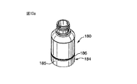
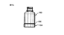
図10aから図10dに示されているように、ボトル180は、そのボトル内の液体全ての完全な排液を確実なものにするために円錐形の底部182を有し、これによって、排液されたボトルの取り外し時における漏出又は汚染の危険性を減少させる。ボトル180が確実に直立状態のままであることを確保するために、スタンド184がボトルの底部末端に取り付けられている。このスタンド184は、ボトルの外側壁187上の円周溝186の中にスナップ嵌めされた上向きのカップ185を含む。針209はボトル底部内の最下点に位置合わせされ、及び、その針がボトル内の最下点に達するまでボトルのシールを貫通してボトルの中に動かされることが可能である。機械式、電子式、又は、他の制御構造及び機能が、ボトル底部の穿孔を防止しながらボトル底部との針の接触を確実なものにするために備えられている。圧力センサが往復針駆動装置及び/又は針マウント(図示されていない)の中に組み込まれることが好ましい。
As shown in FIGS. 10a to 10d, the
制御システム
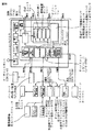
この滅菌装置が、電気ブロック図(図9)及びプロセス流れ図(図3)に示されている方式によって制御されることが好ましい。この制御システムはPLCシェルフ(プログラマブルロジックコントローラ)の周りに構築される。このシェルフは、電源(107)、CPUユニット(108)、デバイスネットトランシーバ(109)、32×24ボルトDCディスクリート入力モジュール(110)、16×120VACディスクリート出力モジュール(111)、最後に16トランジスタディスクリート出力モジュール(112)、及び、RS232C通信モジュールを含む。これらのモジュールの全てが、データ及びアドレスバスを含む組込み接続システム(intrinsic connecting system)によって互いに一体的にスタックされている。
Control System The sterilizer is preferably controlled by the scheme shown in the electrical block diagram (FIG. 9) and process flow diagram (FIG. 3). This control system is built around a PLC shelf (programmable logic controller). This shelf consists of a power supply (107), a CPU unit (108), a device net transceiver (109), a 32 × 24 volt DC discrete input module (110), a 16 × 120 VAC discrete output module (111) and finally a 16 transistor discrete output. A module (112) and an RS232C communication module are included. All of these modules are stacked together on one another by an intrinsic connecting system that includes a data and address bus.
デバイスネットは、計測及び制御のために産業において広く使用されている産業用のシリアル通信プロトコルである。この滅菌装置では、デバイスネットトランシーバ(109)が、CPU(109)と15ビットA/Dコンバータ(106)と15ビットD/Aコンバータ(125)と両方のディジタル温度インターフェース(120)、(121)との間でデータを全二重方式で通信するために使用されている。 The device net is an industrial serial communication protocol widely used in the industry for measurement and control. In this sterilizer, the device net transceiver (109) includes both a CPU (109), a 15-bit A / D converter (106), a 15-bit D / A converter (125), and digital temperature interfaces (120), (121) Is used to communicate data in full duplex.
PLC CPUは3つのRS232ポートを有する。1つは、タッチスクリーンターミナル(118)に対してデータを送受信するために使用され、別の1つは感熱式プリンタ(119)にデータを送るために使用され、最後のポートはサービスポートとして使用され、このサービスポートでは、PC(パーソナルコンピュータ)が、制御プロトコルプログラムをアップロードするためにPLC CPU(108)と通信するために接続されることが可能である(制御プロトコルプログラムはこの文書の範囲内には含まれていない)。 The PLC CPU has three RS232 ports. One is used to send and receive data to the touch screen terminal (118), the other is used to send data to the thermal printer (119) and the last port is used as a service port In this service port, a PC (personal computer) can be connected to communicate with the PLC CPU (108) to upload the control protocol program (the control protocol program is within the scope of this document). Not included).
タッチスクリーンターミナル(118)は、感熱式プリンタ(119)の近くにおいて滅菌装置の前部に配置されている。タッチスクリーンターミナルと感熱式プリンタとがユーザインタフェースターミナルを構成する。 The touch screen terminal (118) is located in front of the sterilizer near the thermal printer (119). The touch screen terminal and the thermal printer constitute a user interface terminal.
感熱式プリンタ(119)とデバイスネットリンク(109)、(106)、(120)、(121)、(125)と、チャンバ圧力センサ(104)と、電子式酸素調整器(126)と、PLCディスクリート入力(111)及びディスクリート出力(112“とに必要な電力が、直流電源(103)によって供給される。 Thermal printer (119), device net link (109), (106), (120), (121), (125), chamber pressure sensor (104), electronic oxygen regulator (126), PLC Electric power necessary for the discrete input (111) and the discrete output (112 "is supplied by the DC power source (103).
チャンバ圧力センサ(104)とオゾン監視装置(105)とが、標準的な0−10VDC出力信号を有する。電子式酸素調整器は、0−5VDCの出力を有する。全ての信号が15ビットA/Dコンバータに送られる。全ての変換された信号が、処理のために、デバイスネットディジタルリンクによってCPUに送られる。 The chamber pressure sensor (104) and the ozone monitor (105) have a standard 0-10 VDC output signal. The electronic oxygen regulator has an output of 0-5 VDC. All signals are sent to a 15-bit A / D converter. All converted signals are sent to the CPU via a device net digital link for processing.
滅菌装置の電力入力(100)は、中性点なしの3ワイヤ208−240VAC単相タイプである。電力入力は、伝導RFIを防止するためにフィルタリングされる(101)。電力は電力配送バス(102)によって滅菌装置の様々な電気システムに分配される。 The power input (100) of the sterilizer is a 3-wire 208-240 VAC single phase type with no neutral point. The power input is filtered (101) to prevent conducted RFI. Power is distributed to the various electrical systems of the sterilizer by a power distribution bus (102).
冷却システム(60)が、オゾン発生器を冷却するために使用される。このシステムは、冷却ユニット(114)と冷却剤循環装置ポンプ(113)とを含む。オゾン発生器内の冷却剤の温度が、オゾン発生器に配置されているRTDによって検出される。この温度は、デバイスネットシステム(109)(120)(121)によってCPU(108)に送られる。冷却剤循環装置(113)と冷却ユニット(114)は、ソフトウェアプロトコルによって制御されるPLC出力(111)によって駆動される接触器(contactor)によって制御される。冷却システムの制御を実現するために必要とされる全ての入力と出力とが、循環装置ポンプリレー、冷却システムリレー、循環装置過負荷センサ、冷却システム過負荷システム、冷媒低圧力及び冷却剤流れスイッチとして、電気ブロック図に示されている。 A cooling system (60) is used to cool the ozone generator. The system includes a cooling unit (114) and a coolant circulator pump (113). The temperature of the coolant in the ozone generator is detected by an RTD located in the ozone generator. This temperature is sent to the CPU (108) by the device network system (109) (120) (121). The coolant circulation device (113) and the cooling unit (114) are controlled by a contactor driven by a PLC output (111) controlled by a software protocol. All inputs and outputs required to achieve control of the cooling system are circulating pump relay, cooling system relay, circulating system overload sensor, cooling system overload system, refrigerant low pressure and coolant flow switch As shown in the electrical block diagram.
真空制御システムは真空ポンプ40と圧力センサ104を含む。真空ポンプの始動及び停止操作が制御プロトコルにしたがって制御される。真空システムに必要とされる全ての入力と出力が、真空ポンプ接触器、真空ポンプ停止センサ(vacuum pump not running sensor)、真空ポンプ過負荷センサ、真空−チャンバ弁(vacuum to chamber valve)(44)、空気パルス弁(18)、及び、酸素−チャンバ弁(oxygen to chamber valve)(21)として、図に示されている。圧力センサの出力は15ビットA/Dコンバータ(106)によって変換され、及び、デバイスネットディジタルリンク(109)によってCPUに送られる。圧力センサは、さらに、温度におけるチャンバ圧力センサ、及び、チャンバ圧力センサヒータ故障という条件をCPU(108)に示す2つの別個の出力を有する。これら2つの信号は、PLC入力として電気ブロック図に示されている。
The vacuum control system includes a
滅菌チャンバ扉作動装置システムは、スクリュー式の電気駆動装置と、制御プロトコルの一部分として扉の閉鎖と作動装置のロック位置とロック解除位置との検出を可能にする4つの誘導センサとを含む。扉開放システムも、ユーザの安全性を確保するために、警報条件管理プロトコルで使用される。扉作動装置システムを実現するために必要とされる全ての入力と出力が、ロック扉リレー(lock door relay)、ロック解除扉リレー(unlock door relay)、扉閉鎖下部センサ(door closed lower sensor)(S2)、扉閉鎖上部センサ(door closed upper sensor)(S1)、扉ロックセンサ(door locked sensor)(S4)、扉ロック解除センサ(door unlocked sensor)(S3)として電気ブロック図に示されている。 The sterilization chamber door actuator system includes a screw-type electric drive and four inductive sensors that allow detection of door closing and actuator locking and unlocking positions as part of the control protocol. The door opening system is also used in the alarm condition management protocol to ensure user safety. All inputs and outputs required to implement a door actuator system are: lock door relay, unlock door relay, door closed lower sensor ( S2), door closed upper sensor (S1), door locked sensor (S4), door unlocked sensor (door unlocked sensor) (S3). .
オゾン電源(116)は、全波整流器と、発振器回路と、高圧変圧器とを含む。この変圧器の出力がオゾン発生器(22)に接続されている。電源(116)は、高圧変圧器の非理想的な特性を使用する共振器として取り付けられている。CPU 108はオゾン発生を制御し、及び、オゾン監視装置104と電子式酸素調整器(126)とによって、滅菌のために求められている濃度が滅菌サイクル全体を通じて実現されかつ維持されることを確実なものにする。オゾン発生システムによって必要とされる全ての入力と出力とが、酸素供給弁(26)、オゾン−チャンバ弁(29a)、オゾン投棄−触媒弁(ozone dump to catalyst valve)(29b)、オゾン監視装置ゼロ設定(ozone monitor zeroing)、高電圧スタンバイリレー、高電圧電流リミタ、オゾン高電圧過負荷センサ、発振器高温度センサ、オゾン監視装置故障として、図に示されている。 The ozone power source (116) includes a full wave rectifier, an oscillator circuit, and a high voltage transformer. The output of this transformer is connected to the ozone generator (22). The power supply (116) is mounted as a resonator that uses the non-ideal characteristics of a high voltage transformer. CPU 108 controls ozone generation and ensures that the concentration required for sterilization is achieved and maintained throughout the sterilization cycle by ozone monitor 104 and electronic oxygen regulator (126). Make things. All inputs and outputs required by the ozone generation system are oxygen supply valve (26), ozone-chamber valve (29a), ozone dump-catalyst valve (29b), ozone monitoring device. Ozone monitor zeroing, high voltage standby relay, high voltage current limiter, ozone high voltage overload sensor, oscillator high temperature sensor, ozone monitor failure is shown in the figure.
オゾン供給システムは、電子式酸素圧力調整器と呼ばれるユニットである。酸素を遮断する比例弁(proportional valve)が、絶対圧力センサ(27)からのアナログ信号を変換する集積PID回路によって制御される。その次に、PIDは適切なデューティサイクル電流を比例弁(26)に送る。オリフィス28と共に、このシステムは酸素流量調整器を構成する。機械式調整器24が、60psiの酸素圧力を10psiに低下させるための第1段の調整器として使用される。この電子式調整器は、さらに、ユーザの保護を確実にするための警報条件プロトコルを提供する。警報条件のために使用される入力が、酸素高圧力センサと酸素低圧力センサとして電気ブロック図に示されている。さらに、電子式酸素圧力調整器は、デバイスネットネットワークを経由してA/Dコンバータ106によって読み取られる0−5VDCアナログ出力を提供した。
The ozone supply system is a unit called an electronic oxygen pressure regulator. A proportional valve that shuts off oxygen is controlled by an integrated PID circuit that converts the analog signal from the absolute pressure sensor (27). The PID then sends the appropriate duty cycle current to the proportional valve (26). Together with the
この制御システムはユーザインタフェース118を備えている。好ましい実施形態では、このインタフェースは、タッチセンシティブ液晶ディスプレイ(LCD)スクリーン118、動作報告のためのプリンタ119、及び、その装置の使用のために必要な情報をユーザが送受信することを可能にする通信ポート153(シリーズRS−232)を含む。タッチセンシティブパッド、キーボード等と、他のタイプの通信インタフェースのような、他のタイプのユーザインタフェースが使用可能であるということが当業者には容易に明らかだろう。感熱プリンタ状態入力が、プリンタオフラインセンサとプリンタ紙切れとして電気ブロック図に示されている。 This control system includes a user interface 118. In the preferred embodiment, this interface includes a touch-sensitive liquid crystal display (LCD) screen 118, a printer 119 for operational reporting, and communications that allow the user to send and receive information necessary for use of the device. Includes port 153 (series RS-232). It will be readily apparent to those skilled in the art that other types of user interfaces can be used, such as touch sensitive pads, keyboards, etc., and other types of communication interfaces. The thermal printer status input is shown in the electrical block diagram as a printer offline sensor and a printer out of paper.
H2O2計量配分システムの制御プロセス
現時点では、H2O2計量配分システムの2つの形状構成が想定可能である。制御システムはこの両方のシステムのために使用可能である。図7と図8において本明細書において説明されている第1のシステムが、主として、図8の温度調整リザーバ(240)の中に流入させられるH2O2のボトル(180)である。この第1のシステムは、図7、図8、図9、図2を参照して説明されるだろう。以下で説明される全ての入力及び出力センサは、図9に示されている制御システムの入力及び出力のリストに示されている。滅菌装置が最初に初期化されると、扉12が閉じられ、及び、この閉じ状態がスイッチS7によって検出される。ホルダ内にボトルがないことが(S6)によって検出されると、穿孔針もシリンダPA−01(208)によって上方位置に引っ込められる。S8とS9とがシリンダ(208)の上方位置及び下方位置の検出を可能にする。さらに、アクチュエータPA−02がホルダロック解除位置に引っ込められる。ユーザは、扉(205)を開いてH2O2ボトルをホルダ内に挿入するように、スクリーン(118)上のメッセージによって促される。したがって、ボトルがS6によって検出されると、スクリーン(118)上の別のメッセージが、S7によって検出される扉(205)を閉じるようにユーザに促す。ソフトウェア制御がCPU(108)と状態センサとによって行われる。ボトルは重力によって回転台(209)上に据えられる。CPUはモータM−02がボトル180を回転させることを開始させる。バーコードリーダBS−01(図2)(122)図9が、ボトル上のバーコードを読み取る。CPUはそのボトルの有効期限を確認し、そのボトルがその有効期限を過ぎている場合には、扉205がロック解除されたままであり、スクリーン(118)上のメッセージが、そのボトルを別のボトルに交換するようにユーザに促す。その有効期限が適正である場合には、CPUは、モータM−02を停止させ、PA−02(図2)を作動させることによって扉(205)をロックする。その次に、CPUは、S9が針が下方位置にあることを検出するまで、針209がボトルの密封キャップに穿孔するようにシリンダ(208)を作動させる。その次に、ボトルが、弁(212)を経由した吸引とポンプ(40)からの真空とによって、リザーバ240の中に中身を送り込まれて完全に空にされる。リザーバ内のH2O2全てが使用され終わるまで扉(205)はロックされたままである。液位センサS10、S11が、別のボトルが必要かどうかをCPUが推定するために必要な状態を提供する。そうである場合には、針がボトルから引き戻されて、扉(205)がロック解除され、及び、ユーザがH2O2ボトルを交換するようにスクリーン(118)上のメッセージによって促される。
Control process of the H2O2 metering system At present, it is possible to envisage two configurations of the H2O2 metering system. The control system can be used for both systems. The first system described herein in FIGS. 7 and 8 is primarily a H2O2 bottle (180) that is flowed into the temperature regulating reservoir (240) of FIG. This first system will be described with reference to FIGS. 7, 8, 9, and 2. FIG. All input and output sensors described below are shown in the control system input and output list shown in FIG. When the sterilizer is first initialized, the
別の好ましいH2O2計量配分システムの説明
次に述べる計量配分システムは、冷却されたリザーバ(240)を含まない。その代わりに、H2O2はボトル(180)内に残る。液位検出器S10、S11が取り除かれ、及び、底部の付近においてボトルの側部に対してばねで押し付けられている超音波液位検出器によって置き換えられており、及び、この超音波液位検出器は、CPUに対して空のボトルを示すための低液位検出器として使用される。このセンサがばねで押し付けられているので、このセンサは、モータM−02を使用するには大きすぎる摩擦をボトル上に加える。したがって、ユーザは、バーコードが(BS−01)図2又は(122)図9によって読み取られるまで、ボトルを手動で回転させるように、スクリーン(118)上のメッセージによって促される。ボトルが期限切れではない場合には、ユーザは扉(205)を閉じるように促され、及び、CPUがボトルホルダのコンパートメントをロックし、及び、針を下降させて穿孔させるように作動させる(208)。その好ましい実施形態では、H2O2ホルダはペルチェセルユニットによって温度調整されている。ホルダに取り付けられておりかつ温度インタフェース(121)に接続されているRTDが、デバイスネットネットワークによってCPU(108)にデータを送り、及び、CPUは、ペルチェセルユニットに印加される電力の量をPID機能によって制御する。ペルチェユニットは、図2においてSV−15、SV−16、アクチュエータ(PA−02及びPA−01)で構成されている空気圧システムを駆動する空気圧縮機のためにも使用される12VDC(121)電源によって給電される。各サイクルの間には、H2O2ボトル(180)とマイクロバルブモジュール(240)との間に連結されている配管がSV20によってパージされるだろう。モジュール(240)の入口の付近では、H2O2配管上にスナップ留めされている泡光学検出器(foam optical detector)が、その配管内の、空気無しでのその配管の完全な補充を表示するだろう。
Description of Another Preferred H2O2 Metering System The metering system described below does not include a cooled reservoir (240). Instead, H2O2 remains in the bottle (180). The liquid level detectors S10, S11 have been removed and replaced by an ultrasonic liquid level detector which is pressed against the side of the bottle in the vicinity of the bottom, and this ultrasonic liquid level detection. The instrument is used as a low liquid level detector to indicate an empty bottle to the CPU. Since this sensor is pressed by a spring, this sensor adds too much friction on the bottle to use the motor M-02. Thus, the user is prompted by a message on the screen (118) to manually rotate the bottle until the barcode is read by (BS-01) FIG. 2 or (122) FIG. If the bottle has not expired, the user is prompted to close the door (205) and the CPU is activated to lock the bottle holder compartment and lower the needle to pierce (208). . In its preferred embodiment, the H2O2 holder is temperature controlled by a Peltier cell unit. The RTD attached to the holder and connected to the temperature interface (121) sends data to the CPU (108) via the device net network, and the CPU PID determines the amount of power applied to the Peltier cell unit. Control by function. The Peltier unit is a 12VDC (121) power supply that is also used for the air compressor that drives the pneumatic system consisting of SV-15, SV-16, actuators (PA-02 and PA-01) in FIG. Is powered by. Between each cycle, the tubing connected between the H2O2 bottle (180) and the microvalve module (240) will be purged by the SV20. Near the entrance of the module (240), a foam optical detector snapped onto the H2O2 pipe will indicate a complete refill of that pipe in the pipe without air. .
この点までは、両方のH2O2計量配分システムがマイクロバルブモジュール(240)に供給することが可能である。マイクロバルブ(SV−18及びSV19)は、両方のマイクロ弁のための適正なタイミングパルスを発生させるオンボードのマイクロコントローラ回路上のプリセットされたデューティサイクルプログラムのために相反的に動作している。この電子回路は、H2O2ポンプコントローラ信号(図9)と呼ばれるCPU(108)からの信号によって作動させられる。ソフトウェアの制御を受けて、適正な量のH2O2が加湿器マニホルド(260、図1)の中に受け入れられる。このマニホルドは、RTD(TT−04、図1)のデータを使用しかつPID機能によって加熱器HTR−01(図1)を制御するCPU(108)によって温度制御されている。その次に、H2O2がそのマニホルド(260)内で蒸発し、その蒸気はパイプ(280、図1)を通して真空下でチャンバに送られる。 Up to this point, both H2O2 metering systems can feed the microvalve module (240). The microvalves (SV-18 and SV19) are operating reciprocally for a preset duty cycle program on the onboard microcontroller circuit that generates the proper timing pulses for both microvalves. This electronic circuit is activated by a signal from the CPU (108) called the H2O2 pump controller signal (FIG. 9). Under software control, the proper amount of H2O2 is received in the humidifier manifold (260, FIG. 1). The manifold is temperature controlled by a CPU (108) that uses RTD (TT-04, FIG. 1) data and controls the heater HTR-01 (FIG. 1) by the PID function. Then H2O2 evaporates in the manifold (260) and the vapor is sent to the chamber under vacuum through the pipe (280, FIG. 1).
上述の記述内容では、説明のために、本発明の実施形態の完全な理解を実現するように、数多くの詳細事項が明記されている。しかし、これらの個別的な詳細事項が本発明を実施するために必ずしも必要であるわけではないということが、当業者には明らかだろう。他の例では、公知の滅菌装置の構造と回路とが、本発明を不明瞭にしないために、ブロック図又は記号形式(symbol form)で示されている。例えば、滅菌装置の制御装置の特定の部分がソフトウェアルーチン、ハードウェア回路、ファームウェア、又は、これらの組み合わせとして具体化されているかどうかに関して、個別的な詳細事項が示されていない。 In the description above, for the purposes of explanation, numerous specific details are set forth in order to provide a thorough understanding of the embodiments of the invention. However, it will be apparent to those skilled in the art that these specific details are not necessarily required to practice the invention. In other instances, the structure and circuitry of known sterilizers are shown in block diagram or symbol form so as not to obscure the present invention. For example, specific details are not provided as to whether a particular portion of the sterilizer controller is embodied as a software routine, hardware circuit, firmware, or a combination thereof.
本発明の上述の実施形態は単なる例示にすぎないことが意図されている。本発明の範囲から逸脱することなしに、当業者によって、これらの特定の実施形態に対して改変と変更と変形とが加えられることが可能であり、本発明の範囲は、本明細書に添付されている特許請求項だけによって定義されている。
10 滅菌チャンバ
12 アクセス扉
22 オゾン発生器
29b バイパス弁
30 過酸化水素配送ユニット
40 真空ポンプ
52 オゾン触媒
60 冷却システム
200 過酸化水素供給ユニット
220 リザーバ
240 計量供給ユニット
260 蒸発器ユニット
DESCRIPTION OF
Claims (3)
前記予め選択された温度で過酸化水素が沸騰する圧力よりも低い真空圧に前記滅菌チャンバを維持する段階と、
過酸化水素の連続パルスを蒸発させる段階と、
前記蒸発した過酸化水素を前記チャンバ内に注入し、これによって過酸化水素の各パルスの体積が75μL未満である段階とを含む方法。 In a method for inhibiting undesired condensation of hydrogen peroxide in a sterilization chamber at a preselected temperature,
Maintaining the sterilization chamber at a vacuum pressure lower than the pressure at which hydrogen peroxide boils at the preselected temperature;
Evaporating a continuous pulse of hydrogen peroxide;
Injecting the evaporated hydrogen peroxide into the chamber, whereby the volume of each pulse of hydrogen peroxide is less than 75 μL.
Applications Claiming Priority (2)
| Application Number | Priority Date | Filing Date | Title |
|---|---|---|---|
| US24719709P | 2009-09-30 | 2009-09-30 | |
| US61/247,197 | 2009-09-30 |
Related Parent Applications (1)
| Application Number | Title | Priority Date | Filing Date |
|---|---|---|---|
| JP2012531191A Division JP5480975B2 (en) | 2009-09-30 | 2010-09-29 | Sterilization method and apparatus |
Related Child Applications (1)
| Application Number | Title | Priority Date | Filing Date |
|---|---|---|---|
| JP2015238619A Division JP6141950B2 (en) | 2009-09-30 | 2015-12-07 | Sterilization method and apparatus |
Publications (2)
| Publication Number | Publication Date |
|---|---|
| JP2013144159A true JP2013144159A (en) | 2013-07-25 |
| JP5855045B2 JP5855045B2 (en) | 2016-02-09 |
Family
ID=43780606
Family Applications (8)
| Application Number | Title | Priority Date | Filing Date |
|---|---|---|---|
| JP2012531191A Expired - Fee Related JP5480975B2 (en) | 2009-09-30 | 2010-09-29 | Sterilization method and apparatus |
| JP2013083152A Active JP5785208B2 (en) | 2009-09-30 | 2013-04-11 | Sterilization method and apparatus |
| JP2013083154A Active JP5785209B2 (en) | 2009-09-30 | 2013-04-11 | Hydrogen peroxide sterilization method |
| JP2013083238A Active JP5785211B2 (en) | 2009-09-30 | 2013-04-11 | Sterilizer |
| JP2013083146A Active JP5785207B2 (en) | 2009-09-30 | 2013-04-11 | Hydrogen peroxide sterilization method |
| JP2013083229A Active JP5785210B2 (en) | 2009-09-30 | 2013-04-11 | Hydrogen peroxide sterilization method |
| JP2013083142A Expired - Fee Related JP5855045B2 (en) | 2009-09-30 | 2013-04-11 | Sterilization method and apparatus |
| JP2015238619A Expired - Fee Related JP6141950B2 (en) | 2009-09-30 | 2015-12-07 | Sterilization method and apparatus |
Family Applications Before (6)
| Application Number | Title | Priority Date | Filing Date |
|---|---|---|---|
| JP2012531191A Expired - Fee Related JP5480975B2 (en) | 2009-09-30 | 2010-09-29 | Sterilization method and apparatus |
| JP2013083152A Active JP5785208B2 (en) | 2009-09-30 | 2013-04-11 | Sterilization method and apparatus |
| JP2013083154A Active JP5785209B2 (en) | 2009-09-30 | 2013-04-11 | Hydrogen peroxide sterilization method |
| JP2013083238A Active JP5785211B2 (en) | 2009-09-30 | 2013-04-11 | Sterilizer |
| JP2013083146A Active JP5785207B2 (en) | 2009-09-30 | 2013-04-11 | Hydrogen peroxide sterilization method |
| JP2013083229A Active JP5785210B2 (en) | 2009-09-30 | 2013-04-11 | Hydrogen peroxide sterilization method |
Family Applications After (1)
| Application Number | Title | Priority Date | Filing Date |
|---|---|---|---|
| JP2015238619A Expired - Fee Related JP6141950B2 (en) | 2009-09-30 | 2015-12-07 | Sterilization method and apparatus |
Country Status (15)
| Country | Link |
|---|---|
| US (11) | US9101679B2 (en) |
| EP (9) | EP2601978B1 (en) |
| JP (8) | JP5480975B2 (en) |
| KR (8) | KR101827462B1 (en) |
| AU (1) | AU2010302888B2 (en) |
| BR (7) | BR122013010296A2 (en) |
| CA (7) | CA2808561C (en) |
| ES (8) | ES2531976T3 (en) |
| HK (3) | HK1185818A1 (en) |
| MX (7) | MX351399B (en) |
| PL (3) | PL2601979T3 (en) |
| PT (1) | PT3056224T (en) |
| TR (1) | TR201900045T4 (en) |
| WO (1) | WO2011038487A1 (en) |
| ZA (1) | ZA201201389B (en) |
Cited By (4)
| Publication number | Priority date | Publication date | Assignee | Title |
|---|---|---|---|---|
| JP2016533836A (en) * | 2013-09-06 | 2016-11-04 | ティーエスオースリー インコーポレイティド | Sterilization method and apparatus and adaptive control thereof |
| JP2017012400A (en) * | 2015-06-30 | 2017-01-19 | 株式会社大林組 | Decontamination method and decontamination system |
| JP2018064942A (en) * | 2016-10-21 | 2018-04-26 | エシコン・インコーポレイテッドEthicon, Incorporated | Dynamic dosage of disinfectant agent with concentrate degradation compensation |
| US10709803B2 (en) | 2013-09-06 | 2020-07-14 | Ts03 Inc. | Sterilization apparatus and adaptive control thereof |
Families Citing this family (112)
| Publication number | Priority date | Publication date | Assignee | Title |
|---|---|---|---|---|
| USRE47582E1 (en) | 2009-07-28 | 2019-08-27 | Sterifre Medical, Inc. | Free radical sterilization system and method |
| KR101827462B1 (en) * | 2009-09-30 | 2018-02-09 | 떼에스오뜨로와 이엔쎄. | Hydrogen peroxide metering unit for hydrogen peroxide sterilizer |
| US8889081B2 (en) | 2009-10-15 | 2014-11-18 | Medivators Inc. | Room fogging disinfection system |
| EP2586465B1 (en) | 2009-12-03 | 2014-04-23 | Minntech Corporation | System for decontaminating a medical device with a fog |
| CN102178968B (en) * | 2011-04-26 | 2014-02-26 | 中国人民解放军军事医学科学院卫生装备研究所 | Chlorine dioxide gas disinfection device |
| WO2012173756A1 (en) * | 2011-05-27 | 2012-12-20 | Minntech Corporation | Decontamination system including environmental control using a decontaminating substance |
| US10434204B2 (en) | 2011-07-15 | 2019-10-08 | Soclean, Inc. | Technologies for sanitizing mist humidifiers |
| EP2731632B1 (en) | 2011-07-15 | 2017-08-30 | SoClean, Inc. | CPAP device with ozone generator |
| ITMI20111507A1 (en) | 2011-08-05 | 2013-02-06 | Absolute Up S R L | STEAM STERILIZER |
| CN104159734B (en) * | 2011-08-15 | 2017-11-21 | 纳幕尔杜邦公司 | For protecting the ventilative product of bulk transport and cold chain purposes |
| US8641985B2 (en) * | 2011-08-25 | 2014-02-04 | Tuttnauer Ltd. | Control system for ozone sterilization in multiple compact chambers |
| WO2013040415A1 (en) * | 2011-09-16 | 2013-03-21 | The Trustees Of The University Of Pennsylvania | Rapid surface disinfection method and apparatus |
| JP5668666B2 (en) * | 2011-10-31 | 2015-02-12 | キヤノンマーケティングジャパン株式会社 | Sterilizer, sterilization method |
| KR101324567B1 (en) | 2011-10-28 | 2013-11-01 | 주식회사 리노셈 | Method for sterilizing medical instrument |
| DE102011056438A1 (en) * | 2011-12-14 | 2013-06-20 | Krones Ag | Evaporator device, beverage bottling plant and / or beverage container manufacturing plant, method for operating an evaporator device and use of a sterilization mixture-discharge device |
| ITMI20112334A1 (en) * | 2011-12-21 | 2013-06-22 | Absolute Up S R L | STEAM STERILIZER |
| JP2013158699A (en) * | 2012-02-03 | 2013-08-19 | Ihi Shibaura Machinery Corp | Oxidation treatment method, and oxidation treatment system |
| US20130251863A1 (en) * | 2012-03-20 | 2013-09-26 | The Ohio State University Research Foundation | Apparatus for Treating Items with Gas |
| MX2014011521A (en) * | 2012-03-28 | 2015-01-16 | Rasirc Inc | Method of delivering a process gas from a multi-component solution. |
| US20130294969A1 (en) * | 2012-05-02 | 2013-11-07 | Nellcor Puritan Bennett Llc | Wireless, Reusable, Rechargeable Medical Sensors and System for Recharging and Disinfecting the Same |
| CN102671225B (en) * | 2012-05-28 | 2015-08-26 | 上海东富龙爱瑞思科技有限公司 | A kind of hydrogen peroxide vapor sterilization device |
| US9459233B2 (en) | 2012-06-25 | 2016-10-04 | Steris Corporation | Amperometric gas sensor |
| JP6253223B2 (en) * | 2012-07-25 | 2017-12-27 | 株式会社Ihi | Sterilizer |
| DE102012018109A1 (en) * | 2012-09-04 | 2014-03-27 | Linde Aktiengesellschaft | Method for carrying out a pressure test on a tank and refueling device |
| JP5943102B2 (en) * | 2012-12-13 | 2016-06-29 | キヤノンマーケティングジャパン株式会社 | Sterilizer, sterilization method, program |
| JP5696740B2 (en) * | 2012-12-13 | 2015-04-08 | キヤノンマーケティングジャパン株式会社 | Sterilizer, sterilization method, program |
| CN103041417A (en) * | 2013-01-30 | 2013-04-17 | 杭州盈天科学仪器有限公司 | Transfer cabin with sterilization function |
| WO2014133854A1 (en) | 2013-02-26 | 2014-09-04 | 3M Innovative Properties Company | Biological indicator for monitoring a low-temperature sterilization process |
| KR101469943B1 (en) * | 2013-03-25 | 2014-12-09 | (주)푸르고팜 | ClO2 GAS FUMIGATION APPARATUS, AND FUMIGATATION METHOD BY THE SAME |
| US9789217B2 (en) | 2013-04-30 | 2017-10-17 | Helder GONCALVES DA COSTA | Packaging and transportation kit for hydrogen peroxide or other chemical product used in sterilization or disinfection equipments and respective supplying system |
| KR101465563B1 (en) * | 2013-08-26 | 2014-11-26 | (주)옥시테라피 | Using the wet gaseous chlorine-dioxide sterilization device and sterilization methods |
| US9302021B2 (en) * | 2013-08-30 | 2016-04-05 | American Sterilizer Company | Method of performing sterilization cycle |
| GB2518239A (en) | 2013-09-17 | 2015-03-18 | Tristel Plc | Decontamination System |
| BR102013030702B1 (en) * | 2013-11-28 | 2019-12-24 | Cisabrasile Ltda | vacuum system for sterilization equipment without using unlimited water to saturated steam |
| EP3116553B1 (en) | 2014-03-09 | 2022-09-28 | Lynch, Edward | Disinfection apparatus |
| CN103920176B (en) * | 2014-04-25 | 2018-08-31 | 上海净达制药设备系统工程有限公司 | It ionizes hydrogen peroxide and integrates plasma sterilization technology |
| US20150305344A1 (en) * | 2014-04-28 | 2015-10-29 | American Sterilizer Company | Decontamination or sterilization process |
| US10463754B2 (en) | 2014-04-28 | 2019-11-05 | American Sterilizer Company | Process for decontaminating or sterilizing an article |
| US10869479B2 (en) | 2014-04-28 | 2020-12-22 | American Sterilizer Company | Wipe for killing spores |
| US9907872B2 (en) | 2014-05-06 | 2018-03-06 | Soclean, Inc. | Devices, systems and methods for ozone sanitization of continuous positive airway pressure devices |
| SG11201609469XA (en) | 2014-05-13 | 2016-12-29 | Rasirc Inc | Methods and systems for delivering process gases to critical process applications |
| EP2952474A1 (en) * | 2014-06-03 | 2015-12-09 | Steris Europe, Inc. Suomen Sivuliike | Method and device for generating steam and gaseous hydrogen peroxide |
| CN104190686A (en) * | 2014-07-01 | 2014-12-10 | 栖霞中泰环保设备有限公司 | Pre-vacuum suction mechanism of medical waste treatment equipment |
| CN104083787B (en) * | 2014-07-09 | 2017-01-25 | 张家港市嘉瑞制药机械有限公司 | Ethanol sterilizer |
| WO2016025934A1 (en) * | 2014-08-15 | 2016-02-18 | The United States Of America As Represented By The Secretary Of The Navy | Self-contained portable ozone sterilizer for small medical equipment |
| DE112014007093B4 (en) * | 2014-10-22 | 2019-05-02 | Helder da Costa Goncalves | STERILIZATION DEVICE USING HYDROGEN PEROXIDE AND OZONE THAT IS EXPRESSED AND COMBINED BY SEVERAL CAPILLARY TUBES |
| US10150048B2 (en) | 2014-10-23 | 2018-12-11 | Rasirc, Inc. | Method, system, and device for delivery of process gas |
| JP6272214B2 (en) | 2014-12-02 | 2018-01-31 | 三菱重工機械システム株式会社 | Container sterilization method and sterilization system |
| WO2016086299A1 (en) * | 2014-12-03 | 2016-06-09 | Tso3 Inc. | Method for establishing resistance characteristics of a biological indicator |
| JP6520112B2 (en) * | 2014-12-24 | 2019-05-29 | キヤノンマーケティングジャパン株式会社 | Sterilizer and control method thereof |
| KR101653173B1 (en) * | 2015-02-03 | 2016-09-02 | (주) 씨엠테크 | Hydrogen peroxide supply device |
| JP6761563B2 (en) * | 2015-02-20 | 2020-09-30 | 三浦工業株式会社 | Decontamination equipment and decontamination method |
| CN104800874B (en) * | 2015-04-21 | 2017-08-15 | 佛山皓明拓普新材料科技有限公司 | A kind of sterilizing is dispelled taste machine |
| JP6411286B2 (en) * | 2015-06-02 | 2018-10-24 | 日本エアーテック株式会社 | Hydrogen peroxide gas removal device |
| KR101732677B1 (en) * | 2015-10-13 | 2017-05-04 | 주식회사 큐브인스트루먼트 | Low Temperature Sterilizer Having Chamber Of Which Volume Is Variable |
| EP3370782A4 (en) * | 2015-11-02 | 2019-07-24 | Pura Scents, Inc. | Scent dispensation |
| CN108778480B (en) | 2015-12-14 | 2021-09-24 | 山东新华医疗器械股份有限公司 | Liquid supply system and driving method thereof |
| RU2730830C2 (en) * | 2015-12-14 | 2020-08-26 | Сарая Ко., Лтд. | Liquid supply system |
| US20200360552A1 (en) * | 2015-12-18 | 2020-11-19 | Caron Products And Services, Inc. | System and method for vaporized hydrogen peroxide cleaning of contents of a chamber of a container |
| US10039850B2 (en) | 2016-01-13 | 2018-08-07 | Sterio3, Llc | Sterilization device and methods |
| CA3011166C (en) | 2016-01-13 | 2023-07-18 | Sterio3, Llc | Sterilization device and methods |
| FR3046730A1 (en) * | 2016-01-15 | 2017-07-21 | Sidel Participations | METHOD AND DEVICE FOR STERILIZING GAS FILTRATION MEANS, IN PARTICULAR BLOWING AIR |
| WO2017218832A1 (en) | 2016-06-17 | 2017-12-21 | Sterifre Medical Inc. | Sterilization, disinfection, sanitization, decontamination, and therapeutic devices, systems, and methods |
| US10314929B2 (en) | 2016-06-30 | 2019-06-11 | Ethicon, Inc. | Apparatus and method for sterilizing endoscope |
| US11696967B2 (en) | 2016-06-30 | 2023-07-11 | Asp Global Manufacturing Gmbh | Apparatus and method for sterilizing endoscope |
| KR101867904B1 (en) | 2016-08-05 | 2018-06-18 | 한국과학기술연구원 | Evaporator device for sterilant |
| KR101846251B1 (en) * | 2016-08-17 | 2018-04-09 | 주식회사 큐브인스트루먼트 | Method Using Low Temperature Sterilizer Having Chamber of Which Volume Is Variable |
| IL311121A (en) | 2017-03-27 | 2024-04-01 | Regeneron Pharma | Sterilisation method |
| CN108686240B (en) * | 2017-04-10 | 2022-03-04 | 山东新华医疗器械股份有限公司 | Sterilization method and sterilization apparatus |
| KR101985173B1 (en) | 2017-05-08 | 2019-06-04 | 한국과학기술연구원 | Hydrogen peroxide vapor evaporating and detoxifying system |
| US10889848B2 (en) | 2017-07-14 | 2021-01-12 | American Sterilizer Company | Process for determining viability of test microorganisms of biological indicator and sterilization detection device for determining same |
| US10900062B2 (en) | 2017-07-14 | 2021-01-26 | American Sterilizer Company | Process for determining viability of test microorganisms of biological indicator and sterilization detection device for determining same |
| US10876144B2 (en) | 2017-07-14 | 2020-12-29 | American Sterilizer Company | Process for determining viability of test microorganisms of biological indicator and sterilization detection device for determining same |
| KR101899786B1 (en) * | 2017-07-27 | 2018-09-20 | 이승재 | A hpae of attaching driving signal control unit of injection of hydrogen peroxide aerosol |
| WO2019084203A1 (en) | 2017-10-25 | 2019-05-02 | Sterifre Medical Inc. | Devices, systems, and methods for sterilization, disinfection, sanitization and decontamination |
| US11420085B2 (en) | 2017-12-08 | 2022-08-23 | Oshkosh Corporation | Ozone cleaning system |
| CN111491680B (en) | 2017-12-13 | 2023-08-29 | 里珍纳龙药品有限公司 | Device and method for accurate dose delivery |
| KR102114684B1 (en) * | 2017-12-28 | 2020-05-25 | 주식회사 이노켐텍 | Sterilizer |
| JP6607277B2 (en) * | 2018-04-03 | 2019-11-20 | 株式会社三洋物産 | Game machine |
| JP7115139B2 (en) * | 2018-08-23 | 2022-08-09 | 株式会社Ihi | OH radical treatment device and OH radical treatment method |
| US20220117466A1 (en) | 2018-11-30 | 2022-04-21 | Tso3 Inc. | Endoscopes With Improved Compatibility To Oxidative Processings And Methods For Manufacturing And Repairing The Same |
| US11007289B2 (en) | 2019-02-14 | 2021-05-18 | American Sterilizer Company | Method for pressurizing a steam sterilization chamber |
| US10792613B1 (en) * | 2019-03-11 | 2020-10-06 | Oshkosh Corporation | Cleaning device |
| CN113195007A (en) * | 2019-03-14 | 2021-07-30 | 三浦工业株式会社 | Sterilization method and sterilization apparatus |
| US20210196850A1 (en) | 2019-03-19 | 2021-07-01 | Soclean, Inc. | Technologies for sanitizing medical devices |
| JP7163242B2 (en) | 2019-04-17 | 2022-10-31 | Toyo Tire株式会社 | Sulfur cross-linking density evaluation method for polymeric materials |
| MA54325A (en) | 2019-06-05 | 2022-05-11 | Regeneron Pharma | DEVICES AND METHODS FOR ACCURATE DOSE DELIVERY |
| US11291740B2 (en) | 2019-08-12 | 2022-04-05 | Gcmg Companies, Llc | Fogging system and methods for enclosed chambers |
| EP4031208A1 (en) * | 2019-09-16 | 2022-07-27 | Amgen Inc. | Method for external sterilization of drug delivery device |
| CN110448710A (en) * | 2019-09-18 | 2019-11-15 | 好空气科技发展有限公司 | A kind of method of fabric high efficiency disinfection |
| CN110507837A (en) * | 2019-09-18 | 2019-11-29 | 好空气科技发展有限公司 | A kind of vacuum ozone high-effective disinfecting device |
| CA3169039A1 (en) * | 2020-01-28 | 2021-08-05 | Tekdry International, Inc. | Molecular mobility enhancer or molecular drying enhancer |
| CN111150867B (en) * | 2020-02-18 | 2020-12-29 | 青岛大学附属医院 | Needle tube disinfecting equipment |
| KR20220146545A (en) * | 2020-02-26 | 2022-11-01 | 케어퓨젼 코포레이션 | Systems and methods for sterilizing iodophor compositions |
| WO2021192230A1 (en) * | 2020-03-27 | 2021-09-30 | 三浦工業株式会社 | Sterilization method and sterilization device |
| JP2021153912A (en) * | 2020-03-27 | 2021-10-07 | 三浦工業株式会社 | Sterilization method, and sterilization apparatus |
| JP7168081B2 (en) * | 2020-03-27 | 2022-11-09 | 三浦工業株式会社 | Sterilization method and sterilization device |
| JP7468060B2 (en) | 2020-03-27 | 2024-04-16 | 三浦工業株式会社 | Sterilization method and sterilization device |
| CN111392221B (en) * | 2020-04-02 | 2021-09-14 | 上海久正医用包装材料有限公司 | Medicinal packaging bag and production process thereof |
| GB202007453D0 (en) * | 2020-05-19 | 2020-07-01 | Aseptick Ltd | Apparatus and methods for decontaminating enclosed spaces |
| CN111640566B (en) * | 2020-05-20 | 2021-09-21 | 杭州三炻磁性材料有限公司 | Process method for pressing constant-pressure constant-magnetism samarium cobalt powder |
| CN111920971B (en) * | 2020-07-03 | 2022-07-26 | 义乌市宏博机械科技有限公司 | Sterilizing device for regulating and controlling high-temperature water vapor amount according to dead weight of surgical supplies |
| JP2022044329A (en) * | 2020-09-07 | 2022-03-17 | ウシオ電機株式会社 | Sterilization treatment method and sterilization treatment device |
| CA3202930A1 (en) * | 2020-12-21 | 2022-06-30 | Benjamin Fryer | A method and a system for adjusting a cycle time of a treatment process for an object |
| JP2023553087A (en) * | 2020-12-21 | 2023-12-20 | ザ プロクター アンド ギャンブル カンパニー | Method for sterilizing and decontaminating used absorbent hygiene products contaminated with organic compounds derived from human metabolism |
| CN112618757A (en) * | 2020-12-21 | 2021-04-09 | 王铁军 | Medicine bottle sterilizing device |
| CN112972723B (en) * | 2021-02-24 | 2021-11-30 | 西安交通大学 | Discharge plasma disinfection device combining nitrogen oxide mode and ozone mode |
| US20220331470A1 (en) * | 2021-04-08 | 2022-10-20 | Regeneron Pharmaceuticals, Inc. | Methods and systems for sterilization |
| CA3224413A1 (en) * | 2021-07-06 | 2023-01-12 | Boaz Nitzan | Methods for preserving plant matter |
| KR102652622B1 (en) | 2021-11-12 | 2024-03-29 | 주식회사 퓨어텍 | Method and apparatus for sterilization using hydrogen peroxide |
| US20230219034A1 (en) * | 2022-01-12 | 2023-07-13 | Thalo Labs, Inc. | System for capturing emissions |
| KR102589748B1 (en) * | 2023-05-31 | 2023-10-16 | (주)대성하이텍 | Dry type sterilization and disinfection apparatus |
Citations (9)
| Publication number | Priority date | Publication date | Assignee | Title |
|---|---|---|---|---|
| US4956145A (en) * | 1987-12-30 | 1990-09-11 | American Sterilizer Company | Optimum hydrogen peroxide vapor sterilization method |
| JPH06510932A (en) * | 1992-03-13 | 1994-12-08 | アメリカン ステリライザー カンパニー | Sterilization apparatus and method for sterilization agents containing multiple components |
| US5508009A (en) * | 1992-03-13 | 1996-04-16 | American Sterilizer Company | Optimum hydrogen peroxide vapor sterilization system |
| JPH08505787A (en) * | 1992-11-12 | 1996-06-25 | アメリカン ステリライザー カンパニー | How to enhance the penetration of low vapor pressure chemical vapor sterilants during sterilization |
| JP2006204889A (en) * | 2004-03-31 | 2006-08-10 | Yuyama Manufacturing Co Ltd | Method of sterilization and apparatus therefor |
| US20070098591A1 (en) * | 2005-10-31 | 2007-05-03 | Georg Frinke | Method and apparatus for low energy vaporization of liquid oxidizing agents or solutions |
| JP2007518954A (en) * | 2003-12-10 | 2007-07-12 | ステリス インク | Ozone enhanced hydrogen peroxide vapor decontamination method and system |
| JP2010533030A (en) * | 2007-07-10 | 2010-10-21 | エルデル、ダ、コスタ、ゴンカルベス | Method and apparatus for hydrogen peroxide sterilization |
| US20110176959A1 (en) * | 2004-11-26 | 2011-07-21 | Human Meditek Co., Ltd. | Hydrogen peroxide vapor sterilizer and sterilizing methods using the same |
Family Cites Families (85)
| Publication number | Priority date | Publication date | Assignee | Title |
|---|---|---|---|---|
| GB264936A (en) | 1925-10-30 | 1927-01-31 | British Celanese | Improvements in or relating to the treatment of yarns and fabrics |
| GB1324660A (en) * | 1969-09-30 | 1973-07-25 | Sprinter Pack Ab | Container with lid for liquids especially carbonized beverages |
| US3978232A (en) * | 1970-12-30 | 1976-08-31 | Edward Dodsworth | Thin walled containers for pressurized liquids |
| US3880011A (en) * | 1974-02-14 | 1975-04-29 | Harsco Corp | Automatic sampler |
| US4082200A (en) | 1976-06-29 | 1978-04-04 | Owens-Illinois, Inc. | Plastic container with support base, and method of assembly |
| US4300404A (en) * | 1977-12-01 | 1981-11-17 | Becton, Dickinson And Company | Liquid specimen container |
| JPS54163993U (en) * | 1978-05-10 | 1979-11-16 | ||
| FR2427343A1 (en) | 1978-05-31 | 1979-12-28 | Dia Prosim | PROCESS FOR THE BROMATION OF RESINS BASED ON CROSS-LINKED VINYLAROMATIC COPOLYMERS |
| JPS57192067A (en) * | 1981-05-22 | 1982-11-26 | Hitachi Ltd | Erasable and programmable read only memory unit |
| US4434820A (en) * | 1982-05-05 | 1984-03-06 | Glass John P | Syringe loader and method |
| JPS5969077A (en) | 1982-10-12 | 1984-04-19 | アメリカン・ステリライザ−・コムパニ− | Sterilization by hydrogen peroxide liquid film |
| US4548348A (en) * | 1984-02-27 | 1985-10-22 | Solo Cup Company | Disposable cup assembly |
| US4642165A (en) * | 1984-12-21 | 1987-02-10 | American Sterilizer Company | Method of vaporizing multicomponent liquids |
| US5037623A (en) * | 1986-02-06 | 1991-08-06 | Steris Corporation | Sterilant concentrate injection system |
| JPS63246676A (en) * | 1987-03-31 | 1988-10-13 | Shimadzu Corp | Sample introducing apparatus |
| CA1303811C (en) * | 1987-07-06 | 1992-06-23 | Robert W. Childers | Flow-through vapor phase sterilization system |
| US4838887A (en) * | 1987-12-15 | 1989-06-13 | Shiley Infusaid Inc. | Programmable valve pump |
| US4952370A (en) * | 1988-05-06 | 1990-08-28 | American Sterilizer Company | Hydrogen peroxide sterilization method |
| JPH0219742U (en) * | 1988-07-27 | 1990-02-08 | ||
| JPH02301308A (en) | 1989-05-16 | 1990-12-13 | Iwatsu Electric Co Ltd | Gain variable circuit |
| JPH03182658A (en) | 1989-12-13 | 1991-08-08 | Nissan Motor Co Ltd | Control device for internal combustion engine |
| US5122344A (en) * | 1990-01-31 | 1992-06-16 | Mdt Corporation | Chemical sterilizer system |
| JPH0422761A (en) * | 1990-05-17 | 1992-01-27 | Mitsubishi Electric Corp | Ignition device for internal combustion engine and method thereof |
| JPH0454698A (en) | 1990-06-22 | 1992-02-21 | Matsushita Refrig Co Ltd | Commodity storage device for automatic vending machine |
| JP2583804B2 (en) * | 1990-07-17 | 1997-02-19 | 三菱重工業株式会社 | Liquid recovery method for can-shaped containers |
| JPH0698998B2 (en) * | 1990-08-27 | 1994-12-07 | 麒麟麦酒株式会社 | Liquid recovery device in can |
| US5244629A (en) * | 1990-08-31 | 1993-09-14 | Caputo Ross A | Plasma sterilizing process with pulsed antimicrobial agent pretreatment |
| JPH0711919Y2 (en) * | 1990-09-13 | 1995-03-22 | 麒麟麦酒株式会社 | Punch for punching |
| US5700426A (en) * | 1991-03-08 | 1997-12-23 | Foundation Nationale De Transfusion Sanguine | Method for decontaminating or sterilizing "in situ" a vacuum sealed container and device for implementing such method |
| JP3182658B2 (en) | 1991-12-27 | 2001-07-03 | 四国化工機株式会社 | Spray amount measuring device for hydrogen peroxide water nozzle |
| GB9205255D0 (en) | 1992-03-11 | 1992-04-22 | Process Containment Tech | Sterilisation unit |
| CA2146146C (en) * | 1992-10-01 | 2003-09-23 | Robert Warren Childers | Accumulator-based liquid metering system and method |
| US5517867A (en) * | 1994-07-15 | 1996-05-21 | E. I. Du Pont De Nemours And Company | Liquid extraction apparatus |
| JPH08238305A (en) * | 1995-03-06 | 1996-09-17 | Zexel Corp | Sterilizing and deodorizing method by introgen free radical |
| JP3803417B2 (en) | 1995-04-11 | 2006-08-02 | テルモ カーディオバスキュラー システムズ コーポレイション | Combination of mounting pad and level sensor ultrasonic transducer and mounting mechanism for mounting the sensor on the wall |
| JPH08285658A (en) * | 1995-04-17 | 1996-11-01 | Yokogawa Denshi Kiki Kk | Quantitative extracting device |
| US5851485A (en) | 1996-12-20 | 1998-12-22 | Johnson & Johnson Medical, Inc. | Process for sterilization with liquid sterilant using controlled pumpdown rate |
| US6070761A (en) * | 1997-08-22 | 2000-06-06 | Deka Products Limited Partnership | Vial loading method and apparatus for intelligent admixture and delivery of intravenous drugs |
| US6475183B1 (en) * | 1998-06-03 | 2002-11-05 | Baxter International Inc. | Direct dual filling device for sealing agents |
| US6096266A (en) * | 1998-07-10 | 2000-08-01 | Box 03 International | Method for disinfecting and sterilizing microbial contaminated materials |
| US6378126B2 (en) | 1998-09-29 | 2002-04-23 | International Business Machines Corporation | Compilation of embedded language statements in a source code program |
| US7569180B2 (en) * | 2004-10-12 | 2009-08-04 | Ethicon, Inc. | Sterilization system and method and orifice inlet control apparatus therefor |
| CA2367973C (en) | 1999-03-17 | 2007-06-19 | Ethicon, Inc. | Sterilizing agent capsule container and sterilizer using the same |
| US6363802B1 (en) | 1999-03-25 | 2002-04-02 | Coulter International Corp. | Apparatus for aspirating liquid from a vessel |
| US7588720B2 (en) * | 1999-04-30 | 2009-09-15 | Tso3, Inc. | Method and apparatus for ozone sterilization |
| GB2351664A (en) * | 1999-06-04 | 2001-01-10 | Microflow Ltd | Sterilizing enclosures |
| US6732330B1 (en) | 1999-09-30 | 2004-05-04 | International Business Machines Corporation | Scripting language blocks to support multiple scripting languages in a single web page |
| US6279622B1 (en) | 2000-02-07 | 2001-08-28 | Ethicon, Inc. | Method and system for delivering and metering liquid sterilant |
| US7636945B2 (en) | 2000-07-14 | 2009-12-22 | Computer Associates Think, Inc. | Detection of polymorphic script language viruses by data driven lexical analysis |
| AU2002224530A1 (en) * | 2000-07-26 | 2002-02-05 | Protic, Jacques | A sterilisation process and apparatus therefor |
| DE10042416A1 (en) * | 2000-08-30 | 2002-03-14 | Ruediger Haaga Gmbh | Process for sterilizing objects |
| US6699434B1 (en) | 2000-09-08 | 2004-03-02 | Ethicon, Inc. | Metering valve to deliver liquid |
| US20020098111A1 (en) * | 2000-12-04 | 2002-07-25 | Nguyen Nick N. | Vaporizer |
| US7101512B2 (en) * | 2000-12-15 | 2006-09-05 | Ethicon, Inc. | Cassette and delivery system |
| JP4360049B2 (en) * | 2001-06-07 | 2009-11-11 | 株式会社Ihi | Hydrogen peroxide sterilizer |
| JP2002360673A (en) * | 2001-06-08 | 2002-12-17 | Ishikawajima Harima Heavy Ind Co Ltd | Ozone sterilizer |
| JP2003095392A (en) * | 2001-09-25 | 2003-04-03 | Kirin Brewery Co Ltd | Can-contained liquid discharging apparatus |
| US20030066346A1 (en) * | 2001-10-05 | 2003-04-10 | Goloby Mark V. | Chemical injection pulse generator |
| US8156471B2 (en) | 2001-11-09 | 2012-04-10 | Oracle International Corporation | Multi-language execution method |
| JP2005521518A (en) * | 2002-04-02 | 2005-07-21 | プラズマゾル・コーポレイション | System and method for generating active species by injecting organic reactants into a low ionization gas |
| KR100414360B1 (en) * | 2002-11-08 | 2004-01-16 | 주식회사 휴먼메디텍 | Sterilizer and Sterilization methode with Plasma Treatment Apparatus |
| DE10302344A1 (en) * | 2003-01-17 | 2004-07-29 | Rüdiger Haaga GmbH | Article sterilization chamber has chamber inner surface lined with non heat conductive, water repellent material such as plastic, glass or ceramic to reduce condensation |
| FR2852849B3 (en) * | 2003-03-28 | 2005-05-27 | Alphonse Graffeo | APPARATUS AND METHOD FOR DISINFECTING HOSPITAL CARE WASTE WITH INFECTIOUS RISK |
| CA2552735C (en) * | 2004-01-07 | 2012-09-11 | Noxilizer, Inc. | Sterilization system and device |
| US8017074B2 (en) * | 2004-01-07 | 2011-09-13 | Noxilizer, Inc. | Sterilization system and device |
| JP2006036343A (en) | 2004-07-30 | 2006-02-09 | Toppan Printing Co Ltd | Spray sterilizing apparatus |
| US7811530B2 (en) * | 2004-10-29 | 2010-10-12 | Ethicon, Inc. | Sterilization cassette and packaging |
| JP2006320613A (en) * | 2005-05-20 | 2006-11-30 | Mitsubishi Electric Corp | Air cleaning apparatus |
| FR2887610B1 (en) | 2005-06-24 | 2008-12-19 | Gewiss France Sa Sa | AMOUNT AND ELEMENT OF A SUPPORT DEVICE AND SUPPORT DEVICE |
| US7429353B2 (en) * | 2005-07-21 | 2008-09-30 | American Sterilizer Company | Method and apparatus for injecting a metered quantity of a liquid into a chamber |
| GB2428578B (en) | 2005-07-28 | 2010-06-09 | Bioquell | Determining bacterial kill by vaporised sterilants |
| US7374034B2 (en) * | 2006-01-12 | 2008-05-20 | Keith Investments, Llc | Reciprocating slat conveyor with bearing planks on fixed slats between moving slats |
| ES2379554T3 (en) * | 2006-05-01 | 2012-04-27 | American Sterilizer Company | Hydrogen peroxide vaporizer. |
| DE102006036475A1 (en) * | 2006-08-04 | 2008-02-07 | Khs Ag | Process for the sterilization of clean rooms for the treatment and / or filling and sealing of containers |
| MX2009004105A (en) * | 2006-10-18 | 2009-05-01 | Tso3 Inc | Ozone sterilization process and apparatus. |
| JP4773982B2 (en) | 2007-01-23 | 2011-09-14 | 株式会社Ihiシバウラ | Sterilization gas infiltration device |
| AU2013203267B2 (en) | 2007-03-08 | 2015-04-30 | Virent, Inc. | Synthesis of liquid fuels and chemicals from oxygenated hydrocarbons |
| KR101366388B1 (en) | 2007-03-08 | 2014-02-24 | 바이렌트, 아이엔씨. | Synthesis of liquid fuels and chemicals from oxygenated hydrocarbons |
| KR200438487Y1 (en) * | 2007-06-29 | 2008-02-20 | 주식회사 리노셈 | Sterilizing apparatus with a plurality of sterilizing chambers |
| KR100782040B1 (en) * | 2007-06-29 | 2007-12-04 | 주식회사 리노셈 | Methods of sterilization by hydrogen peroxide and ozone, and apparatus using the methods |
| JP4292234B1 (en) * | 2008-08-29 | 2009-07-08 | 株式会社 ウイズシステムズ | Sterilization gas generator, catalyst cartridge applied to the sterilization gas generator, and sterilization apparatus |
| US8697924B2 (en) | 2008-09-05 | 2014-04-15 | Shell Oil Company | Liquid fuel compositions |
| US20110076191A1 (en) * | 2009-09-25 | 2011-03-31 | Germgard Lighting, Llc. | Ozone Based Method and System for Tool Sterilization |
| KR101827462B1 (en) * | 2009-09-30 | 2018-02-09 | 떼에스오뜨로와 이엔쎄. | Hydrogen peroxide metering unit for hydrogen peroxide sterilizer |
| EP3023479A1 (en) | 2014-11-24 | 2016-05-25 | Centre National De La Recherche Scientifique | Process for the deoxygenation of alcohols and use thereof |
-
2010
- 2010-09-29 KR KR1020137006491A patent/KR101827462B1/en active IP Right Grant
- 2010-09-29 EP EP13158388.2A patent/EP2601978B1/en active Active
- 2010-09-29 ES ES13158388.2T patent/ES2531976T3/en active Active
- 2010-09-29 KR KR1020127010807A patent/KR101789754B1/en active IP Right Grant
- 2010-09-29 MX MX2013002686A patent/MX351399B/en unknown
- 2010-09-29 CA CA2808561A patent/CA2808561C/en active Active
- 2010-09-29 KR KR1020137006490A patent/KR101785994B1/en active IP Right Grant
- 2010-09-29 MX MX2013002684A patent/MX352578B/en unknown
- 2010-09-29 KR KR1020137006486A patent/KR101863045B1/en active IP Right Grant
- 2010-09-29 PL PL13158395T patent/PL2601979T3/en unknown
- 2010-09-29 EP EP13158395.7A patent/EP2601979B1/en active Active
- 2010-09-29 KR KR1020137006489A patent/KR101863560B1/en active IP Right Grant
- 2010-09-29 CA CA2808703A patent/CA2808703C/en active Active
- 2010-09-29 EP EP13158378.3A patent/EP2601976B1/en active Active
- 2010-09-29 US US12/893,742 patent/US9101679B2/en active Active
- 2010-09-29 BR BR122013010296A patent/BR122013010296A2/en not_active IP Right Cessation
- 2010-09-29 CA CA2808717A patent/CA2808717C/en active Active
- 2010-09-29 BR BR122013010297A patent/BR122013010297A2/en not_active IP Right Cessation
- 2010-09-29 KR KR1020167031134A patent/KR101761728B1/en active IP Right Grant
- 2010-09-29 PL PL16160873T patent/PL3056224T3/en unknown
- 2010-09-29 ES ES13158395.7T patent/ES2586831T3/en active Active
- 2010-09-29 EP EP20130158404 patent/EP2601980B1/en active Active
- 2010-09-29 BR BR122013010298A patent/BR122013010298A2/en not_active IP Right Cessation
- 2010-09-29 ES ES16160873T patent/ES2704136T3/en active Active
- 2010-09-29 CA CA2808705A patent/CA2808705C/en active Active
- 2010-09-29 MX MX2012003502A patent/MX337243B/en active IP Right Grant
- 2010-09-29 CA CA2767726A patent/CA2767726C/en active Active
- 2010-09-29 EP EP18194271.5A patent/EP3485917A3/en not_active Ceased
- 2010-09-29 PT PT16160873T patent/PT3056224T/en unknown
- 2010-09-29 ES ES13158378.3T patent/ES2469396T3/en active Active
- 2010-09-29 PL PL10819766.6T patent/PL2482859T3/en unknown
- 2010-09-29 MX MX2013002683A patent/MX348647B/en unknown
- 2010-09-29 CA CA2808897A patent/CA2808897C/en active Active
- 2010-09-29 ES ES13158404.7T patent/ES2545154T3/en active Active
- 2010-09-29 MX MX2013002688A patent/MX351186B/en unknown
- 2010-09-29 ES ES10819766.6T patent/ES2586568T3/en active Active
- 2010-09-29 BR BR122013010289A patent/BR122013010289A2/en not_active IP Right Cessation
- 2010-09-29 MX MX2013002685A patent/MX348497B/en unknown
- 2010-09-29 ES ES13158381.7T patent/ES2543704T3/en active Active
- 2010-09-29 EP EP20130158381 patent/EP2601977B1/en active Active
- 2010-09-29 JP JP2012531191A patent/JP5480975B2/en not_active Expired - Fee Related
- 2010-09-29 AU AU2010302888A patent/AU2010302888B2/en not_active Ceased
- 2010-09-29 EP EP10819766.6A patent/EP2482859B1/en active Active
- 2010-09-29 CA CA2808544A patent/CA2808544C/en active Active
- 2010-09-29 BR BR112012006740-0A patent/BR112012006740B1/en not_active IP Right Cessation
- 2010-09-29 BR BR122013010293-0A patent/BR122013010293B1/en not_active IP Right Cessation
- 2010-09-29 ES ES13158399.9T patent/ES2562626T3/en active Active
- 2010-09-29 TR TR2019/00045T patent/TR201900045T4/en unknown
- 2010-09-29 KR KR1020137006488A patent/KR101782118B1/en active IP Right Grant
- 2010-09-29 EP EP16160873.2A patent/EP3056224B1/en active Active
- 2010-09-29 BR BR122013010299A patent/BR122013010299A2/en not_active IP Right Cessation
- 2010-09-29 EP EP13158399.9A patent/EP2609937B1/en active Active
- 2010-09-29 MX MX2013002682A patent/MX345910B/en unknown
- 2010-09-29 WO PCT/CA2010/001518 patent/WO2011038487A1/en active Application Filing
- 2010-09-29 KR KR1020137006487A patent/KR101827461B1/en active IP Right Grant
-
2012
- 2012-02-24 ZA ZA2012/01389A patent/ZA201201389B/en unknown
- 2012-08-23 HK HK13113786.6A patent/HK1185818A1/en not_active IP Right Cessation
- 2012-08-23 HK HK13113789.3A patent/HK1185819A1/en not_active IP Right Cessation
- 2012-08-23 HK HK12108303.1A patent/HK1167618A1/en not_active IP Right Cessation
-
2013
- 2013-02-27 US US13/779,200 patent/US9480764B2/en active Active
- 2013-02-27 US US13/779,193 patent/US9480763B2/en active Active
- 2013-02-27 US US13/779,168 patent/US9402928B2/en active Active
- 2013-02-27 US US13/779,132 patent/US9474815B2/en active Active
- 2013-02-28 US US13/780,656 patent/US9427485B2/en active Active
- 2013-02-28 US US13/780,464 patent/US9480765B2/en active Active
- 2013-04-11 JP JP2013083152A patent/JP5785208B2/en active Active
- 2013-04-11 JP JP2013083154A patent/JP5785209B2/en active Active
- 2013-04-11 JP JP2013083238A patent/JP5785211B2/en active Active
- 2013-04-11 JP JP2013083146A patent/JP5785207B2/en active Active
- 2013-04-11 JP JP2013083229A patent/JP5785210B2/en active Active
- 2013-04-11 JP JP2013083142A patent/JP5855045B2/en not_active Expired - Fee Related
-
2015
- 2015-08-07 US US14/820,965 patent/US9814795B2/en active Active
- 2015-12-07 JP JP2015238619A patent/JP6141950B2/en not_active Expired - Fee Related
-
2016
- 2016-08-25 US US15/247,450 patent/US10383966B2/en active Active
-
2019
- 2019-06-28 US US16/456,979 patent/US11097029B2/en active Active
-
2021
- 2021-08-16 US US17/403,612 patent/US20210369899A1/en not_active Abandoned
Patent Citations (9)
| Publication number | Priority date | Publication date | Assignee | Title |
|---|---|---|---|---|
| US4956145A (en) * | 1987-12-30 | 1990-09-11 | American Sterilizer Company | Optimum hydrogen peroxide vapor sterilization method |
| JPH06510932A (en) * | 1992-03-13 | 1994-12-08 | アメリカン ステリライザー カンパニー | Sterilization apparatus and method for sterilization agents containing multiple components |
| US5508009A (en) * | 1992-03-13 | 1996-04-16 | American Sterilizer Company | Optimum hydrogen peroxide vapor sterilization system |
| JPH08505787A (en) * | 1992-11-12 | 1996-06-25 | アメリカン ステリライザー カンパニー | How to enhance the penetration of low vapor pressure chemical vapor sterilants during sterilization |
| JP2007518954A (en) * | 2003-12-10 | 2007-07-12 | ステリス インク | Ozone enhanced hydrogen peroxide vapor decontamination method and system |
| JP2006204889A (en) * | 2004-03-31 | 2006-08-10 | Yuyama Manufacturing Co Ltd | Method of sterilization and apparatus therefor |
| US20110176959A1 (en) * | 2004-11-26 | 2011-07-21 | Human Meditek Co., Ltd. | Hydrogen peroxide vapor sterilizer and sterilizing methods using the same |
| US20070098591A1 (en) * | 2005-10-31 | 2007-05-03 | Georg Frinke | Method and apparatus for low energy vaporization of liquid oxidizing agents or solutions |
| JP2010533030A (en) * | 2007-07-10 | 2010-10-21 | エルデル、ダ、コスタ、ゴンカルベス | Method and apparatus for hydrogen peroxide sterilization |
Cited By (7)
| Publication number | Priority date | Publication date | Assignee | Title |
|---|---|---|---|---|
| JP2016533836A (en) * | 2013-09-06 | 2016-11-04 | ティーエスオースリー インコーポレイティド | Sterilization method and apparatus and adaptive control thereof |
| JP2020000924A (en) * | 2013-09-06 | 2020-01-09 | ティーエスオースリー インコーポレイティド | Sterilization methods and apparatus and adaptive control thereof |
| US10709803B2 (en) | 2013-09-06 | 2020-07-14 | Ts03 Inc. | Sterilization apparatus and adaptive control thereof |
| JP2021118863A (en) * | 2013-09-06 | 2021-08-12 | ティーエスオースリー インコーポレイティド | Sterilization methods and apparatus and adaptive control thereof |
| JP2017012400A (en) * | 2015-06-30 | 2017-01-19 | 株式会社大林組 | Decontamination method and decontamination system |
| JP2018064942A (en) * | 2016-10-21 | 2018-04-26 | エシコン・インコーポレイテッドEthicon, Incorporated | Dynamic dosage of disinfectant agent with concentrate degradation compensation |
| JP7171176B2 (en) | 2016-10-21 | 2022-11-15 | エシコン・インコーポレイテッド | Dynamic Disinfectant Dosing with Concentrate Degradation Compensation |
Also Published As
Similar Documents
| Publication | Publication Date | Title |
|---|---|---|
| JP6141950B2 (en) | Sterilization method and apparatus | |
| AU2013201185B2 (en) | Sterilization method and apparatus |
Legal Events
| Date | Code | Title | Description |
|---|---|---|---|
| A621 | Written request for application examination |
Free format text: JAPANESE INTERMEDIATE CODE: A621 Effective date: 20130924 |
|
| A131 | Notification of reasons for refusal |
Free format text: JAPANESE INTERMEDIATE CODE: A131 Effective date: 20140930 |
|
| A601 | Written request for extension of time |
Free format text: JAPANESE INTERMEDIATE CODE: A601 Effective date: 20141224 |
|
| A521 | Request for written amendment filed |
Free format text: JAPANESE INTERMEDIATE CODE: A523 Effective date: 20150109 |
|
| A131 | Notification of reasons for refusal |
Free format text: JAPANESE INTERMEDIATE CODE: A131 Effective date: 20150526 |
|
| A521 | Request for written amendment filed |
Free format text: JAPANESE INTERMEDIATE CODE: A523 Effective date: 20150825 |
|
| TRDD | Decision of grant or rejection written | ||
| A01 | Written decision to grant a patent or to grant a registration (utility model) |
Free format text: JAPANESE INTERMEDIATE CODE: A01 Effective date: 20151027 |
|
| A601 | Written request for extension of time |
Free format text: JAPANESE INTERMEDIATE CODE: A601 Effective date: 20151125 |
|
| A61 | First payment of annual fees (during grant procedure) |
Free format text: JAPANESE INTERMEDIATE CODE: A61 Effective date: 20151208 |
|
| R150 | Certificate of patent or registration of utility model |
Ref document number: 5855045 Country of ref document: JP Free format text: JAPANESE INTERMEDIATE CODE: R150 |
|
| R250 | Receipt of annual fees |
Free format text: JAPANESE INTERMEDIATE CODE: R250 |
|
| R250 | Receipt of annual fees |
Free format text: JAPANESE INTERMEDIATE CODE: R250 |
|
| R250 | Receipt of annual fees |
Free format text: JAPANESE INTERMEDIATE CODE: R250 |
|
| R250 | Receipt of annual fees |
Free format text: JAPANESE INTERMEDIATE CODE: R250 |
|
| S111 | Request for change of ownership or part of ownership |
Free format text: JAPANESE INTERMEDIATE CODE: R313113 |
|
| S531 | Written request for registration of change of domicile |
Free format text: JAPANESE INTERMEDIATE CODE: R313531 |
|
| R350 | Written notification of registration of transfer |
Free format text: JAPANESE INTERMEDIATE CODE: R350 |
|
| LAPS | Cancellation because of no payment of annual fees |