JP2012517082A - Battery storage device - Google Patents
Battery storage device Download PDFInfo
- Publication number
- JP2012517082A JP2012517082A JP2011548588A JP2011548588A JP2012517082A JP 2012517082 A JP2012517082 A JP 2012517082A JP 2011548588 A JP2011548588 A JP 2011548588A JP 2011548588 A JP2011548588 A JP 2011548588A JP 2012517082 A JP2012517082 A JP 2012517082A
- Authority
- JP
- Japan
- Prior art keywords
- battery
- automobile
- accommodating device
- battery accommodating
- holding mechanism
- Prior art date
- Legal status (The legal status is an assumption and is not a legal conclusion. Google has not performed a legal analysis and makes no representation as to the accuracy of the status listed.)
- Pending
Links
Images


Classifications
-
- H—ELECTRICITY
- H01—ELECTRIC ELEMENTS
- H01M—PROCESSES OR MEANS, e.g. BATTERIES, FOR THE DIRECT CONVERSION OF CHEMICAL ENERGY INTO ELECTRICAL ENERGY
- H01M10/00—Secondary cells; Manufacture thereof
- H01M10/60—Heating or cooling; Temperature control
- H01M10/62—Heating or cooling; Temperature control specially adapted for specific applications
- H01M10/625—Vehicles
-
- B—PERFORMING OPERATIONS; TRANSPORTING
- B60—VEHICLES IN GENERAL
- B60K—ARRANGEMENT OR MOUNTING OF PROPULSION UNITS OR OF TRANSMISSIONS IN VEHICLES; ARRANGEMENT OR MOUNTING OF PLURAL DIVERSE PRIME-MOVERS IN VEHICLES; AUXILIARY DRIVES FOR VEHICLES; INSTRUMENTATION OR DASHBOARDS FOR VEHICLES; ARRANGEMENTS IN CONNECTION WITH COOLING, AIR INTAKE, GAS EXHAUST OR FUEL SUPPLY OF PROPULSION UNITS IN VEHICLES
- B60K1/00—Arrangement or mounting of electrical propulsion units
- B60K1/04—Arrangement or mounting of electrical propulsion units of the electric storage means for propulsion
-
- B—PERFORMING OPERATIONS; TRANSPORTING
- B60—VEHICLES IN GENERAL
- B60L—PROPULSION OF ELECTRICALLY-PROPELLED VEHICLES; SUPPLYING ELECTRIC POWER FOR AUXILIARY EQUIPMENT OF ELECTRICALLY-PROPELLED VEHICLES; ELECTRODYNAMIC BRAKE SYSTEMS FOR VEHICLES IN GENERAL; MAGNETIC SUSPENSION OR LEVITATION FOR VEHICLES; MONITORING OPERATING VARIABLES OF ELECTRICALLY-PROPELLED VEHICLES; ELECTRIC SAFETY DEVICES FOR ELECTRICALLY-PROPELLED VEHICLES
- B60L3/00—Electric devices on electrically-propelled vehicles for safety purposes; Monitoring operating variables, e.g. speed, deceleration or energy consumption
- B60L3/0007—Measures or means for preventing or attenuating collisions
-
- B—PERFORMING OPERATIONS; TRANSPORTING
- B60—VEHICLES IN GENERAL
- B60L—PROPULSION OF ELECTRICALLY-PROPELLED VEHICLES; SUPPLYING ELECTRIC POWER FOR AUXILIARY EQUIPMENT OF ELECTRICALLY-PROPELLED VEHICLES; ELECTRODYNAMIC BRAKE SYSTEMS FOR VEHICLES IN GENERAL; MAGNETIC SUSPENSION OR LEVITATION FOR VEHICLES; MONITORING OPERATING VARIABLES OF ELECTRICALLY-PROPELLED VEHICLES; ELECTRIC SAFETY DEVICES FOR ELECTRICALLY-PROPELLED VEHICLES
- B60L50/00—Electric propulsion with power supplied within the vehicle
- B60L50/50—Electric propulsion with power supplied within the vehicle using propulsion power supplied by batteries or fuel cells
- B60L50/60—Electric propulsion with power supplied within the vehicle using propulsion power supplied by batteries or fuel cells using power supplied by batteries
- B60L50/66—Arrangements of batteries
-
- B—PERFORMING OPERATIONS; TRANSPORTING
- B60—VEHICLES IN GENERAL
- B60L—PROPULSION OF ELECTRICALLY-PROPELLED VEHICLES; SUPPLYING ELECTRIC POWER FOR AUXILIARY EQUIPMENT OF ELECTRICALLY-PROPELLED VEHICLES; ELECTRODYNAMIC BRAKE SYSTEMS FOR VEHICLES IN GENERAL; MAGNETIC SUSPENSION OR LEVITATION FOR VEHICLES; MONITORING OPERATING VARIABLES OF ELECTRICALLY-PROPELLED VEHICLES; ELECTRIC SAFETY DEVICES FOR ELECTRICALLY-PROPELLED VEHICLES
- B60L53/00—Methods of charging batteries, specially adapted for electric vehicles; Charging stations or on-board charging equipment therefor; Exchange of energy storage elements in electric vehicles
- B60L53/80—Exchanging energy storage elements, e.g. removable batteries
-
- B—PERFORMING OPERATIONS; TRANSPORTING
- B60—VEHICLES IN GENERAL
- B60L—PROPULSION OF ELECTRICALLY-PROPELLED VEHICLES; SUPPLYING ELECTRIC POWER FOR AUXILIARY EQUIPMENT OF ELECTRICALLY-PROPELLED VEHICLES; ELECTRODYNAMIC BRAKE SYSTEMS FOR VEHICLES IN GENERAL; MAGNETIC SUSPENSION OR LEVITATION FOR VEHICLES; MONITORING OPERATING VARIABLES OF ELECTRICALLY-PROPELLED VEHICLES; ELECTRIC SAFETY DEVICES FOR ELECTRICALLY-PROPELLED VEHICLES
- B60L58/00—Methods or circuit arrangements for monitoring or controlling batteries or fuel cells, specially adapted for electric vehicles
- B60L58/10—Methods or circuit arrangements for monitoring or controlling batteries or fuel cells, specially adapted for electric vehicles for monitoring or controlling batteries
- B60L58/24—Methods or circuit arrangements for monitoring or controlling batteries or fuel cells, specially adapted for electric vehicles for monitoring or controlling batteries for controlling the temperature of batteries
- B60L58/26—Methods or circuit arrangements for monitoring or controlling batteries or fuel cells, specially adapted for electric vehicles for monitoring or controlling batteries for controlling the temperature of batteries by cooling
-
- H—ELECTRICITY
- H01—ELECTRIC ELEMENTS
- H01M—PROCESSES OR MEANS, e.g. BATTERIES, FOR THE DIRECT CONVERSION OF CHEMICAL ENERGY INTO ELECTRICAL ENERGY
- H01M10/00—Secondary cells; Manufacture thereof
- H01M10/60—Heating or cooling; Temperature control
- H01M10/66—Heat-exchange relationships between the cells and other systems, e.g. central heating systems or fuel cells
- H01M10/663—Heat-exchange relationships between the cells and other systems, e.g. central heating systems or fuel cells the system being an air-conditioner or an engine
-
- B—PERFORMING OPERATIONS; TRANSPORTING
- B60—VEHICLES IN GENERAL
- B60K—ARRANGEMENT OR MOUNTING OF PROPULSION UNITS OR OF TRANSMISSIONS IN VEHICLES; ARRANGEMENT OR MOUNTING OF PLURAL DIVERSE PRIME-MOVERS IN VEHICLES; AUXILIARY DRIVES FOR VEHICLES; INSTRUMENTATION OR DASHBOARDS FOR VEHICLES; ARRANGEMENTS IN CONNECTION WITH COOLING, AIR INTAKE, GAS EXHAUST OR FUEL SUPPLY OF PROPULSION UNITS IN VEHICLES
- B60K1/00—Arrangement or mounting of electrical propulsion units
- B60K2001/003—Arrangement or mounting of electrical propulsion units with means for cooling the electrical propulsion units
- B60K2001/005—Arrangement or mounting of electrical propulsion units with means for cooling the electrical propulsion units the electric storage means
-
- B—PERFORMING OPERATIONS; TRANSPORTING
- B60—VEHICLES IN GENERAL
- B60K—ARRANGEMENT OR MOUNTING OF PROPULSION UNITS OR OF TRANSMISSIONS IN VEHICLES; ARRANGEMENT OR MOUNTING OF PLURAL DIVERSE PRIME-MOVERS IN VEHICLES; AUXILIARY DRIVES FOR VEHICLES; INSTRUMENTATION OR DASHBOARDS FOR VEHICLES; ARRANGEMENTS IN CONNECTION WITH COOLING, AIR INTAKE, GAS EXHAUST OR FUEL SUPPLY OF PROPULSION UNITS IN VEHICLES
- B60K1/00—Arrangement or mounting of electrical propulsion units
- B60K1/04—Arrangement or mounting of electrical propulsion units of the electric storage means for propulsion
- B60K2001/0405—Arrangement or mounting of electrical propulsion units of the electric storage means for propulsion characterised by their position
- B60K2001/0438—Arrangement under the floor
-
- B—PERFORMING OPERATIONS; TRANSPORTING
- B60—VEHICLES IN GENERAL
- B60K—ARRANGEMENT OR MOUNTING OF PROPULSION UNITS OR OF TRANSMISSIONS IN VEHICLES; ARRANGEMENT OR MOUNTING OF PLURAL DIVERSE PRIME-MOVERS IN VEHICLES; AUXILIARY DRIVES FOR VEHICLES; INSTRUMENTATION OR DASHBOARDS FOR VEHICLES; ARRANGEMENTS IN CONNECTION WITH COOLING, AIR INTAKE, GAS EXHAUST OR FUEL SUPPLY OF PROPULSION UNITS IN VEHICLES
- B60K1/00—Arrangement or mounting of electrical propulsion units
- B60K1/04—Arrangement or mounting of electrical propulsion units of the electric storage means for propulsion
- B60K2001/0455—Removal or replacement of the energy storages
- B60K2001/0466—Removal or replacement of the energy storages from above
-
- B—PERFORMING OPERATIONS; TRANSPORTING
- B60—VEHICLES IN GENERAL
- B60K—ARRANGEMENT OR MOUNTING OF PROPULSION UNITS OR OF TRANSMISSIONS IN VEHICLES; ARRANGEMENT OR MOUNTING OF PLURAL DIVERSE PRIME-MOVERS IN VEHICLES; AUXILIARY DRIVES FOR VEHICLES; INSTRUMENTATION OR DASHBOARDS FOR VEHICLES; ARRANGEMENTS IN CONNECTION WITH COOLING, AIR INTAKE, GAS EXHAUST OR FUEL SUPPLY OF PROPULSION UNITS IN VEHICLES
- B60K1/00—Arrangement or mounting of electrical propulsion units
- B60K1/04—Arrangement or mounting of electrical propulsion units of the electric storage means for propulsion
- B60K2001/0455—Removal or replacement of the energy storages
- B60K2001/0483—Removal or replacement of the energy storages from the front
-
- B—PERFORMING OPERATIONS; TRANSPORTING
- B60—VEHICLES IN GENERAL
- B60K—ARRANGEMENT OR MOUNTING OF PROPULSION UNITS OR OF TRANSMISSIONS IN VEHICLES; ARRANGEMENT OR MOUNTING OF PLURAL DIVERSE PRIME-MOVERS IN VEHICLES; AUXILIARY DRIVES FOR VEHICLES; INSTRUMENTATION OR DASHBOARDS FOR VEHICLES; ARRANGEMENTS IN CONNECTION WITH COOLING, AIR INTAKE, GAS EXHAUST OR FUEL SUPPLY OF PROPULSION UNITS IN VEHICLES
- B60K1/00—Arrangement or mounting of electrical propulsion units
- B60K1/04—Arrangement or mounting of electrical propulsion units of the electric storage means for propulsion
- B60K2001/0455—Removal or replacement of the energy storages
- B60K2001/0494—Removal or replacement of the energy storages with arrangements for sliding
-
- H—ELECTRICITY
- H01—ELECTRIC ELEMENTS
- H01M—PROCESSES OR MEANS, e.g. BATTERIES, FOR THE DIRECT CONVERSION OF CHEMICAL ENERGY INTO ELECTRICAL ENERGY
- H01M10/00—Secondary cells; Manufacture thereof
- H01M10/60—Heating or cooling; Temperature control
- H01M10/61—Types of temperature control
- H01M10/613—Cooling or keeping cold
-
- H—ELECTRICITY
- H01—ELECTRIC ELEMENTS
- H01M—PROCESSES OR MEANS, e.g. BATTERIES, FOR THE DIRECT CONVERSION OF CHEMICAL ENERGY INTO ELECTRICAL ENERGY
- H01M10/00—Secondary cells; Manufacture thereof
- H01M10/60—Heating or cooling; Temperature control
- H01M10/61—Types of temperature control
- H01M10/615—Heating or keeping warm
-
- H—ELECTRICITY
- H01—ELECTRIC ELEMENTS
- H01M—PROCESSES OR MEANS, e.g. BATTERIES, FOR THE DIRECT CONVERSION OF CHEMICAL ENERGY INTO ELECTRICAL ENERGY
- H01M10/00—Secondary cells; Manufacture thereof
- H01M10/60—Heating or cooling; Temperature control
- H01M10/65—Means for temperature control structurally associated with the cells
- H01M10/655—Solid structures for heat exchange or heat conduction
- H01M10/6551—Surfaces specially adapted for heat dissipation or radiation, e.g. fins or coatings
-
- H—ELECTRICITY
- H01—ELECTRIC ELEMENTS
- H01M—PROCESSES OR MEANS, e.g. BATTERIES, FOR THE DIRECT CONVERSION OF CHEMICAL ENERGY INTO ELECTRICAL ENERGY
- H01M10/00—Secondary cells; Manufacture thereof
- H01M10/60—Heating or cooling; Temperature control
- H01M10/65—Means for temperature control structurally associated with the cells
- H01M10/655—Solid structures for heat exchange or heat conduction
- H01M10/6554—Rods or plates
-
- H—ELECTRICITY
- H01—ELECTRIC ELEMENTS
- H01M—PROCESSES OR MEANS, e.g. BATTERIES, FOR THE DIRECT CONVERSION OF CHEMICAL ENERGY INTO ELECTRICAL ENERGY
- H01M10/00—Secondary cells; Manufacture thereof
- H01M10/60—Heating or cooling; Temperature control
- H01M10/65—Means for temperature control structurally associated with the cells
- H01M10/655—Solid structures for heat exchange or heat conduction
- H01M10/6556—Solid parts with flow channel passages or pipes for heat exchange
-
- Y—GENERAL TAGGING OF NEW TECHNOLOGICAL DEVELOPMENTS; GENERAL TAGGING OF CROSS-SECTIONAL TECHNOLOGIES SPANNING OVER SEVERAL SECTIONS OF THE IPC; TECHNICAL SUBJECTS COVERED BY FORMER USPC CROSS-REFERENCE ART COLLECTIONS [XRACs] AND DIGESTS
- Y02—TECHNOLOGIES OR APPLICATIONS FOR MITIGATION OR ADAPTATION AGAINST CLIMATE CHANGE
- Y02E—REDUCTION OF GREENHOUSE GAS [GHG] EMISSIONS, RELATED TO ENERGY GENERATION, TRANSMISSION OR DISTRIBUTION
- Y02E60/00—Enabling technologies; Technologies with a potential or indirect contribution to GHG emissions mitigation
- Y02E60/10—Energy storage using batteries
-
- Y—GENERAL TAGGING OF NEW TECHNOLOGICAL DEVELOPMENTS; GENERAL TAGGING OF CROSS-SECTIONAL TECHNOLOGIES SPANNING OVER SEVERAL SECTIONS OF THE IPC; TECHNICAL SUBJECTS COVERED BY FORMER USPC CROSS-REFERENCE ART COLLECTIONS [XRACs] AND DIGESTS
- Y02—TECHNOLOGIES OR APPLICATIONS FOR MITIGATION OR ADAPTATION AGAINST CLIMATE CHANGE
- Y02T—CLIMATE CHANGE MITIGATION TECHNOLOGIES RELATED TO TRANSPORTATION
- Y02T10/00—Road transport of goods or passengers
- Y02T10/60—Other road transportation technologies with climate change mitigation effect
- Y02T10/70—Energy storage systems for electromobility, e.g. batteries
-
- Y—GENERAL TAGGING OF NEW TECHNOLOGICAL DEVELOPMENTS; GENERAL TAGGING OF CROSS-SECTIONAL TECHNOLOGIES SPANNING OVER SEVERAL SECTIONS OF THE IPC; TECHNICAL SUBJECTS COVERED BY FORMER USPC CROSS-REFERENCE ART COLLECTIONS [XRACs] AND DIGESTS
- Y02—TECHNOLOGIES OR APPLICATIONS FOR MITIGATION OR ADAPTATION AGAINST CLIMATE CHANGE
- Y02T—CLIMATE CHANGE MITIGATION TECHNOLOGIES RELATED TO TRANSPORTATION
- Y02T10/00—Road transport of goods or passengers
- Y02T10/60—Other road transportation technologies with climate change mitigation effect
- Y02T10/7072—Electromobility specific charging systems or methods for batteries, ultracapacitors, supercapacitors or double-layer capacitors
-
- Y—GENERAL TAGGING OF NEW TECHNOLOGICAL DEVELOPMENTS; GENERAL TAGGING OF CROSS-SECTIONAL TECHNOLOGIES SPANNING OVER SEVERAL SECTIONS OF THE IPC; TECHNICAL SUBJECTS COVERED BY FORMER USPC CROSS-REFERENCE ART COLLECTIONS [XRACs] AND DIGESTS
- Y02—TECHNOLOGIES OR APPLICATIONS FOR MITIGATION OR ADAPTATION AGAINST CLIMATE CHANGE
- Y02T—CLIMATE CHANGE MITIGATION TECHNOLOGIES RELATED TO TRANSPORTATION
- Y02T90/00—Enabling technologies or technologies with a potential or indirect contribution to GHG emissions mitigation
- Y02T90/10—Technologies relating to charging of electric vehicles
- Y02T90/12—Electric charging stations
-
- Y—GENERAL TAGGING OF NEW TECHNOLOGICAL DEVELOPMENTS; GENERAL TAGGING OF CROSS-SECTIONAL TECHNOLOGIES SPANNING OVER SEVERAL SECTIONS OF THE IPC; TECHNICAL SUBJECTS COVERED BY FORMER USPC CROSS-REFERENCE ART COLLECTIONS [XRACs] AND DIGESTS
- Y02—TECHNOLOGIES OR APPLICATIONS FOR MITIGATION OR ADAPTATION AGAINST CLIMATE CHANGE
- Y02T—CLIMATE CHANGE MITIGATION TECHNOLOGIES RELATED TO TRANSPORTATION
- Y02T90/00—Enabling technologies or technologies with a potential or indirect contribution to GHG emissions mitigation
- Y02T90/10—Technologies relating to charging of electric vehicles
- Y02T90/14—Plug-in electric vehicles
-
- Y—GENERAL TAGGING OF NEW TECHNOLOGICAL DEVELOPMENTS; GENERAL TAGGING OF CROSS-SECTIONAL TECHNOLOGIES SPANNING OVER SEVERAL SECTIONS OF THE IPC; TECHNICAL SUBJECTS COVERED BY FORMER USPC CROSS-REFERENCE ART COLLECTIONS [XRACs] AND DIGESTS
- Y10—TECHNICAL SUBJECTS COVERED BY FORMER USPC
- Y10T—TECHNICAL SUBJECTS COVERED BY FORMER US CLASSIFICATION
- Y10T29/00—Metal working
- Y10T29/49—Method of mechanical manufacture
- Y10T29/49815—Disassembling
Abstract
本発明によるバッテリ収容装置は、バッテリ収容空間と、バッテリ収容空間の少なくとも一部分を取り囲む壁と、を備える。さらに、バッテリ収容装置は、壁に配された開閉可能な第1の開口を有する。さらに、バッテリ収容装置は、少なくとも1つのバッテリを保持するように設けられたバッテリ保持機構を備える。本発明によるバッテリ収容装置は、バッテリ収容装置のバッテリ保持機構が、所定の条件で少なくとも1つのバッテリが解放されるように構成されることを特徴とする。 The battery accommodating device according to the present invention includes a battery accommodating space and a wall surrounding at least a part of the battery accommodating space. Furthermore, the battery housing device has a first opening that can be opened and closed disposed on the wall. Furthermore, the battery accommodating device includes a battery holding mechanism provided to hold at least one battery. In the battery accommodating device according to the present invention, the battery holding mechanism of the battery accommodating device is configured such that at least one battery is released under a predetermined condition.
Description
本発明は、少なくとも1つのバッテリ用のバッテリ収容装置に関する。本発明を、繰り返し充電可能なリチウムイオンバッテリおよび自動車に関して説明する。本発明はまた、バッテリの構造、バッテリの化学的性質、または負荷(verbraucher)の種類とは無関係に使用することができることに留意されたい。 The present invention relates to a battery accommodating device for at least one battery. The present invention will be described with respect to a rechargeable lithium-ion battery and an automobile. It should be noted that the present invention can also be used regardless of the battery structure, battery chemistry, or type of verber.
従来技術から、自動車内で剛性の筐体を備えるバッテリが知られている。また、バッテリの電気化学的構成部品に密着した、または寄り掛かった薄壁の筐体も知られている。激しい衝突の際、例えば自動車の事故の際、バッテリ筐体が破損し、バッテリの化学物質が環境に漏出するおそれがある。また、バッテリが占めている空間に異物が侵入すると、バッテリ筐体が破損するおそれがある。 From the prior art, a battery with a rigid housing in an automobile is known. Also known are thin-walled housings that are in close contact with or lean against the electrochemical components of the battery. In a severe collision, for example, in an automobile accident, the battery housing may be damaged and the chemicals of the battery may leak into the environment. Further, if a foreign object enters the space occupied by the battery, the battery housing may be damaged.
したがって、本発明の課題は、激しい衝突の際または異物の侵入の際にバッテリ筐体を破損しにくくすることである。 Accordingly, an object of the present invention is to make it difficult to damage the battery housing in the event of a violent collision or intrusion of foreign matter.
この課題は、本発明によれば、独立請求項の対象によって達成される。本発明の好ましい変形形態は、従属請求項の対象である。 This object is achieved according to the invention by the subject matter of the independent claims. Preferred variants of the invention are the subject of the dependent claims.
本発明によるバッテリ収容装置は、バッテリ収容空間と、バッテリ収容空間の少なくとも一部分を取り囲む壁と、を備える。さらに、バッテリ収容装置は、壁に配された開閉可能な第1の開口を有する。さらに、バッテリ収容装置は、少なくとも1つのバッテリを保持するように設けられたバッテリ保持機構を備える。本発明によるバッテリ収容装置は、バッテリ収容装置のバッテリ保持機構が、所定の条件で少なくとも1つのバッテリが解放されるように構成されることを特徴とする。 The battery accommodating device according to the present invention includes a battery accommodating space and a wall surrounding at least a part of the battery accommodating space. Furthermore, the battery housing device has a first opening that can be opened and closed disposed on the wall. Furthermore, the battery accommodating device includes a battery holding mechanism provided to hold at least one battery. In the battery accommodating device according to the present invention, the battery holding mechanism of the battery accommodating device is configured such that at least one battery is released under a predetermined condition.
本発明の意味において、バッテリ収容装置とは、少なくとも一時的に少なくとも1つのバッテリを収容する装置を意味する。負荷を駆動するために複数のバッテリが必要とされ、特に自動車駆動装置に動力供給するためにそれらのバッテリが電気的に接続される限り、バッテリ収容装置は、好ましくは同時に複数のバッテリを収容する。好ましくは、主バッテリと予備バッテリが同時にバッテリ収容装置に収容される。 In the sense of the present invention, a battery housing device means a device that at least temporarily houses at least one battery. As long as a plurality of batteries are required to drive the load, and in particular the batteries are electrically connected to power the vehicle drive, the battery containment device preferably contains a plurality of batteries simultaneously. . Preferably, the main battery and the spare battery are simultaneously accommodated in the battery accommodating device.
本発明の意味において、バッテリ収容空間とは、バッテリ収容装置に収容すべきバッテリが配置される空間を意味する。バッテリ収容空間の大きさおよび形態は、収容すべきバッテリにも左右される。好ましくは、バッテリ収容空間は、収容すべきバッテリの体積よりもほんのわずかに大きい。バッテリ収容装置が複数のバッテリを収容する限り、バッテリ収容空間の構造は、収容されるバッテリ相互の空間的な配置にも応じて定められる。バッテリ収容空間は、好ましくは長く延びており、実質的に角柱形または円柱形の形態を有する。好ましくは、バッテリ収容空間は、その水平寸法に対して偏平に構成され、実質的に角柱形または円柱形の形態を有する。 In the meaning of the present invention, the battery accommodating space means a space in which a battery to be accommodated in the battery accommodating device is arranged. The size and form of the battery storage space also depends on the battery to be stored. Preferably, the battery accommodating space is only slightly larger than the volume of the battery to be accommodated. As long as the battery accommodating device accommodates a plurality of batteries, the structure of the battery accommodating space is determined according to the spatial arrangement of the accommodated batteries. The battery accommodating space preferably extends long and has a substantially prismatic or cylindrical form. Preferably, the battery accommodating space is configured to be flat with respect to its horizontal dimension and has a substantially prismatic or cylindrical shape.
本発明の意味において、バッテリ収容装置の壁とは、バッテリ収容空間を取り囲んで画定する特に薄壁の外被を意味する。好ましくは、壁は、バッテリ収容空間の一部分のみを取り囲む。好ましくは、壁は、一部分に穴を開けられているか、または窓を設けられている。それにより、バッテリ収容空間に冷媒を流すことができる。好ましくは、壁は、少なくとも1つの接続領域を有する。接続領域はまた、自動車と接続するようにも適合されている。 In the sense of the present invention, the wall of the battery housing device means a particularly thin-walled skin that surrounds and defines the battery housing space. Preferably, the wall surrounds only a part of the battery accommodating space. Preferably, the wall is partially perforated or provided with a window. Thereby, a refrigerant can be made to flow into the battery housing space. Preferably, the wall has at least one connection area. The connection area is also adapted to connect with an automobile.
本発明の意味において、開閉可能な第1の開口とは、必要に応じてバッテリ収容空間内にバッテリを出し入れすることができるようにする機構を意味する。好ましくは、開閉可能な第1の開口は、壁の一部である。好ましくは、開口は、蓋、ロック、またはロック機構を備える蓋によって閉じられ、それにより、例えば意図に反してバッテリがバッテリ収容空間から出ることはない。したがって、開口は、バッテリ収容空間に入れるべき最大の物体の断面積と少なくとも同じ大きさである。開閉可能な第1の開口は、バッテリ収容空間の好ましくは外から手が届く領域内に設けられ、物体、特にバッテリを簡単に出し入れできるようにする。 In the sense of the present invention, the first opening that can be opened and closed means a mechanism that allows a battery to be taken in and out of the battery housing space as needed. Preferably, the first openable / closable opening is a part of a wall. Preferably, the opening is closed by a lid, a lock or a lid with a locking mechanism so that, for example, the battery does not leave the battery housing space unintentionally. Accordingly, the opening is at least as large as the cross-sectional area of the largest object to be placed in the battery housing space. The first opening that can be opened and closed is provided in the battery accommodating space, preferably in a region that can be reached from the outside, so that an object, particularly a battery, can be easily inserted and removed.
本発明の意味において、バッテリ保持機構とは、少なくとも1つのバッテリを少なくとも一時的に保持する機構を意味する。バッテリ保持機構は、好ましくは同時に複数のバッテリを保持し、かつ/または予期せずこれらのバッテリがずれるのを防止する。好ましくは、バッテリ保持機構は、バッテリの移動を案内するための案内手段を備える。好ましくは、バッテリ保持機構は壁を補完して、バッテリ収容空間を完全に取り囲む。 In the sense of the present invention, the battery holding mechanism means a mechanism for holding at least one battery at least temporarily. The battery holding mechanism preferably holds multiple batteries at the same time and / or prevents these batteries from unintentionally shifting. Preferably, the battery holding mechanism includes guide means for guiding the movement of the battery. Preferably, the battery holding mechanism complements the wall and completely surrounds the battery housing space.
本発明の意味において、バッテリの保持とは、少なくとも一時的に、予期せずバッテリがずれるのを防止することを意味する。そのために、好ましくは摩擦によって、または係合によってバッテリをそれぞれ所期の場所に固定する係止または掛止手段を使用することができる。バッテリ保持機構のこの保持手段は、所定の条件でバッテリを解放するように働く。解放により、バッテリとバッテリ保持機構の摩擦接続および/または係合接続が外れる。所定の条件とは、バッテリ筐体が破損されるおそれがある状況が存在することを意味する。これらの所定の条件には、最低限の加速度もしくは力、またはバッテリが占めている空間への異物の侵入も含まれる。 In the meaning of the present invention, holding the battery means preventing the battery from unexpectedly shifting at least temporarily. For this purpose, locking or latching means can be used, which preferably fix the battery in place, either by friction or by engagement, respectively. This holding means of the battery holding mechanism serves to release the battery under a predetermined condition. Release releases the frictional and / or engaging connection between the battery and the battery holding mechanism. The predetermined condition means that there is a situation where the battery housing may be damaged. These predetermined conditions include a minimum acceleration or force or the entry of foreign objects into the space occupied by the battery.
本発明の意味での係止または掛止手段には、爪、鋸歯、楔状の歯、カム、ボルト、ピン、またはクランプストリップも含まれる。これらは、好ましくはバッテリ保持機構に配される。また、摩擦力または最大静止摩擦力を調整するために、例えば特定の表面粗さなど、不定形の形態を使用することもできる。好ましくは、少なくとも1つのバッテリが、係止または掛止手段と機械的に相互作用する機構を備える。好ましくは、少なくとも1つのバッテリが、例えば接着接続によってバッテリ保持機構と一体に接続される。 Locking or latching means in the sense of the present invention also includes pawls, saw teeth, wedge teeth, cams, bolts, pins or clamp strips. These are preferably arranged in a battery holding mechanism. Also, in order to adjust the frictional force or the maximum static frictional force, an irregular shape such as a specific surface roughness can be used. Preferably, at least one battery comprises a mechanism that mechanically interacts with the locking or latching means. Preferably, at least one battery is connected integrally with the battery holding mechanism, for example by adhesive connection.
少なくとも1つのバッテリが解放されることによって、衝突により引き起こされるバッテリの加速度および/またはバッテリに対する加速度の作用時間も低減される。バッテリ筐体に対する機械的負荷も同様に減少される。バッテリの解放後、バッテリは、侵入してきた物体を避けることができる。したがって、バッテリ筐体が破損されにくくなり、本発明の根底となる課題が解決される。 By releasing at least one battery, the acceleration of the battery caused by the collision and / or the duration of the acceleration on the battery is also reduced. The mechanical load on the battery housing is likewise reduced. After the battery is released, the battery can avoid invading objects. Therefore, the battery housing is hardly damaged, and the problem underlying the present invention is solved.
以下、本発明の好ましい変形形態を説明する。 Hereinafter, preferred variations of the present invention will be described.
有利には、バッテリ保持機構は、バッテリ収容空間内に少なくとも一部分が配置される。好ましくは、バッテリ保持機構は、壁によって少なくとも一部分が取り囲まれる。 Advantageously, the battery holding mechanism is at least partially disposed within the battery housing space. Preferably, the battery holding mechanism is at least partially surrounded by a wall.
有利には、バッテリ収容装置に退避領域が配される。好ましくは、バッテリ保持機構は、退避領域内に少なくとも一部分がはみ出す。バッテリ保持機構によってバッテリが解放された後、バッテリを退避領域内に少なくとも一部ずらすことができる。ずれは、例えば加速度によって、または異物によって打ち開かれた道筋によって生じる。打ち開かれた道筋は、事故によって引き起こされた自動車の車体の変形によるものであることもある。好ましくは、退避領域は、バッテリ収容空間と空間的につながっている。好ましくは、退避領域は、バッテリ収容空間内に配置される。ここで、退避領域は、好ましくは、予想される加速度の方向または打ち開かれた道筋の方向に配置される。退避領域も複数のバッテリを収容することが好ましい。 Advantageously, a retraction area is arranged in the battery accommodating device. Preferably, at least a part of the battery holding mechanism protrudes into the retreat area. After the battery is released by the battery holding mechanism, the battery can be shifted at least partially within the retreat area. The misalignment is caused, for example, by acceleration or by a path opened by a foreign object. The avenue that is opened may be due to the deformation of the car body caused by the accident. Preferably, the retreat area is spatially connected to the battery housing space. Preferably, the retreat area is disposed in the battery accommodating space. Here, the retreat area is preferably arranged in the direction of the expected acceleration or the direction of the opened path. It is preferable that the retreat area also accommodates a plurality of batteries.
有利には、壁は通過口を有する。その際、通過口は、それを通してバッテリをずらすことができるように寸法設定される。バッテリがずれる時点で通過口があれば十分である。例えば、通過口は、少なくとも1つのバッテリがずれたときに初めて形成される。例えば、壁に、閉じた線の形状の薄肉部、ミシン目、または複数のスリットが設けられる。所定の力が加わると、この薄肉部、ミシン目、またはスリットが破断する。壁の一部が壁の残りの部分から切り離され、したがって通過口を形成する。また、通過口を初めから壁に形成しておくこともできる。好ましくは、例えば直方体の壁の1つの境界面が欠けている。 Advantageously, the wall has a passage opening. In so doing, the passage is dimensioned so that the battery can be displaced therethrough. It is sufficient if there is a passage opening when the battery is displaced. For example, the passage opening is formed only when at least one battery is displaced. For example, the wall is provided with a thin-walled portion in the shape of a closed line, a perforation, or a plurality of slits. When a predetermined force is applied, this thin portion, perforation, or slit breaks. A part of the wall is cut off from the rest of the wall, thus forming a passage. Also, the passage opening can be formed in the wall from the beginning. Preferably, for example, one boundary surface of a rectangular parallelepiped wall is missing.
有利には、バッテリ収容空間は変形体を収容する。変形体は、少なくとも1つのバッテリの空間的近傍に、またはこのバッテリに接触して配置することができる。また、変形体は、弾性変形または塑性変形によってエネルギーを吸収する働きもする。作用するエネルギーは、変形エネルギーとして変形体に作用することができる。したがって、変形体は、事故の際に発生したエネルギーの少なくとも一部を吸収して、そのエネルギーが少なくとも1つのバッテリに及ばないようにする。変形体は、好ましくは交換可能である。少なくとも1つのバッテリに対する変形体の配置は、予想される加速度または変形に応じて変わる。 Advantageously, the battery housing space houses the deformation body. The deformation body can be arranged in the spatial vicinity of or in contact with at least one battery. The deformable body also functions to absorb energy by elastic deformation or plastic deformation. The acting energy can act on the deformed body as deformation energy. Therefore, the deformable body absorbs at least part of the energy generated in the event of an accident so that the energy does not reach at least one battery. The deformation body is preferably exchangeable. The placement of the deformation body relative to the at least one battery varies depending on the expected acceleration or deformation.
有利には、バッテリ収容装置は、同時に複数のバッテリを収容する。これらのバッテリは、例えば直列接続および/または並列接続として互いに電気的に接続することができる。複数のバッテリを密に詰め、バッテリ収容空間の内部に少なくとも一部分を配置することが好ましい。その際、実際の配置は、バッテリ収容装置の空間的な条件に従う。バッテリ収容空間の主延在方向は、バッテリ収容空間の最大寸法に沿って、例えばバッテリ収容空間の最長の縁部の方向に延びてよい。主延在方向は、バッテリ収容空間の対称軸または長手軸に沿って延びてもよい。例えば、複数のバッテリが、バッテリ収容装置の主延在方向に沿って密に並べて配置され、列を成す。好ましくは、バッテリの列の先頭または最後尾に変形体が設けられる。 Advantageously, the battery accommodating device accommodates a plurality of batteries simultaneously. These batteries can be electrically connected to each other, for example as a series connection and / or a parallel connection. It is preferable to pack a plurality of batteries tightly and arrange at least a part inside the battery housing space. At that time, the actual arrangement follows the spatial conditions of the battery accommodating device. The main extending direction of the battery housing space may extend along the maximum dimension of the battery housing space, for example, in the direction of the longest edge of the battery housing space. The main extending direction may extend along the axis of symmetry or the longitudinal axis of the battery housing space. For example, a plurality of batteries are densely arranged along the main extending direction of the battery accommodating device to form a row. Preferably, a deformation body is provided at the head or tail of the battery row.
有利には、バッテリ保持機構は、収容されたバッテリと熱エネルギーの交換を行えるように配置される。好ましくは、バッテリ保持機構は、熱交換面を拡大するための機構を備える。好ましくは、バッテリ収容装置は、少なくとも1つの冷媒チャネルを備え、好ましくは冷媒が冷媒チャネルを通って流れる。好ましくは、冷媒の流速が大きい領域内に、バッテリ保持機構の少なくとも1つのヒートシンクが配置される。 Advantageously, the battery holding mechanism is arranged to allow heat energy exchange with the contained battery. Preferably, the battery holding mechanism includes a mechanism for enlarging the heat exchange surface. Preferably, the battery housing device comprises at least one refrigerant channel, preferably the refrigerant flows through the refrigerant channel. Preferably, at least one heat sink of the battery holding mechanism is disposed in a region where the flow rate of the refrigerant is high.
有利には、自動車に、本発明によるバッテリ収容装置が搭載される。好ましくは、バッテリ収容装置は、自動車のアンダーボディまたはフレームと接続される。この接続は、好ましくは、例えば接着や溶接によって一体に構成される。また、例えばネジやリベットなどの接続要素によって接続を行うこともできる。好ましくは、バッテリ収容装置は、自動車の十分に剛性な構成部材と接続される。また、バッテリ収容装置を自動車のアンダーボディまたはフレームと一部片で構成することもできる。自動車内でのバッテリ収容装置の実際の配置は、空間的な条件に従い、自動車の寸法およびバッテリ収容装置の寸法によって決まる。好ましくは、バッテリ収容装置は、自動車の走行安定性も考慮されるように自動車内部に配置される。すなわち、バッテリ収容装置は、好ましくは自動車に対してできるだけ低く配置される。例えば、バッテリ収容装置は、今日一般的な自動車のカルダントンネルの領域で乗員の間に、または乗員の下に配置される。 Advantageously, the vehicle is equipped with a battery housing device according to the invention. Preferably, the battery housing device is connected to an underbody or a frame of the automobile. This connection is preferably formed integrally, for example by gluing or welding. Further, for example, the connection can be performed by a connection element such as a screw or a rivet. Preferably, the battery housing device is connected to a sufficiently rigid component of the automobile. In addition, the battery housing device can be formed of an underbody or a frame of a vehicle and a partial piece. The actual arrangement of the battery housing device in the vehicle is determined by the size of the vehicle and the size of the battery housing device, according to spatial conditions. Preferably, the battery housing device is disposed inside the automobile so that the running stability of the automobile is also taken into consideration. That is, the battery accommodating device is preferably arranged as low as possible with respect to the automobile. For example, battery storage devices are placed between or under the occupants in the area of cardan tunnels of today's common automobiles.
有利には、自動車のアンダーボディもしくはフレームおよび/またはバッテリ収容装置は、強化ポリマーから製造される。好ましくは、ポリマーは繊維で強化され、特に好ましくはポリマー強化用の紡織繊維が使用される。好ましくは、バッテリ収容装置は、自動車のアンダーボディまたはフレームと一部片で構成される。 Advantageously, the underbody or frame of the motor vehicle and / or the battery housing is manufactured from a reinforced polymer. Preferably the polymer is reinforced with fibers, particularly preferably textile fibers for reinforcing the polymer are used. Preferably, the battery housing device is constituted by an underbody or a frame and a partial piece of an automobile.
有利には、バッテリ収容装置は、バッテリ収容装置の重心が自動車の重心からわずかしか離れないように自動車内部に配置される。これは特に、自動車の進行方向に対する水平側方距離に関して当てはまる。好ましくは、バッテリ収容装置の重心の自動車の重心からの水平側方距離は、自動車の長さの10分の1未満、特に好ましくは自動車の長さの100分の1未満である。 Advantageously, the battery housing device is arranged inside the vehicle such that the center of gravity of the battery housing device is only slightly away from the center of gravity of the vehicle. This is especially true with respect to the horizontal lateral distance relative to the direction of travel of the vehicle. Preferably, the horizontal lateral distance of the center of gravity of the battery housing device from the center of gravity of the vehicle is less than 1/10 of the length of the vehicle, particularly preferably less than 1/100 of the length of the vehicle.
有利には、事故の際にわずかしか変形されない自動車の領域内に退避領域が設けられる。バッテリ収容装置がその水平方向広がりに比べて低く構成される限り、例えば後部座席の乗員の下、または後輪の間に退避領域を設けることもできる。退避領域の実際の配置は、自動車の構造、および自動車の車体、アンダーボディ、またはフレームの変形特性によって決まる。 Advantageously, an evacuation area is provided in the area of the vehicle that is only slightly deformed in the event of an accident. As long as the battery accommodating device is configured to be lower than its horizontal extent, for example, a retraction area can be provided under the rear seat occupant or between the rear wheels. The actual placement of the evacuation area depends on the structure of the car and the deformation characteristics of the car body, underbody or frame of the car.
有利には、バッテリの温度調節のために自動車の空気調和機構が使用される。そのために、空気調和機構がバッテリ保持機構と作用可能に接続される。好ましくは、バッテリ保持機構が熱接触プレートを備え、この熱接触プレートが、少なくとも一部分で、好ましくは広い面積で、バッテリと熱伝導するように接触する。この熱接触プレートは、例えばヒートシンクを備え、冷媒がヒートシンクを流れる。例えば、熱接触プレートは少なくとも1つの導管を有し、空気調和機構の冷媒がその導管を少なくとも一時的に流れる。好ましくは、空気調和機構とバッテリ保持機構の熱接触プレートとの接続は、可撓性の導管、例えばホースを介して行われる。バッテリと空気調和機構の冷媒との温度差に応じて、バッテリに熱エネルギーを供給する、またはこのバッテリから熱エネルギーを取り出すことができる。 Advantageously, an automotive air conditioning mechanism is used for battery temperature regulation. For this purpose, the air conditioning mechanism is operably connected to the battery holding mechanism. Preferably, the battery holding mechanism comprises a thermal contact plate, which is in thermal contact with the battery at least in part, preferably over a large area. This thermal contact plate includes, for example, a heat sink, and the coolant flows through the heat sink. For example, the thermal contact plate has at least one conduit, and the air conditioning refrigerant flows at least temporarily through the conduit. Preferably, the connection between the air conditioning mechanism and the thermal contact plate of the battery holding mechanism is made via a flexible conduit, such as a hose. Depending on the temperature difference between the battery and the refrigerant of the air conditioning mechanism, thermal energy can be supplied to the battery, or the thermal energy can be extracted from the battery.
有利には、バッテリ収容装置は、まず、少なくとも1つのバッテリがバッテリ保持機構によって固定して保持されるように実施される。また、少なくとも1つのバッテリに最低限の力が加わった場合に、バッテリ保持機構がバッテリを解放する。すると、バッテリはもはや固定して保持されず、バッテリに作用する力に従うことができる。好ましくは、少なくとも1つのバッテリの移動が案内される。好ましくは、例えば摩擦によりバッテリの移動が制動される。このとき、バッテリは所定の道筋を進む。退避後、バッテリは、再びバッテリ収容空間に対して静止状態になる。この時点で、バッテリは、バッテリ保持機構内部でずれていることがあり、またバッテリ保持機構から部分的にまたは完全に出ていることもある。また、バッテリは、退避空間内に少なくとも一部ずれ込んでいることもある。 Advantageously, the battery accommodating device is first implemented such that at least one battery is fixedly held by a battery holding mechanism. Further, when a minimum force is applied to at least one battery, the battery holding mechanism releases the battery. The battery is then no longer held fixed and can follow the forces acting on the battery. Preferably, movement of at least one battery is guided. Preferably, the movement of the battery is braked, for example, by friction. At this time, the battery follows a predetermined path. After evacuation, the battery is again in a stationary state with respect to the battery housing space. At this point, the battery may be offset within the battery retention mechanism and may be partially or completely out of the battery retention mechanism. Further, the battery may be displaced at least partially in the evacuation space.
有利には、バッテリ収容装置またはそこに収容されたバッテリは、自動車のフレームまたはアンダーボディによっても保護される。事故の際、作用するエネルギーの一部が、まず自動車のフレームまたはアンダーボディによって吸収される。残りのエネルギーのみが、バッテリ収容装置またはそこに収容されたバッテリに対して有害に作用することがある。 Advantageously, the battery housing device or the battery housed therein is also protected by the vehicle frame or underbody. In the event of an accident, some of the energy that acts is first absorbed by the car frame or underbody. Only the remaining energy may have a detrimental effect on the battery storage device or the battery stored therein.
本発明のさらなる利点、特徴、および利用可能性は、図面に関して以下に述べる説明から明らかになる。 Further advantages, features and applicability of the present invention will become apparent from the description given below with reference to the drawings.
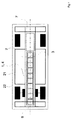
図1は、本発明によるバッテリ収容装置1を搭載した自動車のフレーム21を上から見た概略上面図である。この自動車は、2つの電動機22を有する電気駆動装置を備える。バッテリ収容装置1は、自動車のフレーム21の内部またはアンダーボディの内部に配置される。バッテリ収容空間2の内部に、いくつかのバッテリ3と、変形体9が配置される。バッテリ収容装置1の主延在方向は、自動車の進行方向または長手軸と実質的に平行な向きである。バッテリ収容装置1には退避領域7が配される。この退避領域7は、進行方向で、バッテリ収容装置1の後方に配置される。バッテリ収容装置1は、フレーム21の内部に、バッテリ収容装置の重心の自動車の重心からの水平距離ができるだけ小さくなるように配置される。さらに、バッテリ収容装置1は、自動車の内部にできるだけ低く配置される。これは、自動車の走行安定性に寄与する。
FIG. 1 is a schematic top view of a
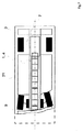
図2は、本発明によるバッテリ収容装置1を備える自動車の側面図である。壁4が、車両前部の領域に、開閉可能な第1の開口5を有する。開閉可能な開口5を開いた後、バッテリ3を出し入れすることもできる。退避領域7は、進行方向で、バッテリ収容装置1の後方に配置される。バッテリ収容装置1は、アンダーボディの内部にできるだけ低く配置される。
FIG. 2 is a side view of an automobile provided with the battery
図3は、自動車のアンダーボディ21と接続された本発明によるバッテリ収容装置1を備える自動車を示す。バッテリ収容装置1の壁4も自動車のアンダーボディ21も、繊維強化ポリマーを含む。バッテリ収容空間2の内部に少なくとも1つのバッテリ3が配置される。バッテリ保持機構は図示されていない。図中に垂直補助線が示されており、この補助線は、バッテリ収容装置1の重心10および自動車の重心23を通って延びている。
FIG. 3 shows an automobile comprising a
図4は、本発明によるバッテリ収容装置1を通る断面図である。バッテリ収容空間2の内部に、少なくとも1つのバッテリ3と、バッテリ保持機構6とが配置される。このバッテリ保持機構6はクランプストリップを有し、クランプストリップは、バッテリ3を保持し、またバッテリ3の移動を案内する働きをする。クランプストリップは、バッテリ保持機構6とねじ留めされる。また少なくとも1つのバッテリ3が、垂直力によってバッテリ保持機構6の底面プレート上に押し付けられる。例えば相応の加速度により摩擦力を超えたときに初めてバッテリ3がずれることがある。
FIG. 4 is a cross-sectional view through the battery
図5は、バッテリ保持機構6がバッテリ収容空間2から一部はみ出していることを示す。バッテリ収容空間2は、大部分が壁4で取り囲まれている。壁4は、開閉可能な第1の開口5を有する。退避領域7は図示されていないが、バッテリ保持機構6は退避領域7内に一部はみ出している。相応にずれたとき、バッテリ3は、少なくとも一部分が通過口8を通って退避領域(図示せず)に入る。
FIG. 5 shows that the
図6は、本発明によるバッテリ収容装置1の通過口8のさらなる実施形態を示す。通過口は、バッテリがずれることによって初めて生じる。それに関して、壁4は、一周する線または一周する帯の形態の目標破断位置を有する。所定の条件で、特に目標破断位置に作用して通過口8を開くのに十分な力が加わると、この目標破断位置が破断される。
FIG. 6 shows a further embodiment of the
図7は、事故後の、本発明によるバッテリ収容装置1を備える自動車を示す。事故により、自動車の車両前部が変形している。ここではフレーム21も変形している。さらに、バッテリ収容装置1の壁4および変形体9も事故により変形していることが図示されている。バッテリ3の1つが退避領域7内に一部ずれ込んでいる。それ以外のバッテリも、事故によりずれている。このずれにより、事故による力およびエネルギーがバッテリ3に及ぼす悪影響が低減される。バッテリ3の筐体を損壊させず、バッテリ3の化学物質の漏出を防ぎ、本発明の根底となる課題を解決する。
FIG. 7 shows an automobile with a
1 バッテリ収容装置
2 バッテリ収容空間
3 バッテリ
4 壁
5 開口
6 バッテリ保持機構
7 退避領域
8 通過口
9 変形体
10 重心
21 フレーム、アンダーボディ
22 電動機
23 重心
1 Battery storage device
2 Battery compartment
3 Battery
4 walls
5 opening
6 Battery retention mechanism
7 Evacuation area
8 Passage
9 variants
10 Center of gravity
21 frames, underbody
22 Electric motor
23 Center of gravity
Claims (14)
前記バッテリ収容空間(2)の少なくとも一部分を取り囲む壁(4)と、
前記壁(4)に配された開閉可能な第1の開口(5)と、
少なくとも1つのバッテリ(3)を保持するように設けられたバッテリ保持機構(6)と、
を備えるバッテリ収容装置(1)において、
前記バッテリ保持機構(6)が、所定の条件で前記少なくとも1つのバッテリ(3)が解放されるように構成されることを特徴とするバッテリ収容装置(1)。 Battery housing space (2);
A wall (4) surrounding at least a portion of the battery housing space (2);
A first opening (5) capable of opening and closing arranged on the wall (4);
A battery holding mechanism (6) provided to hold at least one battery (3);
In a battery housing device (1) comprising:
The battery holding device (1), wherein the battery holding mechanism (6) is configured such that the at least one battery (3) is released under a predetermined condition.
次いで、前記少なくとも1つのバッテリ(3)が、前記バッテリ(3)に作用する力に対応して特に退避空間の方向に移動すること、および
前記少なくとも1つのバッテリ(3)と前記バッテリ収容空間(2)の相対速度が、前記バッテリ(3)が所定の道筋を進んだ後に再び減少すること、
を特徴とする請求項1から13のいずれか一項に記載のバッテリ収容装置(1)を駆動するための方法。 The battery holding mechanism (6) releases at least one battery under a predetermined condition;
Next, the at least one battery (3) moves in the direction of the retracting space in response to the force acting on the battery (3), and the at least one battery (3) and the battery housing space ( The relative speed of 2) decreases again after the battery (3) has traveled a predetermined path;
A method for driving a battery housing device (1) according to any one of the preceding claims.
Applications Claiming Priority (3)
| Application Number | Priority Date | Filing Date | Title |
|---|---|---|---|
| DE200910007422 DE102009007422A1 (en) | 2009-02-04 | 2009-02-04 | Battery Cradle |
| DE102009007422.8 | 2009-02-04 | ||
| PCT/EP2010/000624 WO2010089079A1 (en) | 2009-02-04 | 2010-02-02 | Battery receiving device |
Publications (2)
| Publication Number | Publication Date |
|---|---|
| JP2012517082A true JP2012517082A (en) | 2012-07-26 |
| JP2012517082A5 JP2012517082A5 (en) | 2013-03-21 |
Family
ID=42235852
Family Applications (1)
| Application Number | Title | Priority Date | Filing Date |
|---|---|---|---|
| JP2011548588A Pending JP2012517082A (en) | 2009-02-04 | 2010-02-02 | Battery storage device |
Country Status (7)
| Country | Link |
|---|---|
| US (1) | US20120164496A1 (en) |
| EP (1) | EP2393685B1 (en) |
| JP (1) | JP2012517082A (en) |
| KR (1) | KR20110138347A (en) |
| CN (1) | CN102307742A (en) |
| DE (1) | DE102009007422A1 (en) |
| WO (1) | WO2010089079A1 (en) |
Cited By (2)
| Publication number | Priority date | Publication date | Assignee | Title |
|---|---|---|---|---|
| JP2015123871A (en) * | 2013-12-26 | 2015-07-06 | スズキ株式会社 | Fixing structure of vehicular battery |
| JP2016537766A (en) * | 2013-10-02 | 2016-12-01 | コベストロ、ドイチュラント、アクチエンゲゼルシャフトCovestro Deutschland Ag | Battery module, battery pack and electric vehicle with escape area |
Families Citing this family (26)
| Publication number | Priority date | Publication date | Assignee | Title |
|---|---|---|---|---|
| JP5532877B2 (en) * | 2009-12-03 | 2014-06-25 | マツダ株式会社 | Vehicle battery arrangement structure |
| DE102010039149A1 (en) * | 2010-08-10 | 2012-02-16 | Behr Gmbh & Co. Kg | Wärmeleitmodul and method for producing a heat exchanger |
| DE102011010451A1 (en) | 2011-02-05 | 2012-08-09 | Daimler Ag | Vehicle e.g. electrically propelled vehicle, has heat guide device including heat guide element that is coupled with heat guide plates, where heat guide element forms part of housing of energy storage unit |
| US9070958B2 (en) * | 2011-04-15 | 2015-06-30 | Johnson Controls Technology Llc | Battery system having an external thermal management system |
| DE102011089174A1 (en) | 2011-12-20 | 2013-06-20 | Robert Bosch Gmbh | Battery anode component for a battery cell and method for producing a battery anode component for a battery cell |
| DE102011056892A1 (en) * | 2011-12-22 | 2013-06-27 | Dr. Ing. H.C. F. Porsche Aktiengesellschaft | System for locking electrical storage element i.e. battery, in containment assembly of electrically operated motor car, has electric storage element firmly positioned according to fixation of fastening element in containment assembly |
| ITAR20120019A1 (en) * | 2012-06-22 | 2013-12-23 | Mauro Palombarini | THERMICALLY CONTROLLED MODULAR BATTERY RECHARGE SYSTEM FOR ELECTRIC VEHICLES. |
| DE102013106676A1 (en) | 2013-06-26 | 2014-12-31 | Dr. Ing. H.C. F. Porsche Ag | Motor vehicle, in particular electric vehicle |
| DE102013215116A1 (en) * | 2013-08-01 | 2015-02-05 | Robert Bosch Gmbh | Outer shell for a battery system and battery system with outer shell |
| DE102013226832A1 (en) * | 2013-12-20 | 2015-06-25 | Robert Bosch Gmbh | Grounding arrangement for a vehicle |
| DE102014212575A1 (en) | 2014-06-30 | 2015-12-31 | Robert Bosch Gmbh | Method for guiding a grounding arrangement, guide device for a grounding arrangement and grounding arrangement |
| DE102014215340B4 (en) * | 2014-08-04 | 2017-05-18 | Bayerische Motoren Werke Aktiengesellschaft | Motor vehicle with a tunnel under a passenger compartment |
| DE102016203209B4 (en) * | 2016-02-29 | 2020-11-19 | Ford Global Technologies, Llc | At least partially electrically operated motor vehicle |
| US9722223B1 (en) | 2016-03-02 | 2017-08-01 | Ford Global Technologies, Llc | Battery pack retention assembly and method |
| MX2020000906A (en) * | 2017-07-26 | 2020-07-22 | Autotech Eng Sl | Battery box floor for electric vehicles and corresponding vehicle body. |
| CA3060487A1 (en) * | 2017-12-21 | 2019-06-27 | Electrameccanica Vehicles Corp. | Electric motor vehicle battery system |
| DE102018112602A1 (en) * | 2018-05-25 | 2019-11-28 | Benteler Automobiltechnik Gmbh | Device for receiving at least one accumulator for the operation of a motor vehicle having an electric drive |
| DE102018213542A1 (en) | 2018-08-10 | 2020-02-13 | Audi Ag | Motor vehicle with an electric drive, HV alternating energy storage and system |
| DE102019110536A1 (en) * | 2019-04-24 | 2020-10-29 | Bayerische Motoren Werke Aktiengesellschaft | Battery cell module and motor vehicle |
| CN110034259B (en) * | 2019-04-29 | 2022-08-02 | 广州中国科学院工业技术研究院 | Method for preventing sympathetic explosion of battery pack |
| DE102019004891A1 (en) * | 2019-07-15 | 2021-01-21 | Marquardt Gmbh | Battery system |
| US20220278415A1 (en) * | 2019-09-09 | 2022-09-01 | Kirchhoff Automotive Deutschland Gmbh | Battery Housing Comprising A Spacer |
| DE102019128476A1 (en) * | 2019-10-22 | 2021-04-22 | Dr. Ing. H.C. F. Porsche Aktiengesellschaft | Traction battery system for a motor vehicle |
| US11472278B2 (en) * | 2020-09-22 | 2022-10-18 | Ford Global Technologies, Llc | Traction battery protection assembly and method |
| JP7468434B2 (en) | 2021-03-30 | 2024-04-16 | マツダ株式会社 | Body structure |
| AT526382A1 (en) * | 2022-08-09 | 2024-02-15 | Avl List Gmbh | Commercial vehicle with fuel cell cooling system |
Citations (9)
| Publication number | Priority date | Publication date | Assignee | Title |
|---|---|---|---|---|
| JPH0554105U (en) * | 1991-12-25 | 1993-07-20 | 日野自動車工業株式会社 | Battery fixing device for vehicle |
| JPH0648185A (en) * | 1992-07-29 | 1994-02-22 | Kanto Auto Works Ltd | Battery fitting structure of electric automobile |
| JPH0655940A (en) * | 1992-06-11 | 1994-03-01 | Peugeot Sa <Psa> | Electric car |
| JPH07117489A (en) * | 1993-10-20 | 1995-05-09 | Mazda Motor Corp | Battery attaching structure of electric automobile |
| JPH07323735A (en) * | 1994-05-31 | 1995-12-12 | Nissan Motor Co Ltd | Battery mounting structure of electric vehicle |
| JP2004237803A (en) * | 2003-02-04 | 2004-08-26 | Toyota Motor Corp | Battery installation structure for vehicle |
| JP2006182099A (en) * | 2004-12-27 | 2006-07-13 | Nissan Motor Co Ltd | Battery mounting structure |
| JP2008162500A (en) * | 2006-12-28 | 2008-07-17 | Mitsubishi Motors Corp | Battery mounting structure of electric automobile |
| JP2008222041A (en) * | 2007-03-13 | 2008-09-25 | Mazda Motor Corp | Battery cooling device for automobile |
Family Cites Families (5)
| Publication number | Priority date | Publication date | Assignee | Title |
|---|---|---|---|---|
| IT1060639B (en) * | 1975-05-23 | 1982-08-20 | Bayerische Motoren Werke Ag | Battery mounting for electric vehicle - having underfloor mounting brackets with shear fasteners for collision safety |
| US4216839A (en) * | 1978-07-20 | 1980-08-12 | Unique Mobility Inc. | Electrically powered motor vehicle |
| DE4032605A1 (en) * | 1990-09-19 | 1992-03-26 | Eckard Design Gmbh | Electric powered road vehicle - has hollow section running along vehicle to accommodate batteries as central torsion tube |
| DE4235394C1 (en) * | 1992-10-21 | 1993-10-14 | Daimler Benz Ag | Drive battery for electric automobile - has individual cells loosely stacked in battery housing with rupture points separating to release cells in response to impact force of accident |
| US6085854A (en) * | 1994-12-13 | 2000-07-11 | Nissan Motor Co., Ltd. | Battery frame structure for electric motorcar |
-
2009
- 2009-02-04 DE DE200910007422 patent/DE102009007422A1/en not_active Withdrawn
-
2010
- 2010-02-02 JP JP2011548588A patent/JP2012517082A/en active Pending
- 2010-02-02 CN CN2010800066846A patent/CN102307742A/en active Pending
- 2010-02-02 US US13/147,657 patent/US20120164496A1/en not_active Abandoned
- 2010-02-02 EP EP10702833.4A patent/EP2393685B1/en not_active Not-in-force
- 2010-02-02 KR KR1020117020745A patent/KR20110138347A/en not_active Application Discontinuation
- 2010-02-02 WO PCT/EP2010/000624 patent/WO2010089079A1/en active Application Filing
Patent Citations (9)
| Publication number | Priority date | Publication date | Assignee | Title |
|---|---|---|---|---|
| JPH0554105U (en) * | 1991-12-25 | 1993-07-20 | 日野自動車工業株式会社 | Battery fixing device for vehicle |
| JPH0655940A (en) * | 1992-06-11 | 1994-03-01 | Peugeot Sa <Psa> | Electric car |
| JPH0648185A (en) * | 1992-07-29 | 1994-02-22 | Kanto Auto Works Ltd | Battery fitting structure of electric automobile |
| JPH07117489A (en) * | 1993-10-20 | 1995-05-09 | Mazda Motor Corp | Battery attaching structure of electric automobile |
| JPH07323735A (en) * | 1994-05-31 | 1995-12-12 | Nissan Motor Co Ltd | Battery mounting structure of electric vehicle |
| JP2004237803A (en) * | 2003-02-04 | 2004-08-26 | Toyota Motor Corp | Battery installation structure for vehicle |
| JP2006182099A (en) * | 2004-12-27 | 2006-07-13 | Nissan Motor Co Ltd | Battery mounting structure |
| JP2008162500A (en) * | 2006-12-28 | 2008-07-17 | Mitsubishi Motors Corp | Battery mounting structure of electric automobile |
| JP2008222041A (en) * | 2007-03-13 | 2008-09-25 | Mazda Motor Corp | Battery cooling device for automobile |
Cited By (2)
| Publication number | Priority date | Publication date | Assignee | Title |
|---|---|---|---|---|
| JP2016537766A (en) * | 2013-10-02 | 2016-12-01 | コベストロ、ドイチュラント、アクチエンゲゼルシャフトCovestro Deutschland Ag | Battery module, battery pack and electric vehicle with escape area |
| JP2015123871A (en) * | 2013-12-26 | 2015-07-06 | スズキ株式会社 | Fixing structure of vehicular battery |
Also Published As
| Publication number | Publication date |
|---|---|
| EP2393685B1 (en) | 2013-05-08 |
| DE102009007422A1 (en) | 2010-08-05 |
| US20120164496A1 (en) | 2012-06-28 |
| WO2010089079A1 (en) | 2010-08-12 |
| CN102307742A (en) | 2012-01-04 |
| KR20110138347A (en) | 2011-12-27 |
| EP2393685A1 (en) | 2011-12-14 |
Similar Documents
| Publication | Publication Date | Title |
|---|---|---|
| JP2012517082A (en) | Battery storage device | |
| JP6266261B2 (en) | Automotive battery | |
| JP5141026B2 (en) | In-vehicle structure of power storage pack | |
| US8037960B2 (en) | Structure for mounting electricity storage pack on vehicle | |
| KR102312415B1 (en) | Battery module, battery pack comprising the battery module and vehicle comprising the battery pack | |
| JP2012517082A5 (en) | ||
| US20140017546A1 (en) | Battery pack of vehicle | |
| JP2017065474A (en) | On-vehicle battery | |
| CN101263030B (en) | Structure for installing electric component | |
| JP2008123846A (en) | Storage battery unit | |
| US20080160394A1 (en) | Structure for mounting batteries onto electric vehicles | |
| JP5216316B2 (en) | Integrated package vertical mounting frame structure | |
| US11364782B2 (en) | Motor vehicle having a plurality of battery modules | |
| WO2013054373A1 (en) | Structure for mounting electric power storage device | |
| KR20220031045A (en) | Hybrid energy absorption for vehicle battery pack frame | |
| JP4978316B2 (en) | Automotive electronic unit | |
| JP2016132314A (en) | Onboard battery | |
| EP2851230A1 (en) | Vehicle | |
| JP2017137002A (en) | Battery mounting structure of electric vehicle | |
| JP2010064687A (en) | Carpet for vehicle | |
| JP2017152187A (en) | Battery for on-vehicle | |
| US9837690B2 (en) | Battery cooling fan mounting | |
| KR101324012B1 (en) | Electric vehicles for agriculture | |
| JP5998825B2 (en) | High voltage harness protection structure | |
| JP2016177943A (en) | Gas discharge structure of battery |
Legal Events
| Date | Code | Title | Description |
|---|---|---|---|
| A521 | Request for written amendment filed |
Free format text: JAPANESE INTERMEDIATE CODE: A523 Effective date: 20130130 |
|
| A621 | Written request for application examination |
Free format text: JAPANESE INTERMEDIATE CODE: A621 Effective date: 20130130 |
|
| A977 | Report on retrieval |
Free format text: JAPANESE INTERMEDIATE CODE: A971007 Effective date: 20140131 |
|
| A131 | Notification of reasons for refusal |
Free format text: JAPANESE INTERMEDIATE CODE: A131 Effective date: 20140210 |
|
| A601 | Written request for extension of time |
Free format text: JAPANESE INTERMEDIATE CODE: A601 Effective date: 20140430 |
|
| A602 | Written permission of extension of time |
Free format text: JAPANESE INTERMEDIATE CODE: A602 Effective date: 20140509 |
|
| A02 | Decision of refusal |
Free format text: JAPANESE INTERMEDIATE CODE: A02 Effective date: 20141014 |