JP2012254205A - Swing analyzing device, swing analyzing program, and recording medium - Google Patents
Swing analyzing device, swing analyzing program, and recording medium Download PDFInfo
- Publication number
- JP2012254205A JP2012254205A JP2011129134A JP2011129134A JP2012254205A JP 2012254205 A JP2012254205 A JP 2012254205A JP 2011129134 A JP2011129134 A JP 2011129134A JP 2011129134 A JP2011129134 A JP 2011129134A JP 2012254205 A JP2012254205 A JP 2012254205A
- Authority
- JP
- Japan
- Prior art keywords
- swing
- data
- timing
- motion
- impact
- Prior art date
- Legal status (The legal status is an assumption and is not a legal conclusion. Google has not performed a legal analysis and makes no representation as to the accuracy of the status listed.)
- Granted
Links
- 230000033001 locomotion Effects 0.000 claims abstract description 165
- 238000001514 detection method Methods 0.000 claims abstract description 148
- 239000000284 extract Substances 0.000 claims abstract description 6
- 238000012545 processing Methods 0.000 claims description 81
- 230000033764 rhythmic process Effects 0.000 description 89
- 238000000034 method Methods 0.000 description 67
- 230000008569 process Effects 0.000 description 61
- 238000012986 modification Methods 0.000 description 17
- 230000004048 modification Effects 0.000 description 17
- 230000006870 function Effects 0.000 description 13
- 238000013459 approach Methods 0.000 description 9
- 230000001133 acceleration Effects 0.000 description 5
- 230000009471 action Effects 0.000 description 4
- 238000004891 communication Methods 0.000 description 4
- 230000007423 decrease Effects 0.000 description 4
- 230000004069 differentiation Effects 0.000 description 4
- 230000008859 change Effects 0.000 description 3
- 238000006243 chemical reaction Methods 0.000 description 2
- 238000010586 diagram Methods 0.000 description 2
- 230000000694 effects Effects 0.000 description 2
- 238000005259 measurement Methods 0.000 description 2
- 238000010606 normalization Methods 0.000 description 2
- 241000288673 Chiroptera Species 0.000 description 1
- 125000002066 L-histidyl group Chemical group [H]N1C([H])=NC(C([H])([H])[C@](C(=O)[*])([H])N([H])[H])=C1[H] 0.000 description 1
- 238000009825 accumulation Methods 0.000 description 1
- 239000000470 constituent Substances 0.000 description 1
- 238000002474 experimental method Methods 0.000 description 1
- 230000003287 optical effect Effects 0.000 description 1
- 238000000926 separation method Methods 0.000 description 1
Images


Classifications
-
- A—HUMAN NECESSITIES
- A63—SPORTS; GAMES; AMUSEMENTS
- A63B—APPARATUS FOR PHYSICAL TRAINING, GYMNASTICS, SWIMMING, CLIMBING, OR FENCING; BALL GAMES; TRAINING EQUIPMENT
- A63B24/00—Electric or electronic controls for exercising apparatus of preceding groups; Controlling or monitoring of exercises, sportive games, training or athletic performances
- A63B24/0003—Analysing the course of a movement or motion sequences during an exercise or trainings sequence, e.g. swing for golf or tennis
-
- G—PHYSICS
- G06—COMPUTING; CALCULATING OR COUNTING
- G06V—IMAGE OR VIDEO RECOGNITION OR UNDERSTANDING
- G06V40/00—Recognition of biometric, human-related or animal-related patterns in image or video data
- G06V40/20—Movements or behaviour, e.g. gesture recognition
- G06V40/23—Recognition of whole body movements, e.g. for sport training
-
- G—PHYSICS
- G06—COMPUTING; CALCULATING OR COUNTING
- G06F—ELECTRIC DIGITAL DATA PROCESSING
- G06F18/00—Pattern recognition
-
- A—HUMAN NECESSITIES
- A63—SPORTS; GAMES; AMUSEMENTS
- A63B—APPARATUS FOR PHYSICAL TRAINING, GYMNASTICS, SWIMMING, CLIMBING, OR FENCING; BALL GAMES; TRAINING EQUIPMENT
- A63B24/00—Electric or electronic controls for exercising apparatus of preceding groups; Controlling or monitoring of exercises, sportive games, training or athletic performances
- A63B24/0003—Analysing the course of a movement or motion sequences during an exercise or trainings sequence, e.g. swing for golf or tennis
- A63B24/0006—Computerised comparison for qualitative assessment of motion sequences or the course of a movement
-
- A—HUMAN NECESSITIES
- A63—SPORTS; GAMES; AMUSEMENTS
- A63B—APPARATUS FOR PHYSICAL TRAINING, GYMNASTICS, SWIMMING, CLIMBING, OR FENCING; BALL GAMES; TRAINING EQUIPMENT
- A63B69/00—Training appliances or apparatus for special sports
- A63B69/36—Training appliances or apparatus for special sports for golf
- A63B69/3623—Training appliances or apparatus for special sports for golf for driving
- A63B69/3632—Clubs or attachments on clubs, e.g. for measuring, aligning
-
- G—PHYSICS
- G06—COMPUTING; CALCULATING OR COUNTING
- G06F—ELECTRIC DIGITAL DATA PROCESSING
- G06F2218/00—Aspects of pattern recognition specially adapted for signal processing
- G06F2218/12—Classification; Matching
- G06F2218/14—Classification; Matching by matching peak patterns
-
- G—PHYSICS
- G09—EDUCATION; CRYPTOGRAPHY; DISPLAY; ADVERTISING; SEALS
- G09B—EDUCATIONAL OR DEMONSTRATION APPLIANCES; APPLIANCES FOR TEACHING, OR COMMUNICATING WITH, THE BLIND, DEAF OR MUTE; MODELS; PLANETARIA; GLOBES; MAPS; DIAGRAMS
- G09B19/00—Teaching not covered by other main groups of this subclass
- G09B19/003—Repetitive work cycles; Sequence of movements
- G09B19/0038—Sports
Landscapes
- Engineering & Computer Science (AREA)
- General Health & Medical Sciences (AREA)
- Health & Medical Sciences (AREA)
- Theoretical Computer Science (AREA)
- Physical Education & Sports Medicine (AREA)
- Physics & Mathematics (AREA)
- Computer Vision & Pattern Recognition (AREA)
- General Physics & Mathematics (AREA)
- General Engineering & Computer Science (AREA)
- Psychiatry (AREA)
- Life Sciences & Earth Sciences (AREA)
- Evolutionary Biology (AREA)
- Data Mining & Analysis (AREA)
- Bioinformatics & Computational Biology (AREA)
- Bioinformatics & Cheminformatics (AREA)
- Evolutionary Computation (AREA)
- Social Psychology (AREA)
- Human Computer Interaction (AREA)
- Multimedia (AREA)
- Artificial Intelligence (AREA)
- Golf Clubs (AREA)
- User Interface Of Digital Computer (AREA)
- Measurement Of The Respiration, Hearing Ability, Form, And Blood Characteristics Of Living Organisms (AREA)
Abstract
Description
本発明は、スイング分析装置、スイング分析プログラム、およびスイング分析プログラムを記録した記録媒体に関する。 The present invention relates to a swing analysis device, a swing analysis program, and a recording medium on which the swing analysis program is recorded.
ゴルフ、テニス、野球などのスポーツでは、スイングのリズムを改善することで競技力を向上させることができると考えられている。特に、ゴルフでは静止したボールを打つため、スイングの各フェーズ(バックスイング、トップ、ダウンスイング、インパクト、フォロースルー)のリズム(時間配分)が安定しているほど良いスイングができているとの見方があり、練習用具などでは各フェーズの時間のばらつきなどを計測し、分析のための情報を提供しているものもある。また、特許文献1では、練習者の身体の加速度を検知し、この加速度情報を解析することでバックスイング期間、ダウンスイング(フォワードスイング)期間、フォロースルー期間などを算出する手法が提案されている。さらに、特許文献2では、ユーザーの体幹軸の動きを検出できる部位に角速度センサー等のモーションセンサーを取り付け、ゴルフスイングによって生じる角速度を測定し、この角速度情報を解析することでバックスイング、ダウンスイング、フォロースルーなどの時間を算出する手法が提案されている。
In sports such as golf, tennis, and baseball, it is considered that the competitiveness can be improved by improving the swing rhythm. In particular, because golf hits a stationary ball, the more stable the rhythm (time allocation) of each phase of the swing (back swing, top, down swing, impact, follow-through) is, There are some exercise tools that provide information for analysis by measuring the time variation of each phase. Patent Document 1 proposes a method for calculating a backswing period, a downswing (forward swing) period, a follow-through period, and the like by detecting the acceleration of the practitioner's body and analyzing the acceleration information. . Furthermore, in
しかしながら、スイングの計測では、計測の開始と終了のタイミングをユーザーが指定する必要がある場合が多く、スイング動作が制限されていつもどおりの自然な動きの中でのスイングの計測ができない場合が多い。また、一般的にモーションセンサーのセンシングデータの中からスイング動作に対応するスイングデータを抽出するためには、波形のパターンマッチングにより適合するパターンを見つける処理を行っており、計算負荷が大きいという問題がある。 However, in swing measurement, it is often necessary for the user to specify the start and end timing of the measurement, and the swing movement is limited, and it is often impossible to measure the swing in natural movement as usual. . In general, in order to extract the swing data corresponding to the swing motion from the sensing data of the motion sensor, a process for finding a suitable pattern by waveform pattern matching is performed, and there is a problem that the calculation load is heavy. is there.
本発明は、以上のような問題点に鑑みてなされたものであり、本発明のいくつかの態様によれば、ユーザーがスイング動作の開始や終了のタイミングを指示する必要がなく、比較的小さい計算負荷でスイングデータの抽出を行うことが可能なスイング分析装置、スイング分析プログラム、およびスイング分析プログラムを記録した記録媒体を提供することができる。 The present invention has been made in view of the above problems, and according to some aspects of the present invention, it is not necessary for the user to instruct the timing for starting and ending the swing motion, and is relatively small. It is possible to provide a swing analysis apparatus capable of extracting swing data with a calculation load, a swing analysis program, and a recording medium on which the swing analysis program is recorded.
(1)本発明は、スイングにより発生する物理量を検出するモーションセンサーと、前記モーションセンサーの検出データを取得するデータ取得部と、取得した前記検出データを用いて前記スイングの動作の検出を行い、前記スイングの動作が検出されたデータをスイング候補データとして抽出する動作検出部と、前記スイングに関連付けられる判定条件に基づき、前記スイング候補データから真のスイングデータを選択するスイングデータ判定部と、を含む、スイング分析装置である。 (1) The present invention detects a motion of the swing using a motion sensor that detects a physical quantity generated by a swing, a data acquisition unit that acquires detection data of the motion sensor, and the acquired detection data, A motion detection unit that extracts data from which the swing motion is detected as swing candidate data; and a swing data determination unit that selects true swing data from the swing candidate data based on a determination condition associated with the swing. Including a swing analyzer.
本発明のスイング分析装置によれば、モーションセンサーから取得した検出データからスイング候補データを抽出し、スイング候補データが真のスイングデータであるか否かを判定するので、ユーザーがスイング動作の開始や終了のタイミングを指示する必要がない。 According to the swing analysis device of the present invention, the swing candidate data is extracted from the detection data acquired from the motion sensor, and it is determined whether or not the swing candidate data is true swing data. There is no need to indicate the end timing.
また、本発明のスイング分析装置によれば、検出したリズムの妥当性を評価することによりスイング候補データが真のスイングデータであるか否かを判定するので、波形のパターンマッチングを行う場合と比較して、より小さい計算負荷でスイングデータを抽出することができる。 Further, according to the swing analysis device of the present invention, it is determined whether or not the swing candidate data is true swing data by evaluating the validity of the detected rhythm, so that it is compared with the case of performing waveform pattern matching. Thus, swing data can be extracted with a smaller calculation load.
(2)このスイング分析装置において、前記動作検出部は、取得した前記検出データを用いて前記スイングのインパクトのタイミングを検出するインパクト検出部を含み、前記インパクトのタイミングを基準に前記スイング候補データの前記スイングの動作を検出するようにしてもよい。 (2) In this swing analyzer, the motion detection unit includes an impact detection unit that detects the timing of the impact of the swing using the acquired detection data, and the swing candidate data of the swing candidate data is based on the timing of the impact. The swing motion may be detected.
インパクトの瞬間は角速度の値が急激に変化するので、一連のスイング動作の中でインパクトのタイミングが最も捉えやすい。そこで、インパクトのタイミングを最初に検出し、インパクトのタイミングを基準とすることで、より確実にスイングの各動作の検出を行うことができる。 At the moment of impact, the value of angular velocity changes abruptly, so the impact timing is the easiest to capture in a series of swing movements. Therefore, by detecting the impact timing first and using the impact timing as a reference, it is possible to more reliably detect each swing operation.
(3)このスイング分析装置において、前記スイングの動作は、バックスイング、トップ、およびダウンスイングの少なくとも1つの動作を含むようにしてもよい。 (3) In this swing analyzer, the swing operation may include at least one of a back swing, a top swing, and a down swing.
(4)このスイング分析装置において、前記スイングデータ判定部が、1つの前記スイング候補データにおいて、前記インパクトのタイミングが1つであることを前記判定条件の1つとしているようにしてもよい。 (4) In this swing analysis apparatus, the swing data determination unit may make one of the determination conditions that the impact timing is one in one swing candidate data.
通常のスイング動作では、スイングの開始から終了までにインパクトが1つであると考えられる。従って、スイング候補データの期間にインパクトのタイミングが1つでなければ当該スイング候補データは真のスイングデータではないと判定することができる。 In a normal swing operation, it is considered that there is one impact from the start to the end of the swing. Therefore, if there is no single impact timing in the swing candidate data period, it can be determined that the swing candidate data is not true swing data.
(5)このスイング分析装置において、前記スイングデータ判定部が、1つの前記スイング候補データにおいて、前記ダウンスイングの時間が前記バックスイングの時間よりも短いことを前記判定条件の1つとしているようにしてもよい。 (5) In this swing analyzer, the swing data determination unit may make one of the determination conditions that the downswing time is shorter than the backswing time in one swing candidate data. May be.
通常のスイング動作では、ダウンスイングの時間がバックスイングの時間よりも短いと考えられる。従って、スイング候補データにおけるダウンスイングの時間がバックスイングの時間よりも長ければ当該スイング候補データは真のスイングデータではないと判定することができる。 In a normal swing operation, it is considered that the downswing time is shorter than the backswing time. Therefore, if the downswing time in the swing candidate data is longer than the backswing time, it can be determined that the swing candidate data is not true swing data.
(6)このスイング分析装置において、前記スイングデータ判定部が、1つの前記スイング候補データにおいて、前記トップの時間を前記スイング候補データの前記スイングの開始から前記スイングの終了までの時間で割った値が第1閾値よりも小さいことを前記判定条件の1つとしているようにしてもよい。 (6) In this swing analyzer, the swing data determination unit is a value obtained by dividing the time of the top by the time from the start of the swing to the end of the swing of the swing candidate data in one swing candidate data. One of the determination conditions may be that is smaller than the first threshold.
通常のスイング動作では、トップ区間の時間と全時間との比が所定範囲であると考えられる。従って、トップ区間の時間と全時間との比が所定範囲でなければ当該スイング候補データは真のスイングデータではないと判定することができる。 In a normal swing operation, the ratio between the time of the top section and the total time is considered to be within a predetermined range. Therefore, if the ratio between the time of the top section and the total time is not within a predetermined range, it can be determined that the swing candidate data is not true swing data.
(7)このスイング分析装置において、前記第1閾値は15%であるようにしてもよい。 (7) In this swing analyzer, the first threshold value may be 15%.
(8)このスイング分析装置において、前記モーションセンサーは、前記スイングにより複数軸の回りに発生する角速度を検出する角速度センサーであり、前記動作検出部は、取得した前記検出データを用いて、前記複数軸の各々の軸に発生する前記角速度の大きさの和を計算する角速度計算部を含むようにしてもよい。 (8) In this swing analysis apparatus, the motion sensor is an angular velocity sensor that detects angular velocities generated around a plurality of axes by the swing, and the motion detection unit uses the acquired detection data to detect the plurality of motion sensors. You may make it include the angular velocity calculation part which calculates the sum of the magnitude | size of the said angular velocity generate | occur | produced in each axis | shaft of an axis | shaft.
このように、角速度センサーを用いることで、加速度センサーを用いた場合と比較してスイング動作をより正確に検出するとともに、動きの小さいスイングも検出可能である。 As described above, by using the angular velocity sensor, it is possible to detect the swing motion more accurately than in the case of using the acceleration sensor, and it is also possible to detect a swing with a small movement.
さらに、角速度センサーにより複数軸の角速度を検出し、各々の軸回りの角速度の大きさの和(ノルム)に基づいてスイングの各動作を検出するので、スイング動作に連動して動く場所に任意の向きに角速度センサーを取り付けることができ、取り扱いが容易である。 In addition, the angular velocity sensor detects the angular velocities of multiple axes and detects each swing motion based on the sum (norm) of the angular velocities around each axis. An angular velocity sensor can be attached in the direction, and handling is easy.
(9)このスイング分析装置において、前記動作検出部は、前記角速度の大きさの和を用いて、前記スイングにおけるインパクトのタイミングを検出するようにしてもよい。 (9) In this swing analyzer, the motion detection unit may detect the timing of impact in the swing using the sum of the magnitudes of the angular velocities.
インパクトの瞬間は角速度の大きさの和(ノルム)の値が急激に変化するので、一連のスイング動作の中でインパクトのタイミングが最も捉えやすい。そこで、インパクトのタイミングを最初に検出することで、より確実にスイングの各動作の検出を行うことができる。 At the moment of impact, the value of the sum (norm) of the angular velocities changes abruptly, so the impact timing is the easiest to grasp in a series of swing movements. Therefore, by detecting the impact timing first, each motion of the swing can be detected more reliably.
(10)このスイング分析装置において、前記動作検出部は、前記角速度の大きさの和を時間で微分する微分計算部をさらに含むようにしてもよい。 (10) In this swing analyzer, the motion detection unit may further include a differential calculation unit that differentiates the sum of the magnitudes of the angular velocities with respect to time.
(11)このスイング分析装置において、前記動作検出部は、前記微分の値で正のピークと負のピークとが連続する部分を検出し、前記正のピークおよび前記負のピークのうち先のピークのタイミングをインパクトのタイミングとして検出するようにしてもよい。 (11) In this swing analyzer, the motion detection unit detects a portion where a positive peak and a negative peak are continuous in the differential value, and the previous peak of the positive peak and the negative peak is detected. The timing may be detected as the impact timing.
通常のスイング動作では、インパクトの際にその衝撃により角速度が急激に変化する。したがって、一連のスイング動作の中で角速度の大きさの和(ノルム)の微分値が極大又は極小となるタイミング(すなわち、角速度の大きさの和の微分値が正のピーク又は負のピークになるタイミング)をインパクトのタイミングとして捉えることができる。なお、スイングに用いられる器具がインパクトにより振動するため、角速度の大きさの和(ノルム)の微分値が極大となるタイミングと極小となるタイミングが対になって生じると考えられるが、そのうちの先のタイミングがインパクトの瞬間と考えられる。 In a normal swing operation, the angular velocity changes suddenly due to the impact at the time of impact. Therefore, the timing at which the differential value of the sum (norm) of the magnitudes of angular velocities becomes maximum or minimum in a series of swing operations (that is, the differential value of the sum of magnitudes of angular velocities becomes a positive peak or a negative peak. Timing) can be taken as the timing of impact. In addition, since the instrument used for the swing vibrates due to impact, it is considered that the timing at which the differential value of the sum of the angular velocities (norm) is maximized and the timing at which it is minimized are paired. This timing is considered the moment of impact.
(12)このスイング分析装置において、前記動作検出部は、前記インパクトより前で、前記角速度の大きさの和が極小となるタイミングを前記スイングのトップのタイミングとして検出するようにしてもよい。 (12) In this swing analysis apparatus, the motion detection unit may detect a timing at which the sum of the magnitudes of the angular velocities is minimized before the impact as the top timing of the swing.
通常のスイング動作では、スイング開始後、トップで一旦動作が止まり、その後、徐々にスイング速度が大きくなってインパクトに至ると考えられる。従って、インパクトのタイミングより前で角速度の大きさの和(ノルム)が極小となるタイミングをスイングのトップのタイミングとして捉えることができる。 In a normal swing motion, it is considered that after the start of the swing, the motion is temporarily stopped at the top, and then the swing speed is gradually increased to cause an impact. Therefore, the timing at which the sum (norm) of the angular velocities is minimized before the impact timing can be regarded as the top timing of the swing.
(13)このスイング分析装置において、前記動作検出部は、前記トップより前で、前記角速度の大きさの和が第2閾値以下となるタイミングを前記スイングの開始のタイミングとして検出するようにしてもよい。 (13) In this swing analysis device, the motion detection unit may detect, as the start timing of the swing, the timing before the top and the sum of the magnitudes of the angular velocities is equal to or less than a second threshold value. Good.
通常のスイング動作では、静止した状態からスイング動作を開始し、トップまでにスイング動作が止まることは考えにくい。従って、トップより前で、角速度の大きさの和(ノルム)が第2閾値以下となる最後のタイミングをスイングの開始のタイミングとして捉えることができる。 In a normal swing operation, it is unlikely that the swing operation starts from a stationary state and stops until the top. Therefore, the last timing when the sum (norm) of the magnitudes of the angular velocities is less than or equal to the second threshold value before the top can be regarded as the swing start timing.
(14)このスイング分析装置において、前記動作検出部は、前記インパクトより後で、前記角速度の大きさの和が極小となるタイミングを前記スイングのフィニッシュのタイミングとして検出するようにしてもよい。 (14) In this swing analysis apparatus, the motion detection unit may detect a timing at which the sum of the magnitudes of the angular velocities becomes a minimum after the impact as a finish timing of the swing.
通常のスイング動作では、インパクトの後、徐々にスイング速度が小さくなって止まると考えられる。従って、インパクトより後で、角速度の大きさの和(ノルム)が極小となるタイミングをフィニッシュのタイミングとして捉えることができる。 In a normal swing operation, it is considered that the swing speed gradually decreases after impact and stops. Therefore, after the impact, the timing at which the sum (norm) of the magnitudes of the angular velocities becomes minimum can be regarded as the finish timing.
(15)このスイング分析装置において、前記動作検出部は、前記インパクトより後で、前記角速度の大きさの和が第3閾値以下となる最初のタイミングを前記スイングのフィニッシュのタイミングとして検出するようにしてもよい。 (15) In this swing analyzer, the motion detection unit detects, as the finish timing of the swing, the first timing after the impact when the sum of the magnitudes of the angular velocities is equal to or less than a third threshold value. May be.
通常のスイング動作では、インパクトの後、徐々にスイング速度が小さくなって止まると考えられる。従って、インパクトより後で、角速度の大きさの和(ノルム)が第3閾値以下となる最初のタイミングをフィニッシュのタイミングとして捉えることができる。 In a normal swing operation, it is considered that the swing speed gradually decreases after impact and stops. Therefore, the first timing at which the sum (norm) of the magnitudes of the angular velocities becomes less than or equal to the third threshold value after the impact can be regarded as the finish timing.
(16)このスイング分析装置において、前記動作検出部は、前記スイングの開始のタイミングから前記トップのタイミングまでの間をバックスイングの区間として特定し、前記トップのタイミングから前記インパクトのタイミングまでの間をダウンスイングの区間として特定するようにしてもよい。 (16) In this swing analyzer, the motion detection unit identifies a period from the start timing of the swing to the top timing as a backswing section, and from the top timing to the impact timing. May be specified as a downswing section.
(17)このスイング分析装置において、前記角速度センサーは、ユーザーの手、グローブ、およびスイング器具の少なくとも1つに取り付け可能であるようにしてもよい。 (17) In this swing analyzer, the angular velocity sensor may be attachable to at least one of a user's hand, a glove, and a swing device.
角速度センサーをユーザーの手またはグローブに取り付け可能とすることにより、センサーの取り付けに時間がかからず、容易にスイング解析を行うことができる。また、角速度センサーをスイング器具に取り付け可能とすることにより、ユーザーの手またはグローブにセンサーを取り付けるよりも精密に角速度を検出することができる。 By making the angular velocity sensor attachable to the user's hand or glove, it is possible to easily perform swing analysis without taking time to attach the sensor. In addition, by allowing the angular velocity sensor to be attached to the swing device, the angular velocity can be detected more precisely than attaching the sensor to the user's hand or glove.
(18)このスイング分析装置は、前記動作検出部が検出した前記スイングの動作に基づいて、前記スイングの動作の時間を算出し、算出結果を画面に表示する表示処理部をさらに含むようにしてもよい。 (18) The swing analysis apparatus may further include a display processing unit that calculates a time of the swing operation based on the swing operation detected by the operation detection unit and displays the calculation result on a screen. .
このように、スイング動作の各動作の少なくとも1つの時間を表示することで、ユーザーはスイングの詳細な動作を把握することができる。 In this way, by displaying at least one time of each operation of the swing operation, the user can grasp the detailed operation of the swing.
(19)このスイング分析装置において、前記スイングは、ゴルフのスイングであるようにしてもよい。すなわち、ゴルフスイング分析装置であってもよい。 (19) In this swing analyzer, the swing may be a golf swing. That is, a golf swing analyzer may be used.
(20)本発明は、モーションセンサーからスイングにより発生する物理量の検出データを取得するデータ取得部と、取得した前記検出データを用いて前記スイングの動作の検出を行い、前記スイングの動作が検出されたデータをスイング候補データとして抽出する動作検出部と、前記スイングに関連付けられる判定条件に基づき、当該スイング候補データから真のスイングデータを選択するスイングデータ判定部としてコンピューターを機能させる、スイング分析プログラムである。 (20) In the present invention, a data acquisition unit that acquires detection data of a physical quantity generated by a swing from a motion sensor, and the swing operation is detected using the acquired detection data, and the swing operation is detected. A swing analysis program that causes a computer to function as a motion detection unit that extracts data as swing candidate data and a swing data determination unit that selects true swing data from the swing candidate data based on the determination condition associated with the swing is there.
(21)本発明は、上記のスイング分析プログラムを記録した記録媒体である。 (21) The present invention is a recording medium on which the swing analysis program is recorded.
以下、本発明の好適な実施形態について図面を用いて詳細に説明する。なお、以下に説明する実施の形態は、特許請求の範囲に記載された本発明の内容を不当に限定するものではない。また以下で説明される構成の全てが本発明の必須構成要件であるとは限らない。 DESCRIPTION OF EMBODIMENTS Hereinafter, preferred embodiments of the present invention will be described in detail with reference to the drawings. The embodiments described below do not unduly limit the contents of the present invention described in the claims. Also, not all of the configurations described below are essential constituent requirements of the present invention.
以下では、ゴルフスイングの分析を行うスイング分析装置を例に挙げて説明するが、本発明のスイング分析装置は、テニスラケットや野球のバットなどスイングに用いられる様々な器具のスイング分析に適用することができる。 In the following, a swing analysis device that analyzes golf swings will be described as an example, but the swing analysis device of the present invention is applied to swing analysis of various equipment used for swings such as tennis rackets and baseball bats. Can do.
1.スイング分析装置の構成
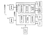
図1は、本実施形態のスイング分析装置の構成を示す図である。本実施形態のスイング分析装置1は、モーションセンサー10、処理部20、操作部30、表示部40、ROM50、RAM60、不揮発性メモリー70、記録媒体80を含んで構成されている。
1. Configuration of Swing Analyzer FIG. 1 is a diagram showing a configuration of a swing analyzer according to this embodiment. The swing analysis apparatus 1 according to the present embodiment includes a
モーションセンサー10は、スイングにより発生する物理量を検出し、検出データを出力する。なお、モーションセンサー10は、1つの素子で複数軸の物理量を検出可能な多軸センサーであっても良いし、1つの素子で1軸の物理量を検出可能な1軸センサーを複数個実装したセンサーであっても良い。モーションセンサー10としては、角速度センサーや加速度センサーなどを適用することができる。特に、本実施形態のモーションセンサー10は角速度センサーであり、複数軸の回りの角速度を検出し、各軸回りの角速度の検出データを出力する。
The
操作部30は、ユーザーからの操作データを取得し、処理部20に送る処理を行う。操作部30は、例えば、タッチパネル型ディスプレイ、ボタン、キー、マイクなどである。
The
表示部40は、処理部20の処理結果を文字やグラフ、その他の画像として表示するものである。表示部40は、例えば、CRT、LCD、タッチパネル型ディスプレイ、HMD(ヘッドマウントディスプレイ)などである。なお、1つのタッチパネル型ディスプレイで操作部30と表示部40の機能を実現するようにしてもよい。
The
ROM50は、処理部20が各種の計算処理や制御処理を行うための基本プログラムや基本プログラムで用いるデータ等を記憶している。
The
RAM60は、処理部20の作業領域として用いられ、ROM50から読み出されたプログラムやデータ、操作部30から入力されたデータ、処理部20が各種プログラムに従って実行した演算結果等を一時的に記憶する記憶部である。
The
不揮発性メモリー70は、処理部20の処理により生成されたデータのうち、長期的な保存が必要なデータを記録する記録部である。
The
記録媒体80は、各種のアプリケーション機能を実現するためのアプリケーションプログラムやデータを記憶しており、例えば、光ディスク(CD、DVD)、光磁気ディスク(MO)、磁気ディスク、ハードディスク、磁気テープ、メモリー(ROM、フラッシュメモリーなど)により実現することができる。
The
処理部20は、ROM50に記憶されている基本プログラムや記録媒体80に記憶されているアプリケーションプログラムに従って、各種の処理(モーションセンサー10の検出データの取得処理、各種の計算処理、各種の制御処理等を行う。処理部20は、マイクロプロセッサーなどで実現することができる。
The
特に、本実施形態では、処理部20は、以下に説明するデータ取得部22、動作検出部24、スイングデータ判定部26、表示処理部28を含み、ユーザーによるスイング動作の各動作を分析する。本実施形態では、処理部20が記録媒体80に記憶されているスイング分析プログラムを実行することで、データ取得部22、動作検出部24、スイングデータ判定部26、表示処理部28として機能する。すなわち、記録媒体80には、コンピューターを上記の各部として機能させるためのスイング分析プログラムが記憶されている。あるいは、スイング分析装置1に通信部を追加し、通信部を介して有線又は無線の通信ネットワークを介してサーバーからスイング分析プログラムを受信し、受信したスイング分析プログラムをRAM60や記録媒体80に記憶して当該スイング分析プログラムを実行するようにしてもよい。ただし、データ取得部22、動作検出部24、スイングデータ判定部26、表示処理部28の少なくとも一部をハードウェア(専用回路)で実現してもよい。
In particular, in the present embodiment, the
データ取得部22は、ユーザーのスイング動作に対するモーションセンサー10の一連の検出データを連続して取得する処理を行う。取得したデータは、例えばRAM60に記憶される。
The
動作検出部24は、データ取得部20が取得した検出データを用いてスイングの動作(例えば、バックスイング、トップ、およびダウンスイングの少なくとも1つの動作を含むスイングの動作)の検出を行い、スイングの動作が検出されたデータをスイング候補データとして抽出する処理を行う。特に、本実施形態の動作検出部24は、角速度計算部240、微分計算部242、インパクト検出部244を含む。ただし、本実施形態の動作検出部24は、これらの一部又は全部の構成(要素)を省略したり、新たな構成(要素)を追加した構成としてもよい。
The motion detection unit 24 detects a swing motion (for example, a swing motion including at least one of a back swing, a top swing, and a down swing) using the detection data acquired by the
角速度計算部240は、データ取得部22がモーションセンサー10から取得した検出データに基づいて、複数軸の回りの角速度の大きさの和(ノルム)を計算する処理を行う。なお、以下では各軸で生じた角速度の大きさの和のことを「ノルム」と表現する。
The angular
微分計算部242は、角速度計算部240が計算した角速度のノルムを時間で微分する処理を行う。
The
インパクト検出部244は、データ取得部22が取得した検出データを用いて、スイングにおけるインパクトのタイミングを検出する処理を行う。例えば、インパクト検出部244は、角速度計算部240が検出データに基づいて計算した角速度のノルムを用いて、スイングにおけるインパクトのタイミングを検出する処理を行う。インパクト検出部244は、微分計算部242が計算した角速度のノルムの微分の値で正のピーク(極大点)と負のピーク(極小点)とが連続する部分(所定時間内にこれらのピークを含む部分)を検出し、当該正のピークおよび当該負のピークのうち先のピークのタイミングをインパクトのタイミングとして検出するようにしてもよい。特に、インパクト検出部244は、微分計算部242が計算した角速度のノルムの微分の値が最大となるタイミングと最小となるタイミングのうち、先のタイミングを1つのインパクト(最大インパクト)のタイミングとして検出するようにしてもよい。あるいは、インパクト検出部244は、角速度のノルムが最大となるタイミングを1つのインパクト(最大インパクト)のタイミングとして検出するようにしてもよい。
The
動作検出部24は、インパクト検出部244が検出したインパクト(最大インパクト)のタイミングを基準にスイング候補データのスイングの動作を検出するようにしてもよい。
The motion detection unit 24 may detect the swing motion of the swing candidate data based on the impact (maximum impact) timing detected by the
なお、動作検出部24は、スイング候補データにおいて、インパクト検出部244が検出したインパクト(最大インパクト)より前で、角速度計算部240が計算した角速度のノルムが極小となるタイミングをスイングのトップのタイミングとして検出するようにしてもよい。
In the swing candidate data, the motion detection unit 24 determines the timing at which the norm of the angular velocity calculated by the angular
また、動作検出部24は、スイング候補データにおいて、インパクト(最大インパクト)より前で角速度のノルムが所与の閾値以下の連続した区間をトップ区間(トップでの溜めの区間)として特定するようにしてもよい。 Further, the motion detection unit 24 specifies, in the swing candidate data, a continuous section in which the norm of the angular velocity is equal to or less than a given threshold before the impact (maximum impact) as a top section (top accumulation section). May be.
また、動作検出部24は、スイング候補データにおいて、トップより前で、角速度のノルムが第2閾値以下となるタイミングをスイングの開始のタイミングとして検出するようにしてもよい。 Further, the motion detection unit 24 may detect the timing at which the norm of the angular velocity is equal to or lower than the second threshold before the top in the swing candidate data as the timing for starting the swing.
さらに、動作検出部24は、スイングの開始のタイミングからトップのタイミングまでの間をバックスイングの区間として特定し、トップのタイミングからインパクト(最大インパクト)のタイミングまでの間をダウンスイングの区間として特定するようにしてもよい。 Further, the motion detection unit 24 specifies the period from the start timing of the swing to the top timing as a backswing section, and specifies the period from the top timing to the impact (maximum impact) timing as a downswing section. You may make it do.
また、動作検出部24は、スイング候補データにおいて、インパクト(最大インパクト)より後で、角速度のノルムが極小となるタイミングをスイングの終了(フィニッシュ)のタイミングとして検出するようにしてもよい。あるいは、動作検出部24は、インパクト(最大インパクト)より後で、角速度のノルムが第3閾値以下となる最初のタイミングをスイングの終了(フィニッシュ)のタイミングとして検出するようにしてもよい。 Further, the motion detection unit 24 may detect the timing at which the norm of the angular velocity is minimized after the impact (maximum impact) in the swing candidate data as the timing of the end of the swing (finish). Alternatively, the motion detection unit 24 may detect the first timing when the norm of the angular velocity is equal to or less than the third threshold after the impact (maximum impact) as the timing of the end of the swing (finish).
また、動作検出部24は、スイング候補データにおいて、インパクト(最大インパクト)のタイミングより後で且つインパクト(最大インパクト)のタイミングに接近し、角速度のノルムが第4閾値以下となる連続した区間をフィニッシュ区間として特定するようにしてもよい。 Further, the motion detection unit 24 finishes a continuous section in the swing candidate data that is after the impact (maximum impact) timing and approaches the impact (maximum impact) timing, and the norm of the angular velocity is equal to or less than the fourth threshold value. It may be specified as a section.
スイングデータ判定部26は、スイングに関連付けられる判定条件に基づき、スイング候補データから真のスイングデータを選択する処理を行う。
The swing
スイングデータ判定部26は、1つのスイング候補データにおいて、インパクトのタイミングが1つである(最大インパクトのみである)ことを判定条件の1つとしてもよい。
The swing
また、スイングデータ判定部26は、1つのスイング候補データにおいて、ダウンスイングの時間がバックスイングの時間よりも短いことを判定条件の1つとしてもよい。
Further, the swing
また、スイングデータ判定部26は、1つのスイング候補データにおいて、トップの時間を当該スイング候補データのスイングの開始からスイングの終了までの時間で割った値が第1閾値よりも小さいことを判定条件の1つとしてもよい。
The swing
表示処理部28は、動作検出部24が検出したユーザーのスイングの各動作に基づいて、当該スイングの各動作の時間を算出して、算出結果を画面(表示部40)に表示する処理を行う。
The
なお、本実施形態の処理部20は、これらの一部の構成(要素)を省略したり、新たな構成(要素)を追加した構成としてもよい。
In addition, the
この処理部20、操作部30、表示部40、ROM50、RAM60、不揮発性メモリー70、記録媒体80の全部又は一部の機能は、パーソナルコンピューター(PC)、あるいはスマートフォンなどの携帯機器などで実現することができる。
All or some of the functions of the
このスイング分析装置1は、モーションセンサー10と処理部20を物理的に分離した分離型として構成し、モーションセンサー10と処理部20のデータ通信を無線又は有線で行うようにしてもよい。あるいは、スイング分析装置1は、モーションセンサー10と処理部20を1つの筐体の中に設けた一体型として構成してもよい。
The swing analysis apparatus 1 may be configured as a separated type in which the
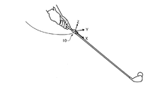
スイング分析装置1を分離型で構成する場合には、モーションセンサー10を、スイング動作に応じて発生する角速度を検出可能な任意の位置に取り付ければよい。例えば、モーションセンサー10は、図2(A)に示すようにゴルフクラブ等のスイング器具に取り付けられる。ただし、インパクト時の衝撃の影響を受けないように、図示のようにシャフトに取り付けるのが好ましい。それ以外にも、図2(B)に示すようにユーザーの手やグローブなどに取り付けられてもよいし、図2(C)に示すように腕時計などのアクセサリーに取り付けられてもよい。
When the swing analyzer 1 is configured as a separation type, the
また、スイング分析装置1を一体型で構成する場合には、スイング分析装置1自体をゴルフクラブ等のスイング器具、ユーザーの手やグローブ、アクセサリーなどに取り付けてもよい。 When the swing analyzer 1 is configured as an integral type, the swing analyzer 1 itself may be attached to a swing device such as a golf club, a user's hand, a glove, an accessory, or the like.
2.スイング分析装置の処理
2−1.スイング分析の全体処理
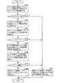
図3は、スイング分析装置1の処理部20によるスイング分析の全体処理の一例を示すフローチャート図である。
2. 2. Processing of swing analyzer 2-1. Overall Process of Swing Analysis FIG. 3 is a flowchart showing an example of the overall process of swing analysis by the
図3に示すように、本実施形態の処理部20は、まず、データ取得部22として機能し、モーションセンサー10から検出データを取得する(S10、データ取得ステップ)。データ取得部22がモーションセンサー10からデータを取得する期間(データ取得期間)は、何らかの方法で設定する。例えば、ユーザーあるいは補助者が、スイング開始前に操作部30を操作することでデータ取得期間の開始タイミングを指示し、スイング終了後に操作部30を操作することでデータ取得期間の終了タイミングを指示するようにしてもよい。また、例えば、ユーザーあるいは補助者が、スイング開始前に操作部30を操作することでデータ取得期間の開始タイミングを指示し、所定時間経過後に自動的にデータ取得期間を終了するようにしてもよい。
As illustrated in FIG. 3, the
次に、処理部20は、動作検出部24として機能し、ステップS10で取得したすべてのデータをリズム検出の対象範囲に設定し(S12)、リズム検出の対象範囲に設定されたデータ(すなわち取得した全データ)に対してリズム検出を行う(S14、リズム検出ステップ)。なお、リズムとは、スイングの開始からスイングの終了までの一連の動作のことを言い、例えば、ゴルフスイングの場合、スイングの開始から、バックスイング、トップ、ダウンスイング、インパクト、フォロースルー、スイングの終了までの一連の動作に相当する。
Next, the
ステップS14でリズム検出がされなかった場合(S16のN)は、取得したデータにスイング動作に対応するデータ(スイングデータ)が含まれていなかった判断して処理を終了する。この場合、取得したデータにスイングデータが含まれなかったことを表示部40に表示するようにしてもよい。
If the rhythm is not detected in step S14 (N in S16), it is determined that the data (swing data) corresponding to the swing motion is not included in the acquired data, and the process ends. In this case, it may be displayed on the
一方、ステップS14でリズム検出がされた場合(S16のY)、処理部20は、スイングデータ判定部26として機能し、ステップS14でリズム検出されたデータ(スイング候補データ)がユーザーのスイング動作に対応するスイングデータか否かを判定する(S18、スイングデータ判定ステップ)。
On the other hand, when the rhythm is detected in step S14 (Y in S16), the
ステップS18でスイング候補データがスイングデータであると判定された場合(S20のY)、処理部20は、表示処理部28として機能し、スイングデータのリズムを表示部40に表示し(S22、リズム表示ステップ)、処理を終了する。
When it is determined in step S18 that the swing candidate data is swing data (Y in S20), the
一方、ステップS18でスイング候補データがスイングデータでないと判定された場合(S20のN)は、処理部20は、リズム検出の対象範囲を設定し直して、再度、ステップS14以降の処理を行う。
On the other hand, when it is determined in step S18 that the swing candidate data is not swing data (N in S20), the
2−2.リズム検出処理
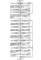
図4は、処理部20(動作検出部24)によるリズム検出処理の一例を示すフローチャート図である。
2-2. Rhythm Detection Processing FIG. 4 is a flowchart showing an example of rhythm detection processing by the processing unit 20 (motion detection unit 24).
図4に示すように、処理部20(動作検出部24)は、1回目のリズム検出処理において(S100のY)、まず、角速度計算部240として機能し、リズム検出の対象範囲に設定されたデータ(以下、「リズム検出対象データ」という)に対して、各時刻tでの角速度のノルムn0(t)の値を計算する(S110)。角速度のノルム(角速度の大きさの和)の求め方の一例として「角速度の大きさの2乗の和の平方根」から求める方法がある。例えば、モーションセンサー10が3軸回りの角速度を検出し、リズム検出対象データに対して、各時刻tでの3軸分の検出データをx(t)、y(t)、z(t)とすると、角速度のノルムn0(t)は、次式(1)で計算される。
As shown in FIG. 4, in the first rhythm detection process (Y in S100), the processing unit 20 (motion detection unit 24) first functions as the angular
![]()
![]()
次に、処理部20(動作検出部24)は、リズム検出対象データに対して、各時刻tでの角速度のノルムn0(t)を所定範囲に正規化したノルムn(t)に変換する(S120)。具体的には、リズム検出対象データにおける角速度のノルムの最大値をmax(n0)とすると、次式(2)により、角速度のノルムn0(t)が0〜100の範囲に正規化したノルムn(t)に変換される。 Next, the processing unit 20 (motion detection unit 24) converts the norm n 0 (t) of the angular velocity at each time t into a norm n (t) normalized to a predetermined range with respect to the rhythm detection target data. (S120). Specifically, assuming that the maximum value of the norm of the angular velocity in the rhythm detection target data is max (n 0 ), the norm n 0 (t) of the angular velocity is normalized to a range of 0 to 100 by the following equation (2). Converted to norm n (t).

次に、処理部20(動作検出部24)は、ノルム微分計算部242として機能し、各時刻tでのノルム(正規化後のノルムn(t))の微分の値を計算する(S130)。例えば、リズム検出対象データの取得間隔をΔtとすると、時刻tでの角速度のノルムの微分(差分)dn(t)は次式(3)で計算される。
Next, the processing unit 20 (motion detection unit 24) functions as a norm
![]()
![]()
一方、2回目以降のリズム検出処理(S100のN)では、ステップS110〜S130の処理は行われない。 On the other hand, in the second and subsequent rhythm detection processes (N in S100), the processes in steps S110 to S130 are not performed.
次に、処理部20(動作検出部24)は、インパクト検出部244として機能し、ノルムの微分dn(t)の値が最大となる時刻と最小となる時刻のうち、先の時刻をインパクト(最大インパクト)の時刻T5として設定する(S140)。通常のゴルフスイングでは、インパクトの瞬間にスイング速度が最大になると考えられる。そして、スイング速度に応じて角速度のノルムの値も変化すると考えられるので、一連のスイング動作の中で角速度のノルムの微分値が最大又は最小となるタイミング(すなわち、角速度のノルムの微分値が正の最大値又は負の最小値になるタイミング)をインパクトのタイミングとして捉えることができる。なお、インパクトによりゴルフクラブが振動するため、角速度のノルムの微分値が最大となるタイミングと最小となるタイミングが対になって生じると考えられるが、そのうちの先のタイミングがインパクトの瞬間と考えられる。
Next, the processing unit 20 (the motion detection unit 24) functions as the
次に、処理部20(動作検出部24)は、インパクトの時刻T5より前でノルムn(t)の値が0に近づく極小点が存在するか否かを判定し(S150)、存在すれば(S150のY)、当該極小点の時刻をトップの時刻T3として設定する(S152)。通常のゴルフスイングでは、スイング開始後、トップで一旦動作が止まり、その後、徐々にスイング速度が大きくなってインパクトに至ると考えられる。従って、インパクトのタイミングより前で角速度のノルムが0に近づき極小となるタイミングをトップのタイミングとして捉えることができる。 Next, the processing unit 20 (motion detection unit 24) determines whether or not there is a minimum point where the value of the norm n (t) approaches 0 before the impact time T5 (S150). (Y of S150), the time of the local minimum point is set as the top time T3 (S152). In a normal golf swing, it is considered that after the start of the swing, the operation is temporarily stopped at the top, and then the swing speed is gradually increased to cause an impact. Therefore, the timing at which the norm of the angular velocity approaches 0 and becomes the minimum before the impact timing can be regarded as the top timing.
一方、インパクトの時刻T5より前でノルムn(t)の値が0に近づく極小点が存在しなければ(S150のN)、処理部20(動作検出部24)は、リズム検出対象データに対するリズム検出に失敗した(リズム検出対象データにはスイング候補データが含まれていない)として処理を終了する。 On the other hand, if there is no minimum point where the value of norm n (t) approaches 0 before the impact time T5 (N in S150), the processing unit 20 (motion detection unit 24) performs a rhythm for the rhythm detection target data. The processing is terminated because the detection has failed (the swing target data is not included in the rhythm detection target data).
次に、処理部20(動作検出部24)は、インパクトの時刻T5より後でノルムn(t)の値が0に近づく極小点が存在するか否かを判定し(S154)、存在すれば(S154のY)、当該極小点の時刻をフィニッシュの時刻T7として設定する(S156)。通常のゴルフスイングでは、インパクトの後、徐々にスイング速度が小さくなって止まると考えられる。従って、インパクトのタイミングより後で角速度のノルムが0に近づき極小となるタイミングをフィニッシュのタイミングとして捉えることができる。 Next, the processing unit 20 (motion detecting unit 24) determines whether or not there is a minimum point whose norm n (t) approaches 0 after the impact time T5 (S154). (Y in S154), the time of the minimum point is set as the finish time T7 (S156). In a normal golf swing, it is considered that the swing speed gradually decreases after impact and stops. Therefore, the timing at which the norm of the angular velocity approaches 0 and becomes the minimum after the impact timing can be regarded as the finish timing.
一方、インパクトの時刻T5より後でノルムn(t)の値が0に近づく極小点が存在しなければ(S154のN)、処理部20(動作検出部24)は、リズム検出対象データに対するリズム検出に失敗した(リズム検出対象データにはスイング候補データが含まれていない)として処理を終了する。 On the other hand, if there is no minimum point at which the value of norm n (t) approaches 0 after the impact time T5 (N in S154), the processing unit 20 (motion detection unit 24) performs a rhythm for the rhythm detection target data. The processing is terminated because the detection has failed (the swing target data is not included in the rhythm detection target data).
次に、処理部20(動作検出部24)は、トップの時刻T3の前後でノルムn(t)の値があらかじめ設定された閾値以下の区間が存在するか否かを判定し(S158)、存在すれば(S158のY)、当該区間の最初と最後の時刻をそれぞれトップ区間の開始時刻T2と終了時刻T4として設定する(S160)。通常のゴルフスイングでは、トップで一旦動作が止まるので、トップの前後ではスイング速度が小さいと考えられる。従って、トップのタイミングを含み角速度のノルムが所与の閾値以下の連続した区間をトップ区間として捉えることができる。 Next, the processing unit 20 (motion detection unit 24) determines whether or not there is a section in which the value of the norm n (t) is equal to or less than a preset threshold value before and after the top time T3 (S158). If it exists (Y in S158), the first and last times of the section are set as the start time T2 and end time T4 of the top section, respectively (S160). In a normal golf swing, the operation stops once at the top, so it is considered that the swing speed is low before and after the top. Therefore, a continuous section including the timing of the top and having a norm of angular velocity equal to or less than a given threshold can be regarded as the top section.
一方、トップの時刻T3の前後でノルムn(t)の値が閾値以下の区間が存在しなければ(S158のN)、処理部20(動作検出部24)は、リズム検出対象データに対するリズム検出に失敗した(リズム検出対象データにはスイング候補データが含まれていない)として処理を終了する。 On the other hand, if there is no section in which the value of norm n (t) is equal to or less than the threshold before and after the top time T3 (N in S158), the processing unit 20 (motion detection unit 24) detects rhythm for the rhythm detection target data. The processing is terminated because it has failed (the swing target data is not included in the rhythm detection target data).
次に、処理部20(動作検出部24)は、フィニッシュの時刻T7の前後でノルムn(t)の値があらかじめ設定された閾値以下の区間が存在するか否かを判定し(S162)、存在すれば(S162のY)、当該区間の最初と最後の時刻をそれぞれフィニッシュ区間の開始時刻T6と終了時刻T8として設定する(S164)。通常のゴルフスイングでは、インパクトの後、徐々にスイング速度が小さくなって止まると考えられる。従って、フィニッシュのタイミングを含み角速度のノルムが所与の閾値以下の連続した区間をフィニッシュ区間として捉えることができる。 Next, the processing unit 20 (motion detection unit 24) determines whether or not there is a section in which the value of the norm n (t) is equal to or smaller than a preset threshold value before and after the finish time T7 (S162). If it exists (Y of S162), the first and last times of the section are set as the start time T6 and end time T8 of the finish section, respectively (S164). In a normal golf swing, it is considered that the swing speed gradually decreases after impact and stops. Therefore, a continuous section including the finish timing and the norm of the angular velocity being equal to or less than a given threshold value can be regarded as the finish section.
一方、フィニッシュの時刻T7の前後でノルムn(t)の値が閾値以下の区間が存在しなければ(S162のN)、処理部20(動作検出部24)は、リズム検出対象データに対するリズム検出に失敗した(リズム検出対象データにはスイング候補データが含まれていない)として処理を終了する。 On the other hand, if there is no section in which the value of norm n (t) is equal to or smaller than the threshold value before and after the finish time T7 (N in S162), the processing unit 20 (motion detection unit 24) detects the rhythm for the rhythm detection target data. The processing is terminated because it has failed (the swing target data is not included in the rhythm detection target data).
次に、処理部20(動作検出部24)は、トップ区間の開始時刻T2より前でノルムn(t)の値があらかじめ設定された閾値(第2閾値の一例)以下となるか否かを判定し(S166)、閾値以下となれば(S166のY)、当該閾値以下になる最後の時刻をスイング開始の時刻T1として設定する(S168)。なお、トップを特定する極小点より前で、ノルムが0に近づく極小点をスイング開始とみなしても良い。通常のゴルフスイングでは、静止した状態からスイング動作を開始し、トップまでにスイング動作が止まることは考えにくい。従って、トップのタイミングより前で角速度のノルムが閾値以下となる最後のタイミングをスイング動作の開始のタイミングとして捉えることができる。 Next, the processing unit 20 (motion detection unit 24) determines whether or not the value of the norm n (t) is equal to or less than a preset threshold (an example of a second threshold) before the start time T2 of the top section. If it is determined (S166) and if it is equal to or less than the threshold value (Y in S166), the last time that is equal to or less than the threshold value is set as the swing start time T1 (S168). Note that a minimum point whose norm approaches 0 before the minimum point specifying the top may be regarded as a swing start. In a normal golf swing, it is unlikely that the swing operation starts from a stationary state and stops until the top. Therefore, the last timing when the norm of the angular velocity is equal to or less than the threshold before the top timing can be regarded as the timing for starting the swing motion.
一方、トップ区間の開始時刻T2より前でノルムn(t)の値が閾値以下とならなければ(S166のN)、処理部20(動作検出部24)は、リズム検出対象データに対するリズム検出に失敗した(リズム検出対象データにはスイング候補データが含まれていない)として処理を終了する。 On the other hand, if the value of the norm n (t) is not less than the threshold value before the start time T2 of the top section (N in S166), the processing unit 20 (motion detection unit 24) performs rhythm detection on the rhythm detection target data. The process is terminated because it has failed (the rhythm detection target data does not include swing candidate data).
最後に、処理部20(動作検出部24)は、リズム検出されたT1〜T8のデータをスイング候補データとし(S170)、処理を終了する。 Finally, the processing unit 20 (motion detection unit 24) uses the data of T1 to T8 detected for rhythm as swing candidate data (S170), and ends the process.
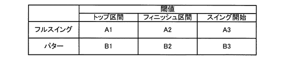
トップ区間、フィニッシュ区間、スイング開始の各閾値は、例えば、図5に示すようなテーブルデータとしてROM50やRAM60などに記憶される。これらの閾値は、固定値でもよいし、可変値(例えば、ユーザー毎に個別に設定)でもよい。図5のように、各動作に対応して各閾値を設けておけば、極小点が複数発生した場合においても、スイングに対応した極小点の抽出が容易となる。
The threshold values for the top section, the finish section, and the swing start are stored in, for example, the
なお、図4のフローチャートの各ステップを適宜入れ替えてもよい。 Note that each step of the flowchart of FIG. 4 may be appropriately replaced.
また、図4のフローチャートにおいて、各時刻tでのノルム(正規化後のノルム)n(t)の微分dn(t)の値を計算する工程(S130)は省略することが可能である。特にドライバーのスイングのように角速度のノルムの変化が大きいものについては微分工程(S130)は省略することができる。S130を省略する場合は、S120で求めた角速度のノルムの最大値をインパクト(最大インパクト)のタイミングとして検出すれば良い。 Further, in the flowchart of FIG. 4, the step (S130) of calculating the value of the differential dn (t) of the norm (norm after normalization) n (t) at each time t can be omitted. In particular, the differentiation step (S130) can be omitted for a driver whose swing has a large change in norm of angular velocity, such as a driver's swing. When S130 is omitted, the maximum value of the norm of the angular velocity obtained in S120 may be detected as the impact (maximum impact) timing.
また、図4のフローチャートのステップS154、S156において、インパクトのタイミングより後で角速度のノルムn(t)の値が0に近づく極小点をフィニッシュのタイミングとしているが、例えば、インパクトより後で、角速度のノルムn(t)の値があらかじめ設定された閾値(第3閾値の一例)以下となる最初のタイミングをスイングのフィニッシュのタイミングとして設定してもよい。 Further, in steps S154 and S156 of the flowchart of FIG. 4, the minimum point at which the value of the norm n (t) of the angular velocity approaches 0 after the impact timing is set as the finish timing. The first timing when the value of the norm n (t) is equal to or less than a preset threshold (an example of a third threshold) may be set as the swing finish timing.
また、図4のフローチャートでは、スイングの開始から、バックスイング、トップ、ダウンスイング、インパクト、フォロースルー、スイングの終了までのすべての動作を検出しているが、例えば、インパクトとダウンスイングだけの動作を検出するなどスイング動作の少なくとも1つの動作を検出するようにしてもよい。 In the flowchart of FIG. 4, all the operations from the start of the swing to the back swing, top, down swing, impact, follow-through, and end of the swing are detected. For example, only the impact and the down swing are detected. It is also possible to detect at least one motion of the swing motion, such as detecting.
2−3.スイングデータ判定処理
図6は、処理部20(スイングデータ判定部26)によるスイングデータ判定処理の一例を示すフローチャート図である。
2-3. Swing Data Determination Process FIG. 6 is a flowchart showing an example of the swing data determination process by the processing unit 20 (swing data determination unit 26).
図6に示すように、処理部20(スイングデータ判定部26)は、まず、スイング候補データにおいて、スイング開始の時刻T1からフィニッシュ区間の終了時刻T8までのインパクトの数を算出する(S200)。ここでいうインパクトとは、ゴルフクラブがボールに当たるインパクト(最大インパクト)だけでなく、ゴルフクラブが地面や障害物などに当たるインパクトも含まれる。例えば、処理部20(スイングデータ判定部26)は、角速度のノルムの微分(差分)dn(t)があらかじめ設定した閾値を横切って超える回数をインパクトの数として算出する。 As shown in FIG. 6, the processing unit 20 (swing data determination unit 26) first calculates the number of impacts from the swing start time T1 to the finish section end time T8 in the swing candidate data (S200). The impact referred to here includes not only the impact (maximum impact) of the golf club hitting the ball, but also the impact of the golf club hitting the ground or an obstacle. For example, the processing unit 20 (swing data determination unit 26) calculates, as the number of impacts, the number of times that the differential (difference) dn (t) of the norm of angular velocity exceeds a preset threshold value.
スイング開始の時刻T1からフィニッシュ区間の終了時刻T8までに含まれるインパクトが1つのみであれば(S210のY)、処理部20(スイングデータ判定部26)は、バックスイングの時間Ta=トップの時刻T3−スイング開始の時刻T1を計算し(S220)、さらに、ダウンスイングの時間Tc=インパクトの時刻T5−トップの時刻T3を計算する(S230)。 If only one impact is included from the swing start time T1 to the finish section end time T8 (Y in S210), the processing unit 20 (swing data determination unit 26) determines that the backswing time Ta = top. Time T3—Swing start time T1 is calculated (S220), and further, downswing time Tc = impact time T5—top time T3 is calculated (S230).
一方、スイング開始の時刻T1からフィニッシュ区間の終了時刻T8までに含まれるインパクトが2つ以上あれば(S210のN)、処理部20(スイングデータ判定部26)は、当該スイング候補データが真のスイングデータではないと判定し、リズム検出の対象範囲から時刻T8以前のデータを除外した残りのデータを新たなリズム検出の対象範囲に設定する(S290)。通常のスイング動作では、スイングの開始から終了までにインパクトが1つであると考えられるので、スイング候補データの期間にインパクトのタイミングが1つでなければ当該スイング候補データは真のスイングデータではないと判定することができる。 On the other hand, if there are two or more impacts included from the swing start time T1 to the finish section end time T8 (N in S210), the processing unit 20 (swing data determination unit 26) determines that the swing candidate data is true. It is determined that the data is not swing data, and the remaining data obtained by excluding data before time T8 from the rhythm detection target range is set as a new rhythm detection target range (S290). In a normal swing operation, it is considered that there is only one impact from the start to the end of the swing. Therefore, the swing candidate data is not true swing data unless there is one impact timing in the period of the swing candidate data. Can be determined.
そして、バックスイングの時間Taがダウンスイングの時間Tcよりも短ければ(S240のY)、処理部20(スイングデータ判定部26)は、トップ区間の時間Tb=トップ区間の終了時刻T4−トップ区間の開始時刻T2を計算し(S250)、さらに、スイング候補データの全時間T=フィニッシュ区間の終了時刻T8−スイング開始の時刻T1を計算する(S260)。 If the backswing time Ta is shorter than the downswing time Tc (Y in S240), the processing unit 20 (swing data determination unit 26) determines that the top section time Tb = top section end time T4-top section. Start time T2 is calculated (S250), and the total time T of the swing candidate data T = finishing end time T8−swing start time T1 is calculated (S260).
一方、バックスイングの時間Taがダウンスイングの時間Tc以上であれば(S240のN)、処理部20(スイングデータ判定部26)は、当該スイング候補データが真のスイングデータではないと判定し、リズム検出の対象範囲から時刻T8以前のデータを除外した残りのデータを新たなリズム検出の対象範囲に設定する(S290)。通常のスイング動作では、ダウンスイングの時間がバックスイングの時間よりも短いと考えられるので、スイング候補データにおけるダウンスイングの時間Tcがバックスイングの時間Ta以上であれば当該スイング候補データは真のスイングデータではないと判定することができる。 On the other hand, if the backswing time Ta is equal to or longer than the downswing time Tc (N in S240), the processing unit 20 (swing data determination unit 26) determines that the swing candidate data is not true swing data, The remaining data obtained by excluding data before time T8 from the rhythm detection target range is set as a new rhythm detection target range (S290). In a normal swing operation, it is considered that the downswing time is shorter than the backswing time. Therefore, if the downswing time Tc in the swing candidate data is equal to or longer than the backswing time Ta, the swing candidate data is a true swing. It can be determined that it is not data.
最後に、処理部20(スイングデータ判定部26)は、(トップ区間の時間Tb/スイング候補データの全時間T)の値を計算し、Tb/Tの値があらかじめ設定された閾値(第1閾値の一例)以下であれば(S270のY)、当該スイング候補データ(T1〜T8のデータ)を真のスイングデータと決定し(S280)、処理を終了する。 Finally, the processing unit 20 (swing data determination unit 26) calculates a value of (the time Tb of the top section / the total time T of the swing candidate data), and a threshold (first value) in which the value of Tb / T is set in advance. (Example of threshold value) If less than (Y in S270), the swing candidate data (data of T1 to T8) is determined as true swing data (S280), and the process is terminated.
一方、Tb/Tの値が閾値以下でなければ(S270のN)、処理部20(スイングデータ判定部26)は、当該スイング候補データが真のスイングデータではないと判定し、リズム検出の対象範囲から時刻T8以前のデータを除外した残りのデータを新たなリズム検出の対象範囲に設定する(S290)。通常のスイング動作では、トップ区間の時間と全時間との比が所定範囲であると考えられるので、スイング候補データにおけるTb/Tの値が閾値以下でなければ当該スイング候補データは真のスイングデータではないと判定することができる。例えば、真のスイングデータであればTb/Tの値が0.15(=15%)を超えることはないと考えられるので、閾値を0.15(=15%)に設定することができる。 On the other hand, if the value of Tb / T is not less than or equal to the threshold value (N in S270), the processing unit 20 (swing data determination unit 26) determines that the swing candidate data is not true swing data, and targets for rhythm detection The remaining data obtained by excluding data before time T8 from the range is set as a new rhythm detection target range (S290). In a normal swing operation, the ratio between the time of the top section and the total time is considered to be within a predetermined range. Therefore, if the value of Tb / T in the swing candidate data is not less than the threshold value, the swing candidate data is true swing data. It can be determined that it is not. For example, since it is considered that the value of Tb / T does not exceed 0.15 (= 15%) for true swing data, the threshold value can be set to 0.15 (= 15%).
なお、図6のフローチャートの各ステップを適宜入れ替えてもよい。 Note that the steps in the flowchart of FIG. 6 may be appropriately replaced.
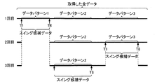
モーションセンサー10から取得した全データの中にスイング候補データとなる複数のデータパターンが含まれる場合は、スイングデータが検出されるか、あるいはすべてのデータパターンがスイングデータでないと判定されるまで、図4のリズム検出処理と図6のスイングデータ判定処理が繰り返し行われる。例えば、モーションセンサー10から取得した全データの中にスイング候補データとなる3つのデータパターン(時系列順にデータパターン1、データパターン2、データパターン3)が含まれ、最後のデータパターン3がスイングデータであるとする。この場合、図7に示すように、1回目はモーションセンサー10から取得した全データをリズム検出対象データとしてリズム検出処理を行い、例えばデータパターン1がスイング候補データとして検出される。そして、このデータパターン1はスイングデータではないので、1回目のリズム検出対象データからデータパターン1を削除した残りのデータに対して2回目のリズム検出を行う。2回目のリズム検出処理で例えばデータパターン2が検出されると、このデータパターン2もスイングデータではないので、2回目のリズム検出対象データからデータパターン2を削除した残りのデータに対して3回目のリズム検出を行う。3回目のリズム検出処理でデータパターン3が検出され、このデータパターン3がスイングデータと判定される。
If a plurality of data patterns serving as swing candidate data are included in all the data acquired from the
2−4.リズム表示処理
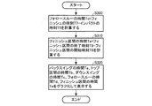
図8は、処理部20(表示処理部28)によるリズム表示処理の一例を示すフローチャート図である。
2-4. Rhythm Display Processing FIG. 8 is a flowchart showing an example of rhythm display processing by the processing unit 20 (display processing unit 28).
まず、処理部20(表示処理部28)は、スイングデータに対して、フォロースルーの時間Td=フィニッシュの時刻T7−インパクトの時刻T5を計算する(S300)。 First, the processing unit 20 (display processing unit 28) calculates a follow-through time Td = finish time T7−impact time T5 for the swing data (S300).
次に、処理部20(表示処理部28)は、フィニッシュ区間の時間Te=フィニッシュ区間の終了時刻T8−フィニッシュ区間の開始時刻T6を計算する(S310)。 Next, the processing unit 20 (display processing unit 28) calculates finish section time Te = finish section end time T8-finish section start time T6 (S310).
最後に、処理部20(表示処理部28)は、図6のステップS220、S250、S230、図8のステップS300、S310でそれぞれ計算した各フェーズの時間(バックスイングの時間Ta、トップ区間の時間Tb、ダウンスイングの時間Tc、フォロースルーの時間Td、フィニッシュ区間の時間Te)をグラフ化して表示部40に表示する(S320)。 Finally, the processing unit 20 (display processing unit 28) performs the time of each phase (backswing time Ta, time of the top section) calculated in steps S220, S250, S230 of FIG. 6 and steps S300, S310 of FIG. Tb, downswing time Tc, follow-through time Td, and finish section time Te) are graphed and displayed on the display unit 40 (S320).
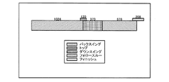
図9は、スイング動作のリズム表示の一例を示す図である。図9の表示例では、スイング動作における各フェーズ(バックスイング、トップ区間、ダウンスイング、フォロースルー、フィニッシュ区間)を、それぞれの時間Ta,Tb,Tc,Td,Teに比例した長さで固有の色あるいは模様を有する矩形で時系列に沿って表示している。また、各フェーズの矩形表示の上側にそれぞれの時間Ta,Tb,Tc,Td,Teを表示している。このようなリズム表示により、ユーザーは、例えば、トップ区間Tbが短いからトップでの溜めが足りない、ダウンスイングの時間Tcが長いからインパクトが弱いというような自己のスイング動作のリズムに関する詳細な情報を得ることができる。また、スイングのリズムを全て表示させるだけでなく、スイングの各動作ごとに時間を表示しても良い。 FIG. 9 is a diagram illustrating an example of a rhythm display of a swing operation. In the display example of FIG. 9, each phase (back swing, top section, down swing, follow-through, finish section) in the swing operation is inherent in a length proportional to each time Ta, Tb, Tc, Td, Te. A rectangle having a color or pattern is displayed in time series. Also, the respective times Ta, Tb, Tc, Td, Te are displayed on the upper side of the rectangular display of each phase. With such a rhythm display, the user can, for example, provide detailed information on the rhythm of his / her swing motion such that the top section Tb is short and there is not enough storage at the top, and the downswing time Tc is long and the impact is weak. Can be obtained. In addition to displaying all the rhythm of the swing, the time may be displayed for each operation of the swing.
3.実験例
図10〜図14は、本実施形態のスイング分析装置1を用いたスイング動作のリズム分析の実験例に関する図である。
3. Experimental example FIGS. 10-14 is a figure regarding the experimental example of the rhythm analysis of the swing operation | movement using the swing analyzer 1 of this embodiment.
図10に示すように、本実験例では、ゴルフクラブ(ドライバー)のシャフトのグリップ近くに3軸の角速度を検出するモーションセンサー10を取り付け、被験者が1回だけスイングを行ってゴルフボールを打った時のリズムを分析した。モーションセンサー10は、x軸がシャフトに平行な方向、y軸がスイングの方向、z軸がスイング面と垂直な方向になるように取り付けた。ただし、本実施形態のスイング分析装置1は、角速度のノルムに基づいて各フェーズの時間を計算するので、モーションセンサー10の取り付け角は任意である。また、モーションセンサー10を、不図示のPC(処理部20、操作部30、表示部40、ROM50、RAM60、不揮発性メモリー70、記録媒体80などを備えている)とケーブルで接続し、PC側でモーションセンサー10が検出した一連の3軸角速度データをRAM60に取得し、取得したデータに含まれるスイングデータのリズムを分析して表示させた。
As shown in FIG. 10, in this experimental example, a
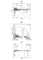
図11(A)は、被験者がドライバーを持ってすぐにフルスイングした時のデータ取得期間(5秒間)に取得されたデータから3軸の角速度x(t),y(t),z(t)をグラフ表示した図である。図11(A)において、横軸は時間(msec)、縦軸は角速度(dps)である。 FIG. 11A shows three-axis angular velocities x (t), y (t), and z (t) from data acquired during a data acquisition period (5 seconds) when the subject fully swings with the driver. ) In a graph. In FIG. 11A, the horizontal axis represents time (msec) and the vertical axis represents angular velocity (dps).
図11(B)は、図11(A)の3軸角速度x(t),y(t),z(t)から3軸角速度のノルムn0(t)を式(1)に従って計算した後に式(2)に従って0〜100にスケール変換(正規化)したノルムn(t)をグラフ表示した図である。図11(B)において、横軸は時間(msec)、縦軸は角速度のノルム(0〜100にスケール変換)である。 FIG. 11B shows the calculation of the norm n 0 (t) of the triaxial angular velocity x (t), y (t), z (t) in FIG. 11A according to the equation (1). It is the figure which displayed the norm n (t) scale-converted (normalized) to 0-100 according to Formula (2) graphically. In FIG. 11B, the horizontal axis represents time (msec), and the vertical axis represents the norm of angular velocity (scale conversion to 0 to 100).
図11(C)は、図11(B)の3軸角速度のノルムn(t)からその微分dn(t)を式(3)に従って計算し、グラフ表示した図である。図11(C)において、横軸は時間(msec)、縦軸は3軸角速度のノルムの微分値である。なお、図11(A)及び図11(B)では横軸を0〜5秒で表示しているが、図11(C)では、インパクトの前後の微分値の変化がわかるように、横軸を2秒〜2.8秒で表示している。 FIG. 11C is a graph showing the differential dn (t) calculated from the norm n (t) of the triaxial angular velocity in FIG. In FIG. 11C, the horizontal axis represents time (msec), and the vertical axis represents the differential value of the norm of the triaxial angular velocity. In FIGS. 11A and 11B, the horizontal axis is displayed in 0 to 5 seconds. In FIG. 11C, the horizontal axis is shown so that the change in the differential value before and after the impact can be seen. Is displayed in 2 seconds to 2.8 seconds.
図11(B)及び図11(C)より、図4に示したリズム検出処理のフローチャートに従ってスイング候補データを抽出し、スイング開始の時刻T1、トップ区間の開始時刻T2、トップの時刻T3、トップ区間の終了時刻T4、インパクトの時刻T5、フィニッシュ区間の開始時刻T6、フィニッシュの時刻T7、フィニッシュ区間の終了時刻T8を計算した。その結果、T1=1000msec,T2=1967msec,T3=2024msec,T4=2087msec,T5=2397msec,T6=3002msec,T7=3075msec,T8=3210msecであった。 11B and 11C, swing candidate data is extracted according to the flowchart of the rhythm detection process shown in FIG. 4, and the swing start time T1, the top section start time T2, the top time T3, the top A section end time T4, an impact time T5, a finish section start time T6, a finish time T7, and a finish section end time T8 were calculated. As a result, T1 = 1000 msec, T2 = 1967 msec, T3 = 2024 msec, T4 = 2087 msec, T5 = 2397 msec, T6 = 3002 msec, T7 = 3075 msec, T8 = 3210 msec.
次に、このスイングデータ候補のT1〜T8の計算値を用いて、図6に示したスイングデータ判定処理のフローチャートに従って、バックスイングの時間Ta、トップ区間の時間Tb、ダウンスイングの時間Tc、全時間Tを計算した。その結果、Ta=T3−T1=1024msec,Tb=T4−T2=120msec,Tc=T5−T3=373msec,T=T8−T1=2210msecであった。 Next, using the calculated values of the swing data candidates T1 to T8, the backswing time Ta, the top section time Tb, the downswing time Tc, and the total time according to the swing data determination processing flowchart shown in FIG. Time T was calculated. As a result, Ta = T3-T1 = 1024 msec, Tb = T4-T2 = 120 msec, Tc = T5-T3 = 373 msec, and T = T8-T1 = 2210 msec.
このスイング候補データが真のスイングデータであるか否かを判定すると、T1〜T8の間に1つのインパクト(時刻T5のインパクト)のみ存在し、かつ、Ta>Tc、かつ、Tb/T<閾値(例えば15%)を満たすので、スイングデータの条件を満たしている。 When it is determined whether the swing candidate data is true swing data, only one impact (impact at time T5) exists between T1 and T8, Ta> Tc, and Tb / T <threshold. (For example, 15%) is satisfied, so the condition of swing data is satisfied.
そこで、次に、図8に示したリズム表示処理に従い、フォロースルーの時間Td及びフィニッシュ区間の時間Teを計算すると、Td=T7−T5=678msec,Te=T8−T6=208msecであり、図12に示すリズム表示が得られた。 Accordingly, when the follow-through time Td and the finish section time Te are calculated in accordance with the rhythm display processing shown in FIG. 8, Td = T7−T5 = 678 msec, Te = T8−T6 = 208 msec, and FIG. The rhythm display shown in Fig. 1 was obtained.
これに対して、図13(A)は、被験者がドライバーを持ってスイング前にドライバーを動かした後フルスイングした時のデータ取得期間(約25秒間)に取得されたデータから3軸の角速度x(t),y(t),z(t)をグラフ表示した図である。図13(A)において、横軸は時間(msec)、縦軸は角速度(dps)である。 On the other hand, FIG. 13A shows the three-axis angular velocity x from the data acquired during the data acquisition period (about 25 seconds) when the subject moves the driver before the swing with the driver. It is the figure which displayed the graph of (t), y (t), z (t). In FIG. 13A, the horizontal axis represents time (msec) and the vertical axis represents angular velocity (dps).
図13(B)は、図13(A)の3軸角速度x(t),y(t),z(t)から3軸角速度のノルムn0(t)を式(1)に従って計算した後に式(2)に従って0〜100にスケール変換(正規化)したノルムn(t)をグラフ表示した図である。図13(B)において、横軸は時間(msec)、縦軸は角速度のノルム(0〜100にスケール変換)である。 FIG. 13B shows the calculation of the norm n 0 (t) of the triaxial angular velocity x (t), y (t), z (t) in FIG. 13A according to the equation (1). It is the figure which displayed the norm n (t) scale-converted (normalized) to 0-100 according to Formula (2) graphically. In FIG. 13B, the horizontal axis represents time (msec), and the vertical axis represents the norm of angular velocity (scale conversion from 0 to 100).
図13(C)は、図13(B)の3軸角速度のノルムn(t)からその微分dn(t)を式(3)に従って計算し、グラフ表示した図である。図13(C)において、横軸は時間(msec)、縦軸は3軸角速度のノルムの微分値である。 FIG. 13C is a graph showing the differential dn (t) calculated from the norm n (t) of the triaxial angular velocity in FIG. In FIG. 13C, the horizontal axis represents time (msec), and the vertical axis represents the differential value of the norm of the triaxial angular velocity.
図13(B)及び図13(C)より、図4に示したリズム検出処理のフローチャートに従ってスイング候補データを抽出し、スイング開始の時刻T1、トップ区間の開始時刻T2、トップの時刻T3、トップ区間の終了時刻T4、インパクトの時刻T5、フィニッシュ区間の開始時刻T6、フィニッシュの時刻T7、フィニッシュ区間の終了時刻T8を計算した。その結果、T1=307msec,T2=984msec,T3=998msec,T4=1019msec,T5=1982msec,T6=2092msec,T7=2100msec,T8=2109msecのスイング候補データが抽出された。 From FIG. 13B and FIG. 13C, swing candidate data is extracted according to the flowchart of the rhythm detection process shown in FIG. 4, and swing start time T1, top section start time T2, top time T3, top A section end time T4, an impact time T5, a finish section start time T6, a finish time T7, and a finish section end time T8 were calculated. As a result, swing candidate data of T1 = 307 msec, T2 = 984 msec, T3 = 998 msec, T4 = 1019 msec, T5 = 1982 msec, T6 = 2092 msec, T7 = 2100 msec, T8 = 2109 msec was extracted.
次に、この1回目のスイングデータ候補のT1〜T8の計算値を用いて、図6に示したスイングデータ判定処理のフローチャートに従って、バックスイングの時間Ta、トップ区間の時間Tb、ダウンスイングの時間Tc、全時間Tを計算した。その結果、Ta=T3−T1=691msec,Tb=T4−T2=35msec,Tc=T5−T3=984msec,T=1802msecであった。 Next, using the calculated values of T1 to T8 of the first swing data candidate, according to the swing data determination processing flowchart shown in FIG. 6, the backswing time Ta, the top section time Tb, and the downswing time Tc, total time T was calculated. As a result, Ta = T3-T1 = 691 msec, Tb = T4-T2 = 35 msec, Tc = T5-T3 = 984 msec, and T = 1802 msec.
この1回目のスイング候補データが真のスイングデータであるか否かを判定すると、T1〜T8の間に2つのインパクト(時刻Txのインパクトと時刻T5のインパクト)が存在し、また、Ta<Tcなので、スイングデータの条件を満たしていない。 When it is determined whether or not the first swing candidate data is true swing data, there are two impacts (impact at time Tx and impact at time T5) between T1 and T8, and Ta <Tc. Therefore, it does not meet the conditions of swing data.
従って、1回目のスイング候補データは、真のスイングデータではないと判断し、全データから時刻T8以前のデータを削除した残りのデータに対して、2回目のリズム検出処理を行ってスイング候補データを抽出し、T1〜T8を計算した。その結果、T1=18324msec,T2=18976msec,T3=18997msec,T4=19018msec,T5=19233msec,T6=19746msec,T7=19891msec,T8=20902msecのスイング候補データが抽出された。 Therefore, it is determined that the first swing candidate data is not true swing data, and the second rhythm detection process is performed on the remaining data obtained by deleting the data before time T8 from all the data, thereby performing the swing candidate data. Was extracted and T1 to T8 were calculated. As a result, swing candidate data of T1 = 18324 msec, T2 = 18976 msec, T3 = 18997 msec, T4 = 190118 msec, T5 = 19233 msec, T6 = 19746 msec, T7 = 19891 msec, T8 = 20902 msec was extracted.
次に、この2回目のスイングデータ候補のT1〜T8の計算値を用いて、Ta,Tb,Tc,Tを計算した結果、Ta=673msec,Tb=42msec,Tc=236msec,T=2578msecであった。 Next, Ta, Tb, Tc, and T were calculated using the calculated values of T1 to T8 of the second swing data candidate. As a result, Ta = 673 msec, Tb = 42 msec, Tc = 236 msec, and T = 2578 msec. It was.
そして、2回目のスイング候補データが真のスイングデータであるか否かを判定すると、T1〜T8の間に1つのインパクト(時刻T5のインパクト)のみ存在し、かつ、Ta>Tc、かつ、Tb/T<閾値(例えば15%)を満たすので、スイングデータの条件を満たしている。 When it is determined whether or not the second swing candidate data is true swing data, only one impact (impact at time T5) exists between T1 and T8, and Ta> Tc and Tb. Since / T <threshold value (for example, 15%) is satisfied, the condition of swing data is satisfied.
そこで、次に、図8に示したリズム表示処理に従い、フォロースルーの時間Td及びフィニッシュ区間の時間Teを計算すると、Td=658msec,Te=1156msecであり、図14に示すリズム表示が得られた。このように、ユーザーがスイング動作の前に自由な動きをしたとしてもスイングデータが正しく選別され、スイング動作の詳細なリズムのデータが得られた。 Therefore, when the follow-through time Td and the finish section time Te are calculated according to the rhythm display process shown in FIG. 8, Td = 658 msec and Te = 1156 msec, and the rhythm display shown in FIG. 14 is obtained. . As described above, even if the user freely moves before the swing motion, the swing data is correctly selected, and detailed rhythm data of the swing motion is obtained.
なお、図11、図13の例において、前述したように、各時刻tでのノルム(正規化後のノルム)n(t)の微分dn(t)の値を計算する工程(S130)は省略することが可能である。特に図ドライバーのスイングのように角速度のノルムの変化が大きいものについては微分工程(S130)は省略することができる。微分工程を省略する場合は、S120で求めた角速度のノルム(図11(b)、図12(b))の最大値を最大インパクトのタイミングとして検出すれば良い。 In the examples of FIGS. 11 and 13, as described above, the step (S130) of calculating the value of the differential dn (t) of the norm (norm after normalization) n (t) at each time t is omitted. Is possible. In particular, the differentiation step (S130) can be omitted for the case where the change in the norm of the angular velocity is large, such as the swing of the figure driver. When omitting the differentiation step, the maximum value of the norm of angular velocity (FIG. 11B, FIG. 12B) obtained in S120 may be detected as the timing of maximum impact.
以上に説明したように、本実施形態によれば、モーションセンサー10から取得した検出データからスイング候補データを抽出し、スイング候補データがスイングデータであるか否かを判定するので、ユーザーがスイング動作の開始や終了のタイミングを指示する必要がない。従って、ユーザーは、スイング前後に自由な動作を行うことができ、自然な動きの中でスイングを分析することができる。
As described above, according to the present embodiment, the swing candidate data is extracted from the detection data acquired from the
また、本実施形態によれば、検出したリズムの妥当性を評価することによりスイング候補データがスイングデータであるか否かを判定するので、波形のパターンマッチングを行う場合と比較して、より小さい計算負荷でスイングデータを抽出することができる。 Further, according to the present embodiment, it is determined whether or not the swing candidate data is swing data by evaluating the validity of the detected rhythm, so that it is smaller than when performing waveform pattern matching. Swing data can be extracted with a calculation load.
また、本実施形態によれば、モーションセンサー10として角速度センサーを用いることで、加速度センサーを用いた場合と比較してスイング動作をより正確に検出するとともに、動きの小さいスイングも検出可能である。従って、例えば、トップとフィニッシュでゴルフクラブをどの程度緩やかに留めているかなど、より詳細な分析をすることができる。また、インパクトを基準にして、スイングの開始から、バックスイング、トップ、ダウンスイング、フォロースルー、スイングの終了までの各動作の少なくとも1つを検出することが可能となる。
Further, according to the present embodiment, by using an angular velocity sensor as the
また、本実施形態によれば、角速度のノルムに基づいてスイング動作を検出するので、スイング動作に連動して動く場所に任意の向きにモーションセンサー10を取り付けることができ、取り扱いが容易である。
Further, according to the present embodiment, since the swing motion is detected based on the norm of the angular velocity, the
また、本実施形態によれば、角速度のノルムの値が急激に変化するため一連のスイング動作の中で最も捉えやすいインパクトのタイミングを最初に検出し、インパクトのタイミングに基づいてスイング動作の各フェーズを特定することで、より確実にスイング動作の検出を行うことができる。 Further, according to the present embodiment, since the norm value of the angular velocity changes abruptly, the impact timing that is most easily captured in a series of swing motions is detected first, and each phase of the swing motion is determined based on the impact timing. By specifying, swing motion can be detected more reliably.
また、本実施形態によれば、スイング動作の各フェーズの時間を表示するので、ユーザーはスイング動作の詳細なリズムを容易に把握することができる。 Further, according to the present embodiment, since the time of each phase of the swing operation is displayed, the user can easily grasp the detailed rhythm of the swing operation.
4,変形例
本発明は本実施形態に限定されず、本発明の要旨の範囲内で種々の変形実施が可能である。例えば、以下のような変形例が考えられる。
4. Modifications The present invention is not limited to this embodiment, and various modifications can be made within the scope of the present invention. For example, the following modifications can be considered.
[変形例1]
図15は、変形例1におけるスイングデータ判定処理を示すフローチャート図である。図15において、図6と同じ処理には同じ符号を付している。図15に示すように、変形例1におけるスイングデータ判定処理では、スイング候補データがスイングデータではないと判定した場合(S210のN、S240のN又はS270のN)、リズム検出の対象範囲から当該スイング候補データ(時刻T1〜T8のデータ)を除外した残りのデータを新たなリズム検出の対象範囲に設定する(S292)。図15におけるその他の処理については図6と同じである。
[Modification 1]
FIG. 15 is a flowchart illustrating the swing data determination process in the first modification. In FIG. 15, the same processes as those in FIG. As shown in FIG. 15, in the swing data determination process in the first modification, when it is determined that the swing candidate data is not the swing data (N in S210, N in S240, or N in S270), The remaining data excluding the swing candidate data (data at times T1 to T8) is set as a new rhythm detection target range (S292). Other processes in FIG. 15 are the same as those in FIG.
例えば、モーションセンサー10から取得した全データの中にスイング候補データとなる3つのデータパターン(時系列順にデータパターン1、データパターン2、データパターン3)が含まれ、2番目のデータパターン2がスイングデータであるとする。この場合、図16に示すように、1回目はモーションセンサー10から取得した全データをリズム検出対象データとしてリズム検出処理を行い、例えばデータパターン1がスイング候補データとして検出される。そして、このデータパターン1は真のスイングデータではないので、1回目のリズム検出対象データからデータパターン1を削除した残りのデータに対して2回目のリズム検出を行う。2回目のリズム検出処理で例えばデータパターン3が検出されると、このデータパターン3も真のスイングデータではないので、2回目のリズム検出対象データからデータパターン3を削除した残りのデータに対して3回目のリズム検出を行う。3回目のリズム検出処理でデータパターン2が検出され、このデータパターン2が真のスイングデータと判定される。
For example, all data acquired from the
このように、本変形例によれば、ユーザーがスイング動作の前だけでなく、スイング動作の後に大きなインパクトを生じさせるような動きをしても、確実にスイング動作を検出することができる。 Thus, according to the present modification, the swing motion can be reliably detected even when the user moves not only before the swing motion but also causes a large impact after the swing motion.
[変形例2]
図17は、変形例1におけるリズム検出処理を示すフローチャート図である。また、図18は、変形例1におけるスイングデータ判定処理を示すフローチャート図である。図17に示すように、変形例1におけるリズム検出処理では、1回目のリズム検出処理において(S100のY)、ノルムの微分dn(t)の値があらかじめ設定された閾値以上となる時刻tとdn(t)の値との対応関係を示すテーブルを作成する(S132)。そして、ステップS132で作成した対応テーブル中のdn(t)が最大の時刻tをインパクト(最大インパクト)の時刻T5として設定する(S142)。図17におけるその他の処理については図4と同じである。
[Modification 2]
FIG. 17 is a flowchart showing a rhythm detection process in the first modification. FIG. 18 is a flowchart showing the swing data determination process in the first modification. As shown in FIG. 17, in the rhythm detection process in the first modification, in the first rhythm detection process (Y in S100), the time t when the value of the norm differential dn (t) is equal to or greater than a preset threshold value. A table showing the correspondence with the value of dn (t) is created (S132). Then, the time t with the maximum dn (t) in the correspondence table created in step S132 is set as the time T5 of impact (maximum impact) (S142). Other processes in FIG. 17 are the same as those in FIG.
また、図18に示すように、変形例1におけるスイングデータ判定処理では、スイング候補データが真のスイングデータではないと判定した場合(S210のN、S240のN又はS270のN)、対応テーブルから時刻T5と時刻T5におけるノルムの微分dn(T5)の値との対応関係を削除する(S292)。この新たな対応テーブルを用いて、2回目以降のリズム検出処理が行われる。 As shown in FIG. 18, in the swing data determination process in the first modification, when it is determined that the swing candidate data is not true swing data (N in S210, N in S240, or N in S270), the correspondence table is used. The correspondence relationship between the time T5 and the value of the norm differential dn (T5) at time T5 is deleted (S292). The second and subsequent rhythm detection processes are performed using this new correspondence table.
このように、本変形例によれば、2回目以降のリズム検出処理において、インパクトの検出処理を最初からやり直す手間を省くことができるので、計算量及び計算時間を減らすことができる。 As described above, according to the present modification, it is possible to save time and effort for performing the impact detection process from the beginning in the second and subsequent rhythm detection processes, so that the calculation amount and the calculation time can be reduced.
[その他の変形例]
例えば、ユーザーがデータ取得期間において複数回のスイング動作を連続して行った場合、図4及び図6のフローチャートに従って複数のインパクトを含むデータからその前後の情報を解析し、複数回のスイング動作にそれぞれ対応する複数のスイングデータを選別するようにしてもよい。例えば、選別された複数のスイングデータに対するリズムを時系列に並べて表示するようにしてもよい。このようにすれば、複数回連続でスイングした際のスイング動作の抽出が可能になり、ユーザーは、スイング動作の安定性を明確に評価することができる。
[Other variations]
For example, when the user performs a plurality of swing operations continuously during the data acquisition period, the information before and after the data including a plurality of impacts is analyzed according to the flowcharts of FIGS. 4 and 6, and the swing operation is performed a plurality of times. A plurality of corresponding swing data may be selected. For example, rhythms for a plurality of selected swing data may be displayed in time series. In this way, it is possible to extract the swing motion when swinging a plurality of times in succession, and the user can clearly evaluate the stability of the swing motion.
また、ユーザー毎に、過去に検出したスイング動作のリズムの情報を記憶し、その平均的な情報を用いて、スイングデータ判定処理で用いる種々の閾値を設定するようにしてもよい。このようにすれば、ユーザーの個性を反映してスイング動作の検出精度を向上させることができる。 Further, for each user, information on the rhythm of the swing motion detected in the past may be stored, and various threshold values used in the swing data determination process may be set using the average information. In this way, it is possible to improve the detection accuracy of the swing motion reflecting the personality of the user.
本発明は、実施の形態で説明した構成と実質的に同一の構成(例えば、機能、方法及び結果が同一の構成、あるいは目的及び効果が同一の構成)を含む。また、本発明は、実施の形態で説明した構成の本質的でない部分を置き換えた構成を含む。また、本発明は、実施の形態で説明した構成と同一の作用効果を奏する構成又は同一の目的を達成することができる構成を含む。また、本発明は、実施の形態で説明した構成に公知技術を付加した構成を含む。 The present invention includes configurations that are substantially the same as the configurations described in the embodiments (for example, configurations that have the same functions, methods, and results, or configurations that have the same objects and effects). In addition, the invention includes a configuration in which a non-essential part of the configuration described in the embodiment is replaced. In addition, the present invention includes a configuration that exhibits the same operational effects as the configuration described in the embodiment or a configuration that can achieve the same object. Further, the invention includes a configuration in which a known technique is added to the configuration described in the embodiment.
1 スイング分析装置、10 モーションセンサー、20 処理部、22 データ取得部、24 動作検出部、26 スイングデータ判定部、28 表示処理部、30 操作部、40 表示部、50 ROM、60 RAM、70 不揮発性メモリー、80 記録媒体、240 角速度計算部、242 微分計算部、244 インパクト検出部 DESCRIPTION OF SYMBOLS 1 Swing analyzer, 10 Motion sensor, 20 Processing part, 22 Data acquisition part, 24 Motion detection part, 26 Swing data determination part, 28 Display processing part, 30 Operation part, 40 Display part, 50 ROM, 60 RAM, 70 Nonvolatile Memory, 80 recording medium, 240 angular velocity calculator, 242 differential calculator, 244 impact detector
Claims (21)
前記モーションセンサーの検出データを取得するデータ取得部と、
取得した前記検出データを用いて前記スイングの動作の検出を行い、前記スイングの動作が検出されたデータをスイング候補データとして抽出する動作検出部と、
前記スイングに関連付けられる判定条件に基づき、前記スイング候補データから真のスイングデータを選択するスイングデータ判定部と、を含む、スイング分析装置。 A motion sensor that detects the physical quantity generated by the swing,
A data acquisition unit for acquiring detection data of the motion sensor;
A motion detection unit that detects the swing motion using the acquired detection data and extracts data from which the swing motion is detected as swing candidate data;
And a swing data determination unit that selects true swing data from the swing candidate data based on a determination condition associated with the swing.
前記動作検出部は、
取得した前記検出データを用いて前記スイングのインパクトのタイミングを検出するインパクト検出部を含み、前記インパクトのタイミングを基準に前記スイング候補データの前記スイングの動作を検出する、スイング分析装置。 In claim 1,
The motion detector is
A swing analysis apparatus including an impact detection unit that detects an impact timing of the swing using the acquired detection data, and detects the swing operation of the swing candidate data based on the impact timing.
前記スイングの動作は、バックスイング、トップ、およびダウンスイングの少なくとも1つの動作を含む、スイング分析装置。 In claim 1 or 2,
The swing analyzer includes at least one of a backswing, a top, and a downswing.
前記スイングデータ判定部が、
1つの前記スイング候補データにおいて、前記インパクトのタイミングが1つであることを前記判定条件の1つとしている、スイング分析装置。 In claim 2 or 3,
The swing data determination unit
In one swing candidate data, the swing analysis apparatus uses one of the determination timings as one impact timing.
前記スイングデータ判定部が、
1つの前記スイング候補データにおいて、前記ダウンスイングの時間が前記バックスイングの時間よりも短いことを前記判定条件の1つとしている、スイング分析装置。 In claim 3,
The swing data determination unit
In one swing candidate data, one of the determination conditions is that the downswing time is shorter than the backswing time.
前記スイングデータ判定部が、
1つの前記スイング候補データにおいて、前記トップの時間を前記スイング候補データの前記スイングの開始から前記スイングの終了までの時間で割った値が第1閾値よりも小さいことを前記判定条件の1つとしている、スイング分析装置。 In any one of Claims 3 thru | or 5,
The swing data determination unit
In one of the swing candidate data, one of the determination conditions is that a value obtained by dividing the top time by the time from the start of the swing to the end of the swing of the swing candidate data is smaller than a first threshold value. A swing analyzer.
前記第1閾値は15%である、スイング分析装置。 In claim 6,
The swing analysis apparatus, wherein the first threshold value is 15%.
前記モーションセンサーは、前記スイングにより複数軸の回りに発生する角速度を検出する角速度センサーであり、
前記動作検出部は、
取得した前記検出データを用いて、前記複数軸の各々の軸に発生する前記角速度の大きさの和を計算する角速度計算部を含む、スイング分析装置。 In any one of Claims 1 thru | or 7,
The motion sensor is an angular velocity sensor that detects an angular velocity generated around a plurality of axes by the swing,
The motion detector is
A swing analyzer including an angular velocity calculator that calculates the sum of the magnitudes of the angular velocities generated on each of the plurality of axes using the acquired detection data.
前記動作検出部は、
前記角速度の大きさの和を用いて、前記スイングにおけるインパクトのタイミングを検出する、スイング分析装置。 In claim 8,
The motion detector is
A swing analysis device that detects an impact timing in the swing using a sum of magnitudes of the angular velocities.
前記動作検出部は、
前記角速度の大きさの和を時間で微分する微分計算部をさらに含む、スイング分析装置。 In claim 8 or 9,
The motion detector is
The swing analyzer further includes a differential calculation unit that differentiates the sum of the magnitudes of the angular velocities with respect to time.
前記動作検出部は、
前記微分の値で正のピークと負のピークとが連続する部分を検出し、前記正のピークおよび前記負のピークのうち先のピークのタイミングをインパクトのタイミングとして検出する、スイング分析装置。 In claim 10,
The motion detector is
A swing analysis device that detects a portion in which a positive peak and a negative peak are continuous in the differential value, and detects a timing of an earlier peak of the positive peak and the negative peak as an impact timing.
前記動作検出部は、
前記インパクトより前で、前記角速度の大きさの和が極小となるタイミングを前記スイングのトップのタイミングとして検出する、スイング分析装置。 In any one of Claims 9 thru | or 11,
The motion detector is
A swing analyzer that detects a timing at which the sum of the magnitudes of the angular velocities is minimized before the impact as a timing of a top of the swing.
前記動作検出部は、
前記トップより前で、前記角速度の大きさの和が第2閾値以下となるタイミングを前記スイングの開始のタイミングとして検出する、スイング分析装置。 In claim 12,
The motion detector is
A swing analysis device that detects a timing at which the sum of the magnitudes of the angular velocities is equal to or less than a second threshold before the top as a timing for starting the swing.
前記動作検出部は、
前記インパクトより後で、前記角速度の大きさの和が極小となるタイミングを前記スイングのフィニッシュのタイミングとして検出する、スイング分析装置。 In any one of claims 9 to 13,
The motion detector is
A swing analysis device that detects a timing at which the sum of the magnitudes of the angular velocities becomes minimum after the impact as a timing of the finish of the swing.
前記動作検出部は、
前記インパクトより後で、前記角速度の大きさの和が第3閾値以下となる最初のタイミングを前記スイングのフィニッシュのタイミングとして検出する、スイング分析装置。 In any one of claims 9 to 13,
The motion detector is
A swing analysis device that detects the first timing at which the sum of the magnitudes of the angular velocities becomes equal to or less than a third threshold after the impact as the finish timing of the swing.
前記動作検出部は、
前記スイングの開始のタイミングから前記トップのタイミングまでの間をバックスイングの区間として特定し、
前記トップのタイミングから前記インパクトのタイミングまでの間をダウンスイングの区間として特定する、スイング分析装置。 In claim 13,
The motion detector is
The period from the start timing of the swing to the top timing is specified as a backswing section,
A swing analysis apparatus that identifies a period from the top timing to the impact timing as a downswing section.
前記角速度センサーは、ユーザーの手、グローブ、およびスイング器具の少なくとも1つに取り付け可能である、スイング分析装置。 In any one of Claims 8 thru | or 16,
The angular velocity sensor is attachable to at least one of a user's hand, a glove, and a swing device.
前記動作検出部が検出した前記スイングの動作に基づいて、前記スイングの動作の時間を算出し、算出結果を画面に表示する表示処理部をさらに含む、スイング分析装置。 In any one of Claims 1 thru | or 17,
The swing analysis apparatus further includes a display processing unit that calculates a time of the swing operation based on the swing operation detected by the operation detection unit and displays the calculation result on a screen.
前記スイングは、ゴルフのスイングである、スイング分析装置。 In any one of claims 1 to 18,
The swing analyzer is a golf swing.
取得した前記検出データを用いて前記スイングの動作の検出を行い、前記スイングの動作が検出されたデータをスイング候補データとして抽出する動作検出部と、
前記スイングに関連付けられる判定条件に基づき、当該スイング候補データから真のスイングデータを選択するスイングデータ判定部としてコンピューターを機能させる、スイング分析プログラム。 A data acquisition unit for acquiring detection data of a physical quantity generated by a swing from a motion sensor;
A motion detection unit that detects the swing motion using the acquired detection data and extracts data from which the swing motion is detected as swing candidate data;
A swing analysis program that causes a computer to function as a swing data determination unit that selects true swing data from the swing candidate data based on a determination condition associated with the swing.
Priority Applications (5)
| Application Number | Priority Date | Filing Date | Title |
|---|---|---|---|
| JP2011129134A JP5761505B2 (en) | 2011-06-09 | 2011-06-09 | Swing analysis apparatus, swing analysis system, swing analysis method, swing analysis program, and recording medium |
| US13/488,953 US9403057B2 (en) | 2011-06-09 | 2012-06-05 | Swing analyzing device, swing analyzing program, and recording medium |
| CN201210185069.7A CN102814033B (en) | 2011-06-09 | 2012-06-06 | To hit analytical equipment and analytical method of hitting |
| CN201510462975.0A CN105117689A (en) | 2011-06-09 | 2012-06-06 | Swing analyzing device, swing analyzing program, and recoding medium |
| EP12170975A EP2532396A1 (en) | 2011-06-09 | 2012-06-06 | Swing analyzing device, swing analyzing program, and recording medium |
Applications Claiming Priority (1)
| Application Number | Priority Date | Filing Date | Title |
|---|---|---|---|
| JP2011129134A JP5761505B2 (en) | 2011-06-09 | 2011-06-09 | Swing analysis apparatus, swing analysis system, swing analysis method, swing analysis program, and recording medium |
Related Child Applications (1)
| Application Number | Title | Priority Date | Filing Date |
|---|---|---|---|
| JP2015118425A Division JP6137508B2 (en) | 2015-06-11 | 2015-06-11 | Swing analysis apparatus, swing analysis system, swing analysis method, swing analysis program, and recording medium |
Publications (3)
| Publication Number | Publication Date |
|---|---|
| JP2012254205A true JP2012254205A (en) | 2012-12-27 |
| JP2012254205A5 JP2012254205A5 (en) | 2014-07-17 |
| JP5761505B2 JP5761505B2 (en) | 2015-08-12 |
Family
ID=46201482
Family Applications (1)
| Application Number | Title | Priority Date | Filing Date |
|---|---|---|---|
| JP2011129134A Active JP5761505B2 (en) | 2011-06-09 | 2011-06-09 | Swing analysis apparatus, swing analysis system, swing analysis method, swing analysis program, and recording medium |
Country Status (4)
| Country | Link |
|---|---|
| US (1) | US9403057B2 (en) |
| EP (1) | EP2532396A1 (en) |
| JP (1) | JP5761505B2 (en) |
| CN (2) | CN102814033B (en) |
Cited By (13)
| Publication number | Priority date | Publication date | Assignee | Title |
|---|---|---|---|---|
| JP2014514946A (en) * | 2011-04-29 | 2014-06-26 | ゼップ ラブズ、インコーポレイテッド | Ball motion motion identification method, device and motion support device |
| JP2014176596A (en) * | 2013-02-14 | 2014-09-25 | Yupiteru Corp | System |
| JP2014183897A (en) * | 2013-03-22 | 2014-10-02 | Casio Comput Co Ltd | Image determination device, image determination system, image identification system, transmission terminal, reception terminal, image determination method, image identification method, and program |
| JP2015002911A (en) * | 2013-06-21 | 2015-01-08 | セイコーエプソン株式会社 | Motion analysis device and motion analysis program |
| JP2015013008A (en) * | 2013-07-05 | 2015-01-22 | セイコーエプソン株式会社 | Movement detection device, movement detection program, and movement analysis system |
| KR101479979B1 (en) * | 2014-07-29 | 2015-01-26 | (주) 골프존 | Club device mounted on golf club, method for detecting attitude deviation of the same, information processing method of the same and information processing method of terminal device wireless communicated with the same |
| WO2015098304A1 (en) | 2013-12-27 | 2015-07-02 | ソニー株式会社 | Analysis device, recording medium, and analysis method |
| WO2015098302A1 (en) | 2013-12-27 | 2015-07-02 | ソニー株式会社 | Analysis device, recording medium, and analysis method |
| WO2015098260A1 (en) | 2013-12-27 | 2015-07-02 | ソニー株式会社 | Analysis device, recording medium and analysis method |
| JP2017000438A (en) * | 2015-06-10 | 2017-01-05 | 美津濃株式会社 | Swing analysis device, program for causing computer to analyze swing, and swing analysis system |
| JP2017136449A (en) * | 2017-05-02 | 2017-08-10 | セイコーエプソン株式会社 | Swing analysis device, swing analysis system, swing analysis method, swing analysis program, and recording medium |
| CN110270077A (en) * | 2018-03-15 | 2019-09-24 | 哈里森·詹姆斯·肯布尔 | A hitting evaluation system and method thereof |
| US10835779B2 (en) | 2016-11-11 | 2020-11-17 | Seiko Epson Corporation | Action information processing device and action information processing method |
Families Citing this family (57)
| Publication number | Priority date | Publication date | Assignee | Title |
|---|---|---|---|---|
| US9235765B2 (en) | 2010-08-26 | 2016-01-12 | Blast Motion Inc. | Video and motion event integration system |
| US9396385B2 (en) | 2010-08-26 | 2016-07-19 | Blast Motion Inc. | Integrated sensor and video motion analysis method |
| US9940508B2 (en) | 2010-08-26 | 2018-04-10 | Blast Motion Inc. | Event detection, confirmation and publication system that integrates sensor data and social media |
| US9247212B2 (en) | 2010-08-26 | 2016-01-26 | Blast Motion Inc. | Intelligent motion capture element |
| US9406336B2 (en) | 2010-08-26 | 2016-08-02 | Blast Motion Inc. | Multi-sensor event detection system |
| US9607652B2 (en) | 2010-08-26 | 2017-03-28 | Blast Motion Inc. | Multi-sensor event detection and tagging system |
| US9626554B2 (en) | 2010-08-26 | 2017-04-18 | Blast Motion Inc. | Motion capture system that combines sensors with different measurement ranges |
| US9076041B2 (en) | 2010-08-26 | 2015-07-07 | Blast Motion Inc. | Motion event recognition and video synchronization system and method |
| US9646209B2 (en) | 2010-08-26 | 2017-05-09 | Blast Motion Inc. | Sensor and media event detection and tagging system |
| US9039527B2 (en) | 2010-08-26 | 2015-05-26 | Blast Motion Inc. | Broadcasting method for broadcasting images with augmented motion data |
| US9401178B2 (en) | 2010-08-26 | 2016-07-26 | Blast Motion Inc. | Event analysis system |
| US9320957B2 (en) | 2010-08-26 | 2016-04-26 | Blast Motion Inc. | Wireless and visual hybrid motion capture system |
| US9619891B2 (en) | 2010-08-26 | 2017-04-11 | Blast Motion Inc. | Event analysis and tagging system |
| US9604142B2 (en) | 2010-08-26 | 2017-03-28 | Blast Motion Inc. | Portable wireless mobile device motion capture data mining system and method |
| US9418705B2 (en) | 2010-08-26 | 2016-08-16 | Blast Motion Inc. | Sensor and media event detection system |
| US9261526B2 (en) | 2010-08-26 | 2016-02-16 | Blast Motion Inc. | Fitting system for sporting equipment |
| US8941723B2 (en) | 2010-08-26 | 2015-01-27 | Blast Motion Inc. | Portable wireless mobile device motion capture and analysis system and method |
| JP5975711B2 (en) * | 2012-04-17 | 2016-08-23 | 株式会社ブリヂストン | Golf swing classification method, classification system, classification device, and program |
| JP6149365B2 (en) * | 2012-09-20 | 2017-06-21 | カシオ計算機株式会社 | Information generating apparatus, information generating method and program |
| JP6299604B2 (en) * | 2012-11-09 | 2018-03-28 | ソニー株式会社 | Information processing apparatus, information processing method, and recording medium |
| US20140213382A1 (en) * | 2012-12-11 | 2014-07-31 | Du-Sung Technology Co., Ltd. | System and Operating Method for Real-Time Analysis of Golf Swing Motion on Golf Club |
| JP6168276B2 (en) * | 2012-12-18 | 2017-07-26 | セイコーエプソン株式会社 | Analysis control device, motion analysis system, program, recording medium, and motion analysis method |
| CN103083886B (en) * | 2013-01-31 | 2015-01-28 | 深圳市宇恒互动科技开发有限公司 | Virtual golf game realizing method, virtual golf game realizing system, golf rod and golf seat |
| JP6099417B2 (en) * | 2013-02-01 | 2017-03-22 | ダンロップスポーツ株式会社 | Extraction method of impact time in golf swing |
| US20140274439A1 (en) | 2013-03-15 | 2014-09-18 | Sanwood Llc | Impact Indication and Data Tracking Devices and Methods |
| WO2014145791A1 (en) * | 2013-03-15 | 2014-09-18 | Holzapfel Anton J | Detecting a state of a golf club |
| JP5803962B2 (en) | 2013-03-22 | 2015-11-04 | ソニー株式会社 | Information processing apparatus, sensor apparatus, information processing system, and recording medium |
| GB2512380A (en) * | 2013-03-28 | 2014-10-01 | Caddieon Inc | A System and Method for Detecting Golf Swing with a Ball Impact |
| US20140342851A1 (en) * | 2013-05-14 | 2014-11-20 | Kevin Deon Jackson | Automated Tennis Stroke Counter and Analyzer |
| JP6467766B2 (en) * | 2013-06-21 | 2019-02-13 | セイコーエプソン株式会社 | Motion analysis method, motion analysis apparatus, and motion analysis program |
| JP6295605B2 (en) * | 2013-10-30 | 2018-03-20 | セイコーエプソン株式会社 | Motion analysis device |
| JP6027038B2 (en) * | 2014-02-13 | 2016-11-16 | 美津濃株式会社 | Measuring system and measuring device |
| US10520557B2 (en) | 2014-04-24 | 2019-12-31 | Arthrokinetic Institute, Llc | Systems, devices, and methods for recording and transmitting data |
| JP2016073548A (en) * | 2014-10-08 | 2016-05-12 | セイコーエプソン株式会社 | Swing group analysis apparatus, swing group analysis method, and swing group analysis program |
| EP3205379A4 (en) * | 2014-10-10 | 2018-01-24 | Fujitsu Limited | Skill determination program, skill determination method, skill determination device, and server |
| JP2016116615A (en) * | 2014-12-19 | 2016-06-30 | セイコーエプソン株式会社 | Motion analysis device, motion analysis system, motion analysis method, and program |
| US10706740B2 (en) * | 2014-12-24 | 2020-07-07 | Sony Corporation | System and method for processing sensor data |
| US10974121B2 (en) | 2015-07-16 | 2021-04-13 | Blast Motion Inc. | Swing quality measurement system |
| US11577142B2 (en) | 2015-07-16 | 2023-02-14 | Blast Motion Inc. | Swing analysis system that calculates a rotational profile |
| WO2017011814A1 (en) | 2015-07-16 | 2017-01-19 | Blast Motion Inc. | Multi-sensor event detection and tagging system |
| US9694267B1 (en) | 2016-07-19 | 2017-07-04 | Blast Motion Inc. | Swing analysis method using a swing plane reference frame |
| US10124230B2 (en) | 2016-07-19 | 2018-11-13 | Blast Motion Inc. | Swing analysis method using a sweet spot trajectory |
| US11565163B2 (en) | 2015-07-16 | 2023-01-31 | Blast Motion Inc. | Equipment fitting system that compares swing metrics |
| JP6717613B2 (en) * | 2016-02-23 | 2020-07-01 | ブリヂストンスポーツ株式会社 | Measuring system and measuring method |
| US10265602B2 (en) | 2016-03-03 | 2019-04-23 | Blast Motion Inc. | Aiming feedback system with inertial sensors |
| CN105797319B (en) * | 2016-03-07 | 2018-09-21 | 上海小莫网络科技有限公司 | A kind of badminton data processing method and device |
| CN105597296B (en) * | 2016-03-07 | 2018-09-14 | 上海小莫网络科技有限公司 | A kind of motion detection device and method for testing motion |
| US10220285B2 (en) | 2016-05-02 | 2019-03-05 | Nike, Inc. | Golf clubs and golf club heads having a sensor |
| US10159885B2 (en) * | 2016-05-02 | 2018-12-25 | Nike, Inc. | Swing analysis system using angular rate and linear acceleration sensors |
| US10137347B2 (en) | 2016-05-02 | 2018-11-27 | Nike, Inc. | Golf clubs and golf club heads having a sensor |
| ITUA20163113A1 (en) * | 2016-05-03 | 2017-11-03 | Prec S R L | DEVICE AND PROCESS OF OPTIMIZATION OF LAUNCHES FOR IMPACT IN SPORTS ENVIRONMENT |
| CN106669114A (en) * | 2017-01-10 | 2017-05-17 | 悦物电子科技(上海)有限公司 | Method and device for obtaining impact point spatio-temporal information |
| US10786728B2 (en) | 2017-05-23 | 2020-09-29 | Blast Motion Inc. | Motion mirroring system that incorporates virtual environment constraints |
| EP3588474A1 (en) * | 2018-06-28 | 2020-01-01 | West & Berg Holding AB | Real time golf swing training aid |
| CN114259720B (en) * | 2020-09-15 | 2022-10-18 | 荣耀终端有限公司 | Action recognition method and device, terminal equipment and motion monitoring system |
| JP7011030B1 (en) * | 2020-12-28 | 2022-01-26 | 楽天グループ株式会社 | Golf swing analysis system, golf swing analysis method and program |
| US12053682B2 (en) * | 2021-12-30 | 2024-08-06 | Acushnet Company | Wedge golf club fitting system and method |
Citations (7)
| Publication number | Priority date | Publication date | Assignee | Title |
|---|---|---|---|---|
| JPS61149181A (en) * | 1984-12-25 | 1986-07-07 | 松下電工株式会社 | Batting exerciser |
| JP2003024478A (en) * | 2001-04-30 | 2003-01-28 | Callaway Golf Co | Instrumented golf club system and its method of use |
| JP2006109988A (en) * | 2004-10-13 | 2006-04-27 | Yokohama Rubber Co Ltd:The | Golf swing analyzing system and its program |
| WO2007061263A1 (en) * | 2005-11-28 | 2007-05-31 | In-Za You | Arranging apparatus of destination line in golf and golf putter |
| JP2009517122A (en) * | 2005-11-28 | 2009-04-30 | ユー、イン−ザ | Golf target line alignment apparatus and golf putter |
| JP2010025737A (en) * | 2008-07-18 | 2010-02-04 | Yupiteru Corp | Speed measuring device |
| WO2011057194A1 (en) * | 2009-11-06 | 2011-05-12 | Skyhawke Technologies, Llc | Golf shot tracking system |
Family Cites Families (27)
| Publication number | Priority date | Publication date | Assignee | Title |
|---|---|---|---|---|
| JP2646826B2 (en) | 1990-10-01 | 1997-08-27 | 株式会社村田製作所 | Swing practice equipment |
| US5688183A (en) | 1992-05-22 | 1997-11-18 | Sabatino; Joseph | Velocity monitoring system for golf clubs |
| US5441256A (en) * | 1992-12-30 | 1995-08-15 | Hackman Lloyd E | Method of custom matching golf clubs |
| US5478073A (en) * | 1992-12-30 | 1995-12-26 | Hackman; Lloyd E. | Golf swing analysis and method of custom trimming golf club shafts |
| JPH1043349A (en) | 1996-08-08 | 1998-02-17 | Tokico Ltd | Swing diagnostic equipment |
| CA2346301C (en) * | 1998-11-16 | 2005-01-18 | Lloyd E. Hackman | Golf swing frequency analyzer |
| JP3664950B2 (en) | 2000-06-15 | 2005-06-29 | 株式会社村田製作所 | Angular velocity sensor |
| US7041014B2 (en) * | 2001-04-05 | 2006-05-09 | Taylor Made Golf Co., Inc. | Method for matching a golfer with a particular golf club style |
| US8506425B2 (en) * | 2001-04-05 | 2013-08-13 | Taylor Made Golf Company, Inc. | Method for matching a golfer with a particular golf club style |
| US20070010344A1 (en) * | 2003-08-26 | 2007-01-11 | Mackay Peter F | Golf training device |
| US20080020867A1 (en) * | 2003-08-28 | 2008-01-24 | Callaway Golf Company | Golfer's impact properties during a golf swing |
| US20050261073A1 (en) * | 2004-03-26 | 2005-11-24 | Smartswing, Inc. | Method and system for accurately measuring and modeling a sports instrument swinging motion |
| KR100631035B1 (en) * | 2004-06-03 | 2006-10-02 | 이기영 | Goji Sports Swing Foam Corrector |
| WO2006081395A2 (en) * | 2005-01-26 | 2006-08-03 | Bentley Kinetics, Inc. | Method and system for athletic motion analysis and instruction |
| US20060211523A1 (en) | 2005-03-21 | 2006-09-21 | Joseph Sabatino | Bat speed sensing device and methods |
| JP2008073210A (en) | 2006-09-21 | 2008-04-03 | Seiko Epson Corp | Golf club and its swing evaluation support device |
| CN101224337A (en) * | 2007-01-17 | 2008-07-23 | 台湾精微材料股份有限公司 | Measuring device for swing movement |
| JP2011502602A (en) * | 2007-11-05 | 2011-01-27 | ブライアン フランシス ムーニー | Apparatus and method for analyzing a golf swing |
| JP2009125507A (en) | 2007-11-27 | 2009-06-11 | Panasonic Electric Works Co Ltd | Golf improvement support device |
| JP2009240677A (en) * | 2008-03-31 | 2009-10-22 | Mizuno Corp | Swing analyzer |
| JP5604779B2 (en) | 2008-09-17 | 2014-10-15 | 富士通株式会社 | Portable terminal device, swing measurement method and measurement program |
| US8246458B2 (en) | 2009-03-25 | 2012-08-21 | Nintendo Co., Ltd. | Game apparatus and recording medium recording game program |
| US20110143866A1 (en) * | 2009-12-14 | 2011-06-16 | William Dean McConnell | Core Tempo Golf Swing Training Tones |
| US8342978B2 (en) * | 2010-01-25 | 2013-01-01 | Kunihiro Tamura | Device for instructing downswing in golf swing |
| CN102553194B (en) * | 2010-12-20 | 2015-07-22 | 精工爱普生株式会社 | Swing analyzing apparatus |
| JP5704317B2 (en) * | 2011-02-02 | 2015-04-22 | セイコーエプソン株式会社 | Swing analysis device, swing analysis system, program, and swing analysis method |
| JP5761506B2 (en) * | 2011-06-09 | 2015-08-12 | セイコーエプソン株式会社 | Swing analysis apparatus, swing analysis system, swing analysis method, swing analysis program, and recording medium |
-
2011
- 2011-06-09 JP JP2011129134A patent/JP5761505B2/en active Active
-
2012
- 2012-06-05 US US13/488,953 patent/US9403057B2/en active Active
- 2012-06-06 EP EP12170975A patent/EP2532396A1/en not_active Withdrawn
- 2012-06-06 CN CN201210185069.7A patent/CN102814033B/en active Active
- 2012-06-06 CN CN201510462975.0A patent/CN105117689A/en active Pending
Patent Citations (8)
| Publication number | Priority date | Publication date | Assignee | Title |
|---|---|---|---|---|
| JPS61149181A (en) * | 1984-12-25 | 1986-07-07 | 松下電工株式会社 | Batting exerciser |
| JP2003024478A (en) * | 2001-04-30 | 2003-01-28 | Callaway Golf Co | Instrumented golf club system and its method of use |
| JP2006109988A (en) * | 2004-10-13 | 2006-04-27 | Yokohama Rubber Co Ltd:The | Golf swing analyzing system and its program |
| WO2007061263A1 (en) * | 2005-11-28 | 2007-05-31 | In-Za You | Arranging apparatus of destination line in golf and golf putter |
| JP2009517122A (en) * | 2005-11-28 | 2009-04-30 | ユー、イン−ザ | Golf target line alignment apparatus and golf putter |
| JP2010025737A (en) * | 2008-07-18 | 2010-02-04 | Yupiteru Corp | Speed measuring device |
| WO2011057194A1 (en) * | 2009-11-06 | 2011-05-12 | Skyhawke Technologies, Llc | Golf shot tracking system |
| JP2013509968A (en) * | 2009-11-06 | 2013-03-21 | スカイホーク・テクノロジーズ,エルエルシー | Golf shot tracking system |
Cited By (22)
| Publication number | Priority date | Publication date | Assignee | Title |
|---|---|---|---|---|
| JP2014514946A (en) * | 2011-04-29 | 2014-06-26 | ゼップ ラブズ、インコーポレイテッド | Ball motion motion identification method, device and motion support device |
| JP2020011071A (en) * | 2013-02-14 | 2020-01-23 | 株式会社ユピテル | system |
| JP2014176596A (en) * | 2013-02-14 | 2014-09-25 | Yupiteru Corp | System |
| JP2018153653A (en) * | 2013-02-14 | 2018-10-04 | 株式会社ユピテル | system |
| JP2014183897A (en) * | 2013-03-22 | 2014-10-02 | Casio Comput Co Ltd | Image determination device, image determination system, image identification system, transmission terminal, reception terminal, image determination method, image identification method, and program |
| JP2015002911A (en) * | 2013-06-21 | 2015-01-08 | セイコーエプソン株式会社 | Motion analysis device and motion analysis program |
| JP2015013008A (en) * | 2013-07-05 | 2015-01-22 | セイコーエプソン株式会社 | Movement detection device, movement detection program, and movement analysis system |
| WO2015098260A1 (en) | 2013-12-27 | 2015-07-02 | ソニー株式会社 | Analysis device, recording medium and analysis method |
| WO2015098302A1 (en) | 2013-12-27 | 2015-07-02 | ソニー株式会社 | Analysis device, recording medium, and analysis method |
| WO2015098304A1 (en) | 2013-12-27 | 2015-07-02 | ソニー株式会社 | Analysis device, recording medium, and analysis method |
| US11042731B2 (en) | 2013-12-27 | 2021-06-22 | Sony Corporation | Analysis device, recording medium, and analysis method |
| US10569135B2 (en) | 2013-12-27 | 2020-02-25 | Sony Corporation | Analysis device, recording medium, and analysis method |
| US10192118B2 (en) | 2013-12-27 | 2019-01-29 | Sony Corporation | Analysis device, recording medium, and analysis method |
| US10558854B2 (en) | 2013-12-27 | 2020-02-11 | Sony Corporation | Analysis device, recording medium, and analysis method |
| WO2016018078A1 (en) * | 2014-07-29 | 2016-02-04 | 주식회사 골프존 | Club device mounted on golf club, positioning deviation detection method of club device, information processing method of club device, and information processing method of terminal device wirelessly communicating with club device |
| KR101479979B1 (en) * | 2014-07-29 | 2015-01-26 | (주) 골프존 | Club device mounted on golf club, method for detecting attitude deviation of the same, information processing method of the same and information processing method of terminal device wireless communicated with the same |
| JP2017000438A (en) * | 2015-06-10 | 2017-01-05 | 美津濃株式会社 | Swing analysis device, program for causing computer to analyze swing, and swing analysis system |
| US10046220B2 (en) | 2015-06-10 | 2018-08-14 | Mizuno Corporation | Swing analysis device, non-transitory computer-readable storage medium storing program for analyzing swing, and swing analysis system |
| US10835779B2 (en) | 2016-11-11 | 2020-11-17 | Seiko Epson Corporation | Action information processing device and action information processing method |
| JP2017136449A (en) * | 2017-05-02 | 2017-08-10 | セイコーエプソン株式会社 | Swing analysis device, swing analysis system, swing analysis method, swing analysis program, and recording medium |
| CN110270077A (en) * | 2018-03-15 | 2019-09-24 | 哈里森·詹姆斯·肯布尔 | A hitting evaluation system and method thereof |
| CN110270077B (en) * | 2018-03-15 | 2021-08-31 | 哈里森·詹姆斯·肯布尔 | Batting evaluation system and method thereof |
Also Published As
| Publication number | Publication date |
|---|---|
| CN102814033A (en) | 2012-12-12 |
| CN105117689A (en) | 2015-12-02 |
| US9403057B2 (en) | 2016-08-02 |
| CN102814033B (en) | 2015-08-19 |
| EP2532396A1 (en) | 2012-12-12 |
| JP5761505B2 (en) | 2015-08-12 |
| US20120316004A1 (en) | 2012-12-13 |
Similar Documents
| Publication | Publication Date | Title |
|---|---|---|
| JP5761505B2 (en) | Swing analysis apparatus, swing analysis system, swing analysis method, swing analysis program, and recording medium | |
| JP5761506B2 (en) | Swing analysis apparatus, swing analysis system, swing analysis method, swing analysis program, and recording medium | |
| JP6168276B2 (en) | Analysis control device, motion analysis system, program, recording medium, and motion analysis method | |
| US10459002B2 (en) | Motion analysis method and motion analysis device | |
| JP6137508B2 (en) | Swing analysis apparatus, swing analysis system, swing analysis method, swing analysis program, and recording medium | |
| JP5773144B2 (en) | Motion analysis apparatus, motion analysis system, motion analysis program, and recording medium | |
| US20170239520A1 (en) | Motion analysis apparatus, motion analysis system, motion analysis method, recording medium, and display method | |
| JP2016067410A (en) | Motion analysis apparatus, motion analysis system, motion analysis method, and program | |
| JP2021107016A (en) | Analysis device, analysis method, and program | |
| WO2014125790A1 (en) | Motion analysis system and azimuth tuning method | |
| JP2016209180A (en) | Swing analysis device, swing analysis system, swing analysis program, and recording medium | |
| JP2018099452A (en) | Selection support device, selection support system, and selection support method | |
| JP6547975B2 (en) | Swing analysis device, swing analysis system, swing analysis method, swing analysis program, and recording medium | |
| JP2016209431A (en) | Swing analysis apparatus, swing analysis method, swing analysis program, and swing analysis system | |
| JP6268897B2 (en) | Motion analysis method, motion analysis program, and motion analysis device | |
| US9880187B2 (en) | Motion analysis method and motion analysis apparatus | |
| JP2015178025A (en) | Swing analysis device, swing analysis system, swing analysis method, swing analysis program and recording medium | |
| JP2017012586A (en) | Swing data calculation device, swing data calculation system, swing data calculation method, and program | |
| JP2017051580A (en) | Golf swing analysis apparatus | |
| JP2015198761A (en) | Motion analysis apparatus, motion analysis method, motion analysis program, and motion analysis display method | |
| JP2016209282A (en) | Swing analyzer, swing analysis system, swing analysis program and recording medium | |
| US20160325138A1 (en) | Swing analyzing device, swing analyzing method, storage medium, and swing analyzing system | |
| JP2017104730A (en) | Swing analysis device, swing analysis method, program, and swing analysis system | |
| JP2018117885A (en) | Motion analysis device, motion analysis method, program, and motion analysis system | |
| JP2019004983A (en) | Device for analyzing state of gripping hitting tool |
Legal Events
| Date | Code | Title | Description |
|---|---|---|---|
| A521 | Request for written amendment filed |
Free format text: JAPANESE INTERMEDIATE CODE: A523 Effective date: 20140603 |
|
| A621 | Written request for application examination |
Free format text: JAPANESE INTERMEDIATE CODE: A621 Effective date: 20140603 |
|
| RD07 | Notification of extinguishment of power of attorney |
Free format text: JAPANESE INTERMEDIATE CODE: A7427 Effective date: 20140619 |
|
| A977 | Report on retrieval |
Free format text: JAPANESE INTERMEDIATE CODE: A971007 Effective date: 20141225 |
|
| A131 | Notification of reasons for refusal |
Free format text: JAPANESE INTERMEDIATE CODE: A131 Effective date: 20150114 |
|
| A521 | Request for written amendment filed |
Free format text: JAPANESE INTERMEDIATE CODE: A523 Effective date: 20150313 |
|
| TRDD | Decision of grant or rejection written | ||
| A01 | Written decision to grant a patent or to grant a registration (utility model) |
Free format text: JAPANESE INTERMEDIATE CODE: A01 Effective date: 20150513 |
|
| A61 | First payment of annual fees (during grant procedure) |
Free format text: JAPANESE INTERMEDIATE CODE: A61 Effective date: 20150526 |
|
| R150 | Certificate of patent or registration of utility model |
Ref document number: 5761505 Country of ref document: JP Free format text: JAPANESE INTERMEDIATE CODE: R150 |
|
| S531 | Written request for registration of change of domicile |
Free format text: JAPANESE INTERMEDIATE CODE: R313531 |
|
| R350 | Written notification of registration of transfer |
Free format text: JAPANESE INTERMEDIATE CODE: R350 |