JP2012186505A - Component supply device - Google Patents
Component supply device Download PDFInfo
- Publication number
- JP2012186505A JP2012186505A JP2012137060A JP2012137060A JP2012186505A JP 2012186505 A JP2012186505 A JP 2012186505A JP 2012137060 A JP2012137060 A JP 2012137060A JP 2012137060 A JP2012137060 A JP 2012137060A JP 2012186505 A JP2012186505 A JP 2012186505A
- Authority
- JP
- Japan
- Prior art keywords
- component
- unit
- suction
- linear
- electronic component
- Prior art date
- Legal status (The legal status is an assumption and is not a legal conclusion. Google has not performed a legal analysis and makes no representation as to the accuracy of the status listed.)
- Pending
Links
Images


Landscapes
- Supply And Installment Of Electrical Components (AREA)
- Wire Bonding (AREA)
- Die Bonding (AREA)
Abstract
Description
本発明は、電子部品を実装ヘッドに供給する部品供給装置に関する。 The present invention relates to a component supply apparatus that supplies electronic components to a mounting head.
従来の部品供給装置は、外周縁近傍に吸着ヘッドが設けられ、略水平に位置する回転軸を垂直方向に移動して、吸着ヘッドの下方に搬入されたチップ部品集合体から任意のチップ部品をピックアップするとともに、間欠回転してチップ部品を反転させる回転面板を備えたピックアップ反転部と、回転面板の回転軸を垂直方向に移動させるピックアップ移動部と、ピックアップ位置の上方に設けられ、反転されたチップ部品を次工程に搬送する搬送部と、チップ部品の良否を検査し判定する検査部と、を具備したものが知られている(下記特許文献1参照)。
The conventional component supply apparatus is provided with a suction head in the vicinity of the outer peripheral edge, and moves an arbitrary chip component from a chip component assembly carried under the suction head by moving a rotating shaft positioned substantially horizontally in the vertical direction. Pickup reversing unit provided with a rotating face plate for picking up and rotating chip parts by intermittent rotation, a pickup moving part for moving the rotation axis of the rotating face plate in the vertical direction, and provided above the pickup position and reversed 2. Description of the Related Art There is known a conveyance unit that conveys a chip component to the next process and an inspection unit that inspects and determines the quality of the chip component (see
この部品供給装置によれば、吸着ヘッドによりチップ部品がピックアップされ、回転面板の回転軸が垂直方向(上方向)に移動する。そして、回転面板の回転軸が180度回転されて、チップ部品が上下反転される。さらに、搬送部の吸着ノズルが下降されて、上下反転されたチップ部品が吸着ノズルに吸着される。その後、回転面板の回転軸が垂直方向(下方向)に移動し、次のチップ部品が吸着ヘッドによりピックアップされる。これらの工程が繰り返されて、チップ部品がピックアップされ、下流の工程に搬送されている。 According to this component supply apparatus, the chip component is picked up by the suction head, and the rotation axis of the rotating face plate moves in the vertical direction (upward). Then, the rotating shaft of the rotating face plate is rotated 180 degrees, and the chip component is turned upside down. Further, the suction nozzle of the transport unit is lowered, and the chip component that is turned upside down is sucked by the suction nozzle. Thereafter, the rotation axis of the rotating face plate moves in the vertical direction (downward), and the next chip component is picked up by the suction head. These steps are repeated, and the chip component is picked up and conveyed to the downstream step.
ところで、上記一連の工程において、回転面板の回転軸の回転は、回転軸をモータ(回転駆動モータ)の駆動軸とすることにより実現されている。すなわち、上記ピックアップ反転部は、回転軸を駆動する回転駆動モータを含んだ構成であり、この回転駆動モータが吸着ヘッドと共にピックアップ移動部により移動される構成になっている。このため、ピックアップ移動部により移動される対象物、すなわち、ピックアップ反転部の重量が大きくなる。さらに、ピックアップ反転部の重量の増加に伴い、ピックアップ移動部側の動力も大きくなるため、回転軸の上下移動の動力源となるモータ(上下駆動モータ)が大型化する。この結果、部品供給装置全体が大型化するという問題が生じ、また、大型の上下駆動モータを用いることによる不要な振動が発生するという別の問題が生じる。特に、不要な振動の発生は、チップ部品の実装精度に大きな影響を与えるため、徹底的に排除する必要がある。 By the way, in the series of steps described above, the rotation of the rotating shaft of the rotating face plate is realized by using the rotating shaft as a driving shaft of a motor (rotational drive motor). That is, the pickup reversing unit includes a rotation drive motor that drives the rotation shaft, and the rotation drive motor is moved by the pickup moving unit together with the suction head. For this reason, the weight of the object moved by the pickup moving unit, that is, the pickup reversing unit is increased. Further, as the weight of the pickup reversing unit increases, the power on the pickup moving unit side also increases, so that the motor (vertical drive motor) serving as the power source for the vertical movement of the rotary shaft increases. As a result, there arises a problem that the entire component supply device is increased in size, and another problem that unnecessary vibration is generated due to the use of a large vertical drive motor occurs. In particular, the occurrence of unnecessary vibrations has a great influence on the mounting accuracy of chip components, and therefore must be thoroughly eliminated.
また、ピックアップ移動部の上下移動は、支軸を中心に回転軸及び移動レバーが回転する構成により実現されるため、吸着ヘッドは、上下移動の際に、所定の円弧を描くように移動することになる。このため、吸着ヘッドにチップ部品を吸着させようとして、吸着ヘッドを下方向に移動させたときに水平方向に位置がずれることになり、吸着ヘッドのチップ部品に対する位置精度が低下する問題が生じる。また、吸着ヘッドを上方向に移動させるときも、同様にして、搬送部の吸着ノズルに対する位置精度が低下する。 In addition, since the vertical movement of the pickup moving unit is realized by a configuration in which the rotating shaft and the moving lever rotate around the support shaft, the suction head moves so as to draw a predetermined arc when moving up and down. become. For this reason, when the suction head is moved downward in an attempt to suck the chip component onto the suction head, the position is shifted in the horizontal direction, resulting in a problem that the position accuracy of the suction head with respect to the chip component is lowered. Similarly, when the suction head is moved upward, the positional accuracy of the transport unit with respect to the suction nozzle decreases.
特に、ピックアップ反転部の重量が大きくなると、ビックアップ反転部の慣性力が大きくなるため、大型の上下駆動モータを用いても、ピックアップ反転部を高速でかつ高精度に上下移動させることは困難となる。このように、吸着ヘッドによりチップ部品をピックアップするときと、チップ部品を吸着ヘッドから吸着ノズルに吸着させるときの位置制御が困難になり、ひいては、下流の実装工程においてチップ部品の実装精度が低下する問題が生じる。特に、チップ部品が小型になればなる程、チップ部品に対する位置制御が困難となり、チップ部品の実装精度が低下することになる。また、搬送部の吸着ノズルに対する位置精度が低下すると、吸着ノズルでチップ部品をピックアップする際に、吸着ノズルからチップ部品に大きな荷重が作用するため、チップ部品に割れが発生するおそれがある。また、チップ部品が材料強度の低い材料で構成され、あるいはチップ部品が薄型のものであれば、チップ部品自体の強度が低くなり、チップ部品が破損し易くなる。 In particular, if the weight of the pickup reversing unit increases, the inertial force of the big-up reversing unit increases, so even if a large vertical drive motor is used, it is difficult to move the pickup reversing unit up and down at high speed and with high accuracy. Become. As described above, when the chip component is picked up by the suction head and when the chip component is sucked from the suction head to the suction nozzle, it becomes difficult to control the position, and the mounting accuracy of the chip component is lowered in the downstream mounting process. Problems arise. In particular, the smaller the chip component, the more difficult it is to control the position of the chip component, and the mounting accuracy of the chip component is reduced. In addition, when the position accuracy of the conveyance unit with respect to the suction nozzle is reduced, a large load is applied from the suction nozzle to the chip component when the chip component is picked up by the suction nozzle, so that the chip component may be cracked. Further, if the chip component is made of a material having a low material strength, or if the chip component is thin, the strength of the chip component itself is lowered and the chip component is easily damaged.
そこで、本発明は、上記事情を考慮し、駆動源及び装置全体の大型化を抑制し、部品を供給するときに不要な振動が発生することを防止できる部品供給装置を提供することを目的とする。 In view of the above circumstances, an object of the present invention is to provide a component supply device capable of suppressing the increase in size of the drive source and the entire device and preventing occurrence of unnecessary vibration when supplying components. To do.
また、本発明は、部品をピックアップするとき、あるいは部品を実装するときに、部品が破損することを防止するとともに、部品の位置精度(実装精度)を高めることができる部品供給装置を提供することを目的とする。 In addition, the present invention provides a component supply apparatus that prevents a component from being damaged when picking up the component or mounting the component, and can increase the positional accuracy (mounting accuracy) of the component. With the goal.
本発明は、部品を吸着する第1部品吸着部と、前記第1部品吸着部を回転可能に支持する回転支持部と、前記第1部品吸着部及び前記回転支持部を直線方向に沿って移動させる直線駆動部と、前記第1部品吸着部を前記回転支持部の軸回りに回転させて前記第1部品吸着部に吸着された前記部品の姿勢を変更する回転駆動部と、前記回転支持部を前記直線方向に沿って移動可能となるように支持する固定部と、前記固定部に設けられ前記直線駆動部を駆動する第1駆動源と、前記固定部に設けられ前記回転駆動部を駆動する第2駆動源と、前記回転駆動部により姿勢が変更された前記部品を吸着する第2部品吸着部と、を有する部品供給装置であって、前記第1部品吸着部は、複数設けられ、前記第2部品吸着部は、一つまたは複数設けられ、かつ前記直線方向に沿って移動可能に設けられ、前記第1部品吸着部に吸着される前記部品を前記第1部品吸着部側に押し出す部品押出部は、前記直線方向に沿って移動可能に設けられ、前記部品押出部の直線移動、前記第1部品吸着部の直線移動及び前記第2部品吸着部の直線移動を同期させる制御部と、を有し、前記部品押出部の直線移動、前記第1部品吸着部の直線移動及び前記第2部品吸着部の直線移動が前記制御部により同期されて、前記部品押出部により前記部品が押し出されて一方の前記第1部品吸着部に吸着される第1吸着工程と、他方の前記第1部品吸着部に吸着されている前記部品が前記第2部品吸着部に吸着される第2吸着工程と、が同時に実行されることを特徴とする。 The present invention includes a first component suction portion that sucks a component, a rotation support portion that rotatably supports the first component suction portion, and moves the first component suction portion and the rotation support portion along a linear direction. A linear drive unit that rotates, a rotation drive unit that rotates the first component suction unit around an axis of the rotation support unit to change the posture of the component that is sucked by the first component suction unit, and the rotation support unit A fixed portion that supports the movable portion along the linear direction, a first drive source that is provided in the fixed portion and that drives the linear drive portion, and drives the rotary drive portion that is provided in the fixed portion. A component supply device having a second drive source and a second component adsorption unit that adsorbs the component whose posture has been changed by the rotation drive unit, wherein a plurality of the first component adsorption units are provided, One or a plurality of the second component suction portions are provided. And a component push-out portion that is provided so as to be movable along the linear direction and pushes out the component sucked by the first component suction portion to the first component suction portion side is provided movably along the linear direction. A linear movement of the component extrusion unit, a linear movement of the first component adsorption unit and a linear movement of the second component adsorption unit, and a linear movement of the component extrusion unit, The linear movement of the one component suction portion and the linear movement of the second component suction portion are synchronized by the control portion, and the component is pushed out by the component push-out portion and sucked by one of the first component suction portions. The first suction step and the second suction step in which the component sucked by the other first component suction portion is sucked by the second component suction portion are performed simultaneously.
この発明によれば、第1駆動源により直線駆動部が駆動されて、第1部品吸着部及び回転支持部が下方向に移動する。そして、第1部品吸着部に部品が吸着される。第1部品吸着部に部品が吸着された後、第1駆動源により直線駆動部が駆動されて、第1部品吸着部及び回転支持部が上方向に移動する。その後、第2駆動源により回転駆動部が駆動されて、第1部品吸着部が回転支持部により所定の軸回りに回転される。これにより、第1部品吸着部に吸着されている部品の姿勢が変更される。その後、姿勢が変更された部品は、第2部品吸着部に吸着される。なお、第2部品吸着部に吸着された部品は、下流の実装工程で回路基板等に実装される。 According to this invention, the linear drive unit is driven by the first drive source, and the first component suction unit and the rotation support unit move downward. Then, the component is adsorbed to the first component adsorption unit. After the component is adsorbed to the first component adsorption unit, the linear drive unit is driven by the first drive source, and the first component adsorption unit and the rotation support unit move upward. Thereafter, the rotation drive unit is driven by the second drive source, and the first component suction unit is rotated about a predetermined axis by the rotation support unit. Thereby, the posture of the component sucked by the first component suction portion is changed. Thereafter, the component whose posture has been changed is sucked by the second component sucking unit. In addition, the component adsorbed by the second component adsorbing portion is mounted on a circuit board or the like in a downstream mounting process.
ここで、第1駆動源及び第2駆動源が固定部に固定されているため、第1部品吸着部及び回転支持部の重量を軽量化することができる。これにより、第1部品吸着部を移動させるときの動力が小さくてすみ、各駆動源を小型化することができる。また、各駆動源を小型化することにより、部品供給装置全体を小型化することができる。また、各駆動源を小型化することにより、駆動時に不要な振動の発生を低減することができるため、部品を実装したときの部品の実装精度を向上させることができる。 Here, since the first drive source and the second drive source are fixed to the fixed portion, the weight of the first component suction portion and the rotation support portion can be reduced. As a result, the power required to move the first component suction portion is small, and each drive source can be miniaturized. Moreover, the whole component supply apparatus can be reduced in size by reducing each drive source in size. In addition, by reducing the size of each drive source, it is possible to reduce the occurrence of unnecessary vibration during driving, so that the mounting accuracy of the component when the component is mounted can be improved.
また、第1部品吸着部及び回転支持部の重量を軽量化することにより、第1部品吸着部及び回転支持部に発生する慣性力が小さくなる。これにより、小型の駆動源により、第1部品吸着部及び回転支持部を高速でかつ高精度に移動させることができる。この結果、第1部品吸着部及び回転支持部の位置制御が容易になり、部品の実装精度を高めることができる。 Further, by reducing the weight of the first component suction portion and the rotation support portion, the inertial force generated in the first component suction portion and the rotation support portion is reduced. Thereby, a 1st components adsorption | suction part and a rotation support part can be moved at high speed and with high precision by a small drive source. As a result, the position control of the first component suction portion and the rotation support portion is facilitated, and the component mounting accuracy can be increased.
また、第1部品吸着部及び回転支持部の位置精度を高めることにより、第1部品吸着部に部品を吸着するときの部品に作用する荷重が小さくなる。これにより、部品に割れなどが発生することを防止できる。特に、部品が材料強度の低い材料で構成され、あるいは部品が薄型のもので、部品自体の強度が低い場合でも、部品が破損することを防止できる。 Further, by increasing the positional accuracy of the first component suction portion and the rotation support portion, the load acting on the component when sucking the component to the first component suction portion is reduced. Thereby, it can prevent that a crack etc. generate | occur | produce in components. In particular, even if the component is made of a material having a low material strength, or the component is thin and the strength of the component itself is low, the component can be prevented from being damaged.
さらに、部品押出部の直線移動、第1部品吸着部の直線移動及び第2部品吸着部の直線移動が制御部により同期されて、第1部品吸着部に吸着される部品が部品押出部により第1部品吸着部側に押し出される。部品押出部により第1部品吸着部側に押し出された部品は、第1部品吸着部に吸着されると同時に、他の第1部品吸着部に吸着されている部品が第2部品吸着部に吸着される。 Further, the linear movement of the component pushing portion, the linear movement of the first component sucking portion, and the linear movement of the second component sucking portion are synchronized by the control portion, and the component sucked by the first component sucking portion is It is pushed out to the one-part suction part side. The component pushed out by the component extruding unit toward the first component adsorption unit is adsorbed by the first component adsorption unit, and at the same time, the component adsorbed by the other first component adsorption unit is adsorbed by the second component adsorption unit. Is done.
このように、部品押出部の直線移動、第1部品吸着部の直線移動及び第2部品吸着部の直線移動が制御部により同期され、部品押出部により部品が押し出されて一方の第1部品吸着部に吸着される第1吸着工程と、他方の第1部品吸着部に吸着されている部品が第2部品吸着部に吸着される第2吸着工程と、が同時に実行される。これにより、第1吸着工程と第2吸着工程を異なるタイミングで別々に実行する場合と比較して、第2部品吸着部に部品を吸着させるまでの時間を短縮することができる。この結果、部品の供給能力が向上し、下流の実装工程において、部品を効率良く実装することができる。また、第2部品吸着部に部品を吸着させるまでの時間を短縮することにより、この短縮した時間を他の処理を実行する時間にまわすことができる。特に、第1部品吸着部で部品を吸着するときに、第1部品吸着部の部品に対する移動速度を低下することにより、第1部品吸着部で部品を吸着するときに部品に及ぼす荷重を低減することができる。この結果、部品に傷などがついてしまうことを防止でき、部品の品質を向上させることができる。 In this way, the linear movement of the component extrusion unit, the linear movement of the first component adsorption unit, and the linear movement of the second component adsorption unit are synchronized by the control unit, and the component is pushed out by the component extrusion unit and one of the first component adsorption is performed. The first suction step to be sucked by the part and the second suction step for sucking the component sucked by the other first component suction part to the second component suction part are performed simultaneously. Thereby, compared with the case where a 1st adsorption | suction process and a 2nd adsorption | suction process are separately performed at a different timing, the time until a 2nd component adsorption | suction part is made to adsorb | suck a component can be shortened. As a result, the supply capability of the components is improved, and the components can be efficiently mounted in the downstream mounting process. Further, by shortening the time until the component is attracted to the second component attracting unit, this shortened time can be used as the time for executing another process. In particular, when a component is picked up by the first component suction portion, the load applied to the component when the component is picked up by the first component suction portion is reduced by reducing the moving speed of the first component suction portion relative to the component. be able to. As a result, it is possible to prevent the component from being damaged and improve the quality of the component.
また、前記直線駆動部は、前記第1駆動源の駆動力を直線運動に変換する直線駆動機構であり、前記第1駆動源からの駆動力が前記直線駆動機構により直線運動に変換されて前記第1部品吸着部及び前記回転支持部が直線方向に移動することが好ましい。 The linear drive unit is a linear drive mechanism that converts the drive force of the first drive source into a linear motion, and the drive force from the first drive source is converted into a linear motion by the linear drive mechanism and the linear drive mechanism. It is preferable that the first component suction portion and the rotation support portion move in a linear direction.
この構成によれば、第1駆動源からの駆動力が直線駆動機構により直線運動に変換されて第1部品吸着部及び回転支持部が直線方向に移動する。このため、第1部品吸着部は、部品の吸着面に対して垂直方向から部品に接触することができる。これにより、第1部品吸着部が部品に接触するときに、第1部品吸着部が部品に対して水平方向に位置ずれすることを防止できる。また、第1部品吸着部の部品に対する位置ずれを防止することにより、第2部品吸着部の部品に対する位置ずれも防止できる。この結果、部品の実装精度を向上させることができる。 According to this configuration, the driving force from the first drive source is converted into a linear motion by the linear drive mechanism, and the first component suction unit and the rotation support unit move in the linear direction. For this reason, the 1st component adsorption | suction part can contact components from the orthogonal | vertical direction with respect to the adsorption surface of components. Thereby, when the 1st component adsorption | suction part contacts components, it can prevent that the 1st component adsorption | suction part shifts in a horizontal direction with respect to components. Further, by preventing the displacement of the first component suction portion with respect to the component, it is possible to prevent the displacement of the second component suction portion with respect to the component. As a result, the component mounting accuracy can be improved.
また、前記第1部品吸着部で吸着される前記部品を支持する部品供給部と、前記部品供給部に支持された前記部品の位置を認識する部品位置認識部と、を有し、前記部品位置認識部により認識された結果に基づいて前記部品供給部に支持された前記部品の位置が補正されることが好ましい。 A component supply unit that supports the component sucked by the first component suction unit; and a component position recognition unit that recognizes a position of the component supported by the component supply unit. It is preferable that the position of the component supported by the component supply unit is corrected based on the result recognized by the recognition unit.
この構成によれば、部品供給部に支持された部品の位置が部品位置認識部により認識され、部品位置認識部による認識結果に基づいて部品供給部に支持された部品の位置が補正される。このように、第1部品吸着部に吸着される前の段階で、部品が最適な部位に位置するように位置制御することにより、第1部品吸着部に対する部品の位置精度を高めることができるとともに、第1部品吸着部を直線方向に移動させるだけで、部品を吸着することができる。また、第1部品吸着部が180度回転された位置で、第2部品吸着部を待機させておくことにより、第2部品吸着部を直線方向に移動するだけで、第1部品吸着部に吸着された部品を第2部品吸着部に吸着させることができる。これにより、第1部品吸着部及び第2部品吸着部により部品を吸着するときの第1部品吸着部及び第2部品吸着部の移動距離を最短距離にすることができる。この結果、部品の吸着処理に必要な時間を短縮することができ、部品の吸着能力及び実装能力を向上させることができる。 According to this configuration, the position of the component supported by the component supply unit is recognized by the component position recognition unit, and the position of the component supported by the component supply unit is corrected based on the recognition result by the component position recognition unit. As described above, by controlling the position so that the component is positioned at the optimum site in the stage before being sucked by the first component suction portion, the position accuracy of the component with respect to the first component suction portion can be improved. The components can be adsorbed simply by moving the first component adsorbing portion in the linear direction. In addition, by holding the second component suction unit at the position where the first component suction unit has been rotated 180 degrees, the second component suction unit is simply moved in the linear direction so that the first component suction unit is attracted to the first component suction unit. The part thus made can be adsorbed to the second part adsorbing part. Thereby, the movement distance of the 1st component adsorption | suction part and the 2nd component adsorption | suction part when adsorb | sucking components by the 1st component adsorption | suction part and the 2nd component adsorption | suction part can be made into the shortest distance. As a result, the time required for the component adsorption process can be shortened, and the component adsorption capability and mounting capability can be improved.
また、前記部品は、前記第1部品吸着部に吸着された位置から前記第1部品吸着部が90度又は270度回転された位置で、前記第2部品吸着部により吸着されることが好ましい。 Further, it is preferable that the component is adsorbed by the second component adsorbing unit at a position where the first component adsorbing unit is rotated 90 degrees or 270 degrees from the position adsorbed by the first component adsorbing unit.
この構成によれば、部品は、第1部品吸着部に吸着された位置から第1部品吸着部が90度又は270度回転された位置で、第2部品吸着部により吸着される。これにより、部品の姿勢を90度又は270度、回転変更させた状態で、部品を第2部品吸着部に吸着させることができる。このように、第1部品吸着部を適宜回転させることにより、部品の姿勢を自在に変更することができる。この結果、部品の姿勢を第2部品吸着部の吸着処理に最適となる姿勢に常に変更することができるため、別の機構や工程が不要となり、部品点数及び工程を削減できる。 According to this configuration, the component is adsorbed by the second component adsorbing unit at a position where the first component adsorbing unit is rotated 90 degrees or 270 degrees from the position adsorbed by the first component adsorbing unit. As a result, the component can be adsorbed to the second component adsorbing unit in a state where the orientation of the component is changed by 90 degrees or 270 degrees. In this way, the posture of the component can be freely changed by appropriately rotating the first component suction portion. As a result, the posture of the component can always be changed to a posture that is optimal for the suction processing of the second component suction portion, so that another mechanism and process are not required, and the number of parts and the steps can be reduced.
また、前記第1部品吸着部に前記部品が吸着された位置から前記第1部品吸着部が90度又は270度回転された位置に、部品支持部を有することが好ましい。 Further, it is preferable that a component support portion is provided at a position where the first component suction portion is rotated 90 degrees or 270 degrees from a position where the component is sucked to the first component suction portion.
この構成によれば、第1部品吸着部に部品が吸着された位置から第1部品吸着部が90度又は270度回転された位置に、部品支持部が設けられているため、部品が第2部品吸着部に吸着されるときに第2部品吸着部に対する部品の位置ずれを防止できる。これにより、第2部品吸着部による部品の吸着精度及び部品の実装精度を高めることができる。 According to this configuration, since the component support portion is provided at a position where the first component suction portion is rotated 90 degrees or 270 degrees from the position where the component is attracted to the first component suction portion, the component is second When the component is picked up by the component suction portion, it is possible to prevent the component from being displaced with respect to the second component suction portion. Thereby, the adsorption | suction accuracy of the components by the 2nd component adsorption | suction part and the mounting accuracy of components can be improved.
さらに、前記部品支持部は、前記第1部品吸着部の回転軌跡上から退避した位置に設けられていることが好ましい。 Furthermore, it is preferable that the component support portion is provided at a position retracted from the rotation locus of the first component suction portion.
この構成によれば、部品支持部が第1部品吸着部の回転軌跡上から退避し、かつ固定した位置に設けられているため、第1部品吸着部が回転するときに部品支持部が干渉することがない。これにより、第1部品吸着部が回転したときに第1部品吸着部と部品支持部が接触することがないように、第1部品吸着部又は部品支持部の一方を逃がす工程が不要になる。この結果、工程数の増加に伴う作業時間を省くことができるため、部品の供給能力を向上させることができる。 According to this configuration, since the component support portion is provided at a fixed position that is retracted from the rotation locus of the first component suction portion, the component support portion interferes when the first component suction portion rotates. There is nothing. This eliminates the step of releasing one of the first component suction portion and the component support portion so that the first component suction portion and the component support portion do not contact when the first component suction portion rotates. As a result, the work time associated with the increase in the number of processes can be saved, so that the component supply capability can be improved.
本発明によれば、駆動源及び装置全体が大型化することを抑制でき、部品を供給するときに不要な振動が発生することを防止できる。 ADVANTAGE OF THE INVENTION According to this invention, it can suppress that a drive source and the whole apparatus enlarge, and can prevent that an unnecessary vibration generate | occur | produces when supplying components.
また、部品吸着部により部品をピックアップするとき、あるいは部品を実装するときに、部品が部品吸着部と接触して破損することを防止するとともに、部品吸着部の部品に対する位置精度(部品の実装精度)を高めることができる。 In addition, when picking up a component by the component suction unit or mounting the component, the component is prevented from coming into contact with the component suction unit and being damaged, and the positional accuracy of the component suction unit with respect to the component (component mounting accuracy) ) Can be increased.
次に、本発明の第1実施形態に係る部品供給装置について、図面を参照して説明する。 Next, the component supply apparatus according to the first embodiment of the present invention will be described with reference to the drawings.
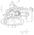
図1に示すように、部品供給装置10は、4個のピックアップノズル(第1部品吸着部)12を備えている。各ピックアップノズル12には、電子部品(部品)Dが吸着される部品吸着面14がそれぞれ形成されている。各ピックアップノズル12は、ぞれぞれの部品吸着面14が径方向外側を向くように回転軸16の円盤部18に取り付けられている。また、各ピックアップノズル12は、相互に等間隔になるように配置されている。このため、隣接するピックアップノズル12同士の開き角度が90度になっている。また、回転軸16は、回転支持部材(回転支持部)20によりベアリング等を介して回転可能に支持されている。これにより、回転軸16が回転することにより、各ピックアップノズル12が回転軸16の軸回りに回転する。また、回転軸16の外周面には、後述のタイミングベルト(回転駆動部)24が掛けられる回転軸プーリ(図示省略)が設けられている。
As shown in FIG. 1, the
また、ピックアップノズル12の部品吸着面14には吸引孔が形成されており、図示しないポンプなどにより空気吸引することにより、部品吸着面14に電子部品Dが吸着できるように構成されている。なお、ポンプの駆動は、後述のコントローラ40(制御部、図2参照)により制御される。
In addition, a suction hole is formed in the
回転支持部材20は、固定部材(固定部)22に上下方向(図1中矢印Z方向)に沿って移動可能となるように取り付けられている。すなわち、固定部材22には上下方向に延びるレール部26が形成されており、回転支持部材20にはこのレール部26に係合してレール部26の延びる方向に沿って移動するガイド部28が形成されている。そして、回転支持部材20は、ガイド部28がレール部26に沿って移動することにより、上下方向に沿って移動することができるようになっている。なお、固定部材22が部品供給装置10の任意の部位に固定されているため、回転支持部材20は、固定部材22に対して移動(相対移動)することになる。また、回転支持部材20のガイド部28の端面には、後述のピニオンギア(直線駆動部、直線駆動機構)34と噛み合うラック部(直線駆動部、直線駆動機構)30が形成されている。
The
固定部材22には、第1サーボモータ(第1駆動源)32が取り付けられている。この第1サーボモータ32の回転軸には、ピニオンギア34が取り付けられている。このピニオンギア34は、ラック部30と噛み合っており、第1サーボモータ32の回転駆動力がピニオンギア34を介して回転支持部材20に伝達される。これにより、第1サーボモータ32が回転駆動することにより、回転支持部材20が上下方向に沿って移動可能になる。このように、部品供給装置は、第1サーボモータ32の回転駆動力を直線運動に変換する直線駆動機構を備えている。なお、この第1サーボモータ32は、回転支持部材20を上下移動させるための第1駆動源として機能している。
A first servo motor (first drive source) 32 is attached to the fixed
また、固定部材22には、第2サーボモータ(第2駆動源)36が取り付けられている。この第2サーボモータ36の回転軸には、固定側プーリ(回転駆動部)38が取り付けられている。この固定側プーリ38と回転軸プーリの外周面には、タイミングベルト24が掛け渡されている。これにより、第2サーボモータ36の回転駆動力がタイミングベルト24を介して回転軸16に伝達される。このため、第2サーボモータ36が回転駆動することにより、回転軸16及び各ピックアップノズル12が回転する。なお、この第2サーボモータ36は、回転軸16及び各ピックアップノズル12を回転させるための第2駆動源として機能している。
Further, a second servo motor (second drive source) 36 is attached to the fixing
ここで、第1サーボモータ32及び第2サーボモータ36は、固定部材22により固定されているため、回転支持部材20の上下移動及び各ピックアップノズル12の回転移動に伴い、移動するものではない。すなわち、各ピックアップノズル12及び回転支持部材20と共に移動する機構に、第1サーボモータ32及び第2サーボモータ36が含まれないため、各ピックアップノズル12及び回転支持部材20と共に移動する機構を軽量化することができる。
Here, since the
図2に示すように、第1サーボモータ32及び第2サーボモータ36の駆動制御は、コントローラ40により実行される。
As shown in FIG. 2, the drive control of the
図1に示すように、部品供給装置10は、単一の実装ヘッド(第2部品吸着部)42を備えている。この実装ヘッド42は、各ピックアップノズル12に吸着された電子部品Dを吸着し、その電子部品Dを回路基板H(図3参照)に実装するものである。また、実装ヘッド42は、円筒状の吸着ノズル部44と、吸着ノズル部44が伸縮可能となるように収容したヘッド本体部46と、を備えている。そして、実装ヘッド42は、ヘッド駆動機構48により、上下方向及び水平方向に沿って移動可能となるように構成されている。ここで、ヘッド駆動機構48は、サーボモータ、ボールネジにより上下方向及び水平方向に沿った直線駆動が可能なアクチュエータで構成されている。また、ヘッド駆動機構48は、コントローラ40により駆動制御されており、実装ヘッド42の移動は、コントローラ40により駆動制御されたヘッド駆動機構48により実現される。
As shown in FIG. 1, the
また、実装ヘッド42には、電子部品Dが吸着される部品吸着面50が形成され、実装ヘッド42の部品吸着面50には吸引孔が形成されており、図示しないポンプなどにより空気吸引することにより、部品吸着面50に電子部品Dが吸着できるように構成されている。なお、ポンプの駆動は、コントローラ40により制御される。
Further, the mounting
また、実装ヘッド42は、吸着ノズル部44が伸縮せずに、そのままヘッド本体部46に固定されている構成でもよい。この場合、実装ヘッド42の上下方向の移動は、吸着ノズル部44がヘッド本体部46と共に上下方向に移動することにより実現される。さらに実装ヘッド42の構造としては、単一以外に直線上、または円周上(ロータリ)に多連配置されたものであってもよい。なお、図9に示すように、ヘッド本体部46の円周上(ロータリ)に多連配置(図9では4個)された実装ヘッド42の場合のヘッド駆動機構48は、サーボモータ、ボールネジにより上下方向及び水平方向に沿った曲線駆動が可能なアクチュエータで構成されている。
Further, the mounting
円盤部18の回転中心の近傍であって後述のXYステージ(部品供給部)56の上方には、プリズム(部品位置認識部)52が配置されている。また、プリズム52の水平方向上の位置には、画像処理装置として機能するカメラ(部品位置認識部)54が配置されている。プリズム52及びカメラ54は、各ピックアップノズル12及び回転軸16と切り離されて設けられている。電子部品Dの位置及び姿勢は、プリズム52を通してカメラ54で認識される。なお、プリズム52及びカメラ54は、回転軸16が回転しても、各ピックアップノズル12及び回転軸16の回転動作と干渉しない位置に設けられている。また、カメラ54により認識された部品の位置及び姿勢は、電子部品Dの位置データとして、コントローラ40に送信される。
A prism (component position recognition unit) 52 is disposed in the vicinity of the rotation center of the
また、部品供給装置10は、複数の電子部品Dが載せられるXYステージ56を備えている。XYステージ56は、サーボモータ及びボールネジで構成されるステージ駆動機構58により、X方向(図1参照)及びY方向(図1参照)に移動可能に構成されている。なお、XYステージ56の上面には、半導体ウエーハなどの電子部品の他に、部品トレーが載せられる。XYステージ56に部品トレーが載せられる場合には、クランプにより固定できる構成になっている。また、ステージ駆動機構58の駆動制御は、コントローラ40により実行される。
Further, the
次に、第1実施形態の部品供給装置10の作用及び効果について説明する。
Next, the operation and effect of the
図1に示すように、カメラ54によりXYステージ56上の電子部品Dの位置及び姿勢が認識され、カメラ54から位置データがコントローラ40に送信される。コントローラ40で位置データが受信されると、電子部品Dがピックアップノズル12の真下に位置するように、コントローラ40によりXYステージ56が移動される。このようにして、XYステージ56上の電子部品Dは、ピックアップノズル12による吸着に最適な位置にくるように調整される。なお、上記した電子部品Dの位置及び姿勢は、隣接するピックアップノズル12同士の間から電子部品Dを認識するようにして実行される。
As shown in FIG. 1, the
次に、電子部品Dがピックアップノズル12の真下に位置すれば、電子部品Dの真上に位置するピックアップノズル12の部品吸着面14が電子部品Dの上面に対して平行になるように、回転軸16の位置制御が実行される。具体的には、回転軸16の位置制御は、第2サーボモータ36が駆動して固定側プーリ38及びタイミングベルト24が回転し、この回転力が回転軸プーリに伝達されることにより、実行される。
Next, if the electronic component D is positioned directly below the
次に、回転軸16の位置制御が実行されて、電子部品Dの真上に位置するピックアップノズル12の部品吸着面14が電子部品Dの上面に対して平行になれば、第1サーボモータ32がコントローラ40により制御されて駆動する。第1サーボモータ32を駆動すると、ピニオンギア34が回転してラック部30に第1サーボモータ32の回転駆動力が伝達される。これにより、ピックアップノズル12は、回転支持部材20と共に、下方向に移動する。このとき、電子部品Dの真上に位置するピックアップノズル12は、その部品吸着面14が電子部品Dの上面に対して平行となる状態で下方向に移動する。
Next, when the position control of the
次に、ピックアップノズル12の部品吸着面14に電子部品Dが接触すると、空気吸引力(真空吸引)により、電子部品Dが部品吸着面14に吸引されてピックアップノズル12に保持される。そして、第2サーボモータ36がコントローラ40により駆動されて、固定側プーリ38が回転する。固定側プーリ38が回転すると、タイミングベルト24を介して、回転軸16が回転し、部品の吸着されていないピックアップノズル12の部品吸着面14に上記の操作により順次電子部品Dが吸着される。このようにして、全てのピックアップノズル12の部品吸着面14に電子部品Dが吸着される。
Next, when the electronic component D comes into contact with the
次に、全てのピックアップノズル12の部品吸着面14に電子部品Dが吸着されると、第1サーボモータ32が逆方向に回転して、回転支持部材20が上方に向かって移動して元の高さに戻る。
Next, when the electronic component D is attracted to the
次に、ピックアップノズル12と実装ヘッド42とが同軸上に位置するように、回転軸16及び円盤部18が回転する。換言すれば、ピックアップノズル12に吸着された電子部品Dの下面と実装ヘッド42の部品吸着面50が平行となるように、回転軸16が第2サーボモータ36により回転制御される。ピックアップノズル12及び回転軸16の回転により、ピックアップノズル12に吸着された電子部品Dの姿勢が順次変更されていく。
Next, the
次に、ピックアップノズル12に吸着された電子部品Dの下面と実装ヘッド42の部品吸着面50が平行となった状態(電子部品Dが反転した状態)で、回転支持部材20が第1サーボモータ32の駆動により上方に移動するとともに、吸着ノズル部44がヘッド本体部46に対して下方向に移動する。なお、吸着ノズル部44がヘッド本体部46に対して伸縮しない構成であれば、吸着ノズル部44がヘッド本体部46とともに下方向に移動する。
Next, in a state where the lower surface of the electronic component D sucked by the
ここで、図4に示すように、ピックアップノズル12が電子部品Dを吸着した位置からピックアップノズル12を左回り(図4中矢印S方向)に90度(右回り(図4中矢印S方向と反対方向)に270度)回転させた状態で、電子部品Dが吸着ノズル部44に吸着されるように構成してもよい。この構成によれば、電子部品Dの側面を吸着ノズル部44に吸着させることができる。このように、電子部品Dの姿勢を自由に変更し、吸着ノズル部44に吸着された電子部品Dの用途によって、電子部品Dの吸着部位を変更することができる。
Here, as shown in FIG. 4, the
ピックアップノズル12に吸着された電子部品Dの下面と吸着ノズル部44の部品吸着面50とが接触し、空気吸引力(真空吸引力)により、電子部品Dが吸着ノズル部44の部品吸着面50に吸着されて実装ヘッド42に保持される。そして、吸着ノズル部44がヘッド本体部46に対して上方向に移動する。なお、吸着ノズル部44がヘッド本体部46に対して伸縮しない構成であれば、吸着ノズル部44がヘッド本体部46とともに上方向に移動する。
The lower surface of the electronic component D sucked by the
次に、図3に示すように、実装ヘッド42がヘッド駆動機構48により移動され、電子部品Dが回路基板Hなどの上面に実装される。
Next, as shown in FIG. 3, the mounting
以上のように、第1実施形態の部品供給装置10によれば、第1サーボモータ32及び第2サーボモータ36が固定部材22に固定されているため、ピックアップノズル12及び回転支持部材20の重量を軽量化することができる。これにより、ピックアップノズル12及び回転支持部材20を移動させるときの動力が小さくてすみ、各サーボモータ32、36は小出力の小型のもので足りる。また、各サーボモータ32、36を小型化することにより、部品供給装置10全体を小型化することができる。また、各サーボモータ32、36を小型化することにより、駆動時に不要な振動の発生を低減することができるため、電子部品Dを実装したときの電子部品Dの実装精度を向上させることができる。
As described above, according to the
また、ピックアップノズル12及び回転支持部材20の重量を軽量化することにより、ピックアップノズル12及び回転支持部材20に発生する慣性力が小さくなる。これにより、小型のサーボモータにより、ピックアップノズル12及び回転支持部材20を高速でかつ高精度に移動させることができる。この結果、ピックアップノズル12及び回転支持部材20の位置制御を容易かつ正確に実行することができ、電子部品Dの実装精度を高めることができる。
Further, by reducing the weight of the
また、ピックアップノズル12及び回転支持部材20の位置精度を高めることにより、ピックアップノズル12に電子部品Dを吸着するときの電子部品Dに作用する荷重(衝撃力)が小さくなる。これにより、電子部品Dに割れなどが発生することを防止できる。特に、電子部品Dが材料強度の低い材料で構成され、あるいは部品が薄型のもので、電子部品D自体の強度が低い場合でも、電子部品Dが破損することを防止できる。
Further, by increasing the positional accuracy of the
ここで、ピックアップノズル12による電子部品Dの吸着時には、第1サーボモータ32の回転駆動力がピニオンギア34及びラック部30を介して回転支持部材20に伝達される。回転支持部材に第1サーボモータ32の回転駆動力が伝達されると、ピックアップノズル12及び回転支持部材20が上下方向に移動する。このように、第1サーボモータ32の回転駆動力が直線駆動機構により直線運動に変換されてピックアップノズル12及び回転支持部材20が上下方向に移動する。このため、ピックアップノズル12は、電子部品Dの上面に対して垂直方向から電子部品Dに接触することになる。これにより、ピックアップノズル12が電子部品Dに接触するときに、ピックアップノズル12が電子部品Dに対して水平方向に位置ずれすることを防止できる。また、ピックアップノズル12の電子部品Dに対する位置ずれを防止することにより、実装ヘッド42の吸着ノズル部44の電子部品Dに対する位置ずれも防止できる。この結果、下流の実装工程において、電子部品Dの実装精度を高めることができる。
Here, when the electronic component D is attracted by the
また、XYテーブル56に支持された電子部品Dの位置がプリズム52及びカメラ54により認識され、この認識結果に基づいてXYテーブル56に支持された電子部品Dの位置がピックアップ作業に最適な位置となるように補正される。このように、ピックアップノズル12に吸着される前の段階で、電子部品Dが最適な部位に位置するように位置制御することにより、ピックアップノズル12に対する電子部品Dの位置精度を高めることができるとともに、ピックアップノズル12及び回転支持部材20を下方向に移動させるだけで、電子部品Dを吸着することができる。また、ピックアップノズル12が180度(90度、あるいは270度)回転された位置で、実装ヘッド42の吸着ノズル部44を待機させておくことにより、実装ヘッド42の吸着ノズル部44を上下方向に移動するだけで、ピックアップノズル12に吸着された電子部品Dを吸着ノズル部44に吸着させることができる。これにより、ピックアップノズル12及び吸着ノズル部44により電子部品Dを吸着するときのピックアップノズル12及び吸着ノズル部44の移動距離を最短距離にすることができる。この結果、電子部品Dの吸着処理に必要な時間を短縮することができ、電子部品Dの吸着能力及び実装能力を向上させることができる。
Further, the position of the electronic component D supported by the XY table 56 is recognized by the
次に、本発明の第2実施形態に係る部品供給装置について説明する。
なお、第1実施形態に係る部品供給装置の構成と重複する構成については同符号を付し、適宜、その説明を省略する。
Next, a component supply apparatus according to a second embodiment of the present invention will be described.
In addition, about the structure which overlaps with the structure of the component supply apparatus which concerns on 1st Embodiment, the same code | symbol is attached | subjected and the description is abbreviate | omitted suitably.
図5及び図6に示すように、第2実施形態の部品供給装置は、ダイシングシート(図示省略)に置かれている電子部品Dを上方に押し上げる押上ピン(部品押上部)60が設けられている。この押上ピン60は、ピン駆動機構62により上下方向に沿って移動可能となるように構成されている。このピン駆動機構62は、コントローラ40により駆動制御される。具体的には、ピン駆動機構62は、サーボモータ及びカムなどにより上下移動を可能にするものであり、ダイシングシートを吸着固定する吸引ポッド部(図示省略)を備えている。
As shown in FIGS. 5 and 6, the component supply apparatus of the second embodiment is provided with a push-up pin (component push-up portion) 60 that pushes up the electronic component D placed on a dicing sheet (not shown). Yes. This push-up
ここで、コントローラ40は、押上ピン60により電子部品Dが押し上げられてピックアップノズル12に吸着されるピックアップ吸着処理(第1吸着工程)と、他のピックアップノズル12に吸着されている電子部品Dが実装ヘッド42の吸着ノズル部44に吸着される受け渡し吸着処理(第2吸着工程)と、が同時に実行されるように、押上ピン60の上下移動、ピックアップノズル12(回転支持部材20)の上下移動、及び吸着ノズル部44(実装ヘッド42)の上下移動が同期して制御される。詳細には、押上ピン60、ピックアップノズル12(回転支持部材20)及び吸着ノズル部44(実装ヘッド42)の動作ファイルは、コントローラ40により演算処理され、相対的な動作プロファイルがそれぞれ最適となるように制御される。なお、押上ピン42、ピックアップノズル12(回転支持部材20)、及び吸着ノズル部44の駆動方法は、上述した通りである。
Here, the
具体的には、図5(A)は、押上ピン60の上方に位置する電子部品Dの上面に任意のピックアップノズル12の部品吸着面14が接触し、さらに、このピックアップノズル12に対して180度反対側の位置にある他のピックアップノズル12の部品吸着面14に吸着されている電子部品Dの下面に実装ヘッド42の吸着ノズル部44の部品吸着面50が接触した状態となっている。
Specifically, in FIG. 5A, the
そして、図5(B)に示すように、押上ピン60が上方向に移動し、電子部品Dをダイシングシートから上方に向けて押し上げると同時に、各ピックアップノズル12及び回転支持部材20が上方向に移動する。このとき、押し上げられる電子部品Dと対向するピックアップノズル12の部品吸着面14に、押し上げられた電子部品Dの上面が吸着されると同時に、実装ヘッド42の吸着ノズル部44に他のピックアップノズル12に吸着されている他の電子部品Dが吸着される。その後、他の電子部品Dが吸着された状態で、実装ヘッド42の吸着ノズル部44は、上方向に移動する。
Then, as shown in FIG. 5B, the push-up
第2実施形態によれば、押上ピン60の上方への移動、各ピックアップノズル12及び回転支持部材20の上方向への移動、及び実装ヘッド42の吸着ノズル部44の上方向への移動がコントローラ40により同期して制御され、押上ピン60により電子部品Dが押し上げられて任意のピックアップノズル12に吸着される第1吸着工程と、他のピックアップノズル12に吸着されている電子部品Dが実装ヘッド42の吸着ノズル部44に吸着される第2吸着工程と、が同時に実行される。これにより、第1吸着工程と第2吸着工程を異なるタイミングで別々に実行する場合と比較して、実装ヘッド42の吸着ノズル部44に電子部品Dを吸着させるまでの時間を短縮することができる。この結果、電子部品Dの供給能力が向上し、下流の実装工程において、電子部品Dを効率良く実装することができる。
According to the second embodiment, the upward movement of the push-up
また、実装ヘッド42の吸着ノズル部44に電子部品Dを吸着させるまでの時間を短縮することにより、この短縮した時間を他の処理を実行する時間にまわすことができる。特に、ピックアップノズル12で電子部品Dを吸着するときに、ピックアップノズル12の電子部品Dに対する下方向に向かう移動の移動速度を低下することにより、ピックアップノズル12で電子部品Dを吸着するときに電子部品Dに及ぼす荷重(衝撃力)を低減することができる。この結果、電子部品Dに傷などがついてしまうことを防止でき、電子部品Dの品質を向上させることができる。
Further, by shortening the time until the electronic component D is attracted to the
特に、図9及び図10に示すように、多連(例えば、4個)の吸着ノズル部44を備えた実装ヘッド42の場合は、複数のピックアップノズル12から各吸着ノズル部44に電子部品Dが次々に受け渡され、電子部品Dを受け渡された吸着ノズル部44が移動して実装工程を行なっている間に、それと同期して、電子部品Dを受け渡して未吸着となったピックアップノズル12に次の電子部品Dを吸着させることが可能になる。これにより、吸着ノズル部44による電子部品Dの実装処理と同時にピックアップノズル12による次の電子部品Dのピックアップ処理が可能になる。そして、次の電子部品Dを吸着したピックアップノズル12から未吸着の吸着ノズル部44に電子部品Dが受け渡され、電子部品Dを受け渡された上記吸着ノズル部44による実装処理と同時に未吸着となったピックアップノズル12による次の電子部品Dのピックアップ処理が可能になる。これを繰り返すことにより、ピックアップノズル12による電子部品Dのピックアップ処理、ピックアップノズル12から吸着ノズル部44への電子部品Dの受渡し処理、吸着ノズル部44による電子部品Dの実装処理の3つの処理工程を短時間でかつ円滑に実行することができる。
In particular, as shown in FIGS. 9 and 10, in the case of a mounting
次に、本発明の第3実施形態に係る部品供給装置について説明する。
なお、第1実施形態に係る部品供給装置の構成と重複する構成については同符号を付し、適宜、その説明を省略する。
Next, a component supply apparatus according to a third embodiment of the present invention will be described.
In addition, about the structure which overlaps with the structure of the component supply apparatus which concerns on 1st Embodiment, the same code | symbol is attached | subjected and the description is abbreviate | omitted suitably.
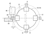
図7及び図8に示すように、第3実施形態の部品供給装置は、XYテーブル56上の電子部品Dの上面とピックアップノズル12の部品吸着面14とが平行に対面する状態から、ピックアップノズル12を右回りに270度(左回りに90度)回転させた位置に設けられた受け渡しステージ(部品支持部)64を備えている。
As shown in FIGS. 7 and 8, the component supply apparatus according to the third embodiment starts from the state where the upper surface of the electronic component D on the XY table 56 and the
なお、受け渡しステージ64は、各ピックアップノズル12の回転軌跡上から退避した位置、換言すれば、各ピックアップノズル12が回転したときに各ピックアップノズル12に接触しない位置に設けられている。また、受け渡しステージ64のピックアップノズル12と対面する端面とピックアップノズル12との間には、所定のクリアランスCが設けられている。また、ピックアップノズル12(回転支持部材20)、及び吸着ノズル部44の駆動方法は、上述した通りである。
The
第3実施形態によれば、XYテーブル56に支持された電子部品Dがピックアップノズル12により吸着され、XYテーブル56上の電子部品Dの上面とピックアップノズル12の部品吸着面14とが平行に対面する状態からピックアップノズル12が右回りに270度だけ回転する。これにより、電子部品Dは受け渡しステージ64の上面上に位置し、電子部品Dの側面が上方を向いた状態(姿勢)になる。
According to the third embodiment, the electronic component D supported by the XY table 56 is sucked by the
次に、実装ヘッド42がヘッド駆動機構48により駆動されて、吸着ノズル部44の部品吸着面50に電子部品Dの側面が吸着される。このとき、電子部品Dの側面には、実装ヘッド42の吸着ノズル部44から所定の荷重(衝撃力)が作用するが、電子部品Dの反対側の側面が受け渡しステージ64で支持されるため、電子部品Dが実装ヘッド42と受け渡しステージ64で上下方向から強固に挟まれる形になる。これにより、実装ヘッド42の吸着ノズル部44から電子部品Dに対して所定の荷重(衝撃力)が作用した場合でも、電子部品Dが位置ずれすることを防止できる。なお、吸着ノズル部44の部品吸着面50に電子部品Dの側面が吸着されると、実装ヘッド42がヘッド駆動機構48により駆動され、下流の実装工程が実行される。
Next, the mounting
以上のように、各ピックアップノズル12に吸着された電子部品Dを180度回転(反転)させた状態で実装ヘッド42の吸着ノズル部44に吸着させることに加え、各ピックアップノズル12に吸着された電子部品Dを270度回転させた状態で、実装ヘッド42の吸着ノズル部44に吸着させることも可能になる。これにより、実装ヘッド42の吸着ノズル部44に電子部品Dが吸着された後の処理の内容によって、他の機構を設けることなく、電子部品Dの姿勢を適宜変更することができる。この結果、部品供給装置の部品点数を削減して大型化を防止でき、製造コストが増加することも防止できる。また、部品供給装置の部品点数を削減することにより、各処理工程も削減でき、部品の供給能力及び供給効率を高めることができる。
As described above, the electronic component D sucked by each
特に、実装ヘッド42の吸着ノズル部44による電子部品Dの吸着時には、電子部品Dが受け渡しステージ64により下方から支持されるため、実装ヘッド42の吸着ノズル部44から作用する荷重により電子部品Dが位置ずれすることを防止できる。これにより、電子部品Dが位置ずれすることなく、実装ヘッド42の吸着ノズル部44に吸着されるため、下流の実装工程における電子部品Dの実装精度を高めることができる。また、実装ヘッド42の吸着ノズル部44により電子部品Dを吸着する際に、何らかの不都合により、電子部品Dが吸着ノズル部44から離脱した場合でも、電子部品Dは、受け渡しステージ64に支持される。このため、電子部品Dが下方向に大きく落下して破損することを防止できる。
In particular, when the electronic component D is attracted by the
また、受け渡しステージ64が各ピックアップノズル12の回転軌跡上から退避した位置に設けられているため、各ピックアップノズル12が回転するときに受け渡しステージ64が干渉することがない。これにより、ピックアップノズル12が回転したときに各ピックアップノズル12と受け渡しステージ64が接触することがないように、各ピックアップノズル12又は受け渡しステージ64の一方を逃がす工程が不要になる。この結果、工程数の増加に伴う作業時間を省くことができるため、電子部品Dの供給能力を向上させることができる。
Further, since the
なお、第3実施形態は、受け渡しステージ64を、XYテーブル56上の電子部品Dの上面とピックアップノズル12の部品吸着面14とが平行に対面する状態から、ピックアップノズル12を右回りに270度(左回りに90度)回転させた位置に設けられた構成を示したが、この位置に限られず、例えば、受け渡しステージ64を、XYテーブル56上の電子部品Dの上面とピックアップノズル12の部品吸着面14とが平行に対面する状態から、ピックアップノズル12を右回りに90度(左回りに270度)回転させた位置に設けるようにしてもよい。受け渡しステージ64の位置は、特に限定されるものではなく、電子部品Dの姿勢との関係で適宜調整することができる。
In the third embodiment, the
10 部品供給装置
12 ピックアップノズル(第1部品吸着部)
20 回転支持部材(回転支持部)
22 固定部材(固定部)
24 タイミングベルト(回転駆動部)
30 ラック部(直線駆動部、直線駆動機構)
32 第1サーボモータ(第1駆動源)
34 ピニオンギア(直線駆動部、直線駆動機構)
36 第2サーボモータ(第2駆動源)
38 固定側プーリ(回転駆動部)
40 コントローラ(制御部)
42 実装ヘッド(第2部品吸着部)
52 プリズム(部品位置認識部)
54 カメラ(部品位置認識部)
56 XYテーブル(部品供給部)
60 押上ピン(部品押上部)
64 受け渡しステージ(部品支持部)
D 電子部品(部品)
10
20 Rotation support member (Rotation support part)
22 Fixing member (fixing part)
24 Timing belt (rotary drive)
30 rack part (linear drive part, linear drive mechanism)
32 1st servo motor (1st drive source)
34 Pinion gear (linear drive unit, linear drive mechanism)
36 Second servo motor (second drive source)
38 Fixed pulley (rotary drive)
40 Controller (control unit)
42 Mounting head (second component suction part)
52 Prism (component position recognition unit)
54 Camera (part position recognition unit)
56 XY table (component supply unit)
60 Push-up pin (part push-up)
64 Delivery stage (part support part)
D Electronic parts (parts)
Claims (6)
前記第1部品吸着部を回転可能に支持する回転支持部と、
前記第1部品吸着部及び前記回転支持部を直線方向に沿って移動させる直線駆動部と、
前記第1部品吸着部を前記回転支持部の軸回りに回転させて前記第1部品吸着部に吸着された前記部品の姿勢を変更する回転駆動部と、
前記回転支持部を前記直線方向に沿って移動可能となるように支持する固定部と、
前記固定部に設けられ前記直線駆動部を駆動する第1駆動源と、
前記固定部に設けられ前記回転駆動部を駆動する第2駆動源と、
前記回転駆動部により姿勢が変更された前記部品を吸着する第2部品吸着部と、
を有する部品供給装置であって、
前記第1部品吸着部は、複数設けられ、
前記第2部品吸着部は、一つまたは複数設けられ、かつ前記直線方向に沿って移動可能に設けられ、
前記第1部品吸着部に吸着される前記部品を前記第1部品吸着部側に押し出す部品押出部は、前記直線方向に沿って移動可能に設けられ、
前記部品押出部の直線移動、前記第1部品吸着部の直線移動及び前記第2部品吸着部の直線移動を同期させる制御部と、を有し、
前記部品押出部の直線移動、前記第1部品吸着部の直線移動及び前記第2部品吸着部の直線移動が前記制御部により同期されて、前記部品押出部により前記部品が押し出されて一方の前記第1部品吸着部に吸着される第1吸着工程と、他方の前記第1部品吸着部に吸着されている前記部品が前記第2部品吸着部に吸着される第2吸着工程と、が同時に実行されることを特徴とする部品供給装置。 A first component suction portion for sucking components;
A rotation support portion for rotatably supporting the first component suction portion;
A linear drive unit that moves the first component suction unit and the rotation support unit along a linear direction;
A rotation drive unit configured to rotate the first component adsorption unit around an axis of the rotation support unit to change the posture of the component adsorbed by the first component adsorption unit;
A fixing portion that supports the rotation support portion so as to be movable along the linear direction;
A first drive source provided in the fixed portion and driving the linear drive portion;
A second drive source that is provided in the fixed part and drives the rotation drive part;
A second component suction unit that sucks the component whose posture has been changed by the rotation drive unit;
A component supply device comprising:
A plurality of the first component suction portions are provided,
One or a plurality of the second component suction portions are provided, and provided so as to be movable along the linear direction,
The component push-out unit that pushes out the component sucked by the first component suction unit to the first component suction unit side is provided movably along the linear direction,
A controller that synchronizes the linear movement of the component extruding unit, the linear movement of the first component adsorbing unit, and the linear movement of the second component adsorbing unit, and
The linear movement of the component extruding part, the linear movement of the first part adsorbing part, and the linear movement of the second component adsorbing part are synchronized by the control part, and the part is pushed out by the part extruding part and The first suction step to be sucked by the first component suction portion and the second suction step to suck the component sucked by the other first component suction portion to the second component suction portion are executed simultaneously. A component supply device characterized by being made.
前記第1駆動源からの駆動力が前記直線駆動機構により直線運動に変換されて前記第1部品吸着部及び前記回転支持部が直線方向に移動することを特徴とする請求項1に記載の部品供給装置。 The linear drive unit is a linear drive mechanism that converts the drive force of the first drive source into a linear motion,
2. The component according to claim 1, wherein a driving force from the first driving source is converted into a linear motion by the linear driving mechanism, and the first component suction unit and the rotation support unit move in a linear direction. Feeding device.
前記部品供給部に支持された前記部品の位置を認識する部品位置認識部と、
を有し、
前記部品位置認識部により認識された結果に基づいて前記部品供給部に支持された前記部品の位置が補正されることを特徴とする請求項1に記載の部品供給装置。 A component supply unit for supporting the component sucked by the first component suction unit;
A component position recognition unit for recognizing the position of the component supported by the component supply unit;
Have
The component supply apparatus according to claim 1, wherein the position of the component supported by the component supply unit is corrected based on a result recognized by the component position recognition unit.
Priority Applications (1)
| Application Number | Priority Date | Filing Date | Title |
|---|---|---|---|
| JP2012137060A JP2012186505A (en) | 2012-06-18 | 2012-06-18 | Component supply device |
Applications Claiming Priority (1)
| Application Number | Priority Date | Filing Date | Title |
|---|---|---|---|
| JP2012137060A JP2012186505A (en) | 2012-06-18 | 2012-06-18 | Component supply device |
Related Parent Applications (1)
| Application Number | Title | Priority Date | Filing Date |
|---|---|---|---|
| JP2008097159A Division JP2009252890A (en) | 2008-04-03 | 2008-04-03 | Component supply device |
Publications (1)
| Publication Number | Publication Date |
|---|---|
| JP2012186505A true JP2012186505A (en) | 2012-09-27 |
Family
ID=47016217
Family Applications (1)
| Application Number | Title | Priority Date | Filing Date |
|---|---|---|---|
| JP2012137060A Pending JP2012186505A (en) | 2012-06-18 | 2012-06-18 | Component supply device |
Country Status (1)
| Country | Link |
|---|---|
| JP (1) | JP2012186505A (en) |
Cited By (5)
| Publication number | Priority date | Publication date | Assignee | Title |
|---|---|---|---|---|
| JP2018533842A (en) * | 2015-10-16 | 2018-11-15 | ミュールバウアー ゲゼルシャフト ミット ベシュレンクテル ハフツング ウント コンパニー コマンディトゲゼルシャフト | Component receiving device |
| KR20180134934A (en) * | 2016-04-27 | 2018-12-19 | 엠아이티 세미콘덕터 피티이 엘티디 | Transport system for flipping and multiplexing electronic devices |
| JP2019505453A (en) * | 2015-10-16 | 2019-02-28 | ミュールバウアー ゲゼルシャフト ミット ベシュレンクテル ハフツング ウント コンパニー コマンディトゲゼルシャフト | Component operation device |
| CN109699167A (en) * | 2017-10-20 | 2019-04-30 | 先进装配系统有限责任两合公司 | Complementary tool for a chip transfer device with a removal tool and a turning tool |
| JP2020183907A (en) * | 2019-05-08 | 2020-11-12 | アスリートFa株式会社 | Electronic component inspection device |
Citations (6)
| Publication number | Priority date | Publication date | Assignee | Title |
|---|---|---|---|---|
| JPS6226833A (en) * | 1985-07-26 | 1987-02-04 | Mitsubishi Electric Corp | Die bonding device |
| JPH11102936A (en) * | 1997-07-28 | 1999-04-13 | Matsushita Electric Ind Co Ltd | Method and equipment for supplying part |
| JP2001320195A (en) * | 2000-05-09 | 2001-11-16 | Yamaha Motor Co Ltd | Composite mounting device |
| JP2006093321A (en) * | 2004-09-22 | 2006-04-06 | Matsushita Electric Ind Co Ltd | Component mounting apparatus and component mounting method |
| JP2006108193A (en) * | 2004-10-01 | 2006-04-20 | Tokyo Weld Co Ltd | Pickup device and pickup method |
| JP2007234681A (en) * | 2006-02-27 | 2007-09-13 | Apic Yamada Corp | Semiconductor manufacturing apparatus |
-
2012
- 2012-06-18 JP JP2012137060A patent/JP2012186505A/en active Pending
Patent Citations (6)
| Publication number | Priority date | Publication date | Assignee | Title |
|---|---|---|---|---|
| JPS6226833A (en) * | 1985-07-26 | 1987-02-04 | Mitsubishi Electric Corp | Die bonding device |
| JPH11102936A (en) * | 1997-07-28 | 1999-04-13 | Matsushita Electric Ind Co Ltd | Method and equipment for supplying part |
| JP2001320195A (en) * | 2000-05-09 | 2001-11-16 | Yamaha Motor Co Ltd | Composite mounting device |
| JP2006093321A (en) * | 2004-09-22 | 2006-04-06 | Matsushita Electric Ind Co Ltd | Component mounting apparatus and component mounting method |
| JP2006108193A (en) * | 2004-10-01 | 2006-04-20 | Tokyo Weld Co Ltd | Pickup device and pickup method |
| JP2007234681A (en) * | 2006-02-27 | 2007-09-13 | Apic Yamada Corp | Semiconductor manufacturing apparatus |
Cited By (10)
| Publication number | Priority date | Publication date | Assignee | Title |
|---|---|---|---|---|
| JP2018533842A (en) * | 2015-10-16 | 2018-11-15 | ミュールバウアー ゲゼルシャフト ミット ベシュレンクテル ハフツング ウント コンパニー コマンディトゲゼルシャフト | Component receiving device |
| JP2019505453A (en) * | 2015-10-16 | 2019-02-28 | ミュールバウアー ゲゼルシャフト ミット ベシュレンクテル ハフツング ウント コンパニー コマンディトゲゼルシャフト | Component operation device |
| EP3576138A1 (en) * | 2015-10-16 | 2019-12-04 | Mühlbauer GmbH & Co. KG. | Component handling device |
| KR20180134934A (en) * | 2016-04-27 | 2018-12-19 | 엠아이티 세미콘덕터 피티이 엘티디 | Transport system for flipping and multiplexing electronic devices |
| KR102276620B1 (en) * | 2016-04-27 | 2021-07-13 | 엠아이티 세미콘덕터 피티이 엘티디 | Transport system for flipping and multi-inspecting electronic devices |
| CN109699167A (en) * | 2017-10-20 | 2019-04-30 | 先进装配系统有限责任两合公司 | Complementary tool for a chip transfer device with a removal tool and a turning tool |
| JP2019080061A (en) * | 2017-10-20 | 2019-05-23 | エーエスエム・アセンブリー・システムズ・ゲーエムベーハー・ウント・コ・カーゲー | Supplementary tool for chip transfer device with removal tool and turning tool |
| CN109699167B (en) * | 2017-10-20 | 2020-11-06 | 先进装配系统有限责任两合公司 | Complementary tool for a chip transfer device with a removal tool and a turning tool |
| US11088013B2 (en) | 2017-10-20 | 2021-08-10 | Asm Assembly Systems Gmbh & Co. Kg | Supplementary tool for chip transfer device with removal tool and turning tool |
| JP2020183907A (en) * | 2019-05-08 | 2020-11-12 | アスリートFa株式会社 | Electronic component inspection device |
Similar Documents
| Publication | Publication Date | Title |
|---|---|---|
| JP5989313B2 (en) | Die bonder and bonding method | |
| JP4390503B2 (en) | Component mounting apparatus and component mounting method | |
| JP6513226B2 (en) | Electronic parts handling unit | |
| JP4308772B2 (en) | Component supply head device, component supply device, component mounting device, and mounting head unit moving method | |
| TW201735203A (en) | Electronic component mounting apparatus | |
| JP2012186505A (en) | Component supply device | |
| JP5507775B1 (en) | Bonding apparatus and bonding method | |
| JP2012023230A (en) | Mounting machine | |
| KR101893213B1 (en) | Electronic component mounting apparatus, and electronic component mounting method | |
| JP2009252890A (en) | Component supply device | |
| JPH11102936A (en) | Method and equipment for supplying part | |
| JP5781642B2 (en) | Bonding equipment | |
| JP2017059777A (en) | Conveyance device and solder ball print system | |
| JP5850794B2 (en) | Component conveying device and component mounting machine | |
| JP2008036785A (en) | Assembling device, assembling and manufacturing method, and assembly line | |
| KR20090041308A (en) | Chip transporting method and the device thereof | |
| JP6650253B2 (en) | Electronic component mounting machine | |
| JP4862872B2 (en) | Component mounting equipment | |
| JP4296826B2 (en) | Electronic component mounting apparatus and electronic component mounting method | |
| JP5479961B2 (en) | Electronic component mounting apparatus and mounting method | |
| JP2015220416A (en) | Component mounting system | |
| JP6715591B2 (en) | Electronic component mounting machine | |
| JP4752889B2 (en) | Component mounting equipment | |
| JP2009188028A (en) | Mounting method of electronic component | |
| JP2008277612A (en) | Chip carrying apparatus |
Legal Events
| Date | Code | Title | Description |
|---|---|---|---|
| A621 | Written request for application examination |
Free format text: JAPANESE INTERMEDIATE CODE: A621 Effective date: 20120618 |
|
| A977 | Report on retrieval |
Free format text: JAPANESE INTERMEDIATE CODE: A971007 Effective date: 20130620 |
|
| A131 | Notification of reasons for refusal |
Free format text: JAPANESE INTERMEDIATE CODE: A131 Effective date: 20130624 |
|
| A02 | Decision of refusal |
Free format text: JAPANESE INTERMEDIATE CODE: A02 Effective date: 20131022 |