JP2012182003A - Lighting system - Google Patents

Lighting system Download PDF

Info

Publication number
JP2012182003A
JP2012182003A JP2011043897A JP2011043897A JP2012182003A JP 2012182003 A JP2012182003 A JP 2012182003A JP 2011043897 A JP2011043897 A JP 2011043897A JP 2011043897 A JP2011043897 A JP 2011043897A JP 2012182003 A JP2012182003 A JP 2012182003A
Authority
JP
Japan
Prior art keywords
light
excitation light
light source
excitation
phosphor layer
Prior art date
Legal status (The legal status is an assumption and is not a legal conclusion. Google has not performed a legal analysis and makes no representation as to the accuracy of the status listed.)
Withdrawn
Application number
JP2011043897A
Other languages
Japanese (ja)
Inventor
Takao Saito
貴夫 齋藤
Takashi Sato
孝 佐藤
Current Assignee (The listed assignees may be inaccurate. Google has not performed a legal analysis and makes no representation or warranty as to the accuracy of the list.)
Stanley Electric Co Ltd
Original Assignee
Stanley Electric Co Ltd
Priority date (The priority date is an assumption and is not a legal conclusion. Google has not performed a legal analysis and makes no representation as to the accuracy of the date listed.)
Filing date
Publication date
Application filed by Stanley Electric Co Ltd filed Critical Stanley Electric Co Ltd
Priority to JP2011043897A priority Critical patent/JP2012182003A/en
Publication of JP2012182003A publication Critical patent/JP2012182003A/en
Withdrawn legal-status Critical Current

Links

Images

Abstract

PROBLEM TO BE SOLVED: To provide a lighting system with little maintenance necessity enabling installation at a high ceiling area, and also with reduced cost and with small lightness reduction even when used at a distance.SOLUTION: The lighting system includes: an excitation light source section 11 provided with a solid light source 12 which emits light as excitation light with a predetermined wavelength in a wavelength region from ultraviolet light to visible light; and a passive light-emitting section 21 arranged at a distant location from the excitation light source section 11 and to emit light for illumination based on the excitation light incident from the solid light source 12 of the excitation light source section 11 through aerial transmission. The passive light-emitting section 21 includes: a pillar 22; a phosphor layer 23 provided with at least one kind of phosphor which emits fluorescent light, excited by the excitation light guided in the pillar 22, with a longer wavelength than that of the excitation light; and a light guide member 24 arranged around the phosphor layer 23 for guiding both light emitted by the phosphor layer 23 and the excitation light together.

Description

本発明は、照明装置に関する。   The present invention relates to a lighting device.

近年、LEDの高輝度化に伴って、従来の表示用途から照明用途に加速度的に応用展開が進んでいる。超寿命でメンテナンスフリー性に有利であることから、特にハイパワー品は電球や放電灯の代替として、実用製品が市場に浸透しつつある。   In recent years, with the increase in brightness of LEDs, application development has been accelerated from conventional display applications to illumination applications. Since it has a long life and is advantageous for maintenance-free, high-power products are becoming popular in the market as substitutes for light bulbs and discharge lamps.

LEDやLD(レーザダイオード)などの半導体発光素子は、点光源に近い照射特性を持ち光学設計が容易であることから、スクリーン投影用のプロジェクターや、車両用前照灯等の開発・実用化が進んでいる。   Semiconductor light emitting devices such as LEDs and LDs (laser diodes) have illumination characteristics close to that of point light sources and are easy to design optically. Therefore, the development and commercialization of projectors for screen projection, vehicle headlamps, etc. Progressing.

しかしながら、半導体発光素子は発熱量が多い割には熱に弱いデバイスであり、直流の電流駆動方式であるために点灯回路が別途必要である。このように、光源だけでなく周辺部材に技術コストとメンテナンス性を要するという短所を持っている。   However, the semiconductor light emitting device is a device that is weak against heat even though it generates a large amount of heat, and requires a separate lighting circuit because it is a direct current drive system. In this way, not only the light source but also the peripheral members have the disadvantage of requiring technical cost and maintainability.

放電灯の代替として期待されている応用製品の1つに高所照明がある。高所ではメンテナンスが大変であるため、高所での交換作業を回避するための灯具ユニットに関する提案がなされている。例えば特許文献1には、照明が必要な場所まで光源から導光する構成が示されている。   One of the application products that are expected as an alternative to the discharge lamp is the high place lighting. Since it is difficult to maintain at high places, proposals have been made regarding lamp units to avoid replacement work at high places. For example, Patent Document 1 shows a configuration in which light is guided from a light source to a place where illumination is necessary.

図1は特許文献1の照明装置を示す図である。図1を参照すると、特許文献1の照明装置は、構造物の下部等の安全な場所に設けた光源部101と、構造物の上部に設け、光源部101からの光を所定方向に向けて出射する出光部103と、光源部101から出光部103まで光を伝送する光伝送体102とを備えている。   FIG. 1 is a diagram showing an illumination device of Patent Document 1. In FIG. Referring to FIG. 1, the illumination device of Patent Document 1 is provided with a light source unit 101 provided in a safe place such as a lower part of a structure and an upper part of the structure, and directs light from the light source unit 101 in a predetermined direction. The light output part 103 which radiate | emits, and the optical transmission body 102 which transmits light from the light source part 101 to the light output part 103 are provided.

特許文献1の照明装置によれば、照明装置の出光部分を使用目的に合わせて例えば高所や危険な鉄道用高圧線の近傍等の所望の場所に設置する場合であっても、光源部分のランプ等は安全な場所で交換することができる。   According to the illuminating device of Patent Literature 1, even if the light output portion of the illuminating device is installed in a desired place such as a high place or in the vicinity of a dangerous railway high-voltage line according to the purpose of use, Lamps can be replaced in a safe place.

特開平9−035517号公報Japanese Patent Laid-Open No. 9-035517

しかしながら、特許文献1の照明装置では、光源部101から出光部103まで光を伝送する光伝送体102を用いているので、光源部101から照射場所まで遠距離となる場合に、必要な導光部材のコストが嵩むという問題があった。さらに、特許文献1の照明装置では、光源部101から照射場所まで白色光を導光させるため、距離に比例して明るさが低下してしまうという問題があった。   However, since the illumination device of Patent Document 1 uses the optical transmission body 102 that transmits light from the light source unit 101 to the light output unit 103, a necessary light guide is required when the light source unit 101 is far from the irradiation place. There was a problem that the cost of the member increased. Furthermore, in the illuminating device of patent document 1, since white light was guided from the light source part 101 to the irradiation place, there existed a problem that a brightness fell in proportion to distance.

本発明は、高天井などに対応可能なメンテンスフリー性を有し、さらに、コストを低減するとともに遠距離でも明るさの低下が少ない照明装置を提供することを目的としている。   An object of the present invention is to provide an illuminating device that has a maintenance-free property that can be applied to a high ceiling or the like, further reduces cost, and causes little reduction in brightness even at a long distance.

上記目的を達成するために、請求項1記載の発明は、紫外光から可視光までの波長領域のうちの所定の波長の光を励起光として発光する固体光源を有する励起光源部と、該励起光源部とは空間的に離れた位置に設置され、該励起光源部の前記固体光源から出射された励起光が空中伝送により入射するときに、入射した励起光に基づいて照明光を出射する受動発光部とを備えた照明装置であって、前記受動発光部は、該受動発光部を支えるとともに前記入射した励起光を導光する支柱と、該支柱内を導光した励起光により励起され該励起光の波長よりも長波長の蛍光を発光する少なくとも1種類の蛍光体を含む蛍光体層と、該蛍光体層で発光した蛍光と励起光とをあわせて導光させる導光部材とを有していることを特徴としている。   In order to achieve the above object, an invention according to claim 1 is an excitation light source unit including a solid light source that emits light having a predetermined wavelength in a wavelength region from ultraviolet light to visible light as excitation light, and the excitation A passive light source that is installed at a position spatially separated from the light source unit and emits illumination light based on the incident excitation light when the excitation light emitted from the solid-state light source of the excitation light source unit is incident by air transmission. A light emitting unit, wherein the passive light emitting unit supports the passive light emitting unit and guides the incident excitation light, and is excited by excitation light guided in the support column. A phosphor layer including at least one type of phosphor that emits fluorescence having a wavelength longer than the wavelength of the excitation light; and a light guide member that guides the fluorescence emitted from the phosphor layer together with the excitation light. It is characterized by that.

また、請求項2記載の発明は、請求項1記載の照明装置において、前記受動発光部には、前記励起光源部からの励起光を反射して、前記支柱内に所定の角度で入射させるための反射手段がさらに設けられていることを特徴としている。   According to a second aspect of the present invention, in the illumination device according to the first aspect, the passive light emitting unit reflects the excitation light from the excitation light source unit so as to be incident on the support column at a predetermined angle. The reflection means is further provided.

また、請求項3記載の発明は、請求項1または請求項2に記載の照明装置において、前記励起光源部の前記固体光源には、励起光としてコヒーレント光を出射するものが用いられていることを特徴としている。   Further, in the invention according to claim 3, in the illumination device according to claim 1 or 2, the solid-state light source of the excitation light source unit is one that emits coherent light as excitation light. It is characterized by.

また、請求項4記載の発明は、請求項1乃至請求項3のいずれか一項に記載の照明装置において、前記導光部材は、前記蛍光体層を取り囲んで設けられていることを特徴としている。   According to a fourth aspect of the present invention, in the illumination device according to any one of the first to third aspects, the light guide member is provided so as to surround the phosphor layer. Yes.

また、請求項5記載の発明は、請求項1乃至請求項4のいずれか一項に記載の照明装置において、前記受動発光部は、発光面が鉛直下向きであることを特徴としている。   The invention described in claim 5 is the illumination device according to any one of claims 1 to 4, wherein the passive light emitting unit has a light emitting surface vertically downward.

請求項1乃至請求項5記載の発明によれば、紫外光から可視光までの波長領域のうちの所定の波長の光を励起光として発光する固体光源を有する励起光源部と、該励起光源部とは空間的に離れた位置に設置され、該励起光源部の前記固体光源から出射された励起光が空中伝送により入射するときに、入射した励起光に基づいて照明光を出射する受動発光部とを備えた照明装置であって、前記受動発光部は、該受動発光部を支えるとともに前記入射した励起光を導光する支柱と、該支柱内を導光した励起光により励起され該励起光の波長よりも長波長の蛍光を発光する少なくとも1種類の蛍光体を含む蛍光体層と、該蛍光体層で発光した蛍光と励起光とをあわせて導光させる導光部材とを有しているので、高天井などに対応可能なメンテンスフリー性を有し、さらに、コストを低減するとともに遠距離でも明るさの低下が少ない照明装置を提供することができる。   According to invention of Claim 1 thru | or 5, the excitation light source part which has a solid light source which light-emits the light of the predetermined wavelength of the wavelength range from ultraviolet light to visible light as excitation light, and this excitation light source part Is a passive light emitting unit that is installed at a spatially separated position and emits illumination light based on the incident excitation light when the excitation light emitted from the solid light source of the excitation light source unit is incident by air transmission The passive light-emitting unit includes a support that supports the passive light-emitting unit and guides the incident excitation light, and the excitation light excited by the excitation light guided in the support. A phosphor layer including at least one type of phosphor that emits fluorescence having a wavelength longer than the wavelength of the phosphor, and a light guide member that guides the fluorescence emitted from the phosphor layer and the excitation light together As you can see, it can be used for high ceilings. Has-natured, further, it is possible to provide an illumination device of brightness degradation is less in the far while reducing the cost.

特に、請求項3記載の発明によれば、前記励起光源部の前記固体光源には、励起光としてコヒーレント光を出射するものが用いられているので(すなわち、コヒーレント光を用いた空中伝送を併用するので)、必要最小限の部材構成で済む上に、明るさの低下が少ない照明装置を提供することができる。   In particular, according to the third aspect of the present invention, since the solid-state light source of the excitation light source unit is one that emits coherent light as excitation light (that is, combined with aerial transmission using coherent light) Therefore, it is possible to provide an illuminating device in which a minimum necessary member configuration is required and the brightness is hardly reduced.

また、請求項5記載の発明によれば、前記受動発光部は、発光面が鉛直下向きであるので、埃が付着しにくく、メンテナンスフリーな照明装置を提供することができる。   According to the fifth aspect of the present invention, since the passive light emitting unit has a light emitting surface that faces vertically downward, it is difficult for dust to adhere thereto, and a maintenance-free lighting device can be provided.

従来の照明装置を示す図である。It is a figure which shows the conventional illuminating device. 本発明の照明装置の一構成例を示す図である。It is a figure which shows one structural example of the illuminating device of this invention. 本発明の照明装置の一構成例を示す図である。It is a figure which shows one structural example of the illuminating device of this invention. 本発明の照明装置の他の構成例を示す図である。It is a figure which shows the other structural example of the illuminating device of this invention. 本発明の照明装置の他の構成例を示す図である。It is a figure which shows the other structural example of the illuminating device of this invention. 図4、図5の例の照明装置の使用例を示す図である。It is a figure which shows the usage example of the illuminating device of the example of FIG. 4, FIG. 本発明の照明装置の他の構成例を示す図である。It is a figure which shows the other structural example of the illuminating device of this invention.

以下、本発明の実施形態を図面に基づいて説明する。   Hereinafter, embodiments of the present invention will be described with reference to the drawings.

図2は本発明の照明装置の一構成例を示す図(全体斜視図)である。図2を参照すると、この照明装置1は、紫外光から可視光までの波長領域のうちの所定の波長の光を励起光として発光する固体光源12を有する励起光源部11と、該励起光源部11とは空間的に離れた位置に設置され、該励起光源部11の前記固体光源12から出射された励起光が空中伝送により入射するときに、入射した励起光に基づいて照明光を出射する受動発光部21とを備えている。   FIG. 2 is a diagram (overall perspective view) showing a configuration example of the illumination device of the present invention. Referring to FIG. 2, the illumination device 1 includes an excitation light source unit 11 having a solid light source 12 that emits light having a predetermined wavelength in a wavelength region from ultraviolet light to visible light as excitation light, and the excitation light source unit. When the excitation light emitted from the solid-state light source 12 of the excitation light source unit 11 is incident by air transmission, illumination light is emitted based on the incident excitation light. And a passive light emitting unit 21.

また、図3は、図2の照明装置1の受動発光部21をA−A線に沿って断面で示した図である。図3を参照すると、受動発光部21は、該受動発光部21を支えるとともに励起光源部11の固体光源12から出射された励起光が空中伝送により入射するときに入射した励起光を導光する支柱22と、該支柱22内を導光した励起光により励起され該励起光の波長よりも長波長の蛍光を発光する少なくとも1種類の蛍光体を含む蛍光体層23と、該蛍光体層23を取り囲んで設けられ、該蛍光体層23で発光した蛍光と励起光とをあわせて導光させる導光部材24とを有している。   FIG. 3 is a cross-sectional view of the passive light emitting unit 21 of the lighting device 1 of FIG. 2 along the line AA. Referring to FIG. 3, the passive light emitting unit 21 supports the passive light emitting unit 21 and guides the incident excitation light when the excitation light emitted from the solid light source 12 of the excitation light source unit 11 is incident by air transmission. The support 22, the phosphor layer 23 including at least one kind of phosphor that is excited by the excitation light guided through the support 22 and emits fluorescence having a wavelength longer than the wavelength of the excitation light, and the phosphor layer 23 And a light guide member 24 that guides the fluorescence emitted from the phosphor layer 23 and the excitation light together.

ここで、励起光源部11の固体光源12には、紫外光から可視光領域に発光波長をもつ発光ダイオードや半導体レーザーなどの半導体発光素子を用いることができるが、受動発光部21の支柱22の入射点への集光性の観点から、励起光としてコヒーレント光を出射するもの(すなわち半導体レーザーなどの半導体発光素子)が用いられるのが好ましい。   Here, as the solid-state light source 12 of the excitation light source unit 11, a semiconductor light emitting element such as a light emitting diode or a semiconductor laser having a light emission wavelength from the ultraviolet light to the visible light region can be used. From the viewpoint of the light condensing property to the incident point, it is preferable to use one that emits coherent light as excitation light (that is, a semiconductor light emitting element such as a semiconductor laser).

より具体的に、固体光源12には、例えば、InGaN系の材料を用いた発光波長が約380nm乃至約400nmの近紫外光を発光する発光ダイオードや半導体レーザーなどを用いることができる。あるいは、固体光源12には、例えば、GaN系の材料を用いた発光波長が約460nm程度の青色光を発光する発光ダイオードや半導体レーザーなどを用いることができる。   More specifically, the solid-state light source 12 may be, for example, a light emitting diode or semiconductor laser that emits near-ultraviolet light having an emission wavelength of about 380 nm to about 400 nm using an InGaN-based material. Alternatively, for example, a light-emitting diode or a semiconductor laser that emits blue light having an emission wavelength of about 460 nm using a GaN-based material can be used as the solid-state light source 12.

また、励起光源部11と受動発光部21との距離は特に定めないが、励起光源部11の固体光源12からの光はコリメートして使用するのが望ましい(すなわち、固体光源12からの光をコリメートする(光の形状を整形したりする)コリメートレンズなどが用いられるのが好ましい)。   The distance between the excitation light source unit 11 and the passive light emitting unit 21 is not particularly defined, but it is desirable to collimate the light from the solid light source 12 of the excitation light source unit 11 (that is, use the light from the solid light source 12). A collimating lens or the like that collimates (shapes the light) is preferably used.

また、固体光源12および/または励起光源部11は、必要に応じて複数用いることもできる。すなわち、例えば、1つの励起光源部11に複数の固体光源12を内蔵させても良いし、あるいは、1つの固体光源12を内蔵する励起光源部11を複数用いて、1つの受動発光部21に照射しても良いし、あるいは、これらの複合形態でも良い。   Further, a plurality of solid light sources 12 and / or excitation light source units 11 can be used as necessary. That is, for example, one excitation light source unit 11 may incorporate a plurality of solid light sources 12, or a plurality of excitation light source units 11 including one solid light source 12 may be used in one passive light emission unit 21. Irradiation may be performed, or a composite form thereof may be used.

また、励起光源部11には、固体光源12の他に、固体光源12を駆動する駆動回路や、APC回路(出力自動制御回路)等の出力安定機構や、種々の部品、部材が設けられている。   In addition to the solid state light source 12, the excitation light source unit 11 is provided with a driving circuit for driving the solid state light source 12, an output stabilizing mechanism such as an APC circuit (automatic output control circuit), and various parts and members. Yes.

また、励起光源部11の設置高さについては、安全性の観点から、地上または床から2m以上の位置(人間の背の高さよりも高い位置)であるのが好ましい。すなわち、地上または床から2m以上の位置(人間の背の高さよりも高い位置)から、さらに高い位置に設置された受動発光部21に向けて照射することで、人体への励起光の被曝の危険を回避することができる。   In addition, the installation height of the excitation light source unit 11 is preferably a position of 2 m or more from the ground or the floor (a position higher than the height of the human back) from the viewpoint of safety. That is, by irradiating the passive light emitting unit 21 installed at a higher position from a position 2 m or higher from the ground or the floor (a position higher than the height of the human back), the human body is exposed to the excitation light. Risk can be avoided.

また、受動発光部21において、支柱22は、例えば天井(図示せず)などに取り付けられ、前述したように受動発光部21を支えるとともに、励起光源部11の固体光源12から出射された励起光が空中伝送により入射するときに入射した励起光を導光する機能を有している。   Further, in the passive light emitting unit 21, the support column 22 is attached to, for example, a ceiling (not shown) and supports the passive light emitting unit 21 as described above, and excitation light emitted from the solid light source 12 of the excitation light source unit 11. Has a function of guiding incident excitation light when it is incident by air transmission.

ここで、支柱22には、透明な樹脂、ガラス、セラミックなど、種々のものを用いることができるが、重量や耐久性・取り扱い性を考慮すると、透明なアクリル樹脂や透明なポリカーボネート樹脂などを用いるのが好適である。また、支柱22の断面形状は、円形、四角形、六角形などにすることができる。また、支柱22の側壁面は特に加工せずとも、支柱22への励起光の入射角を調整することで、支柱22内で励起光を全反射によって導光させることができるが、支柱22から励起光が漏れたりするのを確実に防ぐために塗装・蒸着・貼り付け等によって支柱22を不透明部材あるいは反射部材でコーティングしたりするのが良い。   Here, various materials such as transparent resin, glass, and ceramic can be used for the support 22, but transparent acrylic resin, transparent polycarbonate resin, or the like is used in consideration of weight, durability, and handleability. Is preferred. Moreover, the cross-sectional shape of the support | pillar 22 can be made into circular, a square, a hexagon, etc. Further, the side wall surface of the support column 22 is not particularly processed, and the excitation light can be guided by total reflection in the support column 22 by adjusting the incident angle of the excitation light to the support column 22. In order to prevent the excitation light from leaking, it is preferable to coat the support column 22 with an opaque member or a reflective member by painting, vapor deposition, pasting or the like.

また、受動発光部21において、蛍光体層23は、支柱22内を導光した励起光により励起され固体光源12の発光波長よりも長波長の蛍光を発光する少なくとも1種類の蛍光体を含んでいる。具体的には、固体光源12が紫外光を発光するものである場合、蛍光体層23が、例えば、青、緑、赤色の蛍光体を含んでいるときには(青、緑、赤色の蛍光体のそれぞれが例えば均一に分散されて混合されたものとなっているときには)、支柱22内を導光した励起光が蛍光体層23を照射するとき、蛍光体層23からは白色の照明光(擬似白色光)が放出される。また、固体光源12が可視光として青色光を発光するものである場合、蛍光体層23が、例えば、緑、赤、黄色などの蛍光体のうち、少なくとも1種類の蛍光体を含んでいるときには(例えば、緑、赤色の蛍光体を含んでいるときには(緑、赤色の蛍光体のそれぞれが例えば均一に分散されて混合されたものとなっているときには))、支柱22内を導光した励起光(青色光)が蛍光体層23を照射するとき、蛍光体層23からは白色の照明光(擬似白色光)が放出される。また、固体光源12が可視光として青色光を発光するものである場合、蛍光体層23が、例えば、黄色の蛍光体だけを含んでいるときには、支柱22内を導光した励起光(青色光)が蛍光体層23を照射するとき、蛍光体層23からは、蛍光体層23で発光した蛍光(黄色光)と励起光(青色光)とをあわせて(蛍光(黄色光)と励起光(青色光)との混合光として)、白色の照明光(擬似白色光)が放出される。   Further, in the passive light emitting unit 21, the phosphor layer 23 includes at least one kind of phosphor that is excited by excitation light guided through the support 22 and emits fluorescence having a longer wavelength than the emission wavelength of the solid light source 12. Yes. Specifically, when the solid light source 12 emits ultraviolet light, when the phosphor layer 23 includes, for example, blue, green, and red phosphors (blue, green, and red phosphors). For example, when each of them is uniformly dispersed and mixed), when the excitation light guided in the support column 22 irradiates the phosphor layer 23, white illumination light (pseudo) is emitted from the phosphor layer 23. White light) is emitted. When the solid light source 12 emits blue light as visible light, the phosphor layer 23 includes at least one kind of phosphor among phosphors such as green, red, and yellow, for example. (For example, when green and red phosphors are included (when each of the green and red phosphors is uniformly dispersed and mixed, for example)), the excitation guided through the column 22 When light (blue light) irradiates the phosphor layer 23, white illumination light (pseudo white light) is emitted from the phosphor layer 23. Further, when the solid-state light source 12 emits blue light as visible light, for example, when the phosphor layer 23 includes only a yellow phosphor, excitation light (blue light) guided in the column 22 is used. ) Irradiates the phosphor layer 23, the fluorescence (yellow light) emitted from the phosphor layer 23 and the excitation light (blue light) are combined from the phosphor layer 23 (fluorescence (yellow light) and excitation light). White illumination light (pseudo white light) is emitted (as mixed light with blue light).

ここで、具体的に、蛍光体層23の蛍光体としては、波長が約380nm乃至約400nmの紫外光により励起されるものとして(固体光源12に、例えば、InGaN系の材料を用いた発光波長が約380nm乃至約400nmの近紫外光を発光する発光ダイオードや半導体レーザーなどを用いる場合)、例えば、赤色蛍光体には、CaAlSiN:Eu2+、(Ca,Sr)AlSiN:Eu2+、CaSi:Eu2+、(Ca,Sr)Si:Eu2+、KSiF:Mn4+、KTiF:Mn4+等を用いることができ、黄色蛍光体には、(Sr,Ba)SiO:Eu2+、Ca(Si,Al)12(O,N)16:Eu2+等を用いることができ、緑色蛍光体には、(Ba,Sr)SiO:Eu2+、BaSi12:Eu2+、(Si,Al)(O,N):Eu2+、BaMgAl1017:Eu2+,Mn2+等を用いることができ、青色蛍光体には、BaMgAl1017:Eu2+等を用いることができる。また、波長が約440nm乃至約470nmの青色光により励起されるものとして(固体光源12に、例えば、GaN系の材料を用いた発光波長が約460nm程度の青色光を発光する発光ダイオードや半導体レーザーなどを用いる場合)、例えば、赤色蛍光体には、CaAlSiN:Eu2+、(Ca,Sr)AlSiN:Eu2+、CaSi:Eu2+、(Ca,Sr)Si:Eu2+、KSiF:Mn4+、KTiF:Mn4+等を用いることができ、黄色蛍光体には、YAl12:Ce3+、(Sr,Ba)SiO:Eu2+、Ca(Si,Al)12(O,N)16:Eu2+等を用いることができ、緑色蛍光体には、LuAl12:Ce3+、(Lu,Y)Al12:Ce3+、Y(Ga,Al)12:Ce3+、CaScSi12:Ce3+、CaSc:Eu2+、(Ba,Sr)SiO:Eu2+、BaSi12:Eu2+、(Si,Al)(O,N):Eu2+等を用いることができる。 Here, specifically, the phosphor of the phosphor layer 23 is excited by ultraviolet light having a wavelength of about 380 nm to about 400 nm (emission wavelength using, for example, an InGaN-based material for the solid-state light source 12). For example, red phosphors include CaAlSiN 3 : Eu 2+ , (Ca, Sr) AlSiN 3 : Eu 2+ , Ca 2+ , and Ca 2+ . 2 Si 5 N 8 : Eu 2+ , (Ca, Sr) 2 Si 5 N 8 : Eu 2+ , KSiF 6 : Mn 4+ , KTiF 6 : Mn 4+ and the like can be used as the yellow phosphor (Sr, Ba) 2 SiO 4: Eu 2+ , Ca x (Si, Al) 12 (O, N) 16: Eu 2+ or the like can be used, the green phosphor, ( a, Sr) 2 SiO 4: Eu 2+, Ba 3 Si 6 O 12 N 2: Eu 2+, (Si, Al) 6 (O, N) 8: Eu 2+, BaMgAl 10 O 17: Eu 2+, Mn 2+ , etc. BaMgAl 10 O 17 : Eu 2+ or the like can be used as the blue phosphor. Further, it is assumed that it is excited by blue light having a wavelength of about 440 nm to about 470 nm (a light emitting diode or semiconductor laser that emits blue light having a light emission wavelength of about 460 nm, for example, using a GaN-based material as the solid light source 12) For example, red phosphors include CaAlSiN 3 : Eu 2+ , (Ca, Sr) AlSiN 3 : Eu 2+ , Ca 2 Si 5 N 8 : Eu 2+ , (Ca, Sr) 2 Si 5 N 8 : Eu 2+ , KSiF 6 : Mn 4+ , KTiF 6 : Mn 4+, and the like can be used. For the yellow phosphor, Y 3 Al 5 O 12 : Ce 3+ , (Sr, Ba) 2 SiO 4 : Eu 2+ , Ca x (Si, Al) 12 (O, N) 16: Eu 2+ or the like can be used, the green phosphor, Lu 3 Al 5 O 12: Ce +, (Lu, Y) 3 Al 5 O 12: Ce 3+, Y 3 (Ga, Al) 5 O 12: Ce 3+, Ca 3 Sc 2 Si 3 O 12: Ce 3+, CaSc 2 O 4: Eu 2+, (Ba, Sr) 2 SiO 4 : Eu 2+ , Ba 3 Si 6 O 12 N 2 : Eu 2+ , (Si, Al) 6 (O, N) 8 : Eu 2+, or the like can be used.

なお、蛍光体には有機物、無機物、有機無機複合体があるが、信頼性に優れる無機物の蛍光体を使用することが望ましい。蛍光体層23は、樹脂やガラスなどのマトリックス中に蛍光体を分散させる方法や、無機物のみからなる樹脂成分を実質的に含まない方法などで、形成することが出来る。また、高輝度化を実現するためには、蛍光体層23には、樹脂成分を実質的に含まない蛍光体層が用いられるのが好ましい。ここで、樹脂成分を実質的に含まない蛍光体層とは、蛍光体層の形成に通常使用される樹脂成分が蛍光体層の5wt%以下であるものを意味する。このような蛍光体層を実現するものとして、蛍光体粉末をガラス中に分散させたもの、ガラス母体に発光中心イオンを添加したガラス蛍光体、蛍光体の単結晶や蛍光体の多結晶体(以下、蛍光体セラミックスという)などが挙げられる。なお、蛍光体セラミックスには、蛍光体とそれとは異なる組成のセラミックスからなる多結晶体も含まれる。蛍光体セラミックスは、蛍光体の製造過程において、焼成前に材料を任意の形状に成形し、焼成した蛍光体の塊である。蛍光体セラミックスは、その製造工程のうち、成形工程においてバインダーとして有機物を使用する場合があるが、成形後に脱脂工程を設け有機成分を焼き飛ばすため、焼成後の蛍光体セラミックスには有機樹脂成分は5wt%以下しか残留しない。したがって、樹脂成分を実質的に含まない蛍光体層は、そのほとんどが無機物質のみから構成されているため、熱による変色が発生することがない。また、無機物質のみからなるガラスやセラミックスは、一般に樹脂よりも熱伝導率が高いため、蛍光体層から基板への熱放散においても有利である。特に蛍光体セラミックスは、一般的に、ガラスよりもさらに熱伝導率が高く、単結晶より製造コストが安いため好適である。   In addition, although there exist organic substance, an inorganic substance, and an organic inorganic composite in fluorescent substance, it is desirable to use the inorganic fluorescent substance excellent in reliability. The phosphor layer 23 can be formed by a method in which the phosphor is dispersed in a matrix such as resin or glass, or a method that does not substantially contain a resin component made only of an inorganic substance. In order to achieve high brightness, it is preferable to use a phosphor layer that does not substantially contain a resin component for the phosphor layer 23. Here, the phosphor layer substantially free of the resin component means that the resin component normally used for forming the phosphor layer is 5 wt% or less of the phosphor layer. For realizing such a phosphor layer, a phosphor powder dispersed in glass, a glass phosphor in which a luminescent center ion is added to a glass matrix, a phosphor single crystal or a phosphor polycrystal ( Hereinafter, phosphor ceramics). The phosphor ceramic includes a polycrystalline body made of a phosphor and a ceramic having a composition different from that of the phosphor. The phosphor ceramic is a lump of phosphor that is formed by firing a material into an arbitrary shape before firing in the phosphor manufacturing process. Phosphor ceramics may use an organic substance as a binder in the molding process in the manufacturing process. However, since the organic component is burned off by providing a degreasing process after molding, the organic resin component is not included in the phosphor ceramic after firing. Only 5 wt% or less remains. Accordingly, since most of the phosphor layer substantially free of the resin component is composed of only an inorganic substance, discoloration due to heat does not occur. In addition, glass or ceramics made of only an inorganic substance generally has a higher thermal conductivity than a resin, and thus is advantageous in heat dissipation from the phosphor layer to the substrate. In particular, phosphor ceramics are preferable because they generally have higher thermal conductivity than glass and are less expensive to manufacture than single crystals.

上記のように、蛍光体層23としては、上述の蛍光体粉末をガラス中に分散させたものや、ガラス母体に発光中心イオンを添加したガラス蛍光体、樹脂などの結合部材を含まない蛍光体セラミックス等を用いることができる。蛍光体粉末をガラス中に分散させたものの具体例としては、上に列挙した組成の蛍光体粉末をP、SiO、B、Alなどの成分を含むガラス中に分散したものが挙げられる。ガラス母体に発光中心イオンを添加したガラス蛍光体としては、Ce3+やEu2+を付活剤として添加したCa−Si−Al−O−N系やY−Si−Al−O−N系などの酸窒化物系ガラス蛍光体が挙げられる。蛍光体セラミックスとしては、上に列挙した組成の蛍光体組成からなり、樹脂成分を実質的に含まない焼結体が挙げられる。これらの中でも透光性を有する蛍光体セラミックスを使用することが望ましい。これは、焼結体中に光の散乱の原因となるポアや粒界の不純物がほとんど存在しないために透光性を有するに至った蛍光体セラミックスである。ポアや不純物は熱拡散を妨げる原因にもなるため、透光性セラミックスは高い熱伝導率を示す。このため蛍光体層として利用した場合には励起光や蛍光を拡散により失うことなく蛍光体層から取り出して利用でき、さらに蛍光体層で発生した熱を効率良く放散することができる。透光性を示さない焼結体でも出来るだけポアや不純物の少ないものが望ましい。ポアの残存量を評価する指標としては蛍光体セラミックスの比重の値を用いることができ、その値が計算される理論値に対して95%以上のものが望ましい。 As described above, as the phosphor layer 23, a phosphor in which the above-described phosphor powder is dispersed in glass, a glass phosphor in which a luminescent center ion is added to a glass matrix, or a phosphor that does not include a binding member such as a resin. Ceramics or the like can be used. As a specific example of the phosphor powder dispersed in glass, the phosphor powder having the composition listed above is contained in a glass containing components such as P 2 O 3 , SiO 2 , B 2 O 3 , and Al 2 O 3. Are dispersed. Examples of glass phosphors in which a luminescent center ion is added to a glass matrix include Ca—Si—Al—O—N and Y—Si—Al—O—N systems in which Ce 3+ or Eu 2+ is added as an activator. Examples thereof include oxynitride glass phosphors. Examples of the phosphor ceramic include a sintered body having a phosphor composition having the composition listed above and substantially not including a resin component. Among these, it is desirable to use a phosphor ceramic having translucency. This is a phosphor ceramic that has translucency because there are almost no pores or impurities at grain boundaries that cause light scattering in the sintered body. Since pores and impurities can also prevent thermal diffusion, translucent ceramics exhibit high thermal conductivity. For this reason, when it uses as a fluorescent substance layer, it can take out from a fluorescent substance layer, and can utilize it, without losing excitation light and fluorescence by diffusion, Furthermore, the heat | fever which generate | occur | produced in the fluorescent substance layer can be dissipated efficiently. Even a sintered body that does not show translucency is desirable to have as few pores and impurities as possible. As an index for evaluating the remaining amount of pores, the value of specific gravity of the phosphor ceramic can be used, and it is desirable that the value is 95% or more with respect to the theoretical value by which the value is calculated.

ここで、青色励起の黄色発光蛍光体であるYAl12:Ce3+蛍光体を例に、透光性を有する蛍光体セラミックスの製造方法を説明する。蛍光体セラミックスは出発原料の混合工程、成形工程、焼成工程、加工工程を経て製造される。出発原料には、酸化イットリウムや酸化セリウムやアルミナ等、YAl12:Ce3+蛍光体の構成元素の酸化物や、焼成後に酸化物となる炭酸塩、硝酸塩、硫酸塩等を用いる。出発原料の粒径はサブミクロンサイズのものが望ましい。これらの原料を化学量論比となるように秤量する。このとき焼成後のセラミックスの透過率向上を目的として、カルシウムやシリコンなどの化合物を添加することも可能である。秤量した原料は、水もしくは有機溶剤を用い、湿式ボールミルにより十分に分散、混合を行う。次に混合物を所定の形状に成形する。成形方法としては、一軸加圧法、冷間静水圧法、スリップキャスティング法や射出成形法等を用いることができる。得られた成形体を1600〜1800℃で焼成する。これにより、透光性のYAl12:Ce3+蛍光体セラミックスを得ることができる。 Here, a method of manufacturing a phosphor ceramic having translucency will be described by taking as an example a Y 3 Al 5 O 12 : Ce 3+ phosphor which is a blue-excited yellow light-emitting phosphor. The phosphor ceramic is manufactured through a starting material mixing step, a forming step, a firing step, and a processing step. As starting materials, yttrium oxide, cerium oxide, alumina, and the like, oxides of constituent elements of Y 3 Al 5 O 12 : Ce 3+ phosphor, carbonates, nitrates, sulfates and the like that become oxides after firing are used. The particle size of the starting material is preferably a submicron size. These raw materials are weighed so as to have a stoichiometric ratio. At this time, for the purpose of improving the transmittance of the ceramic after firing, it is also possible to add a compound such as calcium or silicon. The weighed raw materials are sufficiently dispersed and mixed by a wet ball mill using water or an organic solvent. Next, the mixture is formed into a predetermined shape. As the molding method, a uniaxial pressing method, a cold isostatic pressing method, a slip casting method, an injection molding method, or the like can be used. The obtained molded body is fired at 1600 to 1800 ° C. Thus, translucent Y 3 Al 5 O 12: Ce 3+ phosphor ceramic can be obtained.

また、受動発光部21において、導光部材(例えば導光板や導光拡散板)24には、液晶バックライトで一般的に用いられているような、印刷ドット(反射ドット)方式や溝加工方式・凹凸成型方式など、種々のものを用いることができる。すなわち、導光部材24の本体は、透明なアクリル樹脂や透明なポリカーボネート樹脂などが用いられ、導光部材24は、約3mm〜5mm程度の範囲の厚さTのものとなっている。なお、前述の蛍光体層23の厚さは、蛍光体層23から放出される照明光(例えば擬似白色光)を導光部材24にできる限り多く入射させるため、導光部材24の厚さTと同程度か、導光部材24の厚さTよりも少し薄めのものであるのが良い。   In the passive light emitting unit 21, the light guide member (for example, the light guide plate or the light guide diffuser plate) 24 has a printing dot (reflection dot) method or a groove processing method, which is generally used in a liquid crystal backlight. -Various things, such as a concavo-convex molding method, can be used. That is, the main body of the light guide member 24 is made of a transparent acrylic resin, a transparent polycarbonate resin, or the like, and the light guide member 24 has a thickness T in the range of about 3 mm to 5 mm. The thickness of the phosphor layer 23 described above is such that the illumination light (for example, pseudo white light) emitted from the phosphor layer 23 is incident on the light guide member 24 as much as possible. It is preferable that the thickness of the light guide member 24 is slightly smaller than the thickness T.

そして、図2、図3には図示していないが、導光部材24の出光面24aとは反対側の面24bには、印刷ドット(反射ドット)方式の場合には、反射ドット(例えば白色の印刷ドット)が形成されている。ここで、反射ドットは、そのドット径が約0.5mm〜1.5mm程度の範囲のものであり、その間隔(ピッチ)は約1mm〜2mm程度の範囲のものとなっている。なお、以下では、説明の便宜上、導光部材24が印刷ドット(反射ドット)方式のものであるとする。   Although not shown in FIGS. 2 and 3, on the surface 24b opposite to the light exit surface 24a of the light guide member 24, in the case of a printing dot (reflection dot) method, a reflection dot (for example, white) is used. Printing dots) are formed. Here, the reflective dots have a dot diameter in the range of about 0.5 mm to 1.5 mm, and the interval (pitch) has a range of about 1 mm to 2 mm. In the following, for convenience of explanation, it is assumed that the light guide member 24 is of a printing dot (reflection dot) type.

また、導光部材24の外周部24cには、導光部材24の外周部24cから光が漏れるのを防止するための反射部材25が設けられている。なお、図2、図3の例では、反射部材25は、導光部材24の外周部24cだけに設けられているが、導光部材24の出光面24aからの照明光(例えば擬似白色光)の出射効率をより高めるため、反射部材25は、導光部材24の出光面24aとは反対側の面24bにも設けられるのが、より好ましい。   In addition, a reflection member 25 for preventing light from leaking from the outer periphery 24 c of the light guide member 24 is provided on the outer periphery 24 c of the light guide member 24. 2 and 3, the reflecting member 25 is provided only on the outer peripheral portion 24c of the light guide member 24. However, illumination light (for example, pseudo white light) from the light exit surface 24a of the light guide member 24 is provided. In order to further improve the light emission efficiency, it is more preferable that the reflection member 25 is provided also on the surface 24b of the light guide member 24 opposite to the light output surface 24a.

また、図2、図3の例では、受動発光部21には、励起光源部11からの励起光を反射して、支柱22内に所定の角度(励起光を支柱22内で全反射させながら導光させる角度)で入射させるための反射手段として、反射鏡26が支柱22内に(具体的には、支柱22の天井側の根元部分に)設けられている。支柱22内に反射鏡26を設ける方法としては、支柱部材を反射鏡26を設ける部分で一度切断し反射鏡26を設けた後に再び接着する方法や、成型時に断面形状に沿った外形の反射鏡26を埋め込む方法などがある。   In the example of FIGS. 2 and 3, the passive light emitting unit 21 reflects the excitation light from the excitation light source unit 11, and reflects the excitation light within the column 22 at a predetermined angle (excitation light is totally reflected within the column 22. A reflecting mirror 26 is provided in the support column 22 (specifically, at the base portion on the ceiling side of the support column 22) as a reflecting means for making the light incident at an angle of guiding light. As a method for providing the reflecting mirror 26 in the support column 22, a method is used in which the support member is cut once at the portion where the reflecting mirror 26 is provided and then the reflecting mirror 26 is provided, and then bonded again. There is a method of embedding 26.

また、図2、図3の例では、蛍光体層23の出光面側には、ハーフミラーまたはルーバー27が設けられている。ここで、ハーフミラーまたはルーバー27は、非点灯時(消灯時)に蛍光体層23の色(例えば黄色)が見えてしまうのを隠すためで、本発明の機能上は特に必要はない。なお、図2、図3の例では、ハーフミラーまたはルーバー27は、蛍光体層23の出光面を覆って蛍光体層23の出光面上に埋め込まれた形で設けられているが、ハーフミラーまたはルーバー27は、蛍光体層23の出光面を覆うように取り付けられていればよく、蛍光体層23の出光面上に埋め込まれた形でなくてもよい。例えば、蛍光体層23、導光部材24の出光面の外部に設けられていてもよい。   2 and 3, a half mirror or louver 27 is provided on the light exit surface side of the phosphor layer 23. Here, the half mirror or louver 27 is not particularly necessary in terms of the function of the present invention in order to hide the appearance of the color (for example, yellow) of the phosphor layer 23 when it is not lit (turned off). 2 and 3, the half mirror or louver 27 is provided so as to cover the light emitting surface of the phosphor layer 23 and is embedded on the light emitting surface of the phosphor layer 23. Or the louver 27 should just be attached so that the light emission surface of the fluorescent substance layer 23 may be covered, and does not need to be the form embedded on the light emission surface of the fluorescent substance layer 23. FIG. For example, the phosphor layer 23 and the light exit surface of the light guide member 24 may be provided outside.

このような構成の照明装置では、受動発光部21を高天井などに設置し、励起光源部11を、反射鏡26に所定の角度(励起光を支柱22内で全反射させながら導光させる角度)で励起光を入射させる位置(できれば、安全性の観点から、地上または床から2m以上の位置(人間の背の高さよりも高い位置))に設置する。しかる後、励起光源部11の固体光源12を点灯させると、固体光源12からの励起光は、反射鏡26によって反射されて、支柱22内を全反射しながら導光し、蛍光体層23に達する。これにより、蛍光体層23は、蛍光を発光し、蛍光体層23からの蛍光と励起光とは混合光(例えば擬似白色光)として(すなわち、例えば白色の照明光として)、蛍光体層23の出光面から外部に(例えば床面に向けて)放出されるとともに、導光部材24に入射する。導光部材24に入射した混合光(例えば擬似白色光)は、導光部材24を導光し、導光部材24を導光する過程で例えば反射ドットなどにより導光部材24の出光面24aから外部に(例えば床面に向けて)放出される。このようにして、受動発光部21からは、例えば白色の照明光が例えば床面に向けて放出される。   In the illuminating device having such a configuration, the passive light emitting unit 21 is installed on a high ceiling or the like, and the excitation light source unit 11 is guided to the reflecting mirror 26 at a predetermined angle (excitation light is reflected in the column 22 while being totally reflected). ) At a position where the excitation light is incident (preferably from the viewpoint of safety, a position of 2 m or more from the ground or the floor (a position higher than the height of the human back)). Thereafter, when the solid-state light source 12 of the excitation light source unit 11 is turned on, the excitation light from the solid-state light source 12 is reflected by the reflecting mirror 26 and guided through the support column 22 while being totally reflected, to the phosphor layer 23. Reach. Thereby, the phosphor layer 23 emits fluorescence, and the fluorescence and the excitation light from the phosphor layer 23 are mixed light (for example, pseudo white light) (that is, for example, as white illumination light), and the phosphor layer 23 is. Are emitted to the outside (for example, toward the floor surface) and enter the light guide member 24. The mixed light (for example, pseudo white light) incident on the light guide member 24 is guided from the light exit surface 24a of the light guide member 24 by, for example, reflective dots in the process of guiding the light guide member 24 and guiding the light guide member 24. Released outside (for example, toward the floor). In this way, for example, white illumination light is emitted from the passive light emitting unit 21 toward the floor surface, for example.

ところで、本発明では、受動発光部21を高天井などに設置しても、励起光源部11については高い位置に設置する必要がなく、従って、励起光源部11が故障し、励起光源部11の固体光源12、駆動回路、APC回路、部品などを交換等するときに、これを容易に行うことができる。すなわち、高天井などに対応可能なメンテンスフリー性を有している。さらに、励起光源部11と受動発光部21との間には、光を伝送するための光伝送体などを設ける必要がないので、コストを低減することができる。さらに、励起光源部11の固体光源12に、励起光としてコヒーレント光を出射するものが用いられるときには、励起光源部11と受動発光部21との距離が遠距離となっても、受動発光部21に励起光を拡散させずに入光させることができ、明るさの低下が少ない照明装置を提供できる。   By the way, in this invention, even if the passive light emission part 21 is installed in a high ceiling etc., it is not necessary to install the excitation light source part 11 in a high position, Therefore, the excitation light source part 11 fails and the excitation light source part 11 This can be easily performed when the solid-state light source 12, the drive circuit, the APC circuit, parts, and the like are replaced. That is, it has a maintenance-free property that can cope with a high ceiling or the like. Furthermore, since it is not necessary to provide an optical transmission body for transmitting light between the excitation light source unit 11 and the passive light emitting unit 21, the cost can be reduced. Further, when a light source that emits coherent light as excitation light is used as the solid-state light source 12 of the excitation light source unit 11, even if the distance between the excitation light source unit 11 and the passive light emission unit 21 is a long distance, the passive light emission unit 21. Thus, it is possible to provide an illuminating device in which excitation light is allowed to enter without being diffused and the brightness is reduced less.

また、図2、図3の例では、受動発光部21は、発光面(すなわち、ハーフミラーまたはルーバー27、導光部材24の出光面24a)が鉛直下向きZとなっている。すなわち、例えば床面に面している。このように、受動発光部21の発光面を鉛直下向きにすることので、受動発光部21の発光面に埃が付着しにくく、メンテナンスフリーな照明装置を提供することができる。   2 and 3, the passive light emitting unit 21 has a light emitting surface (that is, a half mirror or louver 27 and a light emitting surface 24 a of the light guide member 24) in a vertically downward Z direction. That is, for example, it faces the floor. As described above, since the light emitting surface of the passive light emitting unit 21 faces vertically downward, it is difficult for dust to adhere to the light emitting surface of the passive light emitting unit 21, and a maintenance-free lighting device can be provided.

本願の発明者は、実際に、図2、図3の例の照明装置を以下のようにして作製した。すなわち、図2、図3の例の照明装置において、支柱22を円柱で、その全長を50cm、直径を20mmのものにし、支柱22の根元(天井側)から30mmの位置に反射鏡26を所定の角度(向き)に設けた(支柱22に埋め込んだ)。また、支柱22の天井側とは反対側の先端部には、直径20mm、厚さ2.5mmの円板状の蛍光体層23を接着し、さらに最先端部分には、直径20mm、厚さ0.5mmのハーフミラー27を接着した。前述のように、このハーフミラー27は、非点灯時に蛍光体層23の色(例えば黄色)が見えてしまうのを隠すためで、本発明の機能上は特に必要はない。そして、蛍光体層23を取り囲むように、全体の直径が30cm、厚さが3mmで、中央に直径20mmの穴が開いた円盤状の導光部材24を接着した。なお、導光部材24には、アクリル板に白色ドットが印刷された導光拡散板を用いた。また、支柱22の他に、より確実に受動発光部21を支えるため、適宜釣り糸(図示せず)で導光部材24を天井から吊った。   The inventor of the present application actually manufactured the illumination device of the example of FIGS. 2 and 3 as follows. That is, in the illumination device of the example of FIGS. 2 and 3, the column 22 is a cylinder, the total length is 50 cm, the diameter is 20 mm, and the reflector 26 is set at a position 30 mm from the base (ceiling side) of the column 22. The angle (orientation) was provided (embedded in the column 22). Further, a disc-shaped phosphor layer 23 having a diameter of 20 mm and a thickness of 2.5 mm is bonded to the tip of the column 22 on the side opposite to the ceiling side, and further, a diameter of 20 mm and a thickness is attached to the most advanced portion. A 0.5 mm half mirror 27 was adhered. As described above, the half mirror 27 is not particularly necessary for the function of the present invention because it hides the appearance of the color (for example, yellow) of the phosphor layer 23 when not lit. Then, a disc-shaped light guide member 24 having an overall diameter of 30 cm, a thickness of 3 mm, and a hole having a diameter of 20 mm in the center was bonded so as to surround the phosphor layer 23. The light guide member 24 is a light guide diffuser plate in which white dots are printed on an acrylic plate. Moreover, in order to support the passive light emission part 21 more reliably besides the support | pillar 22, the light guide member 24 was suspended from the ceiling with the fishing line (not shown) suitably.

このような照明装置において、励起光源部11の固体光源12(例えば、青色光を発光する半導体レーザー)から出射されたコヒーレントな励起光(例えば青色光)は、直進して、受動発光部21の支柱22の根元部分にある反射鏡26に到達し、反射鏡26で反射されて、支柱22内を全反射を繰り返しながら蛍光体層23(例えば黄色蛍光体層)に到達する。蛍光体層23に到達した励起光(青色光)は、蛍光体層23を励起して、一部が波長変換されて黄色の蛍光を発光し、黄色の蛍光と青色光の励起光とは混合されて擬似白色光となり、蛍光体層23からハーフミラー27および導光部材24に擬似白色光が伝播し、全体が白色に発光した。   In such an illuminating device, coherent excitation light (for example, blue light) emitted from the solid-state light source 12 (for example, a semiconductor laser that emits blue light) of the excitation light source unit 11 travels straight and passes through the passive light-emitting unit 21. It reaches the reflecting mirror 26 at the base portion of the column 22, is reflected by the reflecting mirror 26, and reaches the phosphor layer 23 (for example, a yellow phosphor layer) while repeating total reflection inside the column 22. The excitation light (blue light) that has reached the phosphor layer 23 excites the phosphor layer 23, partly wavelength-converted to emit yellow fluorescence, and the yellow fluorescence and blue light excitation light are mixed. As a result, pseudo white light was generated, and the pseudo white light propagated from the phosphor layer 23 to the half mirror 27 and the light guide member 24, and the whole emitted white light.

なお、図2、図3の例の照明装置では、導光部材24の中央に蛍光体層23および支柱22を設けたが、導光部材24の任意所望の位置に蛍光体層23および支柱22を設けることもできる。また、図2、図3の例の照明装置では、導光部材24は平板状のものとなっているが、導光部材24に湾曲した形状のものを用いることもできる。   2 and 3, the phosphor layer 23 and the support column 22 are provided in the center of the light guide member 24. However, the phosphor layer 23 and the support column 22 are disposed at an arbitrary desired position of the light guide member 24. Can also be provided. 2 and 3, the light guide member 24 has a flat plate shape, but a curved shape may be used for the light guide member 24.

図4、図5には、本発明の照明装置の他の構成例が示されている。なお、図4は全体斜視図、図5は図4の照明装置の受動発光部をA−A線に沿って断面で示した図である。また、図4、図5において、図2、図3と同様の(あるいは対応した)箇所には同じ符号を付している。   FIG. 4 and FIG. 5 show other configuration examples of the lighting device of the present invention. 4 is an overall perspective view, and FIG. 5 is a cross-sectional view of the passive light emitting unit of the illumination device of FIG. 4 along the line AA. 4 and 5, the same reference numerals are assigned to the same (or corresponding) portions as in FIGS. 2 and 3.

図4、図5の照明装置31では、受動発光部41において、導光部材24には長さ方向Xに湾曲した形状のものが用いられ、また、導光部材24の端部に蛍光体層23および支柱22が設けたものとなっている。   4 and 5, in the passive light emitting unit 41, the light guide member 24 having a shape curved in the length direction X is used, and a phosphor layer is provided at the end of the light guide member 24. 23 and support 22 are provided.

本願の発明者は、実際に、図4、図5の例の照明装置を以下のようにして作製した。すなわち、図4、図5の例の照明装置において、支柱22を円柱で、その全長を50cm、直径を20mmのものにし、支柱22の根元(天井側)から30mmの位置に反射鏡26を所定の角度(向き)に設けた(支柱22に埋め込んだ)。また、支柱22の天井側とは反対側の先端部には、直径20mm、厚さ2.5mmの円板状の蛍光体層23を接着し、さらに最先端部分には、直径20mm、厚さ0.5mmのハーフミラー27を接着した。前述のように、このハーフミラー27は、非点灯時に蛍光体層23の色(例えば黄色)が見えてしまうのを隠すためで、本発明の機能上は特に必要はない。そして、長さ50cm、幅30cm、厚さ3mmの直方体を、長さ方向Xに湾曲させた形状の導光拡散板を導光部材24として用い、この導光部材(導光拡散板)24の幅方向Yの中央位置(幅方向の端から15cmの位置)で、長さ方向Xの端から3cmの位置に、蛍光体層23および支柱22が配置されるようにした。   The inventor of the present application actually manufactured the illumination device of the example of FIGS. 4 and 5 as follows. That is, in the lighting apparatus of the example of FIGS. 4 and 5, the support column 22 is a cylinder, the total length is 50 cm, the diameter is 20 mm, and the reflecting mirror 26 is set at a position 30 mm from the base (ceiling side) of the support column 22. The angle (orientation) was provided (embedded in the column 22). Further, a disc-shaped phosphor layer 23 having a diameter of 20 mm and a thickness of 2.5 mm is bonded to the tip of the column 22 on the side opposite to the ceiling side, and further, a diameter of 20 mm and a thickness is attached to the most advanced portion. A 0.5 mm half mirror 27 was adhered. As described above, the half mirror 27 is not particularly necessary for the function of the present invention because it hides the appearance of the color (for example, yellow) of the phosphor layer 23 when not lit. A light guide diffusion plate having a shape of a rectangular parallelepiped having a length of 50 cm, a width of 30 cm, and a thickness of 3 mm curved in the length direction X is used as the light guide member 24. The phosphor layer 23 and the support column 22 are arranged at a central position in the width direction Y (position 15 cm from the end in the width direction) and at a position 3 cm from the end in the length direction X.

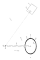
図4、図5の例の照明装置では、導光部材(導光拡散板)24を湾曲させることで、擬似白色光の配光を制御することができる。具体的に、例えば図6に示すように、支柱22の一端を天井などに設置し、壁に掛けられている絵画などの作品90を照明するのに、湾曲した導光部材(導光拡散板)24を用いることで、壁に掛けられている絵画などの作品90に適した良好な照明を行うことができる。   4 and 5, the light distribution of pseudo white light can be controlled by curving the light guide member (light guide diffusion plate) 24. Specifically, as shown in FIG. 6, for example, a curved light guide member (light guide diffuser plate) is used to illuminate a work 90 such as a picture hung on a wall by installing one end of a column 22 on a ceiling or the like. ) 24, it is possible to provide good illumination suitable for a work 90 such as a picture hung on a wall.

また、上述の各例では、励起光源部11からの励起光を反射して、支柱22内に所定の角度(励起光を支柱22内で全反射させながら導光させる角度)で入射させるための反射手段として、反射鏡26を支柱22内に設けたが(埋め込んだが)、例えば図7に示すように、反射鏡51、52を支柱22の外部(例えば天井裏など)に設け、励起光源部11からの励起光を反射鏡51、52により反射して、支柱22内に所定の角度(励起光を支柱22内で全反射させながら導光させる角度)で入射させるようにすることもできる。あるいは、人の出入りすることができる天井裏などであれば、天井裏などに励起光源部11を配置し、反射手段(反射鏡)を設けずに、励起光源部11からの励起光を直接、支柱22内に所定の角度(励起光を支柱22内で全反射させながら導光させる角度)で入射させるようにすることも可能である。   Further, in each of the above-described examples, the excitation light from the excitation light source unit 11 is reflected and incident on the support column 22 at a predetermined angle (the angle at which the excitation light is guided while being totally reflected in the support column 22). As the reflecting means, the reflecting mirror 26 is provided in the support column 22 (although embedded), but as shown in FIG. 7, for example, reflecting mirrors 51 and 52 are provided outside the support column 22 (for example, behind the ceiling), and the excitation light source unit. 11 can be reflected by the reflecting mirrors 51 and 52 so as to enter the support column 22 at a predetermined angle (the angle at which the excitation light is guided while being totally reflected in the support column 22). Or if it is the back of a ceiling where a person can go in and out, the excitation light source unit 11 is arranged on the back of the ceiling, and the excitation light from the excitation light source unit 11 is directly provided without providing a reflecting means (reflecting mirror). It is also possible to cause the light to enter the support 22 at a predetermined angle (the angle at which the excitation light is guided while being totally reflected in the support 22).

本発明は、一般照明などに利用可能である。   The present invention can be used for general lighting and the like.

1、31 照明装置
11 励起光源部
12 固体光源
21、41 受動発光部
22 支柱
23 蛍光体層
24 導光部材
25 反射部材
26 反射鏡
27 ハーフミラーまたはルーバー
51、52 反射鏡
DESCRIPTION OF SYMBOLS 1, 31 Illuminating device 11 Excitation light source part 12 Solid light source 21, 41 Passive light emission part 22 Support | pillar 23 Phosphor layer 24 Light guide member 25 Reflective member 26 Reflective mirror 27 Half mirror or louver 51, 52 Reflective mirror

Claims (5)

紫外光から可視光までの波長領域のうちの所定の波長の光を励起光として発光する固体光源を有する励起光源部と、該励起光源部とは空間的に離れた位置に設置され、該励起光源部の前記固体光源から出射された励起光が空中伝送により入射するときに、入射した励起光に基づいて照明光を出射する受動発光部とを備えた照明装置であって、前記受動発光部は、該受動発光部を支えるとともに前記入射した励起光を導光する支柱と、該支柱内を導光した励起光により励起され該励起光の波長よりも長波長の蛍光を発光する少なくとも1種類の蛍光体を含む蛍光体層と、該蛍光体層で発光した蛍光と励起光とをあわせて導光させる導光部材とを有していることを特徴とする照明装置。 An excitation light source unit having a solid-state light source that emits light having a predetermined wavelength in a wavelength region from ultraviolet light to visible light as excitation light, and the excitation light source unit are installed at spatially separated positions. An illumination device comprising: a passive light emitting unit that emits illumination light based on incident excitation light when excitation light emitted from the solid state light source of the light source unit is incident by air transmission, the passive light emitting unit Is a column that supports the passive light-emitting unit and guides the incident excitation light, and at least one kind that emits fluorescence having a wavelength longer than the wavelength of the excitation light that is excited by the excitation light guided in the column. And a light guide member that guides the fluorescence emitted from the phosphor layer and the excitation light together. 請求項1記載の照明装置において、前記受動発光部には、前記励起光源部からの励起光を反射して、前記支柱内に所定の角度で入射させるための反射手段がさらに設けられていることを特徴とする照明装置。 2. The illumination device according to claim 1, wherein the passive light emitting unit is further provided with reflecting means for reflecting the excitation light from the excitation light source unit so as to enter the column at a predetermined angle. A lighting device characterized by the above. 請求項1または請求項2に記載の照明装置において、前記励起光源部の前記固体光源には、励起光としてコヒーレント光を出射するものが用いられていることを特徴とする照明装置。 3. The illumination device according to claim 1, wherein the solid-state light source of the excitation light source unit is one that emits coherent light as excitation light. 4. 請求項1乃至請求項3のいずれか一項に記載の照明装置において、前記導光部材は、前記蛍光体層を取り囲んで設けられていることを特徴とする照明装置。 4. The lighting device according to claim 1, wherein the light guide member is provided so as to surround the phosphor layer. 5. 請求項1乃至請求項4のいずれか一項に記載の照明装置において、前記受動発光部は、発光面が鉛直下向きであることを特徴とする照明装置。 5. The lighting device according to claim 1, wherein a light emitting surface of the passive light emitting unit is vertically downward.
JP2011043897A 2011-03-01 2011-03-01 Lighting system Withdrawn JP2012182003A (en)

Priority Applications (1)

Application Number Priority Date Filing Date Title
JP2011043897A JP2012182003A (en) 2011-03-01 2011-03-01 Lighting system

Applications Claiming Priority (1)

Application Number Priority Date Filing Date Title
JP2011043897A JP2012182003A (en) 2011-03-01 2011-03-01 Lighting system

Publications (1)

Publication Number Publication Date
JP2012182003A true JP2012182003A (en) 2012-09-20

Family

ID=47013041

Family Applications (1)

Application Number Title Priority Date Filing Date
JP2011043897A Withdrawn JP2012182003A (en) 2011-03-01 2011-03-01 Lighting system

Country Status (1)

Country Link
JP (1) JP2012182003A (en)

Cited By (2)

* Cited by examiner, † Cited by third party
Publication number Priority date Publication date Assignee Title
CN103899954A (en) * 2014-03-12 2014-07-02 浙江阳光照明电器集团股份有限公司 LED bulb lamp capable of achieving automatic assembly
WO2021200128A1 (en) * 2020-03-31 2021-10-07 パナソニックIpマネジメント株式会社 Construction material, light radiating system, and illuminating system

Cited By (3)

* Cited by examiner, † Cited by third party
Publication number Priority date Publication date Assignee Title
CN103899954A (en) * 2014-03-12 2014-07-02 浙江阳光照明电器集团股份有限公司 LED bulb lamp capable of achieving automatic assembly
WO2021200128A1 (en) * 2020-03-31 2021-10-07 パナソニックIpマネジメント株式会社 Construction material, light radiating system, and illuminating system
US11852316B2 (en) 2020-03-31 2023-12-26 Panasonic Intellectual Property Management Co., Ltd. Construction component, light radiating system, and illumination system

Similar Documents

Publication Publication Date Title
JP5654447B2 (en) An illumination device comprising an LED and a transmissive support having a luminescent material.
JP6164843B2 (en) Illumination device having an envelope surrounding a light source
JP5464500B2 (en) Lighting device comprising an LED and one or more transmissive windows
EP2418415B1 (en) Spot light source and bulb-type light source
JP5468985B2 (en) Lighting device
WO2011132716A1 (en) Semiconductor light emitting device and production method for semiconductor light emitting device
KR20100077199A (en) Light emitting device with phosphor wavelength conversion
JP2012089316A (en) Light source device, and lighting system
JP2013102078A (en) Light source device and luminaire
JP6162537B2 (en) LIGHT SOURCE DEVICE, LIGHTING DEVICE, AND VEHICLE LIGHT
EP2653775A1 (en) Acoustic light emitting element
JP2012182009A (en) Lighting device
JP2012099222A (en) Light source device and lighting device
JP2013168602A (en) Light source device and luminaire
JP2012079989A (en) Light source device and lighting fixture
JP2007234639A (en) Light emitting device, and lighting system
JP2012182003A (en) Lighting system
JP5766521B2 (en) Lighting device
JP2013171623A (en) Light source device, and lighting device
JP2020177853A (en) Manufacturing method of light-emitting device, and light-emitting device
KR102400249B1 (en) Light emitting module and display including the module
RU2525166C2 (en) Method to control chromaticity of light flux of white light diode and device for method realisation
JP2008306013A (en) Illumination device
JP2024502707A (en) Laser SMD package with phosphor and optical in-coupler
KR101798569B1 (en) Lighting device

Legal Events

Date Code Title Description
RD04 Notification of resignation of power of attorney

Free format text: JAPANESE INTERMEDIATE CODE: A7424

Effective date: 20120912

A300 Withdrawal of application because of no request for examination

Free format text: JAPANESE INTERMEDIATE CODE: A300

Effective date: 20140513