JP2012160676A - Substrate work device - Google Patents
Substrate work device Download PDFInfo
- Publication number
- JP2012160676A JP2012160676A JP2011021283A JP2011021283A JP2012160676A JP 2012160676 A JP2012160676 A JP 2012160676A JP 2011021283 A JP2011021283 A JP 2011021283A JP 2011021283 A JP2011021283 A JP 2011021283A JP 2012160676 A JP2012160676 A JP 2012160676A
- Authority
- JP
- Japan
- Prior art keywords
- module
- electric field
- power
- base
- field coupling
- Prior art date
- Legal status (The legal status is an assumption and is not a legal conclusion. Google has not performed a legal analysis and makes no representation as to the accuracy of the status listed.)
- Granted
Links
- 239000000758 substrate Substances 0.000 title claims abstract description 21
- 238000010168 coupling process Methods 0.000 claims abstract description 96
- 230000008878 coupling Effects 0.000 claims abstract description 95
- 238000005859 coupling reaction Methods 0.000 claims abstract description 95
- 230000005684 electric field Effects 0.000 claims abstract description 89
- 230000005540 biological transmission Effects 0.000 claims abstract description 35
- 238000004891 communication Methods 0.000 claims description 35
- 230000008054 signal transmission Effects 0.000 description 4
- 238000012423 maintenance Methods 0.000 description 3
- 239000003990 capacitor Substances 0.000 description 2
- 230000000694 effects Effects 0.000 description 2
- 230000032258 transport Effects 0.000 description 2
- 238000007689 inspection Methods 0.000 description 1
- 238000009434 installation Methods 0.000 description 1
- 229910000679 solder Inorganic materials 0.000 description 1
Images


Classifications
-
- H—ELECTRICITY
- H05—ELECTRIC TECHNIQUES NOT OTHERWISE PROVIDED FOR
- H05K—PRINTED CIRCUITS; CASINGS OR CONSTRUCTIONAL DETAILS OF ELECTRIC APPARATUS; MANUFACTURE OF ASSEMBLAGES OF ELECTRICAL COMPONENTS
- H05K13/00—Apparatus or processes specially adapted for manufacturing or adjusting assemblages of electric components
- H05K13/08—Monitoring manufacture of assemblages
- H05K13/0885—Power supply
Abstract
Description
本発明は、基板に対し所定の作業を行う基板作業装置に関し、例えば、部品実装ヘッドにより部品供給装置から部品を採取し、部品実装位置に位置決めされた基板上に装着する部品実装装置に関する。 The present invention relates to a board working apparatus that performs a predetermined operation on a board, for example, to a component mounting apparatus that picks up a component from a component supply apparatus by a component mounting head and mounts it on a board positioned at a component mounting position.
例えば、特許文献1には、以下の部品供給装置が記載されている。この部品供給装置は、装置本体側に電力供給用の1次コイルが設けられ、部品供給カセット側に電力供給用の2次コイルが設けられている。部品供給カセットが部品取出し位置まで移動されると、1次コイルと2次コイルとが電磁的に結合する。そして、これらのコイルを通して装置本体側から部品供給カセット側に電力が供給される。また、電力供給用のコイルとは別に、部品供給カセット側に信号送信用の1次コイルが設けられ、装置本体側に信号送信用の2次コイルが設けられている。これらのコイルを通して部品供給カセット側から装置本体側に信号が送信される。 For example, Patent Document 1 describes the following component supply apparatus. In this component supply device, a primary coil for power supply is provided on the device main body side, and a secondary coil for power supply is provided on the component supply cassette side. When the component supply cassette is moved to the component removal position, the primary coil and the secondary coil are electromagnetically coupled. Then, electric power is supplied from the apparatus main body side to the component supply cassette side through these coils. In addition to the power supply coil, a signal transmission primary coil is provided on the component supply cassette side, and a signal transmission secondary coil is provided on the apparatus main body side. A signal is transmitted from the component supply cassette side to the apparatus main body side through these coils.
また、例えば、特許文献2には、以下の部品実装装置が記載されている。この部品実装装置には、一括台車側に設けられている複数のアクチュエータに対し、その種類に応じた電力量が供給可能な複数の電源が内蔵されている。そして、部品実装装置の制御装置は、一括台車側に設けられているアクチュエータの識別情報が記憶されたコネクタから電力供給対象のアクチュエータの種類を読取り、該アクチュエータに該当する電源を選択して電力を供給する。 For example, Patent Document 2 describes the following component mounting apparatus. This component mounting apparatus incorporates a plurality of power sources capable of supplying a power amount corresponding to the type to a plurality of actuators provided on the collective carriage side. Then, the control device of the component mounting apparatus reads the type of the actuator to be supplied from the connector storing the identification information of the actuator provided on the collective carriage side, selects the power supply corresponding to the actuator, and supplies power. Supply.
特許文献1に記載の発明では、電力供給に電磁結合方式を用いているため、1次コイルと2次コイルとの位置合わせを高精度に行わないと、電力供給の効率が著しく低下する。よって、これらのコイルの配置部分が複雑な構成となる傾向にある。また、電力供給用のコイルとは別に、信号送信用のコイルが必要であり、コイルの設置スペースを確保する必要があり、また、部品増によりコスト高となる傾向にある。また、特許文献2に記載の発明では、供給する電力量を変えるために複数の電源が必要であり、電源の設置スペースを確保する必要があり、また、部品増によりコスト高となる傾向にある。 In the invention described in Patent Document 1, since the electromagnetic coupling method is used for power supply, the efficiency of power supply is significantly reduced unless the positioning of the primary coil and the secondary coil is performed with high accuracy. Therefore, the arrangement part of these coils tends to be complicated. In addition to the power supply coil, a signal transmission coil is required, and it is necessary to secure a space for installing the coil, and the cost tends to increase due to an increase in parts. Further, in the invention described in Patent Document 2, a plurality of power sources are required to change the amount of power to be supplied, and it is necessary to secure an installation space for the power sources, and the cost tends to increase due to an increase in parts. .
本発明は上記事情に鑑みてなされたものであり、その目的は、簡易な構成により電力供給および信号送信が可能であり、単一の電源で供給電力量を調整可能な基板作業装置を提供することにある。 The present invention has been made in view of the above circumstances, and an object thereof is to provide a substrate working apparatus capable of supplying power and transmitting signals with a simple configuration and capable of adjusting the amount of power supplied by a single power source. There is.
上述した課題を解決するために、請求項1に係る発明の構成上の特徴は、基板に対し部品を装着する際に必要な作業を行う作業手段および該作業手段を制御する作業制御手段を有する1台以上のモジュールと、該モジュールを作業位置から水平方向に引出し可能に支持するベースと、該ベースに設けられ、少なくとも前記作業制御手段を動作させるための電力を出力する電力出力手段と、前記電力出力手段に接続され、前記モジュールの引出し方向に延在するように前記ベースに設けられた電界結合用送電部と、前記作業制御手段に接続され、前記モジュールの引出し方向に延在し、且つ前記電界結合用送電部と離間して少なくとも一部が対向するように前記モジュールに設けられた電界結合用受電部と、前記ベースに設けられ、前記電力を少なくとも前記作業制御手段に供給するために、前記電力出力手段から前記電界結合用送電部に供給される電力を前記電界結合用受電部に送電して受電させる電界結合制御手段と、を備えることである。 In order to solve the above-described problem, the structural feature of the invention according to claim 1 includes a working means for performing a work required when a component is mounted on the board, and a work control means for controlling the working means. One or more modules, a base that supports the modules so that the modules can be pulled out in a horizontal direction from a work position, power output means that is provided on the base and outputs at least power for operating the work control means, Connected to the power output means, and connected to the work control means, and connected to the work control means, and connected to the work control means, and extended in the pull-out direction of the module; A power receiving unit for electric field coupling provided in the module so as to be separated from the electric power transmission unit for electric field coupling and facing at least a part thereof, and provided in the base, Electric field coupling control means for transmitting the electric power supplied from the power output means to the electric field coupling power transmission unit to the electric field coupling power reception unit and receiving the power to supply to the work control means at least. It is.
請求項2に係る発明の構成上の特徴は、請求項1において、複数台の前記モジュールが、前記モジュールの引出し方向と直交する方向に並べて配置され、前記モジュールを前記ベースに対して引出して所定の作業を行う場合に、当該モジュールの前記電界結合用受電部および該電界結合用受電部と対向する前記電界結合用送電部とが前記電力供給が可能となるように構成されていることである。 A structural feature of the invention according to claim 2 is that, in claim 1, a plurality of the modules are arranged side by side in a direction perpendicular to the direction in which the modules are pulled out, and the modules are pulled out with respect to the base. When the operation is performed, the electric field coupling power receiving unit of the module and the electric field coupling power transmitting unit opposed to the electric field coupling power receiving unit are configured to be able to supply the electric power. .
請求項3に係る発明の構成上の特徴は、請求項1又は2において、前記モジュールを前記ベースに対して引出して所定の作業を行う場合の前記電力供給量は、引出す前の状態のときの前記電力供給量に比べて小さくなるように制御されることである。 The structural feature of the invention according to claim 3 is that, in claim 1 or 2, the power supply amount when the module is pulled out from the base to perform a predetermined work is the amount of power supply in the state before the pull-out. It is controlled to be smaller than the power supply amount.
請求項4に係る発明の構成上の特徴は、請求項1〜3の何れか一項において、前記モジュールおよび前記ベースには、前記電界結合用送電部および前記電界結合用受電部を介して相互に通信を行うモジュール用通信制御手段およびベース用通信制御手段が夫々設けられ、前記モジュール用通信制御手段は、少なくとも前記モジュールの識別情報を記憶するモジュール用記憶手段を備え、前記ベース用通信制御手段は、少なくとも前記モジュールの識別情報と前記モジュールの固有の特性値とが関連付けられたテーブルデータを記憶するベース用記憶手段を備え、前記モジュール用通信制御手段から前記モジュールの識別情報を取得し、該モジュールの識別情報に対応する前記モジュールの固有の特性値を特定し、該モジュールの固有の特性値に基づいて前記電力供給量を調整することである。 The structural feature of the invention according to claim 4 is that in any one of claims 1 to 3, the module and the base are mutually connected via the electric field coupling power transmission unit and the electric field coupling power reception unit. Module communication control means and base communication control means for communicating with each other, and the module communication control means includes at least module storage means for storing identification information of the module, and the base communication control means. Comprises base storage means for storing table data in which at least the module identification information and the characteristic value unique to the module are associated, and obtains the module identification information from the module communication control means, A unique characteristic value of the module corresponding to the module identification information is specified, and the unique characteristic value of the module It is to adjust the power supply amount based.
請求項5に係る発明の構成上の特徴は、請求項1〜4の何れか一項において、前記ベースは、少なくとも、前記モジュールを前記作業位置に位置決めするための位置決め手段を備えていることである。 A structural feature of the invention according to claim 5 is that, in any one of claims 1 to 4, the base includes at least positioning means for positioning the module at the working position. is there.
請求項1に係る発明においては、電界結合によりベースからモジュールへ電力を供給する構成としている。一般的に、電磁結合は、電磁結合用送電部と電磁結合用受電部とを高精度に位置合わせしないと、電力供給の効率が著しく低下する性質を有している。一方、電界結合は、電磁結合のように電界結合用送電部と電界結合用受電部とを高精度に位置合わせしなくても、電力供給の効率は低下し難い性質を有している。よって、送受電部の高精度な位置合わせが可能な位置合わせ手段は不要となり、簡易な構成により電力供給が可能な基板作業装置を構成することができる。 In the invention according to claim 1, power is supplied from the base to the module by electric field coupling. In general, electromagnetic coupling has a property that the efficiency of power supply is significantly reduced unless the electromagnetic coupling power transmitting unit and the electromagnetic coupling power receiving unit are aligned with high accuracy. On the other hand, the electric field coupling has a property that the efficiency of power supply is unlikely to be lowered even if the electric field coupling power transmitting unit and the electric field coupling power receiving unit are not accurately aligned as in the case of electromagnetic coupling. Therefore, there is no need for an alignment means capable of highly accurate alignment of the power transmission / reception unit, and a substrate working apparatus capable of supplying power can be configured with a simple configuration.
また、電界結合用送電部は、モジュールの引出し方向に延在するようにベースに設けられている。電界結合用受電部は、モジュールの引出し方向に延在し、且つ電界結合用送電部と離間して少なくとも一部が対向するようにモジュールに設けられている。よって、モジュールを引出して作業を行うような場合に電界結合用送電部と電界結合用受電部との重なりの程度を変化させることにより、単一の電源で作業に見合った電力量を供給することが可能である。そして、単一の電源となるので、装置コストを軽減することができる。 In addition, the electric field coupling power transmission unit is provided on the base so as to extend in the pull-out direction of the module. The electric field coupling power receiving unit is provided in the module so as to extend in the drawing direction of the module and to be separated from the electric field coupling power transmission unit and to be at least partially opposed. Therefore, when working by pulling out the module, the amount of electric power suitable for the work can be supplied from a single power source by changing the degree of overlap between the electric power transmission part for electric field coupling and the electric power receiving part for electric field coupling. Is possible. And since it becomes a single power supply, an apparatus cost can be reduced.
請求項2に係る発明においては、並べて配置されている複数台のモジュールをベースに対して引出して所定の作業を行う場合に、ベースからモジュールへ電力供給が可能となるように構成されている。複数台のモジュールが並べて配置されている場合、中間のモジュールにおいて所定の作業を行う際に、モジュールの両側に配置されているモジュールが干渉して調整作業に支障を来たすおそれがある。しかし、モジュールは、ベースに対して所定の作業を行う位置に引出し可能に構成され、さらに所定の作業を行う位置にてベースから電力供給可能に構成されているので、電力が必要な所定の作業をスムーズに行うことができる。また、送受電部を基板作業用および所定作業用の2つ設ける必要がなく、装置コストを軽減することができる。また、モジュールをベースに対して引出す場合、従来のように電源をオフにして配線を取外す作業が不要となり、所定の作業を行う際の作業負担が軽減される。 The invention according to claim 2 is configured such that power can be supplied from the base to the module when a plurality of modules arranged side by side are pulled out from the base to perform a predetermined work. When a plurality of modules are arranged side by side, when a predetermined operation is performed in an intermediate module, the modules arranged on both sides of the module may interfere with each other and interfere with the adjustment operation. However, the module is configured to be able to be pulled out to a position where a predetermined work is performed with respect to the base, and further configured to be able to supply power from the base at a position where the predetermined work is performed. Can be done smoothly. Further, it is not necessary to provide two power transmission / reception units for the substrate work and the predetermined work, and the apparatus cost can be reduced. Further, when the module is pulled out from the base, the work of turning off the power supply and removing the wiring as in the conventional case is not necessary, and the work load when performing a predetermined work is reduced.
請求項3に係る発明においては、モジュールをベースに対して引出したときのモジュールへの電力供給量は、引出す前の電力供給量に比べて小さくなるが、必要電力量も小さくなるので、その必要供給量の範囲内で電力供給ができ、供給ロスがなく省エネルギ効果を図ることができる。 In the invention according to claim 3, the power supply amount to the module when the module is pulled out with respect to the base is smaller than the power supply amount before pulling out, but the necessary power amount is also small. Electric power can be supplied within the range of the supply amount, there is no supply loss, and an energy saving effect can be achieved.
請求項4に係る発明においては、モジュールおよびベースには、相互に通信を行うモジュール用通信制御手段およびベース用通信制御手段が夫々設けられている。電界結合においては、信号の送受信が可能であることから、別の専用通信回路を設ける必要がなく、簡易な構成により信号送信が可能な基板作業装置を構成することができる。また、ベース用通信制御手段は、モジュール用通信制御手段からモジュールの識別情報を取得し、該モジュールの識別情報に対応するモジュールの固有の特性値を特定し、該モジュールの固有の特性値に基づいて電力供給量を調整する。これにより、モジュールを別のモジュールと交換等した場合に、交換等したモジュールの固有の特性値を再設定する作業が不要となり、作業工数を低減させることができる。 In the invention according to claim 4, the module and the base are respectively provided with a module communication control means and a base communication control means for communicating with each other. In electric field coupling, since signals can be transmitted and received, it is not necessary to provide another dedicated communication circuit, and a substrate working apparatus capable of transmitting signals can be configured with a simple configuration. Further, the base communication control means acquires module identification information from the module communication control means, specifies a unique characteristic value of the module corresponding to the module identification information, and based on the unique characteristic value of the module Adjust the power supply. Thereby, when a module is exchanged with another module, an operation of resetting the characteristic value unique to the exchanged module becomes unnecessary, and the number of work steps can be reduced.
請求項5に係る発明においては、ベースには、モジュールを作業位置に位置決めするための位置決め手段が設けられた構成となっている。これにより、作業者は、モジュールをベースに対して引出し、もしくは押込む動作のみで作業位置に位置決めすることができ、作業に迅速に取り掛かることができる。 In the invention according to claim 5, the base is provided with positioning means for positioning the module at the working position. Thus, the operator can position the module at the work position only by pulling out or pushing the module with respect to the base, and can quickly start work.
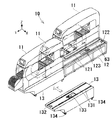
本発明の実施の形態の基板作業装置として、図1に示すように、部品実装装置10を例に説明する。部品実装装置10は、2台のモジュール11と、各モジュール11を作業位置(図1に示す状態)から水平方向(Y軸方向)に夫々引出し可能に支持する1台のベース12とから構成されている。モジュール11は、部品供給装置20、部品装着装置30、基板搬送装置50および制御装置40(本発明の「作業制御手段」に相当する)を備え、引出し方向(Y軸方向)と直交する方向(X軸方向)に2台並べて配置されている。部品供給装置20、部品装着装置30、制御装置40および基板搬送装置50は、既知の構成の装置であり、以下に概略構成を説明する。
As a substrate working apparatus according to an embodiment of the present invention, a
なお、図1では2台のモジュール11を1台のベース12上に引出し方向(Y軸方向)と直交する方向(X軸方向)に並べて配置した部品実装装置10を示すが、本発明は、1台のモジュール11を1台のベース12上に配置した部品実装装置10、もしくは複数台のモジュール11を1台のベース12上もしくは複数台のベース12上に引出し方向(Y軸方向)と直交する方向(X軸方向)に並べて配置した部品実装装置10に対しても適用可能である。
FIG. 1 shows a
部品供給装置20は、モジュール11の基枠11aに複数のフィーダ21を並設して構成したカセットタイプのものである。フィーダ21は、基枠11aに離脱可能に取付けたフィーダ本体22と、フィーダ本体22の後部に着脱可能に装着した供給リール23と、フィーダ本体22の先端に設けた部品供給部24とを備えている。供給リール23には、部品が所定ピッチで封入されたキャリアテープが巻回保持される。このような構成の部品供給装置20においては、スプロケット(図示省略)により供給リール23からキャリアテープが所定ピッチで引き出され、封入状態を解除された部品が部品供給部24に順次送り込まれる。
The
部品装着装置30は、XYロボットからなり、XYロボットは、モジュール11の基台11b上に装架されて基板搬送装置50および部品供給装置20の上方に配設されている。XYロボットは、Y軸方向に移動可能なY軸スライド31およびX軸方向に移動可能なX軸スライド32を備えている。X軸スライド32上には、図略の吸着ノズルを備えた部品装着ヘッド33が設けられている。また、基台11b上には、部品認識用カメラ34が固定されている。このような構成の部品装着装置30においては、吸着ノズルに吸着された部品は、部品認識用カメラ34により部品供給装置20の部品供給部24から基板S上の所定位置に移動する途中で撮像される。そして、吸着ノズルの中心に対する部品の芯ずれ等が検出され、この芯ずれ等に基づいて部品装着ヘッド33のXY方向等の移動量が補正される。
The
制御装置40は、CPU、ROM、RAM、入出力インターフェースおよびそれらを接続するバスを有するコンピュータ(図示省略)を主体とするものである。入出力インターフェースには、例えば、部品供給装置20および部品装着装置30に備えられている駆動モータM(図5参照)等を駆動するモータ駆動回路41(図5参照)等が接続されている。また、ROMには、例えば、部品実装を実行するための基本的な実装プログラム等が記憶されている。
The
基板搬送装置50は、一例として、2台の搬送装置51を並設したダブルコンベアタイプのものである。搬送装置51は、モジュール11の基台11b上にそれぞれ一対のガイドレール52を互いに平行に対向させてそれぞれ水平に並設し、これらガイドレール52によりそれぞれ案内される基板Sを支持して搬送する図略の一対のコンベアベルトを互いに対向させて並設して構成されている。また、基板搬送装置50には、所定位置に搬送された基板Sを持ち上げてクランプする図略のクランプ装置が設けられている。このような構成の基板搬送装置50においては、部品が実装される基板Sは、ガイドレール52により案内されつつコンベアベルトによりX軸方向に部品実装位置まで搬送される。そして、部品実装位置に搬送された基板Sは、クランプ装置によって部品装着位置に位置決めクランプされる。
As an example, the substrate transfer device 50 is of a double conveyor type in which two
次に、部品実装装置10のモジュール11およびベース12の構成について説明する。図2に示すように、モジュール11は、ベース12に対し固定可能、且つベース12に対し複数台のモジュール11の並び方向(X軸方向)と直交する方向(Y軸方向)に移動可能に搭載されている。すなわち、モジュール11は、モジュール11全体がベース12上に載置された状態(図2の奥側のモジュール11の状態)でベース12に対し固定される。この固定位置は、部品の実装作業が行われる作業位置である。
Next, the configuration of the
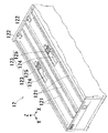
そして、モジュール11は、実装作業位置と、モジュール11内のメンテナンス等の作業を行う調整作業位置(図2の手前側の一点鎖線で示すモジュール11の位置)と、モジュール11をベース12から取外す取外し位置(図2の手前側の実線で示すモジュール11の位置)との間で移動可能に構成されている。モジュール11は、取外し位置に移動されたとき、ベース12の高さと同一高さに形成されているテーブル13(詳細は後述)上に載置される。これにより、各モジュール11を入替えて配置したり、複数台のモジュール11の並び方向の配置を任意に設定することができる。
The
図3に示すように、ベース12の上面には、二対のガイドレール121が、モジュール11の引出し方向(Y軸方向)に平行に延在するように配置されている。一方、図4に示すように、モジュール11の底面には、8つの車輪111が、引出し方向(Y軸方向)に4つずつ平行に2列に並んで軸受を介して回転可能に支承されている。2列の車輪111の間隔は、一対のガイドレール121の間隔と同一に設けられ、2列の各車輪111は、一対のガイドレール121に沿って転動可能に夫々係合する。一対のガイドレール121は、1台のモジュール11の引出し方向(Y軸方向)の移動を案内する。
As shown in FIG. 3, two pairs of
図3に示すように、ベース12の上面の一対のガイドレール121の間には、モジュール11を実装作業位置に位置決めするための位置決め部材122(本発明の「位置決め手段」に相当する)と、実装作業位置に位置決めした状態を維持するため、および調整作業位置に位置決めするための位置決め装置123(本発明の「位置決め手段」に相当する)とが設けられている。位置決め部材122は、X軸方向から見た形状が逆L字状に形成され、凸部が上方を向くようにしてベース12の上面の後端部に固定されている。位置決め装置123は、シリンダ装置124と、位置決め部材125とを備え、ベース12の略中央部に内蔵されている。
As shown in FIG. 3, between the pair of
図4に示すように、シリンダ装置124は、シリンダ本体124aの後端部がベース12の上面の裏側に回動自在に支承され、ロッド124bの先端部に位置決め部材125が回動自在に支承されている。位置決め部材125は、X軸方向から見た形状が逆くの字状に形成され、くの字の一端部がロッド124bの先端部に回動自在に支承され、くの字の中央部がベース12の上面の裏側に回動自在に支承されている。ロッド124bがシリンダ本体124aに対し突出し、もしくは引込むことにより、位置決め部材125がくの字の中央部を中心に反時計回りもしくは時計回りに回動し、位置決め部材125のくの字の他端部がベース12の上面に対し引込み、もしくは迫出すようになっている。
As shown in FIG. 4, in the
一方、図4に示すように、モジュール11の底面には、位置決め部材122および位置決め装置123の位置決め部材125と当接する当接部材112と、位置決め部材125に付勢される被付勢部材113とが設けられている。当接部材112は、直方体状に形成され、モジュール11の底面の後端部に固定されている。被付勢部材113は、直方体状に形成され、モジュール11の底面の略中央部に固定されている。
On the other hand, as shown in FIG. 4, the bottom surface of the
図4に示すように、作業者が、モジュール11を実装作業位置に移動すると、モジュール11の当接部材112がベース12の位置決め部材122に当接し、モジュール11の移動が規制される。すると、ベース12のシリンダ装置124が作動し、ロッド124bがシリンダ本体124aに対し引込み、位置決め部材125がベース12の上面から迫出し、モジュール11の被付勢部材113を位置決め部材122側に付勢する。これにより、モジュール11は、実装作業位置に位置決め固定される。
As shown in FIG. 4, when the operator moves the
モジュール11を実装作業位置から調整作業位置に移動するときは、ベース12のシリンダ装置124が作動し、ロッド124bがシリンダ本体124aに対し突出し、位置決め部材125が被付勢部材113から離間してベース12の上面から引込む。ここで、作業者は、モジュール11の被付勢部材113がベース12の位置決め部材125上を通り過ぎるまでモジュール11を引出す。すると、ベース12のシリンダ装置124が再度作動し、ロッド124bがシリンダ本体124aに対し引込み、位置決め部材125がベース12の上面から迫出す。そして、作業者は、モジュール11の当接部材112がベース12の位置決め部材125に当接するまでモジュール11を引出す。これにより、モジュール11は、調整作業位置に位置決めされる。
When the
モジュール11を調整作業位置から取外し位置に移動するときは、作業者は、テーブル13をベース12の前方に移動しておく。ここで、図2に示すように、テーブル13は、モジュール11のX軸方向の幅よりもやや大きな幅で、モジュール11のY軸方向の長さと略同じ長さで、ベース12の上面と略同じ高さの上面を有する構成となっている。テーブル13の上面には、一対のガイドレール131がベース12のガイドレール121と同一の断面形状で同一の間隔で設けられている。
When moving the
また、テーブル13の上面の一対のガイドレール131の間には、モジュール11をテーブル13の上面に位置決めするための位置決め部材132と、テーブル13の上面に位置決めした状態を維持するための位置決め装置133とが設けられている。位置決め部材132および位置決め装置133は、ベース12の位置決め部材122および位置決め装置123と同一構成であり、詳細な説明は省略する。また、テーブル装置13の下部には、車輪134が設けられ、人力で容易に移動可能に構成されている。
Further, between the pair of
このような構成のテーブル13の一対のガイドレール131が、ベース12の一対のガイドレール121を延長した状態となるように、テーブル13をベース12の前方に位置決め配置する。そして、ベース12のシリンダ装置124が作動し、ロッド124bがシリンダ本体124aに対し突出し、位置決め部材125がモジュール11の当接部材112から離間してベース12の上面から引込む。ここで、作業者は、モジュール11を引出し、ベース12からテーブル13に移動すると、モジュール11の底面の手前側に設けられている図略の当接部材がテーブル13の位置決め部材132に当接し、モジュール11の移動が規制される。すると、テーブル13の位置決め装置133が作動し、モジュール11の被付勢部材113を位置決め部材132側に付勢する。これにより、モジュール11は、テーブル13上に位置決め固定される。
The table 13 is positioned and disposed in front of the base 12 so that the pair of
次に、図5を参照して、部品実装装置10の電力系について説明する。この部品実装装置10には、電界結合によりベース12からモジュール11へ電力を供給する電力供給装置60が備えられている。この電力供給装置60は、電力出力部61と、電界結合制御部62と、電界結合用送電部63と、ベース用通信制御部64と、電界結合用受電部65と、モジュール用通信制御部66とを備えている。電力出力部61は、各モジュール11への電力供給が可能であるため、1つの電力出力部61がベース12に設けられている。電界結合制御部62、電界結合用送電部63およびベース用通信制御部64は、各モジュール11に対応してベース12に夫々設けられている。電界結合用受電部65およびモジュール用通信制御部66は、各モジュール11に夫々設けられている。
Next, the power system of the
電力出力部61は、例えば、周波数50Hz〜60Hzで電圧200Vの交流電源であり、1つで2台のモジュール11に備えられている各制御装置40のモータ駆動回路41等を動作させるための電力を出力する。
The power output unit 61 is, for example, an AC power supply with a frequency of 50 Hz to 60 Hz and a voltage of 200 V, and the power for operating the
電界結合制御部62は、例えば、電力出力部61からの交流の周波数を50Hz〜60Hzから100kHzに変換するインバータであり、電力を制御装置40に供給するために電力出力部61に接続され、電力出力部61から電界結合用送電部63に供給される電力を電界結合用受電部65に送電して受電させる。
The electric field
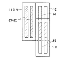
電界結合用送電部63は、帯状に形成された一対の電極であり、電界結合制御部62に接続され、図3に示すように、モジュール11の引出し方向に平行に延在するようにベース12の上面に設けられている。
The electric field coupling
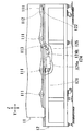
電界結合用受電部65は、帯状に形成された一対の電極であり、制御装置40のモータ駆動回路41等に接続され、モジュール11の引出し方向に延在し、且つモジュール11が実装作業位置に位置決めされた状態において電界結合用送電部63と離間して対向するようにモジュール11の底面に設けられている。すなわち、図6の左側のモジュール11およびベース12に示すように、モジュール11がベース12に対して実装作業位置に位置決めされているときは、電界結合用送電部63と電界結合用受電部65とは、Z軸方向から見た場合に略全体(図示斜線部分)が重なり合っている。よって、電力供給装置60は、電界結合によりベース12からモジュール11への送電量が最大となり、実装作業に必要な電力を供給することができる。
The electric field coupling
一方、図6の右側のモジュール11およびベース12に示すように、モジュール11がベース12に対して引出されて実装作業位置から調整作業位置に移動して位置決めされているときは、電界結合用送電部63と電界結合用受電部65とは、Z軸方向から見た場合に部分的(図示斜線部分)に重なり合っている。ここで、電界結合は、電界結合用送電部63と電界結合用受電部65とを高精度に位置合わせしなくても、電力供給の効率は低下し難い性質を有しており、両者の重なり度合いに比例した電力量が供給される。よって、電界結合制御部62を調整制御しなくても、電力供給装置60は、電界結合によりベース12からモジュール11へ、モジュールが実装作業位置に位置決めされたときよりは小さいが、調整作業に必要な電力を供給することができる。
On the other hand, when the
調整作業は実装作業よりも作動させる駆動モータ等の数が少ないため、調整作業に必要な電力は、実装作業に必要な電力よりも小電力でよい。電力供給装置60は、モジュール11が調整作業位置に位置決めされ、調整作業が行われる場合の電力供給量は、モジュール11が実装作業位置に位置決めされ、実装作業が行われる場合の電力供給量に比べて小さくなるように制御すればよく、電界結合制御部62の出力電力を、モジュールが実装作業位置に位置決めされている場合より小さくなるように制御してもよい。
Since the adjustment work requires fewer drive motors and the like than the mounting work, the power required for the adjustment work may be smaller than the power required for the mounting work. In the power supply device 60, the power supply amount when the
ベース用通信制御部64は、シグナルジェネレータ641、レシーバ642およびベース用メモリ643を備えている。ベース用メモリ643には、モジュール11の識別情報とモジュール11の固有の特性値とが関連付けられたテーブルデータや、モジュール11における作業プログラム、例えば、部品実装プログラム等のバージョンアップデータが記憶されている。ベース用通信制御部64のシグナルジェネレータ641およびレシーバ642は、電界結合制御部62と一方の電界結合用送電部63との接続途中においてコンデンサカップリング67を介して接続され、例えば、1.5V〜5Vの電力が供給される。
The base communication control unit 64 includes a signal generator 641, a
モジュール用通信制御部66は、シグナルジェネレータ661、レシーバ662およびモジュール用メモリ663を備えている。モジュール用メモリ663には、モジュール11の識別情報や、モジュール11における作業プログラム、例えば、部品実装プログラム等が記憶されている。モジュール用通信制御部66のシグナルジェネレータ661およびレシーバ662は、制御装置40と一方の電界結合用受電部65との接続途中においてコンデンサカップリング68を介して接続され、例えば、1.5V〜5Vの電力が供給される。ベース用通信制御部64とモジュール用通信制御部66とは、電界結合用送電部63および電界結合用受電部65を介して相互に通信を行う。
The module communication control unit 66 includes a
次に、部品実装装置10の動作について説明する。基板に対する部品の実装作業を行う場合、モジュール11は実装作業位置に位置決め固定されている。この状態では、電界結合用送電部63と電界結合用受電部65とは、Z軸方向から見た場合に略全体が重なり合っており、実装作業に必要な大きな電力は、電界結合によりベース12からモジュール11へ供給することができる。
Next, the operation of the
ベース用通信制御部64は、モジュール用通信制御部66からモジュール11の識別情報を取得し、該モジュール11の識別情報に対応するモジュールの固有の特性値を特定する。そして、電界結合制御部62は、特定した特性値に基づいて電力供給量を制御する。これにより、部品供給装置20および部品装着装置30が作動され、部品実装が行われる。なお、ベース用通信制御部64は、必要に応じて、例えば電源投入時にモジュール用通信制御部66から部品実装プログラム等のバージョンアップデータを読み出して部品実装プログラム等をアップデートする。
The base communication control unit 64 acquires the identification information of the
部品供給装置20や部品装着装置30のメンテナンス等の調整作業を行う場合、作業者は、モジュール11をベース12に対して引出し、実装作業位置から調整作業位置に移動して位置決めする。この状態では、電界結合用送電部63と電界結合用受電部65とは、Z軸方向から見た場合に部分的に重なり合っており、調整作業に必要な小さな電力が、電界結合によりベース12からモジュール11へ供給することができる。これにより、作業者は、部品供給装置20や部品装着装置30のメンテナンス等の調整作業を行うことができる。なお、モジュール11毎にベース12側に電力出力部61を設けることにより、電界結合制御部62は、調整作業時に作動させる駆動モータ等に必要なだけの電力を供給するように制御してもよい。
When performing an adjustment operation such as maintenance of the
以上のように、本実施形態の部品実装装置10によれば、電界結合によりベース12からモジュール11へ電力を供給する構成としているので、電界結合用送電部63と電界結合用受電部65とを高精度に位置合わせしなくても、電力供給の効率は低下し難い。よって、送受電部63,65の高精度な位置合わせが可能な位置合わせ手段は不要となり、簡易な構成により電力供給が可能な部品実装装置10を構成することができる。
As described above, according to the
また、電界結合用送電部63は、モジュール11の引出し方向に延在するようにベース12に設けられ、電界結合用受電部65は、モジュール11の引出し方向に延在し、且つ電界結合用送電部63と離間して少なくとも一部が対向するようにモジュール11に設けられている。よって、モジュール11を引出して作業を行うような場合に電界結合用送電部63と電界結合用受電部65との重なりの程度を変化させることにより、単一の電力出力部61で作業に見合った電力量を供給することが可能である。そして、単一の電力出力部61となるので、装置コストを軽減することができる。
The electric field coupling
また、複数台のモジュール11が並べて配置されている場合、中間のモジュール11において調整作業を行う際に、モジュール11の両側に配置されているモジュール11が干渉して調整作業に支障を来たすおそれがある。しかし、モジュール11は、ベース12に対して調整作業を行う位置に引出し可能に構成され、さらに調整作業を行う位置にてベース12から電力供給可能に構成されているので、電力が必要な調整作業をスムーズに行うことができる。また、送受電部を実装作業用および調整作業用の2つ設ける必要がなく、装置コストを軽減することができる。また、モジュール11をベース12に対して引出す場合、従来のように電源をオフにして配線を取外す作業が不要となり、調整作業を行う際の作業負担が軽減される。
In addition, when a plurality of
また、モジュール11をベース12に対して引出したときのモジュール11への電力供給量は、引出す前の電力供給量に比べて小さくなるが、必要電力量も小さくなるので、その必要供給量の範囲内で電力供給ができ、供給ロスがなく省エネルギ効果を図ることができる。また、電界結合においては、信号の送受信が可能であることから、モジュール11およびベース12には、相互に通信を行うモジュール用通信制御部64およびベース用通信制御部66が夫々設けられている。よって、別の専用通信回路を設ける必要がなく、簡易な構成により信号送信が可能な部品実装装置10を構成することができる。
Further, the power supply amount to the
また、ベース用通信制御部66は、モジュール用通信制御部64からモジュール11の識別情報を取得し、該モジュール11の識別情報に対応するモジュール11の固有の特性値を特定する。よって、電界結合制御部62は、該モジュール11の固有の特性値に基づいて電力供給量を調整することができる。これにより、モジュール11を別のモジュール11と交換等した場合に、交換等したモジュール11の固有の特性値を再設定する作業が不要となり、作業工数を低減させることができる。また、ベース12には、モジュール11を実装作業位置もしくは調整作業位置に位置決めするための位置決め装置122,123が設けられているので、作業者は、モジュール11をベース12に対して引出し、もしくは押込む動作のみで実装作業位置もしくは調整作業位置に位置決めすることができ、実装作業もしくは調整作業に迅速に取り掛かることができる。
Further, the base communication control unit 66 acquires the identification information of the
なお、上述の実施形態では、基板作業装置として、部品実装装置10を例に説明したが、基板に半田ペーストを印刷する印刷機や、基板に実装された部品の状態を検査する検査機等にも、本発明を適用することができる。
In the above-described embodiment, the
10・・・部品実装装置、11・・・モジュール、111・・・車輪、112・・・当接部材、113・・・被付勢部材、12・・・ベース、121・・・ガイドレール、122・・・位置決め部材、123・・・位置決め装置、124・・・シリンダ装置、125・・・位置決め部材、20・・・部品供給装置、30・・・部品装着装置、40・・・制御装置、50・・・基板搬送装置、60・・・電力供給装置、61・・・電力出力部、62・・・電界結合制御部、63・・・電界結合用送電部、64・・・ベース用通信制御部、641・・・シグナルジェネレータ、642・・・レシーバ642、643・・・ベース用メモリ、65・・・電界結合用受電部、66・・・モジュール用通信制御部。
DESCRIPTION OF
Claims (5)
該モジュールを作業位置から水平方向に引出し可能に支持するベースと、
該ベースに設けられ、少なくとも前記作業制御手段を動作させるための電力を出力する電力出力手段と、
前記電力出力手段に接続され、前記モジュールの引出し方向に延在するように前記ベースに設けられた電界結合用送電部と、
前記作業制御手段に接続され、前記モジュールの引出し方向に延在し、且つ前記電界結合用送電部と離間して少なくとも一部が対向するように前記モジュールに設けられた電界結合用受電部と、
前記ベースに設けられ、前記電力を少なくとも前記作業制御手段に供給するために、前記電力出力手段から前記電界結合用送電部に供給される電力を前記電界結合用受電部に送電して受電させる電界結合制御手段と、を備えることを特徴とする基板作業装置。 One or more modules having work means for performing work necessary for mounting components on the substrate and work control means for controlling the work means;
A base that supports the module so that the module can be pulled out horizontally from the working position;
Power output means provided on the base and outputting power for operating at least the work control means;
An electric field coupling power transmission unit connected to the power output means and provided in the base so as to extend in a pull-out direction of the module;
An electric field coupling power receiving unit provided in the module, connected to the work control means, extending in a pull-out direction of the module, and spaced apart from the electric field coupling power transmission unit and facing at least a part thereof;
An electric field provided on the base and configured to transmit power supplied from the power output unit to the electric field coupling power transmission unit to the electric field coupling power reception unit to receive the power to at least the work control unit. A substrate working apparatus comprising: a coupling control unit;
複数台の前記モジュールが、前記モジュールの引出し方向と直交する方向に並べて配置され、
前記モジュールを前記ベースに対して引出して所定の作業を行う場合に、当該モジュールの前記電界結合用受電部および該電界結合用受電部と対向する前記電界結合用送電部とが前記電力供給が可能となるように構成されていることを特徴とする基板作業装置。 In claim 1,
A plurality of the modules are arranged side by side in a direction orthogonal to the pulling-out direction of the modules,
When the module is pulled out from the base to perform a predetermined work, the electric field coupling power receiving unit of the module and the electric field coupling power transmitting unit facing the electric field coupling power receiving unit can supply the electric power. It is comprised so that it may become. The board | substrate working apparatus characterized by the above-mentioned.
前記モジュールを前記ベースに対して引出して所定の作業を行う場合の前記電力供給量は、引出す前の状態のときの前記電力供給量に比べて小さくなるように制御されることを特徴とする基板作業装置。 In claim 1 or 2,
The power supply amount when the module is pulled out with respect to the base to perform a predetermined work is controlled so as to be smaller than the power supply amount in a state before being pulled out. Work equipment.
前記モジュールおよび前記ベースには、前記電界結合用送電部および前記電界結合用受電部を介して相互に通信を行うモジュール用通信制御手段およびベース用通信制御手段が夫々設けられ、
前記モジュール用通信制御手段は、少なくとも前記モジュールの識別情報を記憶するモジュール用記憶手段を備え、
前記ベース用通信制御手段は、少なくとも前記モジュールの識別情報と前記モジュールの固有の特性値とが関連付けられたテーブルデータを記憶するベース用記憶手段を備え、前記モジュール用通信制御手段から前記モジュールの識別情報を取得し、該モジュールの識別情報に対応する前記モジュールの固有の特性値を特定し、該モジュールの固有の特性値に基づいて前記電力供給量を調整することを特徴とする基板作業装置。 In any one of Claims 1-3,
The module and the base are respectively provided with module communication control means and base communication control means for communicating with each other via the electric field coupling power transmission unit and the electric field coupling power reception unit,
The module communication control means includes at least module storage means for storing identification information of the module,
The base communication control means includes base storage means for storing table data in which at least the module identification information and the characteristic value specific to the module are associated, and the module communication control means identifies the module. A substrate working apparatus characterized by acquiring information, specifying a characteristic value unique to the module corresponding to identification information of the module, and adjusting the power supply amount based on the characteristic value unique to the module.
前記ベースは、少なくとも、前記モジュールを前記作業位置に位置決めするための位置決め手段を備えていることを特徴とする基板作業装置。 In any one of Claims 1-4,
The substrate working apparatus according to claim 1, wherein the base includes at least positioning means for positioning the module at the working position.
Priority Applications (3)
| Application Number | Priority Date | Filing Date | Title |
|---|---|---|---|
| JP2011021283A JP5704944B2 (en) | 2011-02-03 | 2011-02-03 | Substrate working device |
| PCT/JP2012/050830 WO2012105309A1 (en) | 2011-02-03 | 2012-01-17 | Substrate board working apparatus |
| CN201280007227.8A CN103340030B (en) | 2011-02-03 | 2012-01-17 | Base board operation device |
Applications Claiming Priority (1)
| Application Number | Priority Date | Filing Date | Title |
|---|---|---|---|
| JP2011021283A JP5704944B2 (en) | 2011-02-03 | 2011-02-03 | Substrate working device |
Publications (2)
| Publication Number | Publication Date |
|---|---|
| JP2012160676A true JP2012160676A (en) | 2012-08-23 |
| JP5704944B2 JP5704944B2 (en) | 2015-04-22 |
Family
ID=46602529
Family Applications (1)
| Application Number | Title | Priority Date | Filing Date |
|---|---|---|---|
| JP2011021283A Active JP5704944B2 (en) | 2011-02-03 | 2011-02-03 | Substrate working device |
Country Status (3)
| Country | Link |
|---|---|
| JP (1) | JP5704944B2 (en) |
| CN (1) | CN103340030B (en) |
| WO (1) | WO2012105309A1 (en) |
Cited By (8)
| Publication number | Priority date | Publication date | Assignee | Title |
|---|---|---|---|---|
| WO2014125629A1 (en) * | 2013-02-15 | 2014-08-21 | 富士機械製造株式会社 | Electrostatic coupled noncontact power supply device |
| KR20150057923A (en) * | 2013-11-20 | 2015-05-28 | 삼성테크윈 주식회사 | A working machine |
| KR20150057926A (en) * | 2013-11-20 | 2015-05-28 | 삼성테크윈 주식회사 | An apparatus for mounting component |
| JPWO2018092192A1 (en) * | 2016-11-15 | 2019-08-08 | 株式会社Fuji | Non-contact power supply coupling unit, non-contact power supply device, and work machine |
| WO2019215781A1 (en) * | 2018-05-07 | 2019-11-14 | 株式会社Fuji | Movement operation module |
| JP2019216134A (en) * | 2018-06-11 | 2019-12-19 | 株式会社Fuji | Target substrate working machine |
| WO2020110319A1 (en) * | 2018-11-30 | 2020-06-04 | 株式会社Fuji | Substrate working machine |
| JP2022008893A (en) * | 2017-05-05 | 2022-01-14 | アーテーエム キューネス ゲゼルシャフト ミット ベシュレンクテル ハフツング | Mounting press, suction device for mounting press, and modular mounting press system |
Families Citing this family (3)
| Publication number | Priority date | Publication date | Assignee | Title |
|---|---|---|---|---|
| CN106714543B (en) * | 2017-02-24 | 2022-05-20 | 珠海市泽良电子有限公司 | Small-size circuit board chip mounter |
| EP3606311B1 (en) * | 2017-03-30 | 2022-03-09 | Fuji Corporation | Substrate processing machine |
| JP7035184B2 (en) * | 2018-06-13 | 2022-03-14 | 株式会社Fuji | Anti-board work machine |
Citations (6)
| Publication number | Priority date | Publication date | Assignee | Title |
|---|---|---|---|---|
| JPH09307283A (en) * | 1996-05-15 | 1997-11-28 | Sony Corp | Part feeder |
| JPH11317595A (en) * | 1998-02-24 | 1999-11-16 | Juki Corp | Part feeding system |
| JP2005347351A (en) * | 2004-05-31 | 2005-12-15 | Yamaha Motor Co Ltd | Mounting machine, feeder, and feeder retaining apparatus |
| JP2007207976A (en) * | 2006-02-01 | 2007-08-16 | Yamagata Casio Co Ltd | Component mounting device |
| JP2010161414A (en) * | 2002-07-19 | 2010-07-22 | Fuji Mach Mfg Co Ltd | Work system for substrate |
| JP2010283257A (en) * | 2009-06-08 | 2010-12-16 | Juki Corp | Electronic component mounting apparatus |
Family Cites Families (1)
| Publication number | Priority date | Publication date | Assignee | Title |
|---|---|---|---|---|
| CN100508721C (en) * | 2002-06-25 | 2009-07-01 | 富士机械制造株式会社 | Substrate operating system |
-
2011
- 2011-02-03 JP JP2011021283A patent/JP5704944B2/en active Active
-
2012
- 2012-01-17 WO PCT/JP2012/050830 patent/WO2012105309A1/en active Application Filing
- 2012-01-17 CN CN201280007227.8A patent/CN103340030B/en active Active
Patent Citations (6)
| Publication number | Priority date | Publication date | Assignee | Title |
|---|---|---|---|---|
| JPH09307283A (en) * | 1996-05-15 | 1997-11-28 | Sony Corp | Part feeder |
| JPH11317595A (en) * | 1998-02-24 | 1999-11-16 | Juki Corp | Part feeding system |
| JP2010161414A (en) * | 2002-07-19 | 2010-07-22 | Fuji Mach Mfg Co Ltd | Work system for substrate |
| JP2005347351A (en) * | 2004-05-31 | 2005-12-15 | Yamaha Motor Co Ltd | Mounting machine, feeder, and feeder retaining apparatus |
| JP2007207976A (en) * | 2006-02-01 | 2007-08-16 | Yamagata Casio Co Ltd | Component mounting device |
| JP2010283257A (en) * | 2009-06-08 | 2010-12-16 | Juki Corp | Electronic component mounting apparatus |
Cited By (19)
| Publication number | Priority date | Publication date | Assignee | Title |
|---|---|---|---|---|
| CN104995818A (en) * | 2013-02-15 | 2015-10-21 | 富士机械制造株式会社 | Electrostatic coupled noncontact power supply device |
| WO2014125629A1 (en) * | 2013-02-15 | 2014-08-21 | 富士機械製造株式会社 | Electrostatic coupled noncontact power supply device |
| JPWO2014125629A1 (en) * | 2013-02-15 | 2017-02-02 | 富士機械製造株式会社 | Electrostatic coupling type non-contact power feeding device |
| KR101915203B1 (en) | 2013-11-20 | 2018-11-05 | 한화에어로스페이스 주식회사 | A working machine |
| JP2015099877A (en) * | 2013-11-20 | 2015-05-28 | 三星テクウィン株式会社Samsung Techwin Co., Ltd | Component packaging machine |
| KR20150057926A (en) * | 2013-11-20 | 2015-05-28 | 삼성테크윈 주식회사 | An apparatus for mounting component |
| KR101864326B1 (en) * | 2013-11-20 | 2018-06-05 | 한화에어로스페이스 주식회사 | An apparatus for mounting component |
| KR20150057923A (en) * | 2013-11-20 | 2015-05-28 | 삼성테크윈 주식회사 | A working machine |
| JP2015099880A (en) * | 2013-11-20 | 2015-05-28 | 三星テクウィン株式会社Samsung Techwin Co., Ltd | Work machine |
| JPWO2018092192A1 (en) * | 2016-11-15 | 2019-08-08 | 株式会社Fuji | Non-contact power supply coupling unit, non-contact power supply device, and work machine |
| JP2022008893A (en) * | 2017-05-05 | 2022-01-14 | アーテーエム キューネス ゲゼルシャフト ミット ベシュレンクテル ハフツング | Mounting press, suction device for mounting press, and modular mounting press system |
| US11685084B2 (en) | 2017-05-05 | 2023-06-27 | Atm Gmbh | Mounting press, aspiration device for a mounting press, and modular mounting press system |
| WO2019215781A1 (en) * | 2018-05-07 | 2019-11-14 | 株式会社Fuji | Movement operation module |
| JPWO2019215781A1 (en) * | 2018-05-07 | 2021-02-12 | 株式会社Fuji | Mobile work module |
| JP7157564B2 (en) | 2018-06-11 | 2022-10-20 | 株式会社Fuji | Work machine for board |
| JP2019216134A (en) * | 2018-06-11 | 2019-12-19 | 株式会社Fuji | Target substrate working machine |
| JPWO2020110319A1 (en) * | 2018-11-30 | 2021-09-27 | 株式会社Fuji | Anti-board work machine |
| WO2020110319A1 (en) * | 2018-11-30 | 2020-06-04 | 株式会社Fuji | Substrate working machine |
| JP7097988B2 (en) | 2018-11-30 | 2022-07-08 | 株式会社Fuji | Anti-board work machine |
Also Published As
| Publication number | Publication date |
|---|---|
| WO2012105309A8 (en) | 2012-09-27 |
| JP5704944B2 (en) | 2015-04-22 |
| CN103340030A (en) | 2013-10-02 |
| CN103340030B (en) | 2016-05-18 |
| WO2012105309A1 (en) | 2012-08-09 |
Similar Documents
| Publication | Publication Date | Title |
|---|---|---|
| JP5704944B2 (en) | Substrate working device | |
| JP4846649B2 (en) | Electronic component mounting device | |
| JPWO2015037099A1 (en) | Substrate working system, working method, and feeder transfer method | |
| KR101489703B1 (en) | Mounting method of electronic component and surface mounting apparatus | |
| JPWO2018179147A1 (en) | Component mounting system | |
| JP5850656B2 (en) | Substrate transfer device | |
| EP2964007B1 (en) | Communication system and electronic component mounting device | |
| JP5845415B2 (en) | Attachment for feeder installation and feeder installation method | |
| JP6219838B2 (en) | Component mounter | |
| US9346625B2 (en) | Work system for substrates and working machine | |
| JP5507169B2 (en) | Electronic component mounting equipment | |
| JP5450338B2 (en) | Electronic component mounting machine | |
| JPWO2014049684A1 (en) | Feeder type parts supply device | |
| JP2010109291A (en) | Electronic component mounting method, electronic component mounting apparatus, and electronic component mounting order determination method in electronic component mounting apparatus | |
| JP4822282B2 (en) | Component mounting machine and method of using the same | |
| JP5946287B2 (en) | Component mounting device | |
| EP3334266B1 (en) | Component-mounting device | |
| CN113545184B (en) | Servo amplifier system | |
| KR20010025827A (en) | Surface Mounting Device and Mounting Method thereof | |
| JP7097988B2 (en) | Anti-board work machine | |
| US20230114864A1 (en) | Power supply shutoff device and power supply shutoff method | |
| CN110557938B (en) | Component mounting device | |
| CN114223320A (en) | Automatic configuration system for support pin of component mounting machine | |
| JP2023017728A (en) | Two-dimensional robot system for supplying assembly component to mounting machine | |
| JP2001291996A (en) | Modular part mounter |
Legal Events
| Date | Code | Title | Description |
|---|---|---|---|
| A621 | Written request for application examination |
Free format text: JAPANESE INTERMEDIATE CODE: A621 Effective date: 20140114 |
|
| A131 | Notification of reasons for refusal |
Free format text: JAPANESE INTERMEDIATE CODE: A131 Effective date: 20141125 |
|
| A521 | Request for written amendment filed |
Free format text: JAPANESE INTERMEDIATE CODE: A523 Effective date: 20150115 |
|
| TRDD | Decision of grant or rejection written | ||
| A01 | Written decision to grant a patent or to grant a registration (utility model) |
Free format text: JAPANESE INTERMEDIATE CODE: A01 Effective date: 20150203 |
|
| A61 | First payment of annual fees (during grant procedure) |
Free format text: JAPANESE INTERMEDIATE CODE: A61 Effective date: 20150224 |
|
| R150 | Certificate of patent or registration of utility model |
Ref document number: 5704944 Country of ref document: JP Free format text: JAPANESE INTERMEDIATE CODE: R150 |
|
| R250 | Receipt of annual fees |
Free format text: JAPANESE INTERMEDIATE CODE: R250 |
|
| S533 | Written request for registration of change of name |
Free format text: JAPANESE INTERMEDIATE CODE: R313533 |
|
| R350 | Written notification of registration of transfer |
Free format text: JAPANESE INTERMEDIATE CODE: R350 |
|
| R250 | Receipt of annual fees |
Free format text: JAPANESE INTERMEDIATE CODE: R250 |
|
| R250 | Receipt of annual fees |
Free format text: JAPANESE INTERMEDIATE CODE: R250 |
|
| R250 | Receipt of annual fees |
Free format text: JAPANESE INTERMEDIATE CODE: R250 |
|
| R250 | Receipt of annual fees |
Free format text: JAPANESE INTERMEDIATE CODE: R250 |
|
| R250 | Receipt of annual fees |
Free format text: JAPANESE INTERMEDIATE CODE: R250 |
|
| R250 | Receipt of annual fees |
Free format text: JAPANESE INTERMEDIATE CODE: R250 |