JP2012144178A - Electric vehicle - Google Patents
Electric vehicle Download PDFInfo
- Publication number
- JP2012144178A JP2012144178A JP2011004877A JP2011004877A JP2012144178A JP 2012144178 A JP2012144178 A JP 2012144178A JP 2011004877 A JP2011004877 A JP 2011004877A JP 2011004877 A JP2011004877 A JP 2011004877A JP 2012144178 A JP2012144178 A JP 2012144178A
- Authority
- JP
- Japan
- Prior art keywords
- vehicle body
- batteries
- battery
- vehicle
- electric vehicle
- Prior art date
- Legal status (The legal status is an assumption and is not a legal conclusion. Google has not performed a legal analysis and makes no representation as to the accuracy of the status listed.)
- Pending
Links
Images
Classifications
-
- B—PERFORMING OPERATIONS; TRANSPORTING
- B62—LAND VEHICLES FOR TRAVELLING OTHERWISE THAN ON RAILS
- B62K—CYCLES; CYCLE FRAMES; CYCLE STEERING DEVICES; RIDER-OPERATED TERMINAL CONTROLS SPECIALLY ADAPTED FOR CYCLES; CYCLE AXLE SUSPENSIONS; CYCLE SIDECARS, FORECARS, OR THE LIKE
- B62K11/00—Motorcycles, engine-assisted cycles or motor scooters with one or two wheels
- B62K11/02—Frames
- B62K11/10—Frames characterised by the engine being over or beside driven rear wheel
-
- B—PERFORMING OPERATIONS; TRANSPORTING
- B60—VEHICLES IN GENERAL
- B60R—VEHICLES, VEHICLE FITTINGS, OR VEHICLE PARTS, NOT OTHERWISE PROVIDED FOR
- B60R16/00—Electric or fluid circuits specially adapted for vehicles and not otherwise provided for; Arrangement of elements of electric or fluid circuits specially adapted for vehicles and not otherwise provided for
- B60R16/02—Electric or fluid circuits specially adapted for vehicles and not otherwise provided for; Arrangement of elements of electric or fluid circuits specially adapted for vehicles and not otherwise provided for electric constitutive elements
- B60R16/04—Arrangement of batteries
-
- B—PERFORMING OPERATIONS; TRANSPORTING
- B60—VEHICLES IN GENERAL
- B60L—PROPULSION OF ELECTRICALLY-PROPELLED VEHICLES; SUPPLYING ELECTRIC POWER FOR AUXILIARY EQUIPMENT OF ELECTRICALLY-PROPELLED VEHICLES; ELECTRODYNAMIC BRAKE SYSTEMS FOR VEHICLES IN GENERAL; MAGNETIC SUSPENSION OR LEVITATION FOR VEHICLES; MONITORING OPERATING VARIABLES OF ELECTRICALLY-PROPELLED VEHICLES; ELECTRIC SAFETY DEVICES FOR ELECTRICALLY-PROPELLED VEHICLES
- B60L50/00—Electric propulsion with power supplied within the vehicle
- B60L50/50—Electric propulsion with power supplied within the vehicle using propulsion power supplied by batteries or fuel cells
-
- H—ELECTRICITY
- H01—ELECTRIC ELEMENTS
- H01M—PROCESSES OR MEANS, e.g. BATTERIES, FOR THE DIRECT CONVERSION OF CHEMICAL ENERGY INTO ELECTRICAL ENERGY
- H01M10/00—Secondary cells; Manufacture thereof
- H01M10/60—Heating or cooling; Temperature control
- H01M10/65—Means for temperature control structurally associated with the cells
- H01M10/655—Solid structures for heat exchange or heat conduction
- H01M10/6551—Surfaces specially adapted for heat dissipation or radiation, e.g. fins or coatings
-
- H—ELECTRICITY
- H05—ELECTRIC TECHNIQUES NOT OTHERWISE PROVIDED FOR
- H05K—PRINTED CIRCUITS; CASINGS OR CONSTRUCTIONAL DETAILS OF ELECTRIC APPARATUS; MANUFACTURE OF ASSEMBLAGES OF ELECTRICAL COMPONENTS
- H05K7/00—Constructional details common to different types of electric apparatus
- H05K7/20—Modifications to facilitate cooling, ventilating, or heating
-
- B—PERFORMING OPERATIONS; TRANSPORTING
- B60—VEHICLES IN GENERAL
- B60K—ARRANGEMENT OR MOUNTING OF PROPULSION UNITS OR OF TRANSMISSIONS IN VEHICLES; ARRANGEMENT OR MOUNTING OF PLURAL DIVERSE PRIME-MOVERS IN VEHICLES; AUXILIARY DRIVES FOR VEHICLES; INSTRUMENTATION OR DASHBOARDS FOR VEHICLES; ARRANGEMENTS IN CONNECTION WITH COOLING, AIR INTAKE, GAS EXHAUST OR FUEL SUPPLY OF PROPULSION UNITS IN VEHICLES
- B60K1/00—Arrangement or mounting of electrical propulsion units
- B60K1/04—Arrangement or mounting of electrical propulsion units of the electric storage means for propulsion
-
- B—PERFORMING OPERATIONS; TRANSPORTING
- B60—VEHICLES IN GENERAL
- B60Y—INDEXING SCHEME RELATING TO ASPECTS CROSS-CUTTING VEHICLE TECHNOLOGY
- B60Y2200/00—Type of vehicle
- B60Y2200/10—Road Vehicles
- B60Y2200/12—Motorcycles, Trikes; Quads; Scooters
-
- B—PERFORMING OPERATIONS; TRANSPORTING
- B62—LAND VEHICLES FOR TRAVELLING OTHERWISE THAN ON RAILS
- B62K—CYCLES; CYCLE FRAMES; CYCLE STEERING DEVICES; RIDER-OPERATED TERMINAL CONTROLS SPECIALLY ADAPTED FOR CYCLES; CYCLE AXLE SUSPENSIONS; CYCLE SIDECARS, FORECARS, OR THE LIKE
- B62K2202/00—Motorised scooters
-
- B—PERFORMING OPERATIONS; TRANSPORTING
- B62—LAND VEHICLES FOR TRAVELLING OTHERWISE THAN ON RAILS
- B62K—CYCLES; CYCLE FRAMES; CYCLE STEERING DEVICES; RIDER-OPERATED TERMINAL CONTROLS SPECIALLY ADAPTED FOR CYCLES; CYCLE AXLE SUSPENSIONS; CYCLE SIDECARS, FORECARS, OR THE LIKE
- B62K2204/00—Adaptations for driving cycles by electric motor
-
- Y—GENERAL TAGGING OF NEW TECHNOLOGICAL DEVELOPMENTS; GENERAL TAGGING OF CROSS-SECTIONAL TECHNOLOGIES SPANNING OVER SEVERAL SECTIONS OF THE IPC; TECHNICAL SUBJECTS COVERED BY FORMER USPC CROSS-REFERENCE ART COLLECTIONS [XRACs] AND DIGESTS
- Y02—TECHNOLOGIES OR APPLICATIONS FOR MITIGATION OR ADAPTATION AGAINST CLIMATE CHANGE
- Y02E—REDUCTION OF GREENHOUSE GAS [GHG] EMISSIONS, RELATED TO ENERGY GENERATION, TRANSMISSION OR DISTRIBUTION
- Y02E60/00—Enabling technologies; Technologies with a potential or indirect contribution to GHG emissions mitigation
- Y02E60/10—Energy storage using batteries
Landscapes
- Engineering & Computer Science (AREA)
- Mechanical Engineering (AREA)
- Life Sciences & Earth Sciences (AREA)
- Sustainable Development (AREA)
- Electrochemistry (AREA)
- General Chemical & Material Sciences (AREA)
- Chemical & Material Sciences (AREA)
- Physics & Mathematics (AREA)
- Thermal Sciences (AREA)
- Microelectronics & Electronic Packaging (AREA)
- Manufacturing & Machinery (AREA)
- Chemical Kinetics & Catalysis (AREA)
- Sustainable Energy (AREA)
- Power Engineering (AREA)
- Transportation (AREA)
- Arrangement Or Mounting Of Propulsion Units For Vehicles (AREA)
- Battery Mounting, Suspending (AREA)
- Electric Propulsion And Braking For Vehicles (AREA)
- Axle Suspensions And Sidecars For Cycles (AREA)
- Secondary Cells (AREA)
- Cooling, Air Intake And Gas Exhaust, And Fuel Tank Arrangements In Propulsion Units (AREA)
Abstract
Description
本発明は、電動車両に係り、特に、車載バッテリの電力を電動モータに供給し、該電動モータの駆動力によって駆動輪を回転させて走行する電動車両に関する。 The present invention relates to an electric vehicle, and more particularly to an electric vehicle that travels by supplying electric power from an in-vehicle battery to an electric motor and rotating driving wheels by a driving force of the electric motor.
従来から、車載バッテリの電力を電動モータに供給し、該電動モータの駆動力によって駆動輪を回転させて走行する電動車両が知られている。 2. Description of the Related Art Conventionally, an electric vehicle that travels by supplying electric power from an in-vehicle battery to an electric motor and rotating driving wheels by the driving force of the electric motor is known.
特許文献1には、スクータ型の鞍乗型電動2輪車両において、車体に揺動可能に取り付けられたスイングアームの内部に電動モータを収納し、電動モータに電力を供給する複数の車載バッテリを、車体側の足乗せフロアの下部や荷物入れボックスの後部等に分散配置した構成が開示されている。
In
しかしながら、特許文献1に記載された技術では、車載バッテリが車体の各部に分散配置されているため、各車載バッテリに接続する配線が長くなると共に複雑な取り回しが必要となったり、車載バッテリを車体に固定するためのステーが複数必要になるという課題があった。一方、このような課題に対処するためにスイングアーム内に車載バッテリを集中配置しようとすると、走行中に発熱する車載バッテリ同士が近接配置されることで冷却が難しくなり、スイングアーム内の冷却を促進させる電動ファン等を設ける必要が生じるという課題があった。
However, in the technique described in
本発明の目的は、上記従来技術の課題を解決し、スイングアーム内に集中配置した車載バッテリを簡単な構造により効果的に冷却することができる電動車両を提供することにある。 An object of the present invention is to solve the above-described problems of the prior art and provide an electric vehicle capable of effectively cooling an in-vehicle battery centrally arranged in a swing arm with a simple structure.
前記目的を達成するために、本発明は、電動車両(1)の車体に揺動自在に取り付けられると共に、前記電動車両(1)の駆動輪(WR)を駆動する電動モータ(M)および略直方体のバッテリ(40a,40b)が収納されるスイングアーム(30)を備える電動車両において、前記スイングアーム(30,80,90)の揺動軸(19)寄りの位置に、前記バッテリ(40a,40b)を収納する幅広ケース部(34,84,94)が形成され、前記幅広ケース部(34,84,94)の天井部に、前記バッテリ(40a,40b)の上方に空気溜め空間(59a,82a,92a)を形成するための盛り上がり部(58,88,98)が形成されている点に第1の特徴がある。 In order to achieve the above object, the present invention is provided with an electric motor (M) that is swingably attached to a vehicle body of an electric vehicle (1), and that drives a drive wheel (WR) of the electric vehicle (1). In an electric vehicle including a swing arm (30) in which a rectangular parallelepiped battery (40a, 40b) is accommodated, the battery (40a, 40) is positioned at a position near the swing axis (19) of the swing arm (30, 80, 90). 40b) is formed, and a wide case part (34, 84, 94) is formed, and an air reservoir space (59a) above the battery (40a, 40b) is formed on the ceiling part of the wide case part (34, 84, 94). , 82a, 92a) has a first feature in that raised portions (58, 88, 98) are formed.
また、前記バッテリ(40a,40b)は、車体前後方向に2つ並んで配設されており、前記盛り上がり部(58)は、車体側面視で、前記バッテリ(40a,40b)をまたいで上方に凸の略山型とされている点に第2の特徴がある。 The two batteries (40a, 40b) are arranged side by side in the longitudinal direction of the vehicle body, and the raised portion (58) extends upward across the batteries (40a, 40b) in a side view of the vehicle body. The second feature is that it has a convex substantially mountain shape.
また、前記盛り上がり部(58)の表面に、放熱用のフィン(100,101)が設けられている点に第3の特徴がある。 A third feature is that a fin (100, 101) for heat dissipation is provided on the surface of the raised portion (58).
また、前記バッテリ(40a,40b)は、車体前後方向に2つ並ぶと共に、車体側面視で、車体前側に位置するバッテリ(40a)に対して、車体後側に位置するバッテリ(40b)が車体上方側にオフセットして配設されており、前記幅広ケース部(84)の天井部に前記盛り上がり部(88)を形成することで、車体前側に位置するバッテリ(40a)の上方に空気溜め空間(82a)が設けられる点に第4の特徴がある。 Further, two batteries (40a, 40b) are arranged in the longitudinal direction of the vehicle body, and the battery (40b) located on the rear side of the vehicle body is different from the battery (40a) located on the front side of the vehicle body in a side view of the vehicle body. An offset space is provided on the upper side, and the raised portion (88) is formed on the ceiling portion of the wide case portion (84), so that an air reservoir space is provided above the battery (40a) located on the front side of the vehicle body. There is a fourth feature in that (82a) is provided.
また、前記バッテリ(40a,40b)は、車体前後方向に2つ並ぶと共に、車体側面視で、互いに平行に車体後方側に傾斜して配設されており、前記幅広ケース部(94)の天井部に前記盛り上がり部(98)を形成することで、前記バッテリ(40a,40b)の上方に空気溜め空間(92a)が設けられる点に第5の特徴がある。 In addition, two batteries (40a, 40b) are arranged in the longitudinal direction of the vehicle body, and are arranged so as to be inclined in parallel to each other toward the rear side of the vehicle body when viewed from the side of the vehicle body, and the ceiling of the wide case portion (94). There is a fifth feature in that an air reservoir space (92a) is provided above the battery (40a, 40b) by forming the raised portion (98) in the portion.
また、前記バッテリ(40a,40b)は、車体前後方向に並ぶ2つの上下方向高さが等しくなるように傾斜して配設されている点に第6の特徴がある。 In addition, the battery (40a, 40b) has a sixth feature in that the batteries (40a, 40b) are arranged so as to be inclined so that two vertical heights arranged in the longitudinal direction of the vehicle body are equal.
また、車体前方から導いた走行風を前記盛り上がり部(58,88,98)に当てるための冷却ダクト(15)を具備する点に第7の特徴がある。 A seventh feature is that a cooling duct (15) is provided for applying traveling wind guided from the front of the vehicle body to the raised portions (58, 88, 98).
さらに、前記スイングアーム(30)の内部に、少なくとも、前記電動モータ(M)、前記バッテリ(40a,40b)、前記電動モータ(M)の駆動回路やバッテリ(40a,40b)の充電回路を有する基板(50)が収納されている点に第8の特徴がある。 Further, the swing arm (30) includes at least the electric motor (M), the battery (40a, 40b), a drive circuit for the electric motor (M), and a charging circuit for the battery (40a, 40b). The eighth feature is that the substrate (50) is accommodated.
第1の特徴によれば、スイングアームの揺動軸寄りの位置に、バッテリを収納する幅広ケース部が形成され、幅広ケース部の天井部に、バッテリの上方に空気溜め空間を形成するための盛り上がり部が形成されているので、バッテリで生じた熱がバッテリ上方の空気溜め空間に逃げやすくなると共に、車体上方に突出した盛り上がり部に走行風が当たりやすくなり、バッテリを収納する幅広ケース部の放熱が促進されることとなる。これにより、スイングアーム形状の工夫のみでバッテリの冷却効果を高めることが可能となり、複数のバッテリが集中配置される場合でも、冷却用の電動ファン等を取り付ける必要がなくなり、スイングアーム構造の複雑化を避けることができる。 According to the first feature, the wide case portion for storing the battery is formed at a position near the swing axis of the swing arm, and an air reservoir space is formed above the battery in the ceiling portion of the wide case portion. Since the raised part is formed, the heat generated by the battery can easily escape to the air reservoir space above the battery, and the running wind easily hits the raised part protruding above the vehicle body, so that the wide case part for storing the battery Heat dissipation will be promoted. This makes it possible to increase the cooling effect of the battery only by adjusting the shape of the swing arm, and even when multiple batteries are concentrated, it is not necessary to install an electric fan for cooling and the swing arm structure is complicated. Can be avoided.
また、バッテリの集中配置が可能となることで、バッテリに接続する配線等の簡略化が可能となり、例えば、2つの同型のバッテリを直列接続する場合には、両バッテリを直列接続するための配線であるバスバーの短縮も可能となる。 In addition, the centralized arrangement of the batteries enables simplification of the wiring to be connected to the battery. For example, when two batteries of the same type are connected in series, the wiring for connecting both batteries in series is possible. The bus bar can be shortened.
第2の特徴によれば、バッテリは、車体前後方向に2つ並んで配設されており、盛り上がり部は、車体側面視で、バッテリをまたいで上方に凸の略山型とされているので、前後のバッテリ間で温められた空気が車体上方側に収集しやすくなり、盛り上がり部を設けたことによる冷却効果がさらに向上する。 According to the second feature, two batteries are arranged side by side in the longitudinal direction of the vehicle body, and the bulging portion has a substantially mountain shape that protrudes upward across the battery in a side view of the vehicle body. The air warmed between the front and rear batteries is easily collected on the upper side of the vehicle body, and the cooling effect due to the provision of the raised portion is further improved.
第3の特徴によれば、盛り上がり部の表面に、放熱用のフィンが設けられているので、簡単な構造により、盛り上がり部の表面からの放熱効果がさらに高められる。 According to the 3rd characteristic, since the fin for thermal radiation is provided in the surface of the rising part, the heat dissipation effect from the surface of the rising part is further heightened with a simple structure.
第4の特徴によれば、バッテリは、車体前後方向に2つ並ぶと共に、車体側面視で、車体前側に位置するバッテリに対して、車体後側に位置するバッテリが車体上方側にオフセットして配設されており、幅広ケース部の天井部に盛り上がり部を形成することで、車体前側に位置するバッテリの上方に空気溜め空間が設けられるので、スイングアーム内のバッテリが、車体前後方向に近接配置されると共に車体上下方向にオフセット配置される場合でも、車体前側のバッテリの上部に形成される空気溜め空間によって冷却効果を高めることが可能となる。また、バッテリの側面に設けられるプラス端子およびマイナス端子が、車体側面視において車体上下方向に離間して設けられている場合には、両バッテリを直列接続するための配線であるバスバーを短縮することが可能となり、構造の簡略化を図ることができる。 According to the fourth feature, two batteries are arranged in the longitudinal direction of the vehicle body, and the battery located on the rear side of the vehicle is offset to the upper side of the vehicle with respect to the battery located on the front side of the vehicle in a side view of the vehicle body. By forming a raised part on the ceiling part of the wide case part, an air reservoir space is provided above the battery located on the front side of the vehicle body, so that the battery in the swing arm is close to the vehicle body in the longitudinal direction. Even when it is disposed and offset in the vertical direction of the vehicle body, the cooling effect can be enhanced by the air reservoir space formed in the upper part of the battery on the front side of the vehicle body. In addition, when the plus terminal and the minus terminal provided on the side surface of the battery are provided apart from each other in the vehicle body vertical direction when viewed from the side of the vehicle body, the bus bar that is the wiring for connecting the batteries in series is shortened. Therefore, the structure can be simplified.
第5の特徴によれば、バッテリは、車体前後方向に2つ並ぶと共に、車体側面視で、互いに平行に車体後方側に傾斜して配設されており、幅広ケース部の天井部に盛り上がり部を形成することで、バッテリの上方に空気溜め空間が設けられるので、2つのバッテリが傾斜して配設される場合でも、2つのバッテリの上部の空気溜め空間によって冷却効果を高めることができる。また、バッテリの側面に設けられるプラス端子およびマイナス端子が、車体側面視において車体上下方向に離間して設けられている場合には、両バッテリを直列接続するための配線であるバスバーを短縮することが可能となり、さらに構造の簡略化を図ることができる。 According to the fifth feature, two batteries are arranged in the front-rear direction of the vehicle body, and are arranged to be inclined toward the rear side of the vehicle body in parallel to each other in a side view of the vehicle body. Since the air reservoir space is provided above the battery, the cooling effect can be enhanced by the air reservoir space above the two batteries even when the two batteries are inclined. In addition, when the plus terminal and the minus terminal provided on the side surface of the battery are provided apart from each other in the vehicle body vertical direction when viewed from the side of the vehicle body, the bus bar that is the wiring for connecting the batteries in series is shortened. The structure can be further simplified.
第6の特徴によれば、バッテリは、車体前後方向に並ぶ2つの上下方向高さが等しくなるように傾斜して配設されているので、幅広ケース部の車体上下方向の寸法を低減して、スイングアーム上部の凸部を低く抑えることができ、これにより、スイングアームの揺動範囲を広げることができる。 According to the sixth feature, since the battery is inclined so that the two vertical heights aligned in the longitudinal direction of the vehicle body are equal, the size of the wide case portion in the vertical direction of the vehicle body is reduced. The convex part on the upper part of the swing arm can be kept low, whereby the swing range of the swing arm can be expanded.
第7の特徴によれば、車体前方から導いた走行風を盛り上がり部に当てるための冷却ダクトを具備するので、盛り上がり部に積極的に走行風を当てることが可能となり、幅広ケース部の冷却性能をより一層高めることができる。 According to the seventh feature, since the cooling duct for applying the traveling wind guided from the front of the vehicle body to the rising portion is provided, it becomes possible to positively apply the traveling wind to the rising portion, and the cooling performance of the wide case portion. Can be further increased.
第8の特徴によれば、スイングアームの内部に、少なくとも、電動モータ、バッテリ、電動モータの駆動回路やバッテリの充電回路を有する基板が収納されているので、電動車両において大きな発熱を伴う部品がスイングアーム内に収納されることとなり、スイングアームに設けた冷却構造によってこれらの発熱要素をすべて冷却することができる。これにより、車体側に冷却構造を設ける必要がなくなり車体構造の簡略化が可能となる。 According to the eighth feature, since the board having at least the electric motor, the battery, the drive circuit of the electric motor, and the battery charging circuit is housed in the swing arm, there are components that generate a large amount of heat in the electric vehicle. All the heat generating elements can be cooled by the cooling structure provided in the swing arm. Thereby, it is not necessary to provide a cooling structure on the vehicle body side, and the vehicle body structure can be simplified.
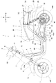
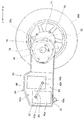
以下、図面を参照して本発明の好ましい実施の形態について詳細に説明する。図1は、本発明の一実施形態に係る電動車両1の側面図である。電動車両1は、低床フロア16を有するスクータ型の鞍乗型2輪車両であり、スイングアーム(ユニットスイング)30に収納された電動モータMによって後輪WRを駆動する。車体フレーム2の前部には、ステムシャフト(不図示)を回転自在に軸支するヘッドパイプ3が結合されている。ステムシャフトの上部には、ハンドルカバー11で覆われる操向ハンドル8が結合されており、一方の下部には、車軸7によって前輪WFを回動自在に軸支する左右一対のフロントフォーク6が結合されている。
Hereinafter, preferred embodiments of the present invention will be described in detail with reference to the drawings. FIG. 1 is a side view of an
車体フレーム2は、ヘッドパイプ3の後部から下方に延びるメインパイプ4と、該メインパイプ4の後端部に連結されて車体後部上方へ延びるリヤフレーム5とを備える。メインパイプ4において、低床フロア16の下部で車体前後方向に指向する部分には、低床フロア16を支持するフロアフレーム15が取り付けられている。メインパイプ4とリヤフレーム5との結合部には、左右一対のピボットプレート17が取り付けられている。
The
スイングアーム30は、車幅方向左側のみにアーム部を有する片持ち式であり、ピボットプレート17に取り付けられたリンク18を貫通する揺動軸19を介して、車体フレーム2に揺動自在に軸支されている。スイングアーム30は、アルミ等の金属からなる一部中空構造体であり、本体ケース31の車幅方向左側にスイングアームカバー35を取り付けた構成とされている。スイングアーム30の内部には、車軸32の近傍に電動モータMが収納され、電動モータMの車体前方側には、電動モータMの制御装置としての基板50が配設されている。電動モータMに電力を供給するバッテリ40a,40bは、車体前後方向に近接配置されると共に、スイングアーム30の車体前方寄りの位置で、かつ基板50の車幅方向右側に配設されている。基板50には、電動モータMの駆動回路や、外部電源からバッテリ40a,40bに充電するための充電回路、スロットル開度とモータ出力との関係を規定するデータマップを記憶したチップ等が含まれる。
The
スイングアーム30の本体ケース31には、車体前方寄りの位置に盛り上がり部58が形成されている。上方に凸形状を有する山型の盛り上がり部58は、バッテリ40a,40bの上方に位置しており、盛り上がり部58の車体前方には、冷却ダクト15の排出口15bが近接配置されている。パイプ状の部材からなる冷却ダクト15は、車体前方側の吸入口15aから取り入れた走行風を車体後方側へ導いて、その排出口15bから排出し、盛り上がり部58の表面を積極的に冷却する機能を有する。
The
後輪WRは、車軸32によってスイングアーム30に回転自在に軸支されており、スイングアーム30の後端部は、リヤクッション26を介してリヤフレーム5に吊り下げられている。また、シート20の下部には、荷物入れスペースとなる収納ボックス21が、左右一対のリヤフレーム5に挟まれるように配設されている。
The rear wheel WR is rotatably supported on the
車体フレーム2のメインパイプ4は、車体前方側のフロントカウル13および車体後方側のレッグシールド12で覆われている。ハンドルカバー11の上部には、メータ装置9が配設されており、メータ装置9の車体前方側には前照灯10が取り付けられている。フロントフォーク6の上部には、前輪WFを覆うフロントフェンダ14が固定されている。
The main pipe 4 of the
リヤフレーム5の車幅方向外側はシートカウル23で覆われており、シートカウル23の後端部には尾灯装置24が取り付けられている。尾灯装置24の上方には、リヤフレーム5に結合されたリヤキャリア22が突出しており、尾灯装置24の下方には、後輪WRの後方上方を覆うリヤフェンダ25が設けられている。
The outer side of the
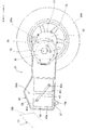
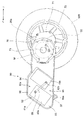
図2は、スイングアーム30の本体ケース31の拡大側面図である。また、図3は、本体ケース31の分解斜視図である。図2,3では、本体ケース31の車幅方向左側に取り付けられるスイングアームカバー35を取り外した状態を示している。本体ケース31の車体前方側には、略直方体のバッテリ40a,40bを収納するために車幅方向に広がった幅広ケース部34が形成されている。幅広ケース部34を構成する壁面は、その天井部を含めて薄板状部材で形成されている。車体前後方向に並ぶバッテリ40a,40bは、車幅方向左側に開口する収納空間59に対して、車幅方向左側から挿入されるように収められる。
FIG. 2 is an enlarged side view of the
幅広ケース部34の車体前方側下部には、揺動軸19(図1参照)の貫通孔19aが形成された左右一対のピボットフランジ37が設けられている。これにより、重量物としてのバッテリ40a,40bがスイングアーム30の揺動軸19に近接配置されることとなり、スイングアーム30の揺動時の慣性モーメントを低減してスムーズな揺動動作が可能となる。
A pair of left and
車幅方向左側のみに設けられるアーム部33の後端部には、電動モータMの回転を減速する減速機構が収納された減速機ケース71が取り付けられている。減速機構の最終出力軸となる車軸32は、減速機ケース71から車幅方向右側に向けて突出しており、この車軸32の端部に、後輪WRのホイール72が固定されている。一方、減速機ケース71の車幅方向左側には、電動モータMのロータ45が取り付けられる。また、減速機ケース71の上部には、リヤクッション26(図1参照)を取り付けるための貫通孔26aを有する取付フランジ70が設けられている。
A
リチウムイオンを用いて互いに同一構造とされるバッテリ40a,40bは、複数のセルからなるモジュール構造とされており、本実施形態では、車幅方向に5つのセルを並べて1つのモジュールが構成される。バッテリ40a,40bには、それぞれ、車幅方向左側の側面にプラス端子41a,41bおよびマイナス端子42a,42bが設けられている。電導体としてのバスバー43は、バッテリ40aのプラス端子41aとバッテリ40bのマイナス端子42bとを接続することで、両バッテリを直列接続する。マイナス側配線44の一端側は、バッテリ40aのマイナス端子42aに接続される。
The
幅広ケース部34の盛り上がり部58は、収納空間59の天井部を構成する薄板状部材を上方に突出させることで形成されている。これにより、収納されたバッテリ40a,40bの上部に、車体側面視で上方に凸の山型をなす空気溜め空間59aが形成される。
The raised
バッテリ40a,40bは、本体ケース31に形成された収納空間59内で車体前後方向に近接配置されるため、走行時に発生する熱が、特に、両バッテリの間にこもりやすくなる。しかしながら、本実施形態では、この熱が、両バッテリ40a,40bの上方に形成された空気溜め空間59aに逃げることができる。そして、空気溜め空間59aの熱は、盛り上がり部58の表面から車体外部に放熱されることとなり、これにより、バッテリ40a,40bの冷却効果が高められることとなる。さらに、本実施形態では、車体前方側から導入された走行風を盛り上がり部58に積極的に当てるための冷却ダクト15(図1参照)が設けられており、盛り上がり部58の表面からの放熱が促進される。なお、バッテリ40a,40bは、本体ケース31の車幅方向寸法を最小限に抑えるために、互いに車幅方向にはオフセットしないように配設されている。
Since the
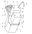
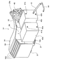
図4は、基板50およびステータ46の取付状態を示す本体ケース31の分解斜視図である。バッテリ40a,40bを所定位置に収納すると、本体ケース31には、両バッテリの車幅方向左側の側面に近接する仕切板56が複数のボルト等によって取り付けられる。仕切板56は樹脂等の絶縁部材からなり、バッテリ40aのマイナス端子42a(図3参照)に接続されたマイナス側配線44の他端側と、バッテリ40bのプラス端子41b(図3参照)に接続されたプラス側配線47の他端側のみが、仕切板56の上下に形成される隙間から車幅方向左側に突出するように構成されている。
FIG. 4 is an exploded perspective view of the
電動モータMのステータ46は、ロータ45を車幅方向左側から覆うようにして本体ケース31に固定される。ステータ46の車体前方側には基板50が配設される。基板50の車幅方向左側には多数の冷却フィン51が設けられており、基板50の車体前方側の端部には、車体側に取り回されるハーネス(不図示)を接続するためのコネクタ52,53が設けられている。電気配線としてのハーネスには、バッテリ40a,40bを外部電源(例えば、100Vの商用電源)によって充電するための配線のほか、前輪WFの回転速度を検知する車速センサ信号、イグニッションスイッチの操作信号等の配線を含めることができる。
The
基板50の車体前方側には、スロットルケーブル49によって駆動されるスロットル開度センサ48が配設される。スロットル開度センサ48は、ボルト等により仕切板56に固定される。スロットルケーブル49の端部は、車体フレーム2に沿って車体前方に取り回されて、操向ハンドル8(図1参照)に取り付けられて乗員が回動操作するスロットルグリップに接続される。
A
基板50は、その車体前方側が仕切板56に固定されると共に、車体後方側は本体ケース31にボルト等で固定される。基板50の車体後方側は、車体側面視でアーム部33とオーバーラップする位置まで伸びているため、基板50をボルトで固定することにより、基板50を本体ケース31の剛性メンバーとして利用して、アーム部33の剛性を高めることを可能としている。
The
ステータ46、基板50およびスロットル開度センサ48の取り付けが完了すると、基板50からステータ46に電力を供給するための3相バスバー54が取り付けられる。3相バスバー54は、基板50とステータ46とが近接配置されるために全長が短くて済み、これにより、送電時のロスやノイズの低減を図ることができる。スイングアームカバー35(図1参照)は、スイングアーム30内への水分や埃等の浸入を防ぐため、本体ケース31を密閉するように取り付けられる。
When the attachment of the
本実施形態では、電動モータM、バッテリ40a,40bおよび基板50からなる発熱要素がすべてスイングアーム30の内部に配置されている。このため、各要素の発熱により、スイングアーム30の内部空間の温度が上昇しやすくなるが、幅広ケース部34に設けられた盛り上がり部58によって冷却効果が高められていることで、その他の冷却構造が不要となり、車体構造の複雑化や部品点数の増加も防ぐことができる。
In the present embodiment, all of the heat generating elements including the electric motor M, the
図5は、本発明の第2実施形態に係るスイングアームの本体ケース80の拡大側面図である。前記と同一符号は、同一または同等部分を示す。本実施形態では、車体前方側に位置するバッテリ40aに対して、車体後方側に位置するバッテリ40bを車体上方にオフセット配置し、この配置に合わせて本体ケース80が形成されている点に特徴がある。
FIG. 5 is an enlarged side view of the
収納空間82を形成する幅広ケース部84の天井部には、車体上方にオフセット配置されるバッテリ40bが収納できるように車体上方に突出した盛り上がり部88が設けられている。これに伴い、車体前方側のバッテリ40aの上部に空気溜め空間82aが形成され、この空気溜め空間82aにより、バッテリ40a,40bに生じた熱が、幅広ケース部84の上面から放熱されやすくなり冷却効果が高められる。
On the ceiling portion of the
また、前側のバッテリ40aに対して後側のバッテリ40bが車体上方にオフセット配置されることにより、バッテリ40aのプラス端子41aとバッテリ40bのマイナス端子42bとを連結するバスバー89の長さを短縮することが可能となる。
Further, the
なお、後側のバッテリ40bの下部に形成される空間83は、各種電気機器の配設スペース等として利用することができる。なお、バッテリ40a,40bは、本体ケースの車幅方向寸法を最小限に抑えるために、互いに車幅方向にはオフセットしないように配設されている。また、不図示のスイングアームカバーは、本体ケース80に合わせた形状とされて本体ケース80を密閉するように構成されている。
In addition, the
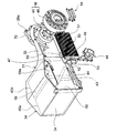
図6は、本発明の第3実施形態に係るスイングアームの本体ケース90の拡大側面図である。前記と同一符号は、同一または同等部分を示す。本実施形態では、略直方体のバッテリ40a,40bを、それぞれ、車体後方に傾斜させて配置すると共に、この配置に合わせて本体ケース90が形成されている点に特徴がある。
FIG. 6 is an enlarged side view of the
収納空間92を形成する幅広ケース部94の天井部には、車体後方に傾斜(車体後方側に所定角度回転)したバッテリ40a,40bが収納できるように、車体上方に突出した盛り上がり部98が設けられている。バッテリ40a,40bは、互いに平行かつ上下の位置が同じ高さになるように配設されており、これにより、バッテリ40aの後方上部かつバッテリ40bの前方上部に空気溜め空間92aが形成される。
On the ceiling portion of the
この空気溜め空間92aによれば、バッテリ40a,40bに生じた熱が、幅広ケース部94の上面から放熱されやすくなって冷却効果が高められる。また、前側のバッテリ40aの前方下部にも前側空気溜め空間93が形成され、この部分からの放熱効果も期待できる。なお、バッテリ40a,40bの下部側に形成される空間95は、各種電気機器の配設スペース等に利用できる。
According to the
また、バッテリ40a,40bが、それぞれ、車体後方に傾斜させて配置されることにより、バッテリ40aのプラス端子41aとバッテリ40bのマイナス端子42bとを連結するバスバー99の長さを短縮することが可能となる。なお、本実施形態においても、バッテリ40a,40bは、車幅方向にはオフセットしないように配設されており、不図示のスイングアームカバーは、本体ケース90に合わせた形状とされて本体ケース90を密閉するように構成されている。
Further, since the
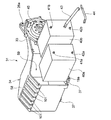
図7および図8は、本発明の一実施形態の変形例および第2変形例に係る本体ケース31の分解斜視図である。前記と同一符号は、同一または同等部分を示す。この変形例および第2変形例では、本体ケース31の幅広ケース部34に、冷却効果を高めるための冷却フィンが設けられている点に特徴がある。
7 and 8 are exploded perspective views of a
この変形例および第2変形例では、盛り上がり部58を形成する車体前方側の傾斜面、すなわち、冷却ダクト15(図1参照)から積極的に導入された走行風が当たる部分に冷却フィンを形成することで冷却効果を高めている。図7に示した冷却フィン100は、車幅方向に指向させたものであり、図8に示した冷却フィン101は、車体前後方向に指向させたものである。冷却フィン100,101は、本体ケース31と一体に形成するほか、別体式のフィン状の部材を取り付けることで構成してもよい。なお、このような冷却フィンは、盛り上がり部58の車体後方側の傾斜面や、幅広ケース部34の車体前方側の面、または、スイングアームカバー等に形成することもできる。
In this modified example and the second modified example, cooling fins are formed on the inclined surface on the front side of the vehicle body that forms the raised
上記したように、本発明に係る電動車両によれば、スイングアームに形成されてバッテリを収納するための幅広ケース部の天井部に、バッテリの上方に空気溜め空間を設けるための盛り上がり部を設けたので、バッテリで温められた空気が空気溜め空間に上って盛り上がり部の表面から放熱されやすくなる。これにより、幅広ケース部の形状の工夫のみでバッテリの冷却効果が高められ、幅広ケース内に複数のバッテリが近接配置される場合でも冷却用の電動ファン等を設ける必要がなくなり、スイングアーム構造の複雑化を避けることが可能となる。 As described above, according to the electric vehicle according to the present invention, the raised portion for providing the air storage space above the battery is provided on the ceiling portion of the wide case portion formed on the swing arm for storing the battery. Therefore, the air heated by the battery goes up to the air reservoir space and is easily radiated from the surface of the raised portion. As a result, the cooling effect of the battery can be enhanced only by devising the shape of the wide case part, and even when a plurality of batteries are arranged close to each other in the wide case, there is no need to provide an electric fan for cooling, etc. It becomes possible to avoid complication.
なお、電動車両の構造、スイングアームの形状や構造、スイングアームに設けられた幅広ケース部および盛り上がり部の形状や構造、バッテリの形状や構造、バッテリの配設位置、冷却ダクトの形状や配置等は、上記実施形態に限られず、種々の変更が可能である。例えば、両バッテリの間に仕切板を設けてもよい。本発明に係るスイングアーム構造は、電動二輪車に限られず、スイングアームを有する鞍乗型の三/四輪車等の各種車両に適用することが可能である。 In addition, the structure of the electric vehicle, the shape and structure of the swing arm, the shape and structure of the wide case portion and the raised portion provided on the swing arm, the shape and structure of the battery, the position of the battery, the shape and arrangement of the cooling duct, etc. The present invention is not limited to the above embodiment, and various modifications can be made. For example, a partition plate may be provided between both batteries. The swing arm structure according to the present invention is not limited to an electric motorcycle, and can be applied to various vehicles such as a straddle-type three / four-wheel vehicle having a swing arm.
1…電動車両、30,80,90…スイングアーム、33…アーム部、34,84,94…幅広ケース部、40a,40b…アーム部、58,88,98…盛り上がり部、59…収納空間、59a,82,92…空気溜め空間、WR…後輪
DESCRIPTION OF
Claims (8)
前記スイングアーム(30,80,90)の揺動軸(19)寄りの位置に、前記バッテリ(40a,40b)を収納する幅広ケース部(34,84,94)が形成され、
前記幅広ケース部(34,84,94)の天井部に、前記バッテリ(40a,40b)の上方に空気溜め空間(59a,82a,92a)を形成するための盛り上がり部(58,88,98)が形成されていることを特徴とする電動車両。 The electric vehicle (1) is swingably attached to the vehicle body, and houses the electric motor (M) that drives the drive wheels (WR) of the electric vehicle (1) and the substantially rectangular parallelepiped batteries (40a, 40b). In the electric vehicle including the swing arm (30),
Wide case portions (34, 84, 94) for accommodating the batteries (40a, 40b) are formed at positions near the swing axis (19) of the swing arms (30, 80, 90),
Swelling portions (58, 88, 98) for forming air reservoir spaces (59a, 82a, 92a) above the batteries (40a, 40b) at the ceiling of the wide case portions (34, 84, 94). An electric vehicle characterized in that is formed.
前記盛り上がり部(58)は、車体側面視で、前記バッテリ(40a,40b)をまたいで上方に凸の略山型とされていることを特徴とする請求項1に記載の電動車両。 Two of the batteries (40a, 40b) are arranged side by side in the longitudinal direction of the vehicle body,
2. The electric vehicle according to claim 1, wherein the raised portion (58) has a substantially mountain shape that protrudes upward across the battery (40 a, 40 b) in a side view of the vehicle body.
前記幅広ケース部(84)の天井部に前記盛り上がり部(88)を形成することで、車体前側に位置するバッテリ(40a)の上部に空気溜め空間(82a)が設けられることを特徴とする請求項1に記載の電動車両。 The two batteries (40a, 40b) are arranged in the longitudinal direction of the vehicle body, and the battery (40b) located on the rear side of the vehicle body is located on the upper side of the vehicle body with respect to the battery (40a) located on the vehicle body front side as viewed from the side of the vehicle body. It is arranged offset to
An air reservoir space (82a) is provided above the battery (40a) located on the front side of the vehicle body by forming the raised portion (88) in the ceiling portion of the wide case portion (84). Item 4. The electric vehicle according to Item 1.
前記幅広ケース部(94)の天井部に前記盛り上がり部(98)を形成することで、前記バッテリ(40a,40b)の上方に空気溜め空間(92a)が設けられることを特徴とする請求項1に記載の電動車両。 The batteries (40a, 40b) are arranged in two in the longitudinal direction of the vehicle body, and are arranged inclining toward the rear side of the vehicle body in parallel with each other in a side view of the vehicle body,
The air reservoir space (92a) is provided above the battery (40a, 40b) by forming the raised portion (98) in the ceiling portion of the wide case portion (94). The electric vehicle as described in.
Priority Applications (6)
| Application Number | Priority Date | Filing Date | Title |
|---|---|---|---|
| JP2011004877A JP2012144178A (en) | 2011-01-13 | 2011-01-13 | Electric vehicle |
| TW100147117A TWI461328B (en) | 2011-01-13 | 2011-12-19 | Electric vehicle |
| KR1020110145877A KR101335836B1 (en) | 2011-01-13 | 2011-12-29 | Motor driven vehicle |
| CN201210003047.4A CN102582406B (en) | 2011-01-13 | 2012-01-06 | Electric vehicle |
| US13/347,785 US8955627B2 (en) | 2011-01-13 | 2012-01-11 | Electric vehicle |
| DE102012200321.5A DE102012200321B4 (en) | 2011-01-13 | 2012-01-11 | electric vehicle |
Applications Claiming Priority (1)
| Application Number | Priority Date | Filing Date | Title |
|---|---|---|---|
| JP2011004877A JP2012144178A (en) | 2011-01-13 | 2011-01-13 | Electric vehicle |
Publications (1)
| Publication Number | Publication Date |
|---|---|
| JP2012144178A true JP2012144178A (en) | 2012-08-02 |
Family
ID=46471856
Family Applications (1)
| Application Number | Title | Priority Date | Filing Date |
|---|---|---|---|
| JP2011004877A Pending JP2012144178A (en) | 2011-01-13 | 2011-01-13 | Electric vehicle |
Country Status (6)
| Country | Link |
|---|---|
| US (1) | US8955627B2 (en) |
| JP (1) | JP2012144178A (en) |
| KR (1) | KR101335836B1 (en) |
| CN (1) | CN102582406B (en) |
| DE (1) | DE102012200321B4 (en) |
| TW (1) | TWI461328B (en) |
Cited By (10)
| Publication number | Priority date | Publication date | Assignee | Title |
|---|---|---|---|---|
| WO2014054204A1 (en) * | 2012-10-03 | 2014-04-10 | 川崎重工業株式会社 | Saddled electric vehicle |
| JP2014189144A (en) * | 2013-03-27 | 2014-10-06 | Honda Motor Co Ltd | Swing arm unit for electric vehicle |
| JP2016203955A (en) * | 2015-04-28 | 2016-12-08 | ヤマハ発動機株式会社 | Electric vehicle |
| JP2017081323A (en) * | 2015-10-27 | 2017-05-18 | スズキ株式会社 | Electric motorcycle drainage structure |
| WO2018061482A1 (en) * | 2016-09-29 | 2018-04-05 | 本田技研工業株式会社 | Electric motor cooling structure for saddle-type electric vehicle |
| WO2018179297A1 (en) * | 2017-03-30 | 2018-10-04 | 本田技研工業株式会社 | Battery support structure for saddle-type vehicle |
| WO2019207879A1 (en) * | 2018-04-25 | 2019-10-31 | 本田技研工業株式会社 | Electric vehicle |
| JP2019189053A (en) * | 2018-04-25 | 2019-10-31 | 本田技研工業株式会社 | Electric vehicle |
| WO2019235203A1 (en) * | 2018-06-07 | 2019-12-12 | ヤマハ発動機株式会社 | Electric vehicle and drive device for same |
| JPWO2021145276A1 (en) * | 2020-01-17 | 2021-07-22 |
Families Citing this family (21)
| Publication number | Priority date | Publication date | Assignee | Title |
|---|---|---|---|---|
| WO2010109969A1 (en) * | 2009-03-27 | 2010-09-30 | 本田技研工業株式会社 | Electric straddled vehicle |
| KR101286397B1 (en) * | 2010-08-31 | 2013-07-15 | 혼다 기켄 고교 가부시키가이샤 | Battery for electric vehicle |
| JP5460545B2 (en) * | 2010-09-30 | 2014-04-02 | 本田技研工業株式会社 | Battery module mounting structure for electric motorcycles |
| JP2014184827A (en) * | 2013-03-22 | 2014-10-02 | Yamaha Motor Co Ltd | Saddle-riding type vehicle |
| CN104925209A (en) * | 2015-06-25 | 2015-09-23 | 太仓市荣驰电机有限公司 | Battery and motor integrated electric bicycle |
| ES3058693T3 (en) * | 2017-08-22 | 2026-03-12 | Tvs Motor Co Ltd | Supporting structure for a two wheeled vehicle |
| CN111565988B (en) * | 2018-01-02 | 2025-03-11 | 福特全球技术公司 | Hybrid transmission |
| JP6971387B2 (en) * | 2018-04-02 | 2021-11-24 | 本田技研工業株式会社 | Electric vehicle |
| DE112019004274T5 (en) * | 2018-08-31 | 2021-05-20 | Honda Motor Co., Ltd. | Electric vehicle |
| DE102018217345A1 (en) * | 2018-09-12 | 2020-03-12 | Ziehl-Abegg Automotive Gmbh & Co. Kg | Wheel suspension and swing arm for a wheel driven by an electric or pneumatic motor |
| CR20210361A (en) * | 2018-12-13 | 2021-09-22 | Bajaj Auto Ltd | AN ELECTRIC VEHICLE |
| JP7113740B2 (en) | 2018-12-25 | 2022-08-05 | 本田技研工業株式会社 | saddle type electric vehicle |
| TWI733073B (en) * | 2018-12-28 | 2021-07-11 | 台達電子工業股份有限公司 | Driving mechanism |
| CN111377033B (en) | 2018-12-28 | 2021-10-01 | 台达电子工业股份有限公司 | Drive mechanism |
| CN110890492B (en) * | 2019-11-13 | 2024-03-29 | 广汽新能源汽车有限公司 | Battery pack, battery system and battery pack processing method |
| JP7347166B2 (en) * | 2019-11-29 | 2023-09-20 | スズキ株式会社 | saddle type vehicle |
| EP3939821A1 (en) * | 2020-07-17 | 2022-01-19 | Win Life Electric Vehicles, S.L. | Battery set for electric motorcycles |
| JP7502458B2 (en) * | 2020-10-30 | 2024-06-18 | 本田技研工業株式会社 | Work vehicle |
| JP7581794B2 (en) * | 2020-11-24 | 2024-11-13 | スズキ株式会社 | Battery |
| CN113335081B (en) * | 2021-08-05 | 2021-10-08 | 深圳市微卓通科技有限公司 | A battery fixing structure for a new energy vehicle |
| CN115056910A (en) * | 2022-08-05 | 2022-09-16 | 于海杰 | Side positive axis transmission electric motorcycle |
Family Cites Families (48)
| Publication number | Priority date | Publication date | Assignee | Title |
|---|---|---|---|---|
| FR2497734A1 (en) * | 1980-10-15 | 1982-07-16 | Peugeot Cycles | TWO WHEEL VEHICLE WITH ELECTRIC PROPULSION |
| CN1036258C (en) * | 1992-03-04 | 1997-10-29 | 本田技研工业株式会社 | motor vehicle |
| JP3493666B2 (en) | 1992-03-12 | 2004-02-03 | スズキ株式会社 | Electric scooter |
| JP3240080B2 (en) * | 1993-04-09 | 2001-12-17 | 本田技研工業株式会社 | Electric vehicle |
| JP2506047B2 (en) * | 1993-07-26 | 1996-06-12 | ヤマハ発動機株式会社 | Electric bicycle |
| US5524726A (en) * | 1995-04-18 | 1996-06-11 | Tenergy L.L.C. | Swing arm supported electrical drive assembly for powering cycles |
| JP3789613B2 (en) * | 1997-09-13 | 2006-06-28 | 本田技研工業株式会社 | Battery storage structure for motorcycles |
| US6047786A (en) * | 1997-12-11 | 2000-04-11 | Vectrix Corporation | Electric vehicle and frame therefor |
| CN2454188Y (en) * | 2000-10-16 | 2001-10-17 | 财团法人工业技术研究院 | Heat dissipation structure of electric vehicle |
| TWI222416B (en) * | 2001-06-25 | 2004-10-21 | Honda Motor Co Ltd | Electric vehicle |
| JP2004122981A (en) * | 2002-10-03 | 2004-04-22 | Yamaha Motor Co Ltd | Electric vehicle |
| JP2006240315A (en) * | 2003-05-20 | 2006-09-14 | Yamaha Motor Co Ltd | Saddle riding vehicle |
| US7249644B2 (en) * | 2003-05-30 | 2007-07-31 | Honda Motor Co., Ltd. | Electric vehicle |
| US7210550B2 (en) * | 2003-05-30 | 2007-05-01 | Honda Motor Co., Ltd. | Under-seat structure for a motorcycle |
| JP2005280656A (en) * | 2004-03-31 | 2005-10-13 | Honda Motor Co Ltd | Electric vehicle |
| JP2005297639A (en) * | 2004-04-07 | 2005-10-27 | Shirouma Science Co Ltd | Power assist bicycle with physical fitness improving functions |
| JP4278158B2 (en) * | 2004-05-18 | 2009-06-10 | 本田技研工業株式会社 | Battery mounting structure for electric vehicles |
| JP2006096105A (en) * | 2004-09-28 | 2006-04-13 | Honda Motor Co Ltd | Battery holding device for electric vehicle |
| KR20060037600A (en) * | 2004-10-28 | 2006-05-03 | 삼성에스디아이 주식회사 | Battery module and chiller for battery module |
| TW200810222A (en) * | 2005-12-28 | 2008-02-16 | Yamaha Motor Co Ltd | Fuel cell system and operating method thereof |
| US7588109B2 (en) * | 2006-04-28 | 2009-09-15 | Wachendorf Marvin J | Drill energized power module |
| US7882909B2 (en) * | 2006-09-14 | 2011-02-08 | University Of Pittsburgh | Personal vehicle |
| JP5052922B2 (en) | 2007-03-12 | 2012-10-17 | 本田技研工業株式会社 | Motorcycle |
| JP2008270191A (en) * | 2007-03-26 | 2008-11-06 | Yamaha Motor Co Ltd | Fuel cell system and operation method thereof |
| US7777451B2 (en) * | 2007-04-17 | 2010-08-17 | Chun-Chieh Chang | Rechargeable battery assembly and power system using same |
| JP5046382B2 (en) * | 2007-07-18 | 2012-10-10 | 本田技研工業株式会社 | Electric three-wheeled vehicle |
| JP2009047246A (en) * | 2007-08-20 | 2009-03-05 | Yamaha Motor Co Ltd | Saddle riding vehicle |
| JP2009161138A (en) * | 2008-01-10 | 2009-07-23 | Yamaha Motor Co Ltd | Motorcycle power supply support mechanism and motorcycle equipped with the same |
| US7855011B2 (en) * | 2008-08-28 | 2010-12-21 | International Battery, Inc. | Monoblock lithium ion battery |
| US8376075B2 (en) * | 2008-09-30 | 2013-02-19 | Honda Motor Co., Ltd. | Saddle-ride electric vehicle |
| TW201012669A (en) * | 2008-09-30 | 2010-04-01 | Honda Motor Co Ltd | Electric motorcycle |
| JP5084685B2 (en) * | 2008-09-30 | 2012-11-28 | 本田技研工業株式会社 | Straddle-type electric vehicle |
| JP5167054B2 (en) * | 2008-09-30 | 2013-03-21 | 本田技研工業株式会社 | Electric motorcycle |
| JP5167055B2 (en) * | 2008-09-30 | 2013-03-21 | 本田技研工業株式会社 | Electric motorcycle |
| JP5297183B2 (en) * | 2008-12-26 | 2013-09-25 | ヤマハ発動機株式会社 | Fuel cell system and transportation equipment including the same |
| WO2010109969A1 (en) * | 2009-03-27 | 2010-09-30 | 本田技研工業株式会社 | Electric straddled vehicle |
| US20110018378A1 (en) * | 2009-07-23 | 2011-01-27 | Stover Bobby A | Hybrid motor for transportation |
| JP2011035954A (en) * | 2009-07-29 | 2011-02-17 | Sanyo Electric Co Ltd | Motor drive and motor-driven vehicle for mounting the same |
| WO2011024326A1 (en) * | 2009-08-31 | 2011-03-03 | 本田技研工業株式会社 | Battery charger and battery charger attaching structure |
| JP5597376B2 (en) * | 2009-09-15 | 2014-10-01 | 本田技研工業株式会社 | Motorcycle |
| CN102082309B (en) * | 2009-11-27 | 2014-09-17 | 尹学军 | Method for quickly supplementing electric energy of electric vehicle and power supply unit thereof |
| EP2389797B1 (en) * | 2010-05-27 | 2014-11-19 | Kanzaki Kokyukoki Mfg. Co., Ltd. | Electric lawn mower |
| CN103140366B (en) * | 2010-11-12 | 2016-01-20 | 川崎重工业株式会社 | Mounting structure of power storage device for electric vehicle |
| US9132878B2 (en) * | 2010-11-18 | 2015-09-15 | Kawasaki Jukogyo Kabushiki Kaisha | Electric motorcycle |
| US8919481B2 (en) * | 2010-12-27 | 2014-12-30 | Kawasaki Jukogyo Kabushiki Kaisha | Saddle-type electric vehicle |
| CN103261015B (en) * | 2010-12-27 | 2016-11-23 | 川崎重工业株式会社 | electrical motorbike |
| US9090301B2 (en) * | 2010-12-27 | 2015-07-28 | Kawasaki Jukogyo Kabushiki Kaisha | Electric motorcycle |
| US9308957B2 (en) * | 2010-12-27 | 2016-04-12 | Kawasaki Jukogyo Kabushiki Kaisha | Saddle-type electric vehicle |
-
2011
- 2011-01-13 JP JP2011004877A patent/JP2012144178A/en active Pending
- 2011-12-19 TW TW100147117A patent/TWI461328B/en not_active IP Right Cessation
- 2011-12-29 KR KR1020110145877A patent/KR101335836B1/en not_active Expired - Fee Related
-
2012
- 2012-01-06 CN CN201210003047.4A patent/CN102582406B/en not_active Expired - Fee Related
- 2012-01-11 US US13/347,785 patent/US8955627B2/en active Active
- 2012-01-11 DE DE102012200321.5A patent/DE102012200321B4/en not_active Expired - Fee Related
Cited By (19)
| Publication number | Priority date | Publication date | Assignee | Title |
|---|---|---|---|---|
| US9308966B2 (en) | 2012-10-03 | 2016-04-12 | Kawasaki Jukogyo Kabushiki Kaisha | Saddle type electric vehicle |
| US9821882B2 (en) | 2012-10-03 | 2017-11-21 | Kawasaki Jukogyo Kabushiki Kaisha | Assembling method and assembling management method of electric vehicle |
| US9840306B2 (en) | 2012-10-03 | 2017-12-12 | Kawasaki Jukogyo Kabushiki Kaisha | Electric vehicle, and battery pack |
| WO2014054204A1 (en) * | 2012-10-03 | 2014-04-10 | 川崎重工業株式会社 | Saddled electric vehicle |
| US10259530B2 (en) | 2012-10-03 | 2019-04-16 | Kawasaki Jukogyo Kabushiki Kaisha | Assembling management system of electric vehicle and assembling method of electric vehicle |
| JP2014189144A (en) * | 2013-03-27 | 2014-10-06 | Honda Motor Co Ltd | Swing arm unit for electric vehicle |
| JP2016203955A (en) * | 2015-04-28 | 2016-12-08 | ヤマハ発動機株式会社 | Electric vehicle |
| JP2017081323A (en) * | 2015-10-27 | 2017-05-18 | スズキ株式会社 | Electric motorcycle drainage structure |
| US11414149B2 (en) | 2016-09-29 | 2022-08-16 | Honda Motor Co., Ltd. | Electric motor cooling structure for saddle-type electric vehicle |
| WO2018061482A1 (en) * | 2016-09-29 | 2018-04-05 | 本田技研工業株式会社 | Electric motor cooling structure for saddle-type electric vehicle |
| JPWO2018061482A1 (en) * | 2016-09-29 | 2019-04-11 | 本田技研工業株式会社 | Motor cooling structure for saddle-ride type electric vehicle |
| WO2018179297A1 (en) * | 2017-03-30 | 2018-10-04 | 本田技研工業株式会社 | Battery support structure for saddle-type vehicle |
| JP2019189053A (en) * | 2018-04-25 | 2019-10-31 | 本田技研工業株式会社 | Electric vehicle |
| JPWO2019207879A1 (en) * | 2018-04-25 | 2021-02-12 | 本田技研工業株式会社 | Electric vehicle |
| WO2019207879A1 (en) * | 2018-04-25 | 2019-10-31 | 本田技研工業株式会社 | Electric vehicle |
| WO2019235203A1 (en) * | 2018-06-07 | 2019-12-12 | ヤマハ発動機株式会社 | Electric vehicle and drive device for same |
| JPWO2021145276A1 (en) * | 2020-01-17 | 2021-07-22 | ||
| WO2021145276A1 (en) * | 2020-01-17 | 2021-07-22 | 本田技研工業株式会社 | Saddled electric vehicle |
| JP7292432B2 (en) | 2020-01-17 | 2023-06-16 | 本田技研工業株式会社 | saddle type electric vehicle |
Also Published As
| Publication number | Publication date |
|---|---|
| DE102012200321A1 (en) | 2012-07-19 |
| KR101335836B1 (en) | 2013-12-02 |
| CN102582406A (en) | 2012-07-18 |
| KR20120082342A (en) | 2012-07-23 |
| TW201238834A (en) | 2012-10-01 |
| TWI461328B (en) | 2014-11-21 |
| DE102012200321B4 (en) | 2014-07-03 |
| CN102582406B (en) | 2015-06-10 |
| US8955627B2 (en) | 2015-02-17 |
| US20120181097A1 (en) | 2012-07-19 |
Similar Documents
| Publication | Publication Date | Title |
|---|---|---|
| JP2012144178A (en) | Electric vehicle | |
| JP5352573B2 (en) | Electric vehicle | |
| US8997912B2 (en) | Electric motorcycle and controller unit | |
| US9660236B2 (en) | Battery and saddle-type electric vehicle equipped therewith | |
| EP2330025B1 (en) | Electric two-wheeled vehicle | |
| CN102556237B (en) | Electric motorcycle | |
| JP5225956B2 (en) | Electric saddle type vehicle | |
| US20150122570A1 (en) | Saddle-type electric vehicle | |
| EP3536531B1 (en) | Straddled vehicle | |
| CN111989260B (en) | Saddle-type electric vehicle | |
| WO2023127075A1 (en) | Saddled vehicle | |
| JP6428029B2 (en) | Swing arm for electric vehicle | |
| JP2010083363A (en) | Electric motorcycle | |
| JP7646036B2 (en) | Saddle type vehicle | |
| JPH11266508A (en) | Electric vehicle | |
| WO2023127136A1 (en) | Saddle-riding vehicle | |
| TW201518157A (en) | Electric motorcycle |