JP2006096105A - Battery holding device for electric vehicle - Google Patents
Battery holding device for electric vehicle Download PDFInfo
- Publication number
- JP2006096105A JP2006096105A JP2004282586A JP2004282586A JP2006096105A JP 2006096105 A JP2006096105 A JP 2006096105A JP 2004282586 A JP2004282586 A JP 2004282586A JP 2004282586 A JP2004282586 A JP 2004282586A JP 2006096105 A JP2006096105 A JP 2006096105A
- Authority
- JP
- Japan
- Prior art keywords
- battery
- vehicle body
- housing portion
- disposed
- vehicle
- Prior art date
- Legal status (The legal status is an assumption and is not a legal conclusion. Google has not performed a legal analysis and makes no representation as to the accuracy of the status listed.)
- Pending
Links
Images


Classifications
-
- Y02T10/7005—
Abstract
Description
本発明は、電動車両用バッテリ保持装置に関し、特に、大きいバッテリ容量を確保するのに好適な電動車両用バッテリ保持装置に関する。 The present invention relates to an electric vehicle battery holding device, and more particularly to an electric vehicle battery holding device suitable for securing a large battery capacity.
電動機の動力で駆動される電動車両や、電動機とエンジンとを混成した動力で駆動されるハイブリッド車両が知られる。このような電動車両では大容量のバッテリを搭載しなければならず、その設置スペースの確保が課題となっている。特に、余分な収納スペースが少ない自動二輪車では、バッテリの設置位置に苦慮することが考えられる。 There are known an electric vehicle driven by the power of an electric motor and a hybrid vehicle driven by a power obtained by hybridizing an electric motor and an engine. In such an electric vehicle, a large-capacity battery must be mounted, and securing the installation space has been a problem. In particular, in a motorcycle with little extra storage space, it can be considered that the installation position of the battery is difficult.
例えば、特許第3069808号明細書には、ステアリングシャフトを支持するヘッドパイプから後方斜め下方に延出するダウンフレームに沿ってバッテリを配置した電動二輪車が開示されている。この電動二輪車では、レッグシールドと乗員シートとの間にヘルメット等の収納ボックスを設けていて、バッテリはレッグシールドと収納ボックスのカバーとで囲まれたスペースに収納されている。
特許文献1に記載されているバッテリの配置では、バッテリ容量をさらに大きくしようとすると、レッグシールドと収納ボックスのカバーとの間のスペースが狭まり、乗員の足回りに余裕をもたせることが困難となる。そこで、足回りに十分なスペースを確保して乗員の乗り心地を損なわないようにしつつ、大容量のバッテリを収容できるバッテリ保持装置が望まれる。
In the battery arrangement described in
本発明の目的は、電動車両に適した大容量のバッテリを収容できるバッテリ保持装置を提供することにある。 An object of the present invention is to provide a battery holding device that can accommodate a large-capacity battery suitable for an electric vehicle.
前記目的を達成するための本発明は、車体の前部に配置された車体の前カバーおよびこの前カバーに対向して車体後方側に配置された後カバーの間にあって、バッテリを収容可能に形成したバッテリ収容部を有するバッテリケースを具備し、前記バッテリ収容部が、前記フロントフォークよりも車幅方向外側に位置して、車体の左右にそれぞれ設けられており、かつ、前記前カバーには、前記バッテリ収容部と対向する位置に空気取込口が設けられ、前記後カバーには、空気排出口が設けられている点に第1の特徴がある。 In order to achieve the above object, the present invention is formed between a front cover of a vehicle body arranged at the front portion of the vehicle body and a rear cover arranged on the rear side of the vehicle body facing the front cover so as to be able to accommodate a battery. A battery case having a battery housing portion, the battery housing portion is located on the outer side in the vehicle width direction than the front fork, and is provided on each of the left and right sides of the vehicle body, and the front cover includes A first feature is that an air intake port is provided at a position facing the battery housing portion, and an air discharge port is provided in the rear cover.
また、本発明は、前記バッテリケースが、前記ヘッドパイプに沿って配置された上収容部分と、前記ダウンフレームに沿って配置された下収容部分とからなる点に第2の特徴がある。 In addition, the present invention has a second feature in that the battery case is composed of an upper housing portion disposed along the head pipe and a lower housing portion disposed along the down frame.
また、本発明は、前記バッテリケースの上収容部分が、前記下収容部分より車体内側寄りに配置されている点に第3の特徴がある。 In addition, the present invention has a third feature in that the upper housing part of the battery case is disposed closer to the inside of the vehicle body than the lower housing part.
さらに、本発明は、前記バッテリ収容部とダウンフレームとの間に物入れ空間が形成されている点に第4の特徴がある。 Furthermore, the present invention has a fourth feature in that a storage space is formed between the battery housing portion and the down frame.
上記第1の特徴によれば、乗員の足回りのスペース確保とバッテリの大容量化を図りつつ、車両の走行中に空気取込口から走行風が取り込まれ、バッテリ収容部が走行風で冷却される。 According to the first feature, while ensuring the space around the passenger's legs and increasing the capacity of the battery, the traveling wind is taken in from the air intake port while the vehicle is traveling, and the battery housing portion is cooled by the traveling wind. Is done.
フロントフォークより外側に配置されたバッテリ収容部は、走行風をよりよく受けるので、バッテリの冷却効果が高い。また、フロントフォークとバッテリ収容部とが車体の前後方向で干渉しないので、バッテリ収容部をフロントフォークよりも前方に寄せて配置することができる。したがって、乗員の足回りのスペースを十分な広さにすることができる。 Since the battery accommodating part arrange | positioned outside a front fork receives driving | running | working wind better, the cooling effect of a battery is high. Further, since the front fork and the battery housing portion do not interfere with each other in the front-rear direction of the vehicle body, the battery housing portion can be disposed closer to the front than the front fork. Therefore, the space around the passenger's legs can be made sufficiently large.
第2の特徴によれば、バッテリケースの上収容部分と下収容部分を、ヘッドパイプおよびダウンフレームにそれぞれ沿わせて配置したので、車両の側面視において、車体フレームからの張り出しを小さくすることができる。したがって、例えば、二輪車のようにスペースが極めて制限される車両において大容量のバッテリを車両に搭載することができる。 According to the second feature, the upper housing portion and the lower housing portion of the battery case are arranged along the head pipe and the down frame, respectively, so that the overhang from the vehicle body frame can be reduced in a side view of the vehicle. it can. Therefore, for example, a large-capacity battery can be mounted on a vehicle such as a two-wheeled vehicle in which the space is extremely limited.
第3の特徴によれば、ヘッドパイプの近傍に配置したバッテリケースの上収容部分を車体内側寄りに配置することによって、ハンドル回りの車幅方向への張り出し部分を少なくすることができる。特に、小型のスクータ型車両において、スペースを効率よく利用することができる。 According to the third feature, by arranging the upper housing part of the battery case arranged in the vicinity of the head pipe closer to the inside of the vehicle body, the projecting part in the vehicle width direction around the handle can be reduced. In particular, in a small scooter type vehicle, space can be used efficiently.
第4の特徴によれば、バッテリ収容部をフロントフォークより外側に配置したので、バッテリ収容部とダウンフレームとの間を広くして物入れとして利用可能である。 According to the 4th characteristic, since the battery accommodating part has been arrange | positioned outside the front fork, it can be utilized as a container by widening between a battery accommodating part and a down frame.
以下、図面を参照して本発明の一実施形態を説明する。図1は本発明の一実施形態に係るバッテリ保持装置を備えたスクータの側面図である。このスクータは、内燃エンジンと電動機との混成動力で駆動されるハイブリッド型スクータである。 Hereinafter, an embodiment of the present invention will be described with reference to the drawings. FIG. 1 is a side view of a scooter including a battery holding device according to an embodiment of the present invention. This scooter is a hybrid scooter driven by hybrid power of an internal combustion engine and an electric motor.
図1に示したスクータ1の車体フレームは、ステアリングハンドル(以下、単に「ハンドル」という)2のシャフト2aを回動自在に支持するヘッドパイプ3と、ヘッドパイプ3から車体の後方斜め下向きに延びるダウンフレーム4と、このダウンフレーム4の下端から車体左右に分岐して後方へほぼ水平に延びる中間フレーム5と、この中間フレーム5の左右部分に渡されたクロスメンバ5aに連結されて、このクロスメンバ5aから車体の後方斜め上向きに延びる車体左右一対のリヤフレーム6とを備える。
The vehicle body frame of the
ヘッドパイプ3に軸支されたハンドル2のシャフト2aの下端には、ボトムブリッジ37で上端が連結されたフロントフォーク7が結合される。フロントフォーク7の下端には前輪8が軸支される。
A
エンジン9および電動機10、並びにベルト式無段変速装置11を含むパワーユニット12は、リヤフレーム6に対してリンク機構13によって上下に揺動自在に支持される。パワーユニット12には減速装置14を介して後輪15が連結される。パワーユニット12の後部とリヤフレーム6の後部との間には、これらパワーユニット12の後部とリヤフレーム6の後部とに上下端をそれぞれ結合されたリヤクッション16が設けられる。
The
エンジン9のクランク軸17には駆動プーリ18が結合され、駆動プーリ18と後輪側の従動プーリ19との間にはVベルト20が掛けられる。従動プーリ19を支持する従動軸21は減速装置14内の歯車装置を介して後輪15に連結される。
A drive pulley 18 is coupled to the
クランク軸17には、駆動プーリ18に隣接して発進クラッチが設けられるとともに、発進クラッチと反対側(車体右側)にはACGスタータ電動機が設けられる。発進クラッチおよびACGスタータ電動機は図示しない。
The
従動プーリ19と従動軸21とは、従動プーリ19の一方向(車両を前進させるための回転方向)の回転のみを従動軸21に伝達可能なように図示しないワンウェイクラッチを介して結合される。また、電動機10は従動軸21に近接配置され、電動機10のインナロータが従動軸21と一体に形成されている。
The driven
パワーユニット12において、エンジン9の動力は、クランク軸17から、発進クラッチ、無段変速装置11、ワンウェイクラッチ、従動軸21、および減速装置14を介して後輪15に伝達される。一方、エンジン9が休止しているときに電動機10を付勢して単独で後輪15を駆動できるし、エンジン9の運転中に電動機10を付勢してエンジン9の出力を補助することができる。
In the
リアフレーム6の上部には、乗員シート22が設けられる。乗員シート22の下方には、ヘルメット等を収納できる。リアフレーム6には、電動機10のドライバ回路としてのインバータ装置23やエンジン9およびACGスタータ電動機を制御するECU24が設けられる。
An
中間フレーム5には、エンジン9や灯火などの制御用電源として12ボルトの電圧を供給するバッテリ25が配置される。ヘッドパイプ3に接合されて車体の幅方向中央部に位置するダウンフレーム4の左右に、電動機10の駆動用電源としてのバッテリ組立体26が配置される。バッテリ組立体26は、側面視でほぼヘッドパイプ3に沿って配置される上部バッテリ群27と、ダウンフレーム4に沿って配置される下部バッテリ群28とからなる。すなわち、バッテリ組立体26は全体として、レッグシールド29を含むフロントカウル(前カバー)50に沿って収容されている。
The
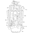
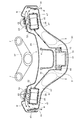
バッテリ組立体26の配置をさらに詳述する。図2は、スクータ1の車体前部の要部を示す左後方からの斜視図、図3は側面図、図4は車体前方からの正面図、図5は背面図、図6は図5のA−A位置での断面図である。
The arrangement of the
図2〜図6において、ヘッドパイプ3に接合されるダウンフレーム4を跨ぐように鞍型のバッテリケース30が配置される。バッテリケース30は、ダウンフレーム4を跨ぐ鞍部分31と、鞍部分31の裾野から車幅方向左右に延在するバッテリ収容部32とを有する。バッテリ収容部32は、円柱状の複数のバッテリ45が整列されてなる上部バッテリ群27および下部バッテリ群28をそれぞれ収容するのに適した嵌合凹部として形成される。バッテリ45は、例えば、ニッケル水素電池(Ni−MH電池)である。
2 to 6, a bowl-
バッテリケース30は、上部バッテリ群27および下部バッテリ群28をヘッドパイプ3およびダウンフレーム4にそれぞれ沿わせて配置できるように、上収容部32aと下収容部32bとの境を屈曲させている。すなわち、上収容部32aはほぼ垂直に、下収容部32bは上収容部32aの下端から車体後斜め下方に延びて、それぞれ配置される。
The
鞍部分31の頂部33には、バッテリ組立体26と電動機10との接続を行うためのリレーユニットやフューズ(後述する)が収容されるコンダクタユニット34が取り付けられる。
A
バッテリケース30のバッテリ収容部32の底部は、図4および図6に示すように、円柱状バッテリ45およびこの円柱状バッテリ45の両端を保持するバンド状ホルダ47の外形に適合するように半円状の波形が連続する部分を有して形成される。
As shown in FIGS. 4 and 6, the bottom of the
バッテリケース30には、上部バッテリ群27および下部バッテリ群28がバッテリ収容部32から脱出しないようにバッテリカバー35,36が被せられる。バッテリカバー35,36の形状も、バッテリ収容部32の底部と同様、バッテリ45およびバンド状ホルダ47の外形に適合するよう、半円状の波形が連続する部分を有して形成される。バッテリカバー35,36はそれぞれ別個のものであってもよいし、一体成型されていてもよい。
Battery covers 35 and 36 are placed on the
バッテリカバー35,36は、バッテリケース30に対して、例えば、ビス止めされる。ビス止めの例を図6に示す。バッテリケース30およびバッテリカバー36には、取り付けボス81,82がそれぞれ設けられる。締め付けビス83を取り付けボス82に設けられた孔に貫通させて取り付けボス81のねじ孔に螺合させることによってバッテリカバー36はバッテリケース30に固定される。
The battery covers 35 and 36 are screwed to the
図4および図5から理解できるように、バッテリケース30のバッテリ収容部32の下収容部32bは、上収容部32aよりも車幅方向に広がっており、ハンドル2のシャフト2aを支持するヘッドパイプ3からより遠く離れて位置している。車体左右の下収容部32bの間隔はフロントフォーク7の幅より大きく設定している。
As can be understood from FIGS. 4 and 5, the
このような配置により、バッテリケース30を車体前方寄りに寄せても、バッテリケース30の屈曲部がボトムブリッジ37に干渉しない。したがって、バッテリケース30は、レッグシールド29に沿って車体前方寄りに配置できる。
With such an arrangement, even if the
ダウンフレーム4の両側には、バッテリケース30の2個所の凹部38、38が左右対称に設けられる(図4参照)。この凹部38,38は、フロントフォーク7の頂部すなわちボトムブリッジ37の位置に対応しており、バッテリケース30を車体前方に寄せて配置した場合に、ボトムブリッジ37がバッテリケース30に当接しないように互いの間隔が設定される。
On both sides of the
バッテリ組立体26を収容するバッテリケース30を車体前方に寄せて配置することにより、バッテリケース30を車体後方側から覆うフロントカウル50のインナカバー(後カバー)42と乗員シート22との間隔を大きくでき、乗員の足回りの空間39を広くできるので、乗り心地が向上する(図3参照)。
By disposing the
図7は、図1のB−B位置での断面図である。図7において、コンダクタユニット34は、バッテリケース30の鞍部分31の頂部33に止めねじ40,40で取り付けられる。コンダクタユニット34にはセンタカバー41が被せられる。バッテリケース30の前方にはレッグシールド29が配置される。レッグシールド29は、車体前方をカバーするフロントカウル(前カバー)50の一部をなす。このレッグシールド29は、バッテリ収容部32の直前に位置させた空気取込口43,43を備えている。
FIG. 7 is a cross-sectional view taken along the line BB in FIG. In FIG. 7, the
一方、バッテリ組立体26やバッテリケース30を車体後方から覆うインナカバー(後カバー)42には、車幅方向両端に空気排出口44,44が設けられる。そして、バッテリケース30のバッテリ収容部32の前部にはフィン46が設けられ、バッテリ収容部32の外側表面積を大きくしている。これにより、スクータ1が走行中に受ける走行風Wが空気取込口43から流入し、フィン46に当たりながら通過し、空気排出口44から外部へ排出される。バッテリケース30は既述のように、バッテリ組立体26に沿うように形状が決定されている。つまりバッテリケース30とバッテリ組立体26とは密着している。したがって、レッグシールド29とインナカバー39とを通過する走行風Wにより、バッテリ45で発生した熱はバッテリケース30を介して放出され、バッテリ45の冷却効果が得られる。
On the other hand, the inner cover (rear cover) 42 that covers the
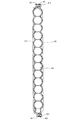
図8は、バッテリカバー35,36並びにセンタカバー41を取り外した状態の車体前部の背面図である。上部バッテリ群27および下部バッテリ群28は、バンド状ホルダ47で結束された複数のバッテリ45からなる。
FIG. 8 is a rear view of the front portion of the vehicle body with the battery covers 35 and 36 and the
車体の左右にそれぞれ設けられる上部バッテリ群27および下部バッテリ群28、並びにフューズ49およびリレーユニット51は直列に接続される。リレーユニット51から引き出されたプラス側コード52と左側の下部バッテリ群28から引き出されたマイナス側コード53とが接続用カプラ54に集合されている。
The
このように、本実施形態によれば、ハンドル2のシャフト2aの周囲からダウンフレーム4の周囲に亘る広い領域にバッテリを配置したので、電動二輪車の駆動用電動機に十分な電力を供給することができる。しかも、ヘッドパイプ3とダウンフレーム4の屈曲形状に沿わせつつ、かつレッグシールド29の左右端近くに配置してフロントフォーク7との干渉を避けてバッテリを配置したので、バッテリを車体前方に十分に寄せて配置できる。その結果、乗員の足回りのスペースに余裕を生じさせることができた。
Thus, according to the present embodiment, since the battery is arranged in a wide area extending from the periphery of the
図9は、物入れとして利用できるスペースを形成した例を示す図であり、図7と同符号は同一または同等部分である。図7では、インナカバー42はバッテリケース30の鞍型形状にほぼ沿うような形状に構成している。しかし、この変形例ではインナカバー42の形状を変形してインナカバー42とバッテリケース30との間をあけてスペースSを形成し、このスペースSを物入れとして利用することができるようにした。バッテリ収容部32を車体前方に寄せて配置できるようにしたことで、このように、レイアウトの自由度も出るようになった。
FIG. 9 is a diagram showing an example in which a space that can be used as a container is formed, and the same reference numerals as those in FIG. 7 denote the same or equivalent parts. In FIG. 7, the
上記実施形態では、本発明を二輪スクータに関して適用した。しかし、本発明は、これに限らず、ヘッドパイプおよびヘッドパイプから車体後方斜め下向きに延びるフレーム部材(ダウンフレームに相当する部材)を有する車両であれば、三輪車や四輪車にも適用可能である。また、ハイブリッド車に限らず電動機のみで車輪を駆動する電動車両にも同様に適用することができる。 In the above embodiment, the present invention is applied to a two-wheel scooter. However, the present invention is not limited to this, and can be applied to a three-wheeled vehicle or a four-wheeled vehicle as long as the vehicle has a head pipe and a frame member (a member corresponding to a down frame) that extends obliquely downward from the head pipe. is there. Further, the present invention is not limited to a hybrid vehicle and can be similarly applied to an electric vehicle in which wheels are driven only by an electric motor.
1…スクータ、 2…ヘッドパイプ、 4…ダウンフレーム、 5…中間フレーム、 7…フロントフォーク、 8…前輪、 9…エンジン、 10…電動機、 26…バッテリ組立体、 27…上部バッテリ群、 28…下部バッテリ群、 29…レッグシールド、 30…バッテリケース、 31…鞍部分、 32…バッテリ収容部、 35,36…バッテリカバー、 37…ボトムブリッジ、 39…足回りのスペース、 42…インナカバー(後カバー)、 45…バッテリ、 46…フィン、 50…フロントカウル(前カバー)
DESCRIPTION OF
Claims (4)
前記フロントフォークを操舵可能に支持するヘッドパイプと、
前記ヘッドパイプから車体後方斜め下向きに延びるダウンフレームとを含む車体フレームとを有する電動車両の駆動用電動機に電力を供給するバッテリを保持する電動車両用バッテリ保持装置において、
車体の前部に配置された車体の前カバーおよびこの前カバーに対向して車体後方側に配置された後カバーの間にあって、前記バッテリを収容可能に形成したバッテリ収容部を有するバッテリケースを具備し、
前記バッテリ収容部が、前記フロントフォークよりも車幅方向外側に位置して、車体の左右にそれぞれ設けられており、
前記前カバーには、前記バッテリ収容凹部と対向する位置に空気取込口が設けられ、前記後カバーには、空気排出口が設けられていることを特徴とする電動車両用バッテリ保持装置。 A front fork comprising a pair of rod members disposed on the left and right of the front wheel of the vehicle to support the front wheel at the lower end and connected to each other at the upper end;
A head pipe that supports the front fork in a steerable manner;
An electric vehicle battery holding device for holding a battery for supplying electric power to a drive motor of an electric vehicle having a vehicle body frame including a down frame extending obliquely downward from the vehicle body rearward from the head pipe;
A battery case having a battery housing portion formed between the front cover of the vehicle body disposed at the front portion of the vehicle body and a rear cover disposed on the rear side of the vehicle body facing the front cover so as to be capable of housing the battery; And
The battery accommodating portion is located on the outer side in the vehicle width direction from the front fork, and is provided on each of the left and right sides of the vehicle body,
The battery retention device for an electric vehicle, wherein the front cover is provided with an air intake port at a position facing the battery housing recess, and the rear cover is provided with an air discharge port.
Priority Applications (3)
| Application Number | Priority Date | Filing Date | Title |
|---|---|---|---|
| JP2004282586A JP2006096105A (en) | 2004-09-28 | 2004-09-28 | Battery holding device for electric vehicle |
| TW94118587A TWI266708B (en) | 2004-09-28 | 2005-06-06 | Battery holding device for electric vehicle |
| CNB2005100845827A CN100344473C (en) | 2004-09-28 | 2005-08-01 | Battery holder of electric vehicle |
Applications Claiming Priority (1)
| Application Number | Priority Date | Filing Date | Title |
|---|---|---|---|
| JP2004282586A JP2006096105A (en) | 2004-09-28 | 2004-09-28 | Battery holding device for electric vehicle |
Publications (1)
| Publication Number | Publication Date |
|---|---|
| JP2006096105A true JP2006096105A (en) | 2006-04-13 |
Family
ID=36236362
Family Applications (1)
| Application Number | Title | Priority Date | Filing Date |
|---|---|---|---|
| JP2004282586A Pending JP2006096105A (en) | 2004-09-28 | 2004-09-28 | Battery holding device for electric vehicle |
Country Status (3)
| Country | Link |
|---|---|
| JP (1) | JP2006096105A (en) |
| CN (1) | CN100344473C (en) |
| TW (1) | TWI266708B (en) |
Cited By (3)
| Publication number | Priority date | Publication date | Assignee | Title |
|---|---|---|---|---|
| WO2012063292A1 (en) | 2010-11-12 | 2012-05-18 | 川崎重工業株式会社 | Mounting structure for accumulator devices in electric vehicle |
| JP2013136311A (en) * | 2011-12-28 | 2013-07-11 | Honda Motor Co Ltd | Vehicle body structure of saddle riding type electric vehicle |
| US9796289B2 (en) | 2011-10-26 | 2017-10-24 | Kawasaki Jukogyo Kabushiki Kaisha | Electric vehicle and driving method of electric vehicle |
Families Citing this family (4)
| Publication number | Priority date | Publication date | Assignee | Title |
|---|---|---|---|---|
| JP5778885B2 (en) * | 2009-03-27 | 2015-09-16 | 本田技研工業株式会社 | Battery device for electric motorcycle |
| JP2012144178A (en) * | 2011-01-13 | 2012-08-02 | Honda Motor Co Ltd | Electric vehicle |
| CN108638821B (en) * | 2018-06-28 | 2021-08-03 | 雅迪科技集团有限公司 | Battery compartment cover turnover mechanism of electric vehicle and electric vehicle |
| TWI733476B (en) * | 2020-05-29 | 2021-07-11 | 台鈴工業股份有限公司 | Front-mounted battery holder and carrier |
Family Cites Families (4)
| Publication number | Priority date | Publication date | Assignee | Title |
|---|---|---|---|---|
| TW348705U (en) * | 1994-12-07 | 1998-12-21 | Honda Motor Co Ltd | Battery case mounting structure for motor-driven vehicle |
| GB2307218A (en) * | 1995-11-16 | 1997-05-21 | Advanced Safe Sustainable Energy | Electric vehicle |
| FR2761332B1 (en) * | 1997-04-01 | 1999-06-04 | Eric Jean Offenstadt | DEVICE FOR REDUCING LOAD TRANSFERS OF 2-WHEELED VEHICLES SUCH AS MOTORCYCLES AND MOTORCYCLES |
| CN2299791Y (en) * | 1997-09-19 | 1998-12-09 | 财团法人工业技术研究院 | Battery case and frame structure of electric vehicle |
-
2004
- 2004-09-28 JP JP2004282586A patent/JP2006096105A/en active Pending
-
2005
- 2005-06-06 TW TW94118587A patent/TWI266708B/en not_active IP Right Cessation
- 2005-08-01 CN CNB2005100845827A patent/CN100344473C/en not_active Expired - Fee Related
Cited By (3)
| Publication number | Priority date | Publication date | Assignee | Title |
|---|---|---|---|---|
| WO2012063292A1 (en) | 2010-11-12 | 2012-05-18 | 川崎重工業株式会社 | Mounting structure for accumulator devices in electric vehicle |
| US9796289B2 (en) | 2011-10-26 | 2017-10-24 | Kawasaki Jukogyo Kabushiki Kaisha | Electric vehicle and driving method of electric vehicle |
| JP2013136311A (en) * | 2011-12-28 | 2013-07-11 | Honda Motor Co Ltd | Vehicle body structure of saddle riding type electric vehicle |
Also Published As
| Publication number | Publication date |
|---|---|
| TWI266708B (en) | 2006-11-21 |
| CN100344473C (en) | 2007-10-24 |
| CN1754711A (en) | 2006-04-05 |
| TW200610665A (en) | 2006-04-01 |
Similar Documents
| Publication | Publication Date | Title |
|---|---|---|
| JP5923115B2 (en) | Straddle-type electric vehicle | |
| JP7177222B2 (en) | straddle-type vehicle | |
| JP5542626B2 (en) | Saddle riding type electric vehicle | |
| JP7250074B2 (en) | straddle-type vehicle | |
| JP2010064624A (en) | Electric equipment cooling structure for motorcycle | |
| JP3791897B2 (en) | Wind guide structure at the front of the vehicle body in a scooter type vehicle | |
| CN111699100B (en) | Vehicle with power unit | |
| TWI266708B (en) | Battery holding device for electric vehicle | |
| JP5837777B2 (en) | Saddle riding vehicle | |
| JP2006151189A (en) | Battery layout structure of electrically-driven vehicle | |
| JP2014065469A (en) | Battery arrangement structure for hybrid vehicle | |
| EP3511235B1 (en) | Battery case for saddled vehicles | |
| JP2008254461A (en) | Saddle riding type four-wheel vehicle | |
| JP7149161B2 (en) | saddle type electric vehicle | |
| JP2023053895A (en) | Saddle-riding type vehicle | |
| JP2002037166A (en) | Radiator support structure in motorcycle and motor- tricycle | |
| JP7131360B2 (en) | straddle-type vehicle | |
| JP2020097311A (en) | Electric straddle-type vehicle | |
| JP2001010580A (en) | Saddle-ride type four-wheeled vehicle | |
| JP2020097312A (en) | Electric saddle-riding type vehicle | |
| JP6849727B2 (en) | Saddle-type vehicle | |
| JP7187578B2 (en) | saddle type electric vehicle | |
| JP7470723B2 (en) | Saddle type vehicle | |
| JP2012101678A (en) | Saddle-riding type electric vehicle | |
| JP2023030500A (en) | Saddle-riding type vehicle |