JP5542626B2 - Saddle riding type electric vehicle - Google Patents
Saddle riding type electric vehicle Download PDFInfo
- Publication number
- JP5542626B2 JP5542626B2 JP2010251780A JP2010251780A JP5542626B2 JP 5542626 B2 JP5542626 B2 JP 5542626B2 JP 2010251780 A JP2010251780 A JP 2010251780A JP 2010251780 A JP2010251780 A JP 2010251780A JP 5542626 B2 JP5542626 B2 JP 5542626B2
- Authority
- JP
- Japan
- Prior art keywords
- type electric
- saddle
- electric vehicle
- battery
- ride type
- Prior art date
- Legal status (The legal status is an assumption and is not a legal conclusion. Google has not performed a legal analysis and makes no representation as to the accuracy of the status listed.)
- Active
Links
Images


Classifications
-
- B—PERFORMING OPERATIONS; TRANSPORTING
- B62—LAND VEHICLES FOR TRAVELLING OTHERWISE THAN ON RAILS
- B62K—CYCLES; CYCLE FRAMES; CYCLE STEERING DEVICES; RIDER-OPERATED TERMINAL CONTROLS SPECIALLY ADAPTED FOR CYCLES; CYCLE AXLE SUSPENSIONS; CYCLE SIDE-CARS, FORECARS, OR THE LIKE
- B62K11/00—Motorcycles, engine-assisted cycles or motor scooters with one or two wheels
- B62K11/02—Frames
- B62K11/04—Frames characterised by the engine being between front and rear wheels
-
- B—PERFORMING OPERATIONS; TRANSPORTING
- B62—LAND VEHICLES FOR TRAVELLING OTHERWISE THAN ON RAILS
- B62K—CYCLES; CYCLE FRAMES; CYCLE STEERING DEVICES; RIDER-OPERATED TERMINAL CONTROLS SPECIALLY ADAPTED FOR CYCLES; CYCLE AXLE SUSPENSIONS; CYCLE SIDE-CARS, FORECARS, OR THE LIKE
- B62K25/00—Axle suspensions
- B62K25/04—Axle suspensions for mounting axles resiliently on cycle frame or fork
- B62K25/28—Axle suspensions for mounting axles resiliently on cycle frame or fork with pivoted chain-stay
- B62K25/283—Axle suspensions for mounting axles resiliently on cycle frame or fork with pivoted chain-stay for cycles without a pedal crank, e.g. motorcycles
-
- B—PERFORMING OPERATIONS; TRANSPORTING
- B62—LAND VEHICLES FOR TRAVELLING OTHERWISE THAN ON RAILS
- B62M—RIDER PROPULSION OF WHEELED VEHICLES OR SLEDGES; POWERED PROPULSION OF SLEDGES OR SINGLE-TRACK CYCLES; TRANSMISSIONS SPECIALLY ADAPTED FOR SUCH VEHICLES
- B62M7/00—Motorcycles characterised by position of motor or engine
- B62M7/02—Motorcycles characterised by position of motor or engine with engine between front and rear wheels
- B62M7/04—Motorcycles characterised by position of motor or engine with engine between front and rear wheels below the frame
-
- B—PERFORMING OPERATIONS; TRANSPORTING
- B62—LAND VEHICLES FOR TRAVELLING OTHERWISE THAN ON RAILS
- B62K—CYCLES; CYCLE FRAMES; CYCLE STEERING DEVICES; RIDER-OPERATED TERMINAL CONTROLS SPECIALLY ADAPTED FOR CYCLES; CYCLE AXLE SUSPENSIONS; CYCLE SIDE-CARS, FORECARS, OR THE LIKE
- B62K2204/00—Adaptations for driving cycles by electric motor
Description
本発明は、電動二輪車等の鞍乗り型電動車両に関する。 The present invention relates to a saddle-ride type electric vehicle such as an electric motorcycle.
従来、鞍乗り型電動車両において、ヘッドパイプから後方に延びるメインフレームの下方に駆動用モータユニットを固定的に支持すると共に、この駆動用モータユニットの下方に駆動用バッテリを配置したものがある(例えば、特許文献1参照)。前記駆動用モータユニットは、その前部にモータ本体を有すると共に、モータ本体の後方に延出する変速機(従動部)を有している。前記変速機の後端はリヤスイングアームのピボットの直前に位置している。 Conventionally, in a saddle-ride type electric vehicle, a drive motor unit is fixedly supported below a main frame extending rearward from the head pipe, and a drive battery is disposed below the drive motor unit ( For example, see Patent Document 1). The drive motor unit has a motor main body at the front part thereof and a transmission (driven part) extending rearward of the motor main body. The rear end of the transmission is located immediately before the pivot of the rear swing arm.
ところで、上記従来の構成においては、駆動用バッテリを車体下部に配置することから、その積載スペースに制限が多く、走行距離を延ばすためにもバッテリ積載スペースを多く確保することが望まれている。このため、駆動用バッテリを比較的スペースの大きい前記駆動用モータユニットの支持位置(メインフレームの直ぐ下方)に積載することが考えられるが、反面、駆動用モータユニットの配置が課題となる。 By the way, in the said conventional structure, since the drive battery is arrange | positioned in the vehicle body lower part, there are many restrictions on the loading space, and it is desired to ensure many battery loading spaces in order to extend a travel distance. For this reason, it is conceivable to load the drive battery on the support position of the drive motor unit having a relatively large space (immediately below the main frame). However, the arrangement of the drive motor unit is a problem.
そこで本発明は、バッテリ積載スペースを多く確保した上で駆動用モータユニットを効率よく配置することができる鞍乗り型電動車両を提供することを目的とする。 Therefore, an object of the present invention is to provide a saddle-ride type electric vehicle capable of efficiently arranging a drive motor unit while securing a large battery loading space.
上記課題の解決手段として、請求項1に記載した発明は、車体フレーム(11)のメインフレーム(13)の直ぐ下方に駆動用バッテリ(2)を積載すると共に、駆動用モータユニット(3)を前記車体フレーム(11)に固定的に支持する鞍乗り型電動車両(1)であって、前記駆動用モータユニット(3)のモータ本体(3a)が、リヤスイングアーム(14)のピボット(17a)よりも下方に配置されると共に、前記モータ本体(3a)の少なくとも一部が、前記ピボット(17a)よりも後方に配置され、前記メインフレーム(13)には前記駆動用モータユニット(3)を支持する前後モータ支持ブラケット(15,16)が設けられ、前記モータ本体(3a)の駆動軸線(C1)が前記前後モータ支持ブラケット(15,16)の間に配置されることを特徴とする。
なお、前記鞍乗り型電動車両には、車体を跨いで乗車する車両全般が含まれ、自動二輪車のみならず、三輪(前一輪かつ後二輪の他に、前二輪かつ後一輪の車両も含む)又は四輪の車両も含まれる。
請求項2に記載した発明は、前記モータ本体(3a)の駆動軸線(C1)が、前記ピボット(17a)よりも後方に配置されることを特徴とする。
請求項3に記載した発明は、前記モータ本体(3a)の全体が、前記ピボット(17a)よりも後方に配置されることを特徴とする。
請求項4に記載した発明は、前記駆動用モータユニット(3)が、前記モータ本体(3a)の駆動力を受けて作動する従動部(28)を有し、前記モータ本体(3a)が、車体左右中心(CL)に対して左右方向一側に偏倚して配置され、このモータ本体(3a)の左右方向他側に、前記従動部(28)が配置されることを特徴とする。
請求項5に記載した発明は、前記従動部(28)の出力軸(28a)が、前記モータ本体(3a)の駆動軸(3b)よりも後方に配置されることを特徴とする。
請求項6に記載した発明は、前記従動部(28)の出力軸(28a)が、前記ピボット(17a)よりも後方に配置されることを特徴とする。
請求項7に記載した発明は、前記メインフレーム(13)の前端部下側から下方に向けて延出し、車体下部にて後方に湾曲して延びるダウンフレーム(21)を備え、前記ダウンフレーム(21)は、その後端部が前記駆動用モータユニット(3)に連結され、このダウンフレーム(21)に前記駆動用バッテリ(2)が固定されることを特徴とする。
請求項8に記載した発明は、車体フレーム(11)の前部から下方に延びるダウンフレーム(21)と、前記ダウンフレーム(21)の後方に配置される前記駆動用バッテリ(2)とを備え、前記ダウンフレーム(21)が、このダウンフレーム(21)内に走行風を導入可能とする走行風導入口(32a)と、前記ダウンフレーム(21)内に導入した走行風を排出可能とする走行風排出口(32b)とを有し、前記駆動用バッテリ(2)が、冷却風導入部(27)を有するバッテリケース(23)内に収容され、前記走行風排出口(32b)が前記冷却風導入部(27)に接続されることを特徴とする。
新請求項9に記載した発明は、前記ダウンフレーム(21)が、前記車体フレーム(11)の前部から下方に延びる下方延出部(21a)と、この下方延出部(21a)の下端部から後方に延びる後方延出部(21b)とを有し、前記下方延出部(21a)の後方で前記後方延出部(21b)の上方に、前記駆動用バッテリ(2)が配置されることを特徴とする。
請求項10に記載した発明は、前記駆動用バッテリ(2)が、前記ダウンフレーム(21)に支持されることを特徴とする。
請求項11に記載した発明は、前記冷却風導入部(27)が、前記バッテリケース(23)の下部に設けられることを特徴とする。
請求項12に記載した発明は、前記バッテリケース(23)が、その内部の冷却風を排出可能とする排風口(35)を有し、前記排風口(35)が前記バッテリケース(23)の上部に設けられることを特徴とする。
請求項13に記載した発明は、前記車体フレーム(11)及び駆動用バッテリ(2)を覆う車体カバー(9)を備え、前記車体カバー(9)に、前記排風口(35)の後方へ走行風を導く走行風取り入れ口(9a)が設けられることを特徴とする。
As a means for solving the above problems, the invention described in claim 1 is characterized in that the driving battery (2) is loaded immediately below the main frame (13) of the vehicle body frame (11), and the driving motor unit (3) is mounted. A saddle-ride type electric vehicle (1) fixedly supported on the vehicle body frame (11), wherein a motor body (3a) of the drive motor unit (3) is connected to a pivot (17a) of a rear swing arm (14). ) And at least a part of the motor body (3a) is arranged behind the pivot (17a) , and the main frame (13) includes the drive motor unit (3). Front and rear motor support brackets (15, 16) are provided, and the drive axis (C1) of the motor body (3a) is connected to the front and rear motor support brackets (15, 16). And wherein arranged are that during.
Note that the saddle-ride type electric vehicle includes all vehicles that ride across the vehicle body, and includes not only motorcycles but also three-wheelers (including front-wheel and rear-wheel vehicles as well as front-wheel and rear-wheel vehicles). Or a four-wheeled vehicle is also included.
The invention described in
The invention described in
In the invention described in claim 4, the drive motor unit (3) has a driven portion (28) that operates by receiving the driving force of the motor body (3a), and the motor body (3a) It is arranged to be deviated to one side in the left-right direction with respect to the left-right center (CL) of the vehicle body, and the driven portion (28) is arranged on the other side in the left-right direction of the motor body (3a).
The invention described in claim 5 is characterized in that the output shaft (28a) of the driven portion (28) is arranged behind the drive shaft (3b) of the motor body (3a).
The invention described in
The invention described in claim 7 includes a down frame (21) that extends downward from the lower side of the front end of the main frame (13) and extends backward and curves downward at the lower part of the vehicle body. ) Is characterized in that a rear end portion thereof is connected to the driving motor unit (3), and the driving battery (2) is fixed to the down frame (21).
The invention described in
In the invention according to the ninth aspect, the down frame (21) includes a lower extending portion (21a) extending downward from a front portion of the vehicle body frame (11) and a lower end of the lower extending portion (21a). And a rear extension part (21b) extending rearward from the part, and the driving battery (2) is arranged behind the lower extension part (21a) and above the rear extension part (21b). It is characterized by that.
The invention described in claim 10 is characterized in that the driving battery (2) is supported by the down frame (21).
The invention described in
According to a twelfth aspect of the present invention, the battery case (23) has an exhaust port (35) that allows the cooling air inside the battery case (23) to be discharged, and the exhaust port (35) is provided on the battery case (23). It is provided in the upper part.
The invention described in
請求項1に記載した発明によれば、従来の駆動用モータユニットの支持位置を駆動用バッテリの搭載スペースとして利用した場合でも、ピボット位置を後方にずらすことなく駆動用モータユニットを後方移動させることができる。すなわち、バッテリ積載スペースを多く確保した上で駆動用モータユニットを効率よく配置することができる。
請求項2,3に記載した発明によれば、駆動用モータユニットをできるだけ後方に配置することで、バッテリ搭載スペースのさらなる拡大を図ることができる。
請求項4に記載した発明によれば、駆動用モータユニットの前後幅及び上下幅の増大を抑えて駆動用モータユニットの配置自由度を高めると共に、バッテリ搭載スペースのさらなる拡大を図ることができる。
請求項5,6に記載した発明によれば、従動部の配置スペースを前後に広げることができる。
According to the first aspect of the present invention, the drive motor unit can be moved rearward without shifting the pivot position rearward even when the support position of the conventional drive motor unit is used as a mounting space for the drive battery. Can do. That is, it is possible to efficiently arrange the drive motor unit while securing a large battery loading space.
According to the second and third aspects of the invention, the battery mounting space can be further expanded by arranging the drive motor unit as far back as possible.
According to the fourth aspect of the present invention, it is possible to increase the degree of freedom of arrangement of the drive motor unit by suppressing the increase in the front-rear width and the vertical width of the drive motor unit, and to further expand the battery mounting space.
According to the invention described in
以下、本発明の実施形態について図面を参照して説明する。なお、以下の説明における前後左右等の向きは、特に記載が無ければ以下に説明する車両における向きと同一とする。また以下の説明に用いる図中適所には、車両前方を示す矢印FR、車両左方を示す矢印LH、車両上方を示す矢印UPが示されている。 Embodiments of the present invention will be described below with reference to the drawings. Note that the directions such as front, rear, left and right in the following description are the same as those in the vehicle described below unless otherwise specified. Further, in the drawings used for the following explanation, an arrow FR indicating the front of the vehicle, an arrow LH indicating the left side of the vehicle, and an arrow UP indicating the upper side of the vehicle are shown.
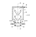
図1に示す鞍乗り型電動車両1は、車体中央前側に走行用のバッテリ(駆動用バッテリ)2を搭載すると共に、車体中央後側には走行用のモータユニット3を搭載し、バッテリ2からの電力によりモータユニット(駆動用モータユニット)3を駆動させると共に、その駆動力を駆動輪たる後輪4に伝達して走行する。
A saddle-ride type electric vehicle 1 shown in FIG. 1 has a traveling battery (drive battery) 2 mounted on the front side of the vehicle body and a traveling
鞍乗り型電動車両1は自動二輪車の態様をなし、その前輪5は左右一対のフロントフォーク6の下端部に軸支され、左右フロントフォーク6の上部はステアリングステム7を介して車体フレーム11前端のヘッドパイプ12に操向可能に枢支される。ステアリングステム7の上部には操向ハンドル8が取り付けられる。
The saddle-ride type electric vehicle 1 is in the form of a motorcycle, the front wheel 5 of which is pivotally supported by the lower ends of a pair of left and
ヘッドパイプ12からは、単一のメインフレーム13が車体左右中央を後下がりに後方に延出する。メインフレーム13の後部下側には、モータユニット3の上端部が固定的に支持されると共に、スイングアーム(リヤスイングアーム)14の前端部が上下揺動可能に支持される。スイングアーム14の後端部には後輪4が軸支される。
From the
図2,3に示すように、メインフレーム13の後部下側には、前後モータ支持ブラケット15,16がそれぞれ左右一対に設けられる。これら左右の前後モータ支持ブラケット15,16間にモータユニット3の上端部が入り込み、これらがボルト締結等により結合されることで、メインフレーム13の後部下側にモータユニット3の上端部が固定的に支持される。
As shown in FIGS. 2 and 3, front and rear
本発明によれば、従来の駆動用モータユニットの支持位置を駆動用バッテリの搭載スペースとして利用した場合でも、ピボット位置を後方にずらすことなく駆動用モータユニットを後方移動させることができる。すなわち、バッテリ積載スペースを多く確保した上で駆動用モータユニットを効率よく配置することができる。
本発明によれば、駆動用モータユニットをできるだけ後方に配置することで、バッテリ搭載スペースのさらなる拡大を図ることができる。
本発明によれば、駆動用モータユニットの前後幅及び上下幅の増大を抑えて駆動用モータユニットの配置自由度を高めると共に、バッテリ搭載スペースのさらなる拡大を図ることができる。
本発明によれば、従動部の配置スペースを前後に広げることができる。
According to the present invention , even when the support position of the conventional drive motor unit is used as a drive battery mounting space, the drive motor unit can be moved backward without shifting the pivot position backward. That is, it is possible to efficiently arrange the drive motor unit while securing a large battery loading space.
According to the present invention , the battery mounting space can be further expanded by arranging the drive motor unit as far back as possible.
ADVANTAGE OF THE INVENTION According to this invention , while suppressing the increase in the front-back width and vertical width of a drive motor unit, the freedom degree of arrangement | positioning of a drive motor unit can be raised, and the further expansion of a battery mounting space can be aimed at.
According to the present invention , the arrangement space of the driven portion can be expanded forward and backward.
図1に示すように、メインフレーム13の前端部下側からは、下方に向けてダウンフレーム21が延出する。ダウンフレーム21は、車体下部にて後方に湾曲して延び、その後端部が連結ブラケット22を介してモータユニット3の下端部前側に連結される。以下、ダウンフレーム21におけるメインフレーム13の前端部下側から下方に延びる部位を下方延出部21a、車体下部にて後方に延びる部位を後方延出部21bという。
As shown in FIG. 1, a
メインフレーム13の後部からはシートフレーム18が後上がりに後方に延びる。シートフレーム18上には乗員着座用のシート18aが支持される。シートフレーム18とスイングアーム14の後端部との間にはクッションユニット19が介設される。自動二輪車1の車体は車体カバー9により適宜覆われる。
A
メインフレーム13の前部の直ぐ下方であってダウンフレーム21の下方延出部21aの直ぐ後方には、前記バッテリ2が搭載される。
バッテリ2は、例えば上下に並ぶ複数の単バッテリを直列に結線して所定の高電圧(48〜72V)を発生するもので、側面視で下方延出部21aに沿って起立する直方体形状のバッテリケース23内に収容される。バッテリ2及びバッテリケース23は、一体のバッテリユニット2Aとして取り扱われる。下方延出部21a及びバッテリケース23は、側面視で長手方向が鉛直方向に対してやや前傾した傾斜姿勢で配置される。なお、前記単バッテリは適宜充放電可能なエネルギーストレージであり、例えばリチウムイオンバッテリ、ニッケル水素バッテリ、鉛バッテリ等からなる。
The
The
バッテリ2(バッテリケース23)の前部の上下には、ダウンフレーム21の下方延出部21aに対してボルト締結等により連結される上下連結部24,25がそれぞれ一体形成される。バッテリ2(バッテリケース23)の下端部後側には、ダウンフレーム21の後方延出部21bの後端部に対してボルト締結等により連結される下突出部(冷却風導入部)27が一体形成される。これら上下連結部24,25及び下方突出部27を介して、バッテリ2が車体フレーム11及びモータユニット3に固定的かつ着脱可能に支持される。
Upper and lower connecting
下突出部27は、バッテリケース23の内部空間に連通する中空状をなし(図8参照)、その左右側部にダウンフレーム21の後方延出部21bの左右後端部がそれぞれボルト締結等により連結される。後方延出部21bの後端部には、前記連結ブラケット22の前端部が溶接又は下突出部27との共締めにより一体に連結される。これにより、バッテリケース23(バッテリ2)の下端部がダウンフレーム21及びモータユニット3に固定的かつ着脱可能に支持される。
The lower projecting
図2,4に示すように、モータユニット3は、その後部に左右方向に沿う回転中心軸線(駆動軸線)C1を有するモータ本体3a及びその従動部である減速機構28を左右に隣接させて配置すると共に、その前部にはモータドライバたるPDU(power driver unit)及びこれを制御するECU(electric control unit)を一体化した制御ユニット29を配置し、かつこの制御ユニット29の直下にはコンタクタ29aを配置し、これらを単一のケーシング31内に収容した構成を有する。なお、図2中符号29bはバッテリ2からコンタクタ29aに至るバッテリ出力ケーブルを示す。前記各モータ支持ブラケット15,16及び連結ブラケット22はケーシング31に連結されている。
As shown in FIGS. 2 and 4, the
モータ本体3aの回転駆動力は、平行軸歯車機構たる前記減速機構28を介してその出力軸(モータユニット3の外部出力部でもある)28aに出力され、さらに例えばチェーン式伝動機構4aを介して後輪4に伝達される。なお、モータ本体3aは例えばVVVF(variable voltage variable frequency)制御が行われるが、手動又は自動の変速機やクラッチを有する構成であってもよい。
The rotational driving force of the
減速機構28は、モータ本体3aの駆動軸3bの先端部に設けられる小径ギヤ28bと、小径ギヤ28bに噛み合う大径ギヤ28cと、大径ギヤ28cの右側に隣接する第二小径ギヤ28dと、第二小径ギヤ28dに噛み合う第二大径ギヤ28eとを有する。第二大径ギヤ28eの左方には出力軸28aが突出する。大径ギヤ28c及び第二小径ギヤ28dを支持するアイドル軸28fは、駆動軸3b及び出力軸28aに対して前方にオフセットして配置される。これにより、減速機構28の高さを抑えつつ減速比を稼ぐことができる。
The
図3を併せて参照し、モータ本体3aは、車体左右中心CLに対して右側にオフセットして配置される。このモータ本体3aの右側部を収容するべく、ケーシング31下部の後部右側には、右方に張り出す有底円筒状のモータ収容部31aが形成される。ケーシング31は、車体左右中心CLを跨ぐ左側部31bと、モータ収容部31aを形成する右側部31cと、減速機構28を収容するギヤケース31dとに分割構成される。
Referring also to FIG. 3, the
図2,5,6に示すように、制御ユニット29は、その外ケース29cの前面をモータユニット3のケーシング31の前面から前方に露出させる。外ケース29cの前面には、上下に延びる放熱フィン29dが複数形成される。放熱フィン29dには、例えば車体カバー9に設けた走行風取り入れ口9aからカバー内に取り入れた走行風が供給される。これにより、後述するバッテリケース23の排風口35からの温風により制御ユニット等の冷却性が阻害されることが抑制される。
As shown in FIGS. 2, 5, and 6, the
また、排風口35から排出される空気は、走行風取り入れ口9aから取り入れた走行風が制御ユニット29の放熱フィン29dに沿って下方に流れることにより引っ張られ、バッテリケース23内の空気の走行風(冷却風)の流量を多くする。
なお、図6中符号29eは制御ユニット29からモータ本体3aに至る三相のモータケーブルを、符号29fはモータケーブル29eを挿通するべくケーシング31に装着されるグロメットをそれぞれ示す。
In addition, the air discharged from the
In FIG. 6,
ここで、図2に示すように、モータ本体3aは、その上端t1がピボット17aよりも下方に位置するように(すなわち、モータ本体3a全体がピボット17aよりも下方に位置するように)配置される。これにより、ピボット17aの後方移動を抑えながらも、モータ本体3aを可及的に後方移動できる。
Here, as shown in FIG. 2, the
図2において、モータ本体3aは、その後部がピボット17aよりも後方に位置するように(さらには、駆動軸線C1がピボット17aよりも後方に位置するように)配置される。なお、図2ではモータ本体3aの前端t2がピボット17aよりも前方に位置しているが、この前端t2がピボット17aよりも後方に位置する(モータ本体3aの全体がピボット17aよりも後方に位置する)構成としてもよい。
In FIG. 2, the
このように、ピボット17aの後方移動を抑えてスイングアーム14長や軸距への影響を抑えながらも、モータ本体3aを可及的に後方に配置してバッテリ搭載スペースの拡大に寄与できる。また、比較的重量のあるモータ本体3aを下方に配置することで、鞍乗り型電動車両1の低重心化にも寄与できる。さらに、モータ本体3aとその従動部たる減速機構28とを左右方向で隣接させることで、モータ本体3a周辺の前後幅及び上下幅の拡大を抑えてピボット17aの配置自由度を向上できる。
Thus, while suppressing the rearward movement of the
また、モータユニット3の出力軸28aは、上下方向でピボット17aとモータ本体3aの駆動軸3bとの間に位置するように配置される。出力軸28aのケーシング31からの突出部分(左端部)には、前記チェーン式伝動機構4aのドライブスプロケット4bが一体回転可能に取り付けられる(図3,4参照)。これにより、ドライブスプロケット4bがピボット17aの近傍に配置されることとなる。
The
図7,8に示すように、ダウンフレーム21は、バッテリケース23内にバッテリ冷却用の走行風を導入するための走行風導入ダクトとしても機能する。
図9を併せて参照し、ダウンフレーム21は、例えば左右一対のダウンチューブ32で構成される。左右ダウンチューブ32は、それぞれ円形鋼管を所望形状に屈曲形成してなり、その上端部が前方に屈曲して車両前方に開口すると共に、後端部が左右方向内側に屈曲してバッテリケース23の下突出部27の左右両側にそれぞれ結合される。これら左右ダウンチューブ32の上端開口が走行風導入口32aとなり、左右ダウンチューブ32の後端開口が走行風排出口32bとなる。
As shown in FIGS. 7 and 8, the
Referring also to FIG. 9, the
ダウンフレーム21の上端部には支持ブラケット33が固設され、この支持ブラケット33がメインフレーム13の前端部下側にボルト締結等により着脱可能に固定される(図1参照)。一方、ダウンフレーム21の後端部は、前述の如くバッテリケース23の下突出部27にボルト締結等により着脱可能に固定される。なお、図中符号34は左右ダウンチューブ32の後端部内側端に固設された固定フランジを示す。
A
バッテリケース23内には、バッテリ2が所定の間隙を有して収容される。そして、ダウンフレーム21を通じて下突出部27からバッテリケース23内に導入された走行風は、バッテリ2から熱を奪いつつ上昇気流となってバッテリケース23内を上昇し、バッテリケース23の上端部の例えば後部一側に形成された排風口35よりケース外部に排出される。なお、バッテリケース23内には、バッテリ2の充放電状況や温度等を監視する不図示のBMU(battery managing unit)も収容されて、バッテリ2と一体的に取り扱われる。
The
以上説明したように、上記実施形態における鞍乗り型電動車両1は、車体フレーム11のメインフレーム13の直ぐ下方に駆動用バッテリ2を積載すると共に、モータユニット3を前記車体フレーム11に固定的に支持するものであって、前記モータユニット3が、スイングアーム14のピボット17aよりも下方に配置されるものである。
この構成によれば、従来のモータユニット3の支持位置を駆動用バッテリ2の搭載スペースとして利用した場合でも、ピボット位置を後方にずらすことなくモータユニット3を後方移動させることができる。すなわち、バッテリ積載スペースを多く確保した上でモータユニット3を効率よく配置することができる。
As described above, the saddle-ride type electric vehicle 1 in the above-described embodiment has the driving
According to this configuration, even when the support position of the
また、上記鞍乗り型電動車両1は、前記モータユニット3の少なくとも一部が前記ピボット17aよりも後方に配置されるか、前記モータユニット3の駆動軸線C1が前記ピボット17aよりも後方に配置されるか、前記モータユニット3の全体が前記ピボット17aよりも後方に配置されるものである。
この構成によれば、モータユニット3をできるだけ後方に配置することで、バッテリ搭載スペースのさらなる拡大を図ることができる。
Further, in the saddle-ride type electric vehicle 1, at least a part of the
According to this configuration, the battery mounting space can be further expanded by arranging the
また、上記鞍乗り型電動車両1は、前記モータユニット3が、左右方向に沿う駆動軸線C1を有するモータ本体3aと、前記モータ本体3aの駆動力を受けて作動する従動部(減速機構28)とを有し、前記モータ本体3aが、車体左右中心CLに対して左右方向一側に偏倚して配置され、このモータ本体3aの左右方向他側に、前記従動部が配置されるものである。
この構成によれば、モータユニット3の前後幅及び上下幅の増大を抑えてモータユニット3の配置自由度を高めると共に、バッテリ搭載スペースのさらなる拡大を図ることができる。
Further, in the saddle-ride type electric vehicle 1, the
According to this configuration, it is possible to suppress the increase in the front-rear width and the vertical width of the
なお、本発明は上記実施形態に限られるものではなく、例えば、前記鞍乗り型電動車両には、車体を跨いで乗車する車両全般が含まれ、自動二輪車のみならず、三輪(前一輪かつ後二輪の他に、前二輪かつ後一輪の車両も含む)又は四輪の車両も含まれる。
そして、上記実施形態における構成は本発明の一例であり、当該発明の要旨を逸脱しない範囲で種々の変更が可能であることはいうまでもない。
The present invention is not limited to the above-described embodiment. For example, the saddle-ride type electric vehicle includes all vehicles that straddle the vehicle body, and includes not only motorcycles but also three-wheels (front and rear wheels). In addition to a two-wheel vehicle, a front two-wheel vehicle and a single rear wheel vehicle are also included.
And the structure in the said embodiment is an example of this invention, and it cannot be overemphasized that a various change is possible in the range which does not deviate from the summary of the said invention.
1 鞍乗り型電動車両
2 駆動用バッテリ
3 モータユニット(駆動用モータユニット)
3a モータ本体
3b 駆動軸
C1 駆動軸線
11 車体フレーム
13 メインフレーム
14 スイングアーム(リヤスイングアーム)
17a ピボット
28 減速機構(従動部)
28a 出力軸
CL 車体左右中心
1 Saddle-ride type
28a Output shaft CL Body left / right center
Claims (13)
前記駆動用モータユニット(3)のモータ本体(3a)が、リヤスイングアーム(14)のピボット(17a)よりも下方に配置されると共に、前記モータ本体(3a)の少なくとも一部が、前記ピボット(17a)よりも後方に配置され、
前記メインフレーム(13)には前記駆動用モータユニット(3)を支持する前後モータ支持ブラケット(15,16)が設けられ、前記モータ本体(3a)の駆動軸線(C1)が前記前後モータ支持ブラケット(15,16)の間に配置されることを特徴とする鞍乗り型電動車両。 A saddle-ride type electric motor in which a driving battery (2) is loaded immediately below a main frame (13) of a vehicle body frame (11), and a driving motor unit (3) is fixedly supported on the vehicle body frame (11). Vehicle (1),
A motor body (3a) of the drive motor unit (3) is disposed below the pivot (17a) of the rear swing arm (14), and at least a part of the motor body (3a) (17a) is arranged behind ,
The main frame (13) is provided with front and rear motor support brackets (15, 16) for supporting the drive motor unit (3), and the drive axis (C1) of the motor body (3a) is connected to the front and rear motor support bracket. A straddle-type electric vehicle characterized by being arranged between (15, 16) .
前記ダウンフレーム(21)は、その後端部が前記駆動用モータユニット(3)に連結され、このダウンフレーム(21)に前記駆動用バッテリ(2)が固定されることを特徴とする請求項1から6の何れか一項に記載の鞍乗り型電動車両。 The down frame (21) has a rear end connected to the drive motor unit (3), and the drive battery (2) is fixed to the down frame (21). The saddle-ride type electric vehicle according to any one of claims 1 to 6.
前記ダウンフレーム(21)が、このダウンフレーム(21)内に走行風を導入可能とする走行風導入口(32a)と、前記ダウンフレーム(21)内に導入した走行風を排出可能とする走行風排出口(32b)とを有し、 The down frame (21) travels to allow the travel wind to be introduced into the down frame (21), and to allow the travel wind introduced into the down frame (21) to be discharged. A wind outlet (32b),
前記駆動用バッテリ(2)が、冷却風導入部(27)を有するバッテリケース(23)内に収容され、前記走行風排出口(32b)が前記冷却風導入部(27)に接続されることを特徴とする請求項1から7の何れか一項に記載の鞍乗り型電動車両。 The drive battery (2) is accommodated in a battery case (23) having a cooling air introduction part (27), and the traveling air discharge port (32b) is connected to the cooling air introduction part (27). The saddle-ride type electric vehicle according to any one of claims 1 to 7.
Priority Applications (3)
| Application Number | Priority Date | Filing Date | Title |
|---|---|---|---|
| JP2010251780A JP5542626B2 (en) | 2010-11-10 | 2010-11-10 | Saddle riding type electric vehicle |
| US13/290,266 US8783405B2 (en) | 2010-11-10 | 2011-11-07 | Saddle-type electric vehicle |
| CN201110353104.7A CN102463883B (en) | 2010-11-10 | 2011-11-07 | Saddle-ride type electric vehicle |
Applications Claiming Priority (1)
| Application Number | Priority Date | Filing Date | Title |
|---|---|---|---|
| JP2010251780A JP5542626B2 (en) | 2010-11-10 | 2010-11-10 | Saddle riding type electric vehicle |
Publications (2)
| Publication Number | Publication Date |
|---|---|
| JP2012101679A JP2012101679A (en) | 2012-05-31 |
| JP5542626B2 true JP5542626B2 (en) | 2014-07-09 |
Family
ID=46018554
Family Applications (1)
| Application Number | Title | Priority Date | Filing Date |
|---|---|---|---|
| JP2010251780A Active JP5542626B2 (en) | 2010-11-10 | 2010-11-10 | Saddle riding type electric vehicle |
Country Status (3)
| Country | Link |
|---|---|
| US (1) | US8783405B2 (en) |
| JP (1) | JP5542626B2 (en) |
| CN (1) | CN102463883B (en) |
Families Citing this family (51)
| Publication number | Priority date | Publication date | Assignee | Title |
|---|---|---|---|---|
| JP5595227B2 (en) * | 2010-10-29 | 2014-09-24 | 本田技研工業株式会社 | Electric motorcycle |
| JP2012096613A (en) * | 2010-10-29 | 2012-05-24 | Honda Motor Co Ltd | Electric vehicle |
| WO2012066598A1 (en) * | 2010-11-18 | 2012-05-24 | 川崎重工業株式会社 | Electric two-wheeled vehicle |
| WO2012066599A1 (en) * | 2010-11-18 | 2012-05-24 | 川崎重工業株式会社 | Electric two-wheeled vehicle |
| US9027694B2 (en) * | 2010-11-18 | 2015-05-12 | Kawasaki Jukogyo Kabushiki Kaisha | Saddle-type electric vehicle |
| JP5695471B2 (en) | 2011-03-31 | 2015-04-08 | 本田技研工業株式会社 | Electric vehicle |
| US9205757B2 (en) * | 2011-10-28 | 2015-12-08 | Kawasaki Jukogyo Kabushiki Kaisha | Straddle electric vehicle |
| US9278725B2 (en) * | 2011-12-28 | 2016-03-08 | Kawasaki Jukogyo Kabushiki Kaisha | Straddle electric vehicle |
| US9643514B2 (en) * | 2011-12-28 | 2017-05-09 | Kawasaki Jukogyo Kabushiki Kaisha | Straddle electric vehicle |
| CN103946108B (en) * | 2011-12-28 | 2016-08-24 | 川崎重工业株式会社 | Saddle-type electric vehicle |
| WO2014054069A1 (en) * | 2012-10-03 | 2014-04-10 | 川崎重工業株式会社 | Electric vehicle, and battery pack |
| JP6056348B2 (en) * | 2012-10-09 | 2017-01-11 | スズキ株式会社 | Fuel cell motorcycle |
| US10011323B2 (en) * | 2012-12-25 | 2018-07-03 | Kawasaki Jukogyo Kabushiki Kaisha | Electric vehicle |
| JP6088839B2 (en) * | 2013-02-14 | 2017-03-01 | 本田技研工業株式会社 | Saddle riding vehicle |
| JP6232941B2 (en) * | 2013-11-05 | 2017-11-22 | スズキ株式会社 | Electric motor support structure |
| US9340254B2 (en) * | 2014-04-15 | 2016-05-17 | Brammo, Inc. | Electric motorcycle with adjustable squat ratio isolated from vehicle geometry |
| US10023264B2 (en) * | 2015-04-02 | 2018-07-17 | GM Global Technology Operations LLC | Cooling method for E-bike power and energy systems |
| JP6145146B2 (en) * | 2015-09-28 | 2017-06-07 | ヤマハ発動機株式会社 | Straddle-type electric vehicle |
| KR101670201B1 (en) * | 2016-01-28 | 2016-10-27 | 백상기 | A bicycle which has sub frame to fix a battery pack |
| JP6706952B2 (en) * | 2016-03-31 | 2020-06-10 | 本田技研工業株式会社 | Saddle type vehicle |
| JP6675249B2 (en) * | 2016-03-31 | 2020-04-01 | 本田技研工業株式会社 | Saddle type vehicle |
| JP6671219B2 (en) * | 2016-03-31 | 2020-03-25 | 本田技研工業株式会社 | Saddle-type electric vehicle |
| US10711737B2 (en) * | 2017-08-11 | 2020-07-14 | Honda Motor Co., Ltd. | Conduit mounting device |
| DE112018005028T5 (en) * | 2017-09-11 | 2020-07-02 | Honda Motor Co., Ltd. | Electric motorcycle |
| JP6843259B2 (en) * | 2017-09-29 | 2021-03-17 | 本田技研工業株式会社 | Saddle-type electric vehicle |
| JP6369614B1 (en) * | 2017-09-29 | 2018-08-08 | トヨタ自動車株式会社 | Vehicle casing |
| WO2019165155A1 (en) * | 2018-02-24 | 2019-08-29 | Eich Ernest Paul Iv | Straddle-ridden vehicle frame stiffener |
| JP6979120B2 (en) * | 2018-03-29 | 2021-12-08 | 本田技研工業株式会社 | Saddle-type electric vehicle |
| WO2019186947A1 (en) * | 2018-03-29 | 2019-10-03 | 本田技研工業株式会社 | Saddle riding-type electric vehicle |
| JP7096879B2 (en) * | 2018-03-29 | 2022-07-06 | 本田技研工業株式会社 | Saddle-type electric vehicle |
| CN111902339B (en) * | 2018-03-29 | 2022-07-26 | 本田技研工业株式会社 | Saddle-ride type electric vehicle |
| CN111836756B (en) * | 2018-03-29 | 2022-04-29 | 本田技研工业株式会社 | Saddle-ride type electric vehicle |
| WO2019186953A1 (en) | 2018-03-29 | 2019-10-03 | 本田技研工業株式会社 | Saddle riding-type electric vehicle |
| JP6971381B2 (en) * | 2018-03-29 | 2021-11-24 | 本田技研工業株式会社 | Saddle-type electric vehicle |
| WO2019186954A1 (en) * | 2018-03-29 | 2019-10-03 | 本田技研工業株式会社 | Saddle riding-type electric vehicle |
| US11654996B2 (en) * | 2018-04-27 | 2023-05-23 | FUELL Inc. | Electric saddle type vehicle |
| US11753101B2 (en) | 2018-04-27 | 2023-09-12 | FUELL Inc. | Electric saddle type vehicle with storage areas |
| JP6749979B2 (en) * | 2018-09-27 | 2020-09-02 | 本田技研工業株式会社 | Saddle-type electric vehicle |
| JP7149161B2 (en) | 2018-10-30 | 2022-10-06 | 本田技研工業株式会社 | saddle type electric vehicle |
| JP7200653B2 (en) * | 2018-12-18 | 2023-01-10 | スズキ株式会社 | Electric straddle-type vehicle |
| JP7200654B2 (en) * | 2018-12-18 | 2023-01-10 | スズキ株式会社 | Electric straddle-type vehicle |
| JP7165757B2 (en) * | 2019-02-05 | 2022-11-04 | 本田技研工業株式会社 | Electric vehicle and battery unit |
| CN216232808U (en) * | 2019-03-19 | 2022-04-08 | 本田技研工业株式会社 | Series hybrid two-wheel motorcycle |
| WO2020213162A1 (en) * | 2019-04-19 | 2020-10-22 | ヤマハ発動機株式会社 | Straddled vehicle |
| CN113840775A (en) * | 2019-05-27 | 2021-12-24 | Tvs电机股份有限公司 | Drive system for saddle type vehicle |
| IT201900020398A1 (en) * | 2019-11-05 | 2021-05-05 | Efesto S A R L | HYBRID DRIVE MOTORCYCLE AND HYBRIDIZATION KIT FOR A MOTORCYCLE |
| KR20210058552A (en) * | 2019-11-14 | 2021-05-24 | 현대자동차주식회사 | Inlet duct structure for vehicle battery system |
| JP7437251B2 (en) * | 2020-07-07 | 2024-02-22 | カワサキモータース株式会社 | saddle vehicle |
| JP2022027322A (en) * | 2020-07-31 | 2022-02-10 | 株式会社シマノ | Battery holding device for human power-driven vehicle, drive unit for human power-driven vehicle, and battery unit for human power-driven vehicle |
| TWI778458B (en) * | 2020-11-26 | 2022-09-21 | 光陽工業股份有限公司 | electric locomotive |
| JP2024015970A (en) * | 2022-07-25 | 2024-02-06 | カワサキモータース株式会社 | Straddle electric vehicle |
Family Cites Families (12)
| Publication number | Priority date | Publication date | Assignee | Title |
|---|---|---|---|---|
| US3991843A (en) * | 1974-06-28 | 1976-11-16 | The Lucas Electrical Company Limited | Cycles |
| US4280581A (en) * | 1978-05-12 | 1981-07-28 | Rudwick Lawrence A | Motor and pedal driven bicycles |
| JP3317560B2 (en) * | 1993-10-19 | 2002-08-26 | 本田技研工業株式会社 | Battery cooling structure for electric vehicles |
| JP4037952B2 (en) * | 1998-03-16 | 2008-01-23 | ヤマハ発動機株式会社 | Electric motorcycle |
| JP3194472B2 (en) | 1999-07-16 | 2001-07-30 | 本田技研工業株式会社 | Motorcycle drive unit with electric motor |
| JP3942773B2 (en) * | 1999-10-14 | 2007-07-11 | ヤマハ発動機株式会社 | Series hybrid electric motorcycle |
| JP3998118B2 (en) * | 2000-10-10 | 2007-10-24 | 本田技研工業株式会社 | Electric vehicle |
| US20020108798A1 (en) * | 2001-02-09 | 2002-08-15 | Huntsberger Kurt J. | Scooter |
| JP4086220B2 (en) * | 2001-06-26 | 2008-05-14 | 本田技研工業株式会社 | Electric vehicle |
| JP4377561B2 (en) * | 2001-12-20 | 2009-12-02 | 本田技研工業株式会社 | Electric vehicle power unit structure |
| US7210550B2 (en) * | 2003-05-30 | 2007-05-01 | Honda Motor Co., Ltd. | Under-seat structure for a motorcycle |
| US9027694B2 (en) * | 2010-11-18 | 2015-05-12 | Kawasaki Jukogyo Kabushiki Kaisha | Saddle-type electric vehicle |
-
2010
- 2010-11-10 JP JP2010251780A patent/JP5542626B2/en active Active
-
2011
- 2011-11-07 CN CN201110353104.7A patent/CN102463883B/en active Active
- 2011-11-07 US US13/290,266 patent/US8783405B2/en not_active Expired - Fee Related
Also Published As
| Publication number | Publication date |
|---|---|
| JP2012101679A (en) | 2012-05-31 |
| US8783405B2 (en) | 2014-07-22 |
| US20120111651A1 (en) | 2012-05-10 |
| CN102463883B (en) | 2016-03-09 |
| CN102463883A (en) | 2012-05-23 |
Similar Documents
| Publication | Publication Date | Title |
|---|---|---|
| JP5542626B2 (en) | Saddle riding type electric vehicle | |
| JP4353415B2 (en) | Electric vehicle | |
| EP2799321B1 (en) | Saddle-type electric vehicle | |
| JP6304197B2 (en) | Electric motorcycle | |
| JP2010018270A (en) | Electric vehicle equipped with rider saddle | |
| CN111377017B (en) | Saddle-ride type electric vehicle | |
| JP2003312571A (en) | Body frame for scooter type motorcycle | |
| CN107685826B (en) | Rocker arm structure of saddle-type electric vehicle | |
| JP2018052353A (en) | Fuel cell stack fixing structure of saddle-riding type electric vehicle | |
| TWI266708B (en) | Battery holding device for electric vehicle | |
| JP2013136310A (en) | Vehicle body structure of straddle-type electric vehicle | |
| JP5794785B2 (en) | Saddle riding vehicle | |
| CN113365907B (en) | Saddle-ride type electric vehicle | |
| JP4986684B2 (en) | Saddle riding four-wheeled vehicle | |
| JP2012101678A (en) | Saddle-riding type electric vehicle | |
| JP2012086689A (en) | Saddle riding type electric vehicle | |
| CN110997471A (en) | Support structure for two-wheeled vehicle | |
| EP2088068B1 (en) | Motorcycle | |
| JP7213178B2 (en) | straddled vehicle | |
| CN109789907B (en) | Motor cooling structure for saddle-ride type electric vehicle | |
| JP2013129338A (en) | Power unit for saddle riding type electric vehicle and saddle riding type electric vehicle | |
| JP7292432B2 (en) | saddle type electric vehicle | |
| CN112770964B (en) | Saddle-ride type electric vehicle | |
| JP2012101567A (en) | Saddle-riding type electric vehicle | |
| JP6849727B2 (en) | Saddle-type vehicle |
Legal Events
| Date | Code | Title | Description |
|---|---|---|---|
| A621 | Written request for application examination |
Free format text: JAPANESE INTERMEDIATE CODE: A621 Effective date: 20121127 |
|
| A131 | Notification of reasons for refusal |
Free format text: JAPANESE INTERMEDIATE CODE: A131 Effective date: 20140114 |
|
| A977 | Report on retrieval |
Free format text: JAPANESE INTERMEDIATE CODE: A971007 Effective date: 20140116 |
|
| A521 | Written amendment |
Free format text: JAPANESE INTERMEDIATE CODE: A523 Effective date: 20140311 |
|
| TRDD | Decision of grant or rejection written | ||
| A01 | Written decision to grant a patent or to grant a registration (utility model) |
Free format text: JAPANESE INTERMEDIATE CODE: A01 Effective date: 20140408 |
|
| A61 | First payment of annual fees (during grant procedure) |
Free format text: JAPANESE INTERMEDIATE CODE: A61 Effective date: 20140507 |
|
| R150 | Certificate of patent or registration of utility model |
Ref document number: 5542626 Country of ref document: JP Free format text: JAPANESE INTERMEDIATE CODE: R150 |