JP2012127471A5 - - Google Patents
Download PDFInfo
- Publication number
- JP2012127471A5 JP2012127471A5 JP2010281737A JP2010281737A JP2012127471A5 JP 2012127471 A5 JP2012127471 A5 JP 2012127471A5 JP 2010281737 A JP2010281737 A JP 2010281737A JP 2010281737 A JP2010281737 A JP 2010281737A JP 2012127471 A5 JP2012127471 A5 JP 2012127471A5
- Authority
- JP
- Japan
- Prior art keywords
- shift
- clutch ring
- meshing
- gear
- transmission
- Prior art date
- Legal status (The legal status is an assumption and is not a legal conclusion. Google has not performed a legal analysis and makes no representation as to the accuracy of the status listed.)
- Granted
Links
Images
Description
本発明は、自動車、建機、農業車両等の変速を行わせるトランスミッションに関する。 The present invention relates to a transmission for shifting a vehicle, a construction machine, an agricultural vehicle, or the like.
一般に、シングル・クラッチを使用した車両用のトランスミッションは、変速時に駆動力が途切れ、変速ショックや加速遅れ等が避けられなかった。また大きな走行抵抗を有し、速度エネルギーが小さい建機、農機等にあっては変速時、駆動力が途切れると即停止してしまい変速が困難な場合も生じる。 In general, in a vehicle transmission using a single clutch, the driving force is interrupted at the time of a shift, and a shift shock or an acceleration delay cannot be avoided. In addition, in a construction machine or agricultural machine having a large running resistance and a small speed energy, when the driving force is interrupted at the time of shifting, it may stop immediately and the shifting may be difficult.
これに対し、ツイン・クラッチのトランスミッションは、駆動力が途切れず、変速ショックや加速遅れを抑制できるものとして知られている。 On the other hand, the transmission of the twin clutch is known as a driving force that is not interrupted and can suppress shift shock and acceleration delay.
しかし、ツイン・クラッチのトランスミッションは、構造が複雑で重量が大きいという問題がある。 However, the twin clutch transmission has a problem that its structure is complicated and heavy.
一方、シームレスシフト・トランスミッションの中には、重量増を抑制できるものとして注目されているものがある。 On the other hand, in the seamless shift transmissions, there is one that is attracting attention as it can suppress the increase in weight.
以下に、この種のシームレスシフト・トランスミッションの動作を説明する。ここでは、説明を簡単にするため、1速、2速間の変速を説明する。 The operation of this type of seamless shift transmission will be described below. Here, in order to simplify the description, a shift between the first speed and the second speed will be described.
このシームレスシフト・トランスミッションでは、1速ギヤ、2速ギヤ間に入力軸に係合した3個の第1ビュレット、3個の第2ビュレットを備え、シフト操作に応じて移動する構成となっている。1速ギヤ及び2速ギヤには、噛合い歯が形成され、第1ビュレット及び第2ビュレットの両端部には、回転方向前後で異なった複雑なフェースが形成されている。 This seamless shift transmission has three first burettes and three second burettes engaged with the input shaft between the first gear and the second gear, and is configured to move according to the shift operation. . The 1st speed gear and the 2nd speed gear are formed with meshing teeth, and different complex faces are formed on both ends of the first and second burettes before and after the rotation direction.
第1ビュレット及び第2ビュレットは、セレクトフォークの動作に対しスプリングを介して1速ギヤ又は2速ギヤ側へ移動する構成である。 The first buret and the second burette are configured to move toward the first gear or the second gear via a spring with respect to the operation of the select fork.
このような構成により、例えば1速ギヤへの変速時は、3個の第1ビュレットが1速ギヤの噛合い歯に噛み合ってから残りの3個の第2ビュレットが噛合い歯に噛み合う。 With such a configuration, for example, when shifting to the first speed gear, the three first burettes mesh with the meshing teeth of the first speed gear, and then the remaining three second burettes mesh with the meshing teeth.
2速への変速時は、3個の第2ビュレットが2速ギヤの噛合い歯に噛み合ってから残りの3個の第1ビュレットが噛合い歯に噛み合う。 At the time of shifting to the second speed, the three second burettes mesh with the meshing teeth of the second speed gear, and then the remaining three first burettes mesh with the meshing teeth.
このような複雑なフェースを備えた第1ビュレット及び第2ビュレットとスプリングを介したセレクト動作とにより、駆動力が途切れず、変速ショックや加速の遅れを抑制し、且つ重量軽減を図ることができる。 With the first and second burettes having such complicated faces and the selection operation via the spring, the driving force is not interrupted, the shift shock and the delay in acceleration can be suppressed, and the weight can be reduced. .
しかし、第1ビュレット及び第2ビュレット等を備えた構造が複雑であり、部品点数も増大するという問題がある。 However, there is a problem that the structure including the first bullet and the second bullet is complicated and the number of parts increases.
解決しようとする問題点は、駆動力が途切れず、変速ショックや加速の遅れを抑制し、且つ重量軽減を図ることはできるが、構造が複雑であった点である。 The problem to be solved is that the driving force is not interrupted, the shift shock and acceleration delay can be suppressed and the weight can be reduced, but the structure is complicated.
本発明は、駆動力が途切れず、変速ショックや加速の遅れを抑制し、重量軽減を図ることができ、且つ構造を簡単にすることを可能とするため、駆動力伝達軸に相対回転可能に支持された複数段の変速ギヤと、前記変速ギヤを前記駆動力伝達軸に選択的に結合して変速出力するために複数備えられ前記変速ギヤに選択的な噛み合いが可能なクラッチ・リングと、このクラッチ・リングを選択的に操作する変速操作部とを備え、前記クラッチ・リングと前記駆動力伝達軸との間に、前記変速操作部のシフト・アップ動作又はシフト・ダウン動作により変速下段及び変速上段のクラッチ・リングが同時噛合いした時に前記変速下段又は変速上段のクラッチ・リングに噛合い解除方向の軸力を生じさせるガイド部を備えたことを特徴とする。 In the present invention, the driving force is not interrupted, the shift shock and the delay in acceleration can be suppressed, the weight can be reduced, and the structure can be simplified. A plurality of supported transmission gears, and a plurality of clutch rings provided to selectively couple the transmission gears to the driving force transmission shaft and to output a shift, and capable of being selectively engaged with the transmission gears; and a shift operating unit for operating the clutch ring selectively, between said clutch ring driving force transmitting shaft, shifting the lower and the shift-up operation or shift-down operation of the gearshift operating part shifting the upper clutch ring characterized by comprising a guide unit to generate the axial force of the transmission lower or meshing the gear upper clutch ring releasing direction when had simultaneously engaged.
本発明は、上記手段としたため、駆動力が途切れず、変速ショックや加速の遅れを抑制し、且つ重量軽減を図ることができ、且つ構造を簡単にすることができる。 Since the present invention is the above-described means, the driving force is not interrupted, the shift shock and the delay in acceleration can be suppressed, the weight can be reduced, and the structure can be simplified.
駆動力が途切れず、変速ショックや加速の遅れを抑制し、重量軽減を図ることができ、且つ構造を簡単にするという目的を、変速操作部のシフト・アップ動作又はシフト・ダウン動作により変速下段及び変速上段のクラッチ・リングが同時噛合いした時に変速下段又は変速上段のクラッチ・リングに噛合い解除方向の軸力を生じさせるガイド部を備えたことにより実現した。 Driving force is not interrupted, and suppress shift shock or acceleration delay, it is possible to achieve reduction in weight, and the object of simplifying the structure, shifting the lower the shift-up operation or shift-down operation of the gearshift operating part and shifting the upper clutch ring is achieved by having a guide portion to cause axial force transmission lower or meshing the gear upper clutch ring releasing direction when had simultaneously engaged.
前記クラッチ・リングは、変速ギヤに対し軸方向の第1の噛合い位置で噛合う状態と前記第1の噛合い位置よりも噛合いを浅くする第2の噛み合い位置で噛合う状態とに移動可能であり、前記クラッチ・リングが変速下段及び変速上段で同時噛合いした時に前記変速下段又は変速上段のクラッチ・リングを、前記第2の噛み合い位置にする機構を備え、前記クラッチ・リングと前記駆動力伝達軸との間に、前記変速操作部のシフト・アップ動作又はシフト・ダウン動作により変速下段及び変速上段のクラッチ・リングが同時噛合いした時に前記変速下段又は変速上段のクラッチ・リングに前記第2の噛み合い位置でコースティング・トルクにより噛合い解除方向の軸力を生じさせるガイド部を備える構成でもよい。 The clutch ring moves to a state in which it engages with the transmission gear at the first meshing position in the axial direction and a state in which the clutch ring engages at a second meshing position that is shallower than the first meshing position. A mechanism for bringing the clutch ring of the lower gear stage or the upper gear stage into the second meshing position when the clutch ring is simultaneously engaged at the lower gear stage and the upper gear stage. When the lower shift gear and upper shift clutch ring are meshed simultaneously with the driving force transmission shaft by the shift up / down operation of the shift operation section, the lower shift gear or the upper shift clutch ring A configuration may be provided that includes a guide portion that generates an axial force in the meshing release direction by a coasting torque at the second meshing position .
図1は、本発明実施例1のトランスミッションをフロント・デファレンシャル装置と共に示す概略断面図、図2は、トランスミッションの要部拡大断面図である。 FIG. 1 is a schematic cross-sectional view showing a transmission according to Embodiment 1 of the present invention together with a front differential device, and FIG. 2 is an enlarged cross-sectional view of a main part of the transmission.
図1、図2のように、トランスミッション1は、駆動力伝達軸としてメイン・シャフト3及びカウンター・シャフト5、アイドラー・シャフト7を備えている。これらメーン・メイン・シャフト3及びカウンター・シャフト5は、軸受9,11,13,15等によりミッションケース17に回転自在に支持されている。アイドラー・シャフト7は、ミッションケース17側に固定されている。 As shown in FIGS. 1 and 2, the transmission 1 includes a main shaft 3, a counter shaft 5, and an idler shaft 7 as driving force transmission shafts. The main main shaft 3 and the counter shaft 5 are rotatably supported on the transmission case 17 by bearings 9, 11, 13, 15 and the like. The idler shaft 7 is fixed to the mission case 17 side.
メーン・メイン・シャフト3とカウンター・シャフト5とには、複数段の変速ギヤとして1速ギヤ19、2速ギヤ21、3速ギヤ23、4速ギヤ25、5速ギヤ27、6速ギヤ29が相対回転可能に支持されている。
The main main shaft 3 and the counter shaft 5 include a first speed gear 19, a second speed gear 21, a third speed gear 23, a fourth speed gear 25, a fifth speed gear 27, and a
カウンター・シャフト5上の1速ギヤ19、3速ギヤ23は、メーン・メイン・シャフト3の出力ギヤ31,33に噛合い、メーン・メイン・シャフト3上の2速ギヤ21、4速ギヤ25、5速ギヤ27、6速ギヤ29は、カウンター・シャフト5の入力ギヤ35,37,39,41にそれぞれ噛合っている。
The first speed gear 19 and the third speed gear 23 on the counter shaft 5 mesh with the output gears 31 and 33 of the main main shaft 3, and the second speed gear 21 and the fourth speed gear 25 on the main main shaft 3. The fifth gear 27 and the
アイドラー・シャフト7上のリバース・アイドラー43は、軸方向移動によりメーン・メイン・シャフト3上の出力ギヤ44及びカウンター・シャフト5上の入力ギヤ45に噛合い可能に配置されている。 The reverse idler 43 on the idler shaft 7 is disposed so as to be able to mesh with the output gear 44 on the main main shaft 3 and the input gear 45 on the counter shaft 5 by axial movement.
1速ギヤ19、3速ギヤ23は、第1の噛合いクラッチ47によりカウンター・シャフト5に選択的に結合され、2速ギヤ21、4速ギヤ25、5速ギヤ27、6速ギヤ29は、第2、第3の噛合いクラッチ49,51によりメイン・シャフト3に選択的に結合される。この選択的な結合によりメイン・シャフト3からカウンター・シャフト5に変速出力可能となっている。
The first speed gear 19 and the third speed gear 23 are selectively coupled to the counter shaft 5 by the first meshing clutch 47, and the second speed gear 21, the fourth speed gear 25, the fifth speed gear 27, and the
第1〜第3の噛合いクラッチ47,49,51は、複数段の変速ギヤの変速上段への変速を、複数の第1〜第3の噛合いクラッチ47,49,51を変更して行なうようになっている。
The first to third meshing
すなわち、複数段の変速ギヤである1速ギヤ19、2速ギヤ21、3速ギヤ23、4速ギヤ25、5速ギヤ27、6速ギヤ29は、第1〜第3の噛合いクラッチ47,49,51を変更して変速を行うように配列されている。
That is, the first speed gear 19, the second speed gear 21, the third speed gear 23, the fourth speed gear 25, the fifth speed gear 27, and the
例えば1速ギヤ19から2速ギヤ21への変速は、複数の第1、第2の噛合いクラッチ47,49を変更して行なう。 For example, the shift from the first gear 19 to the second gear 21 is performed by changing the plurality of first and second meshing clutches 47 and 49.
第1〜第3の噛合いクラッチ47,49,51は、基本的には同一構造であり、クラッチ・カム・リング53,55,57、クラッチ・リング59,61,63、クラッチ・リング59,61,63及び1速ギヤ19〜6速ギヤ29の各対向面に形成されたクラッチ歯47a,47b,49a,49b,51a,51b、19a,21a,23a,25a,27a,29aを備えている。
The first to third meshing
したがって、クラッチ・リング59,61,63は、メーン・メイン・シャフト3、カウンター・シャフト5の軸方向へ噛合い移動してクラッチ歯47a,47b,49a,49b,51a,51b、19a,21a,23a,25a,27a,29aの選択的な噛合いにより変速出力のための結合を行わせる。
Accordingly, the
第1〜第3の噛合いクラッチ47,49,51のクラッチ・カム・リング53,55,57には、への字状のカム溝65,67,69が形成されている。第1の噛合いクラッチ47のクラッチ・カム・リング53は、カウンター・シャフト5に結合され、一体回転可能となっている。第2,第3の噛合いクラッチ49,51のクラッチ・カム・リング55,57は、メーン・メイン・シャフト3に結合され、一体回転可能となっている。
In the clutch cam rings 53, 55, 57 of the first to third meshing
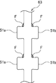
第1〜第3の噛合いクラッチ47,49,51のクラッチ・リング59,61,63は、クラッチ・カム・リング53,55,57の外周に嵌合配置され、軸方向へ移動可能となっている。このクラッチ・リング61,63は、変速ギヤである2速ギヤ21、4速ギヤ25、5速ギヤ27、6速ギヤ29を前記駆動力伝達軸であるメイン・シャフト3に選択的に結合して変速出力するために複数備えら、クラッチ・リング59は、変速ギヤである1速ギヤ19、3速ギヤ23を前記駆動力伝達軸であるカウンター・シャフト5に選択的に結合して変速出力するために複数備えられている。クラッチ・リング59,61,63の内周には、カム突部71,73,75が形成され、カム溝65,67,69に嵌合しガイドされるようになっている。
The
クラッチ・リング59及びリバース・アイドラー43には、後述するシフト・フォーク77,79が嵌合する周凹条81,83が形成されている。クラッチ・リング59の外周には、さらに前記入力ギヤ45が形成されている。クラッチ・リング61,63には、後述するシフト・フォーク85,87が嵌合する周凸条89,91が形成されている。クラッチ・リング59,61,63の両サイドには、1速ギヤ19、2速ギヤ21、3速ギヤ23、4速ギヤ25、5速ギヤ27、6速ギヤ29を選択して各両サイドに2速以上はなして配置し、それぞれ両サイドの変速ギヤに選択的な噛み合いが可能となっている。つまり、クラッチ・リング59の両サイドには1速ギヤ19、3速ギヤ23が配置され、クラッチ・リング61の両サイドには2速ギヤ21、5速ギヤ27が配置され、クラッチ・リング63の両サイドには4速ギヤ25、6速ギヤ29が配置されている。
The clutch ring 59 and the reverse idler 43 are formed with circumferential recesses 81 and 83 into which shift forks 77 and 79 described later are fitted. The input gear 45 is further formed on the outer periphery of the clutch ring 59. The clutch rings 61 and 63 are formed with circumferential ridges 89 and 91 into which shift forks 85 and 87 described later are fitted. On both sides of the clutch rings 59, 61, 63, the first speed gear 19, the second speed gear 21, the third speed gear 23, the fourth speed gear 25, the fifth speed gear 27, and the
第1〜第3の噛合いクラッチ47,49,51は、変速操作部93により選択的に操作されるようになっている。リバース・アイドラー43も、変速操作部93により操作されるようになっている。
The first to
変速操作部93は、ミッションケース17内に備えられ、複数のシフト・フォーク77,79,85,87と複数のシフト・ロッド103,105,107,109とシフト・アーム111,113,115,117とシフト・ドラム119とを備えている。 The transmission operation unit 93 is provided in the mission case 17 and includes a plurality of shift forks 77, 79, 85, 87, a plurality of shift rods 103, 105, 107, 109 and shift arms 111, 113, 115, 117. And a shift drum 119.
シフト・フォーク77,79,85,87は、第1〜第3の各噛合いクラッチ47,49,51毎及びリバース・アイドラー43に備えられ、各噛合いクラッチ47,49,51、リバース・アイドラー43を連動させるものである。
Shift forks 77, 79, 85, 87 are provided for each of the first to
シフト・ロッド103,105,107,109は、各シフト・フォーク77,79,85,87を支持している。 The shift rods 103, 105, 107 and 109 support the shift forks 77, 79, 85 and 87.
シフト・アーム111,113,115,117は、各シフト・ロッド103,105,107,109に結合されている。 Shift arms 111, 113, 115, 117 are coupled to each shift rod 103, 105, 107, 109.
シフト・ドラム119は、シフト溝120,121,123,125を備え、このシフト溝120,121,123,125に各シフト・アーム111,113,115,117の先端突部を係合させている。 The shift drum 119 includes shift grooves 120, 121, 123, and 125, and the front end protrusions of the shift arms 111, 113, 115, and 117 are engaged with the shift grooves 120, 121, 123, and 125. .
シフト・フォーク85,87側とミッションケース17側との間には、凹凸部127,129及びチェック部131,133が設けられている。シフト・フォーク99側とミッションケース17側との間にも、同一構造の、凹凸部及びチェック部が設けられているが、図示は省略する。 Uneven portions 127 and 129 and check portions 131 and 133 are provided between the shift forks 85 and 87 and the mission case 17 side. An uneven portion and a check portion having the same structure are also provided between the shift fork 99 side and the mission case 17 side, but the illustration is omitted.
凹凸部127,129は、シフト・フォーク95,97に形成され、山形の位置決め凹部127a,127b,127c、129a,129b,129cを備えている。位置決め凹部127a,129aは、ニュートラル位置に対応し、位置決め凹部127b,127c、129b,129cは、コースト噛み合い位置に対応している。 The concave and convex portions 127 and 129 are formed in the shift forks 95 and 97, and include mountain-shaped positioning concave portions 127a, 127b, 127c, 129a, 129b, and 129c. The positioning recesses 127a and 129a correspond to the neutral position, and the positioning recesses 127b, 127c, 129b and 129c correspond to the coast meshing positions.
チェック部131,133は、ミッションケース17側に支持され、チェック・ボール131a,133aをチェック・スプリング131b,133bにより付勢し、凹凸部127,129に弾性力を持って係合させている。この係合により第1〜第3の噛合いクラッチ47,49,51をニュートラル位置とコースト噛合い位置とへ位置決めることができる。
The check parts 131 and 133 are supported on the mission case 17 side, and the check balls 131a and 133a are urged by the check springs 131b and 133b to be engaged with the uneven parts 127 and 129 with an elastic force. By this engagement, the first to
トランスミッション1の出力は、カウンター・シャフト5の出力ギヤ135に噛合うフロント・デファレンシャル装置137から行う。 The output of the transmission 1 is performed from a front differential device 137 that meshes with the output gear 135 of the counter shaft 5.
すなわち、シフト・レバーのマニュアル操作信号に基づき、或いはアクセル・ペダルの操作によるアクセル開度及び車速信号等に基づき、シフト・モータ(図示せず)によりシフト・ドラム119が回転駆動されると、シフト溝120,121,123,125のガイドにより何れかのシフト・アーム111,113,115,117を介してシフト・ロッド103,105,107,109が軸方向へ選択駆動される。 That is, when the shift drum 119 is rotationally driven by a shift motor (not shown) based on the manual operation signal of the shift lever or the accelerator opening and the vehicle speed signal by the operation of the accelerator pedal, the shift The shift rods 103, 105, 107, and 109 are selectively driven in the axial direction via any one of the shift arms 111, 113, 115, and 117 by the guides of the grooves 120, 121, 123, and 125.
このシフト・ロッド103,105,107,109の選択駆動によりシフト・フォーク77,79,85,87の何れかを介して第1〜第3の噛合いクラッチ47,49,51、或いはリバース・アイドラー43が選択操作される。この選択操作により、1速ギヤ19〜6速ギヤ29、リバース・アイドラー43が選択的に動作し、シフト・アップ、シフト・ダウン、リバースのチェンジを行わせることができる。
[ガイド部]
前記変速操作部93及び第1〜第3の噛合いクラッチ47,49,51に、前記変速操作部93の動作により変速下段と変速上段の噛合いクラッチが同時噛合いした時、エンジンの出力トルクに係らず、機構上必然的に発生する内部循環トルクにより変速上段にはドライブ方向のトルクが働いてより深く噛み合う方向への軸力が生じ、変速下段にはコースティング・トルクによりクラッチをニュートラル方向へ移動させて噛合いを解除する方向の軸力が生じるガイド部Gを各段に設けている。
By selectively driving the shift rods 103, 105, 107, 109, the first to
[Guide section]
When the gear shift lower unit and the gear shift upper step are simultaneously meshed with the gear shift operation unit 93 and the first to
ガイド部Gは、前記のようにカム溝65,67,69及びカム突部71,73,75を第1〜第3の噛合いクラッチ47,49,51に備えている。カム溝65,67,69及びカム突部71,73,75により、第1〜第3の噛合いクラッチ47,49,51のコースト噛合い位置で駆動トルク及びコースティング・トルクを前記1速ギヤ19、2速ギヤ21、3速ギヤ23、4速ギヤ25、5速ギヤ27、6速ギヤ29に伝達し、コースト噛合い位置よりも噛合い離脱側へ移動した離脱待機の位置でのみコースティング方向トルクにより前記噛合いをニュートラル方向へガイドすることができる。
As described above, the guide portion G includes the cam grooves 65, 67, 69 and the cam protrusions 71, 73, 75 in the first to
また、ガイド部Gは、移動力伝達機構Mを変速操作部93に備え、後述する駆動斜面Fを第1〜第3の噛合いクラッチ47,49,51の正の駆動トルク伝達側のみに備えている。
Further, the guide portion G includes a moving force transmission mechanism M in the speed change operation portion 93, and a driving slope F described later is provided only on the positive driving torque transmission side of the first to
駆動斜面Fは、ドライブ・トルクにより第1〜第3の噛合いクラッチ47,49,51のクラッチ・リング59,61,63を正規の噛み合い位置である第1の噛み合い位置から噛合いを浅くした離脱待機の位置である第2の噛合い位置へ移動させる移動力を発生させることができる。尚駆動斜面Fは変速ギヤ側のクラッチ歯に設けても良く同様の機能を得ることができる。
クラッチ・リング59,61,63の深い噛合い状態は、第1〜第3の噛合いクラッチ47,49,51の第1の噛合い位置での噛合い状態となる。これに対し、前記離脱待機の位置は、第1の噛合い位置よりも噛合いを浅くする第2の噛み合い位置で第1〜第3の噛合いクラッチ47,49,51が噛合う状態である。
すなわち、本実施例では、クラッチ・リング59,61,63を、第2の噛み合い位置で第1〜第3の噛合いクラッチ47,49,51が噛合う状態にする機構は、駆動斜面Fが構成する。
駆動斜面Fは、後述のように、クラッチ歯47a,47b,49a,49b,51a,51b及びクラッチ歯19a,21a,23a,25a,27a,29aの一方の回転方向一側の歯元に形成され駆動力伝達時にクラッチ歯47a,47b,49a,49b,51a,51b、クラッチ歯19a,21a,23a,25a,27a,29aの他方の先端部をガイドしてクラッチ・リング59,61,63を第1の噛合い位置から第2の噛み合い位置へ移動させるものである。
In the driving slope F, the clutch rings 59, 61, 63 of the first to
The deep engagement state of the clutch rings 59, 61, 63 is the engagement state at the first engagement position of the first to
In other words, in the present embodiment, the drive slope F is a mechanism for causing the clutch rings 59, 61, 63 to engage with the first to
As will be described later, the driving slope F is formed at the tooth base on one side in the rotational direction of the
図3、図4は、カム溝及びカム突部を示す展開図、図5、図6は、クラッチ・カム・リング及びクラッチ・リングの関係を示す斜視図、図7は、クラッチ・カム・リングを示す斜視図、図8は、クラッチ・リングを示す斜視図である。 3 and 4 are developed views showing cam grooves and cam protrusions, FIGS. 5 and 6 are perspective views showing the relationship between the clutch cam ring and the clutch ring, and FIG. 7 is the clutch cam ring. FIG. 8 is a perspective view showing a clutch ring.
図3〜図7のように、カム溝65,67,69は、クラッチ・カム・リング53,55,57の外周面に周方向等間隔で複数形成されている。このカム溝65,67,69は、ニュートラルに対応する部分を含めて軸方向の中央部にV形状部65a,67a,69aが形成され、その両側に平坦部65b,67b,69bが形成されたものである。 As shown in FIGS. 3 to 7, a plurality of cam grooves 65, 67, 69 are formed on the outer peripheral surface of the clutch cam ring 53, 55, 57 at equal intervals in the circumferential direction. The cam grooves 65, 67, and 69 are formed with V-shaped portions 65a, 67a, and 69a in the center portion in the axial direction including a portion corresponding to the neutral, and flat portions 65b, 67b, and 69b on both sides thereof. Is.
このため、噛み合いクラッチ47,49,51が非待機位置に位置する場合、該平坦部65b,67b,69bにカム突部71,73,75が位置するため、コースティング・トルクが作用しても、ニュートラル方向へのスラストは生ぜず、噛み合いを保つ。
For this reason, when the meshing
カム突部71,73,75は、クラッチ・リング59,61,63の内周に周方向一定間隔で径方向に突設され、前記カム溝65,67,69にそれぞれ嵌入し、ガイドされるようになっている。 The cam projections 71, 73, 75 project radially from the inner periphery of the clutch rings 59, 61, 63 at regular intervals in the circumferential direction, and are fitted and guided in the cam grooves 65, 67, 69, respectively. It is like that.
したがって、第1〜第3の噛合いクラッチ47,49,51のコースト噛合い位置では、カム突部71,73,75が平坦部65b,67b,69bに位置して駆動トルク及びコースティング・トルクを前記1速ギヤ19、2速ギヤ21、3速ギヤ23、4速ギヤ25、5速ギヤ27、6速ギヤ29に伝達することができる。
Therefore, at the coast engagement positions of the first to
第1〜第3の噛合いクラッチ47,49,51の離脱待機の位置では、カム突部71,73,75がV形状部65a,67a,69aに位置するから、図4のようにコースティング方向トルクにより噛合いをニュートラル方向へガイドすることができる。
Since the cam projections 71, 73, 75 are located at the V-shaped portions 65a, 67a, 69a at the position where the first to
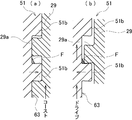
図9、図10は、シフト・フォーク、チェック部、及び噛合いクラッチとの関係を示す概略図、図11は、クラッチ・リングの要部展開図、図12は、噛合いクラッチの噛合いを示し、(a)は、コースト噛合い位置、(b)は、待機噛合い位置を示す要部展開図である。図9〜図12は、第3の噛合いクラッチについて説明する。第1、第2の噛合いクラッチについても同様であり、重複説明は省略する。 9 and 10 are schematic views showing the relationship between the shift fork, the check unit, and the meshing clutch, FIG. 11 is a developed view of the main part of the clutch ring, and FIG. 12 is a diagram showing the meshing of the meshing clutch . (A) is a coast part engagement position, (b) is a principal part expanded view which shows a standby mesh position. 9 to 12 describe the third meshing clutch. The same applies to the first and second meshing clutches, and a duplicate description is omitted.
図1、図9〜図12のように、第3の噛合いクラッチ51は、クラッチ・リング63のクラッチ歯51a、51bと4速ギヤ25、6速ギヤ29のクラッチ歯25a、29aとが、周方向の配置において、歯幅よりも大きな相互間隔を有している。各クラッチ歯51a、51b、25a、29aの周方向噛合い面は、歯の根元が若干細くなるように傾斜形成されている。
As shown in FIGS. 1 and 9 to 12, the third meshing
クラッチ・リング63のクラッチ歯51a、51bの根元には、駆動トルクを受ける噛合い面に前記駆動斜面Fがそれぞれ形成されている。
At the roots of the
したがって、第3の噛合いクラッチ51を、例えば6速ギヤ29に噛合い結合させ、駆動トルクが働くと、図12(b)のように駆動斜面Fによってクラッチ・リング63が移動する。このとき図10に示すシフト・フォーク87の凹部129bがボール133aを押しのけ、スプリング133bは加圧されエネルギーを蓄える。この移動を許すのはシフト・アーム117のガイドに対しシフト溝125に適宜軸方向の遊びを設けているからである。この移動によりクラッチ・リング63は、図9、図12(a)のコースト噛合い位置よりも噛合い離脱側へ移動した図10、図12(b)の離脱待機の位置となる。
次に駆動トルクがコースト方向に変化すると、歯は反対側に押し付けられ、図9、図12に示す駆動斜面Fから離脱する。このため上記スプリング133bの弾性エネルギーにより凹部129b、ボール133aの作用で図9、図12(a)に示す深い噛み合い状態となる。この状態においては、図2に示すカム突部75がカム溝69の軸方向端部側の平坦部69bに位置するため、クラッチ・リング63にスラストは発生しない。
このように、本実施例では、シフト・フォーク87の凹部129b、ボール133a、スプリング133bが、変速下段のクラッチ・リング(59、61、63)のみが噛合いを行った駆動力伝達時に該クラッチ・リング(59、61、63)を第2の噛み合い位置から第1の噛合い位置へ復帰させるための弾性エネルギーを蓄積させる機構を構成し、この機構を変速操作部93側に備えた構成となる。
クラッチ・リング61についてもシフト・フォーク85の凹部127b、ボール131a、スプリング131bが、同様の弾性エネルギーを蓄積させる機構を構成する。
すなわち、変速操作部93側に、変速下段又は変速上段のクラッチ・リング(59、61、63)の一方のみが噛合いを行った駆動力伝達時にクラッチ・リング(59、61、63)に対して弾性エネルギーを蓄積し、コースティング・トルク時にクラッチ・リング(59、61、63)を弾性エネルギーにより第2の噛み合い位置から第1の噛合い位置へ復帰させるための機構を備えた構成となる。
Therefore, when the third meshing
Next, when the driving torque changes in the coast direction, the teeth are pressed to the opposite side and are separated from the driving slope F shown in FIGS. For this reason, the elastic energy of the spring 133b results in the deep meshing state shown in FIGS. 9 and 12 (a) by the action of the recess 129b and the ball 133a. In this state, since the cam projection 75 shown in FIG. 2 is positioned on the flat portion 69 b on the axial end side of the cam groove 69, no thrust is generated in the
As described above, in this embodiment, the recess 129b, the ball 133a, and the spring 133b of the shift fork 87 are engaged with only the clutch ring (59, 61, 63) at the lower gear stage when the driving force is transmitted. A mechanism for accumulating elastic energy for returning the rings (59, 61, 63) from the second meshing position to the first meshing position, and the mechanism provided on the speed change operation unit 93 side; Become.
For the clutch ring 61, the recess 127b of the shift fork 85, the ball 131a, and the spring 131b constitute a mechanism for accumulating similar elastic energy.
That is, when the driving force is transmitted to the shift operation unit 93 side when only one of the clutch ring (59, 61, 63) in the lower shift stage or the upper shift stage is engaged, the clutch ring (59, 61, 63) is transmitted. The structure is equipped with a mechanism for accumulating elastic energy and returning the clutch ring (59, 61, 63) from the second engagement position to the first engagement position by elastic energy during coasting torque. .
一方、変速上段への変速が開始され変速上段及び変速下段が同時噛合いした場合、図1に示すシフト・ドラム119が回転しているので変速下段のシフト溝125の形状によりシフト・アーム117のガイドに対する上記遊びをなくし、コースト・トルクが作用しても第2の噛み合い位置(離脱待機位置)を保持する。
したがって、変速下段と変速上段とのクラッチ・リング(59、61、63)が同時噛合いした時に変速下段又は変速上段のクラッチ・リング(59、61、63)を、第2の噛み合い位置にする機構を備えた構成となる。
このときカム突部75はカム溝69の平坦部69bから斜面部へ移動しているため上段ギヤの噛合いにより、下段ギヤにコースティング・トルクが負荷されると、カム溝69の斜面によりニュートラル方向へ移動するスラスト分力を得ることができる。具体的な変速アクションについては後記する。
[シフト・アップ4速→5速]
図13は、シフト・アップ時トランスミッションの4速ギヤ噛み合いを示す概略図、図14は、シフト・アップ時トランスミッションの4速クラッチ・リングの離脱待機
の位置を示す概略図、図15は、5速に変速終了時の概略図、図16は、シフト・ダウン時、4速5速がニュートラルであることを示す概略図である。
ここでは、説明を簡単にするため、4速(変速下段)から5速(変速上段)へのシフト・アップのみ説明する。他の段のシフト・アップも同様である。
On the other hand, when the shift to the upper shift stage is started and the upper shift stage and the lower shift stage are meshed simultaneously , the shift drum 119 shown in FIG. The play with respect to the guide is eliminated, and the second meshing position (separation standby position) is maintained even when coasting torque is applied.
Therefore, when the clutch ring (59, 61, 63) of the lower shift stage and the upper shift stage is engaged at the same time, the clutch ring (59, 61, 63) of the lower shift stage or the upper shift stage is set to the second engagement position. It becomes the structure provided with the mechanism.
At this time, since the cam protrusion 75 moves from the flat portion 69 b of the cam groove 69 to the slope portion, when a coasting torque is applied to the lower gear due to the meshing of the upper gear, the cam groove 69 is neutralized by the slope of the cam groove 69. A thrust component moving in the direction can be obtained. Specific shift action will be described later.
[Shift up 4th → 5th ]
FIG. 13 is a schematic diagram showing the meshing of the 4-speed gear of the transmission at the time of shift-up, FIG. 14 is a schematic diagram showing the position of waiting for the separation of the 4-speed clutch ring of the transmission at the time of the shift-up, and FIG. FIG. 16 is a schematic diagram showing that the fourth speed and the fifth speed are neutral at the time of shifting down.
Here, for simplification of explanation, only the shift-up from the fourth speed (shift lower stage) to the fifth speed (shift upper stage) will be described. The same applies to the shift-up of other stages.
図13〜図16にシフト・アップ時の動きを示す。図13の4速のクラッチ歯25aにはドライブ・トルクが付加されているため前記したようにクラッチ・リング63は駆動斜面Fの作用により、図14のように離脱待機位置となる。つまり4速位置にあるクラッチ・リング63のカム突部75はカム溝69の斜面に位置することとなる。このときシフト・ドラム119の回転により5速へのシフト・アップ操作が行われると、シフト溝123が働き、シフト・アーム115、シフト・ロッド107、シフト・フォーク85を介してクラッチ・リング61が操作される。この操作によりクラッチ・リング61が5速ギヤ27に噛み合い、4速ギヤ25及び5速ギヤ27が同時噛合いとなる。
FIG. 13 to FIG. 16 show the movement at the time of shifting up. Since drive torque is applied to the fourth-speed clutch teeth 25a in FIG. 13, the
このときエンジン出力トルクの如何に係らず同時噛み合いによる機構的必然による内部循環トルクにより4速側にはコースティング・トルク、5速側にはドライブ・トルクが発生する。このトルクがカム溝69、67の斜面の作用で4速位置にあるクラッチ・リング63には図右側ニュートラル方向、5速位置のクラッチ・リング61には図右側噛み合いを深める方向のスラストが発生し、それぞれのクラッチ・リング63、61を所定の位置に移動し、図15に示すように5速へのシフト・アップを終了させる。
At this time, coasting torque is generated on the 4th speed side and drive torque is generated on the 5th speed side due to the internal circulation torque caused by the mechanical engagement by simultaneous meshing regardless of the engine output torque. This torque is caused by the action of the inclined surfaces of the cam grooves 69 and 67, and the
本発明実施例の特徴は、クラッチ・リング59、61、63が軸方向へ移動するとき、カム溝65、67、69の斜面の作用で、メイン・シャフト3またはカウンター・シャフト5と同回転するカム・リング53、55、57に対して相対的に変速下段側のクラッチ・リング59、61、63は回転が遅れ、変速上段側のクラッチ・リング59、61、63は回転が先行する。このような状況で回転する変速下段と変速上段との歯車のクラッチ歯19a、21a、23a、25a、27a、29aとの相対速度をなくしダブル噛み合いを許容すると共に、シンクロ作用を発生し変速ショックを緩和する。
[エンジンブレーキが働いているときのシフト・アップ]
エンジンブレーキが作用しているときシフト・アップすると、4速位置にあるクラッチ・リング63は待機位置に位置しない状態で変速が行われる。このときシフト・アップ操作によりクラッチ・リング61が5速ギヤ27に噛み合い、4速に更なるコースティング・トルクが働くが、4速位置のクラッチ・リング63は離脱待機位置に無いため、ニュートラル方向へのスラスト分力は発生しない。
A feature of the embodiment of the present invention is that when the clutch rings 59, 61, 63 move in the axial direction, they rotate together with the main shaft 3 or the counter shaft 5 by the action of the inclined surfaces of the cam grooves 65, 67, 69. The rotation of the clutch rings 59, 61, 63 on the lower speed side relative to the cam rings 53, 55, 57 is delayed, and the rotation of the clutch rings 59, 61, 63 on the upper speed side is preceded. In such a situation, the relative speed of the
[Shifting up when the engine brake is working]
When shifting up when the engine brake is applied, the
しかし、(1)エンジンブレーキ時のコースティング・トルクは加速時のトルクに比べ絶対値が小さく、噛み合いクラッチに働く摩擦力は小さい。(2)5速位置のクラッチ・リング61はカム溝67の斜面作用で強力なスラスト分力が発生する。
このスラストが5速位置のシフト・フォーク85、シフト・ロッド107、シフト・ドラム119を経て、4速位置のシフト・ロッド109、シフト・フォーク87へと伝達され、4速位置のクラッチ・リング63を図右側のニュートラル方向へ駆動する。従って、このような場合でもシフト・アップへの支障は生じない。
すなわち、前記変速操作部93を経由し前記変速下段及び変速上段のクラッチ・リング63、61の一方から他方に前記噛合い方向又は噛合い解除方向の必要なスラスト力を伝達する機構を有した構成となる。
However, (1) the coasting torque during engine braking has a smaller absolute value than the torque during acceleration, and the frictional force acting on the meshing clutch is small. (2) The clutch ring 61 at the fifth speed position generates a strong thrust component due to the slope action of the cam groove 67.
This thrust is transmitted to the shift rod 109 and the shift fork 87 at the 4-speed position via the shift fork 85, the shift rod 107, and the shift drum 119 at the 5-speed position, and the
That is, a structure having a mechanism for transmitting a necessary thrust force in the meshing direction or the meshing release direction from one of the lower gear shift stage and the upper gear shift clutch rings 63, 61 to the other via the speed change operation unit 93. It becomes.
またドライブ・トルクが働いている場合であっても、駆動斜面Fがない場合、クラッチ・リング63は離脱待機位置に位置しない。しかし、この場合であっても、上記5速位置のシフト機構からの力の伝達により、強制的にニュートラル方向へクラッチ・リング63を移動できる。
Even when the drive torque is working, if there is no drive slope F, the
このため駆動斜面Fは本発明に必須のものではなく、変速をよりスムースにするためのものである。 For this reason, the driving slope F is not essential for the present invention, and is intended to make shifting more smooth.
また、本実施例はシフト・ドラム119のシフト溝120、121、123、125(円筒カム)によりシフト操作するが、平面カム、または各シフト・ロッドを制御された油圧や電動モーター空気圧等で駆動しても本発明は成立する。
[シフト・ダウン 5速→4速]
減速時は加速時のような、シームレス・シフトの必要性は無い。減速は主にブレーキにより受け持たれ、エンジンからの出力は基本的に関係しないから、エンジンからの駆動トルクやエンジンブレーキトルクが途切れても問題ないためである。このため通常のマニアルトランスミッションと同じように、まず変速上段の5速位置にあるクラッチ・リング61を図16に示すニュートラルに移動させ動力を遮断し、次にクラッチ・リング63を4速ギヤ25に噛み合わせることでシフト・ダウンする。
In this embodiment, the shift groove 120, 121, 123, 125 (cylindrical cam) of the shift drum 119 is used for the shift operation. The flat cam or each shift rod is driven by controlled hydraulic pressure, electric motor air pressure, or the like. Even so, the present invention is established.
[Shift down 5th gear → 4th gear]
When decelerating, there is no need for a seamless shift like during acceleration. This is because the deceleration is mainly handled by the brake, and the output from the engine is basically not related, so there is no problem even if the drive torque or engine brake torque from the engine is interrupted. For this reason, as in a normal manual transmission, first, the clutch ring 61 at the fifth speed position of the upper gear position is moved to the neutral position shown in FIG. 16 to cut off the power, and then the
以上で、図13の噛み合い状態となる。
このように本実施例はシフト・アップとシフト・ダウンで、噛み合い移行の形態が異なることを特徴とする。これは、変速上段と変速下段のシフト・リング61、63が独立しているためと円筒カム119のシフト溝125、123の連携形状による。
Thus, the meshing state of FIG. 13 is obtained.
As described above, the present embodiment is characterized in that the mode of meshing transition is different between shift-up and shift-down. This is due to the fact that the shift rings 61 and 63 of the upper shift stage and the lower shift stage are independent, and due to the cooperative shape of the shift grooves 125 and 123 of the cylindrical cam 119.
以下このようにシフト・アップとシフト・ダウンとで変速 形態を異ならせる機構について図17により説明する。図17は、シフト・アップ、シフト・ダウンのときのドラム溝の作動説明である。
[シフト・アップ 4速→5速]
図13に示す4速時、シフト・アーム117および5速位置のシフト・アーム115は、図17に示す位置115aおよび位置117aにある。シフト・ドラム119がシフト・アップのため図手前側へ回転すると、シフト溝123の斜面123aによりシフト・アーム115が位置115b1から、115b2、115cへと移動する。このときダブル噛み合いが生じシフト・アーム117は、位置117b1位置からカム・リング57のカム溝69の斜面の働きで、位置117b2に自動的に移動しニュートラルとなる。更にシフト・ドラム119の回転で位置117C に移行する。以上で4速から5速へのシフト・アップは終了する。
[シフト・ダウン 5速→4速]
5速でクラッチが噛み合っているとき、シフト・フォーク117はチェック部133により図1に示すようにニュートラル位置に保持されている。シフト・ドラム119が回転し、シフト溝125がシフト・アーム117に対し、図17の位置117b2にあって軸方向の遊びがあっても、上記チェック部133によりシフト・アーム117は位置117b2においてニュートラルに保持される。
Hereinafter, a mechanism for changing the shift mode between the shift-up and the shift-down will be described with reference to FIG. FIG. 17 is a diagram illustrating the operation of the drum groove during shift up and shift down.
[Shift up 4th → 5th]
At the 4th speed shown in FIG. 13, the shift arm 117 and the shift arm 115 at the 5th speed position are at a position 115a and a position 117a shown in FIG. When the shift drum 119 rotates to the front side in order to shift up, the shift arm 115 is moved from the position 115b1 to 115b2 and 115c by the inclined surface 123a of the shift groove 123. At this time, double meshing occurs, and the shift arm 117 automatically moves from the position 117b1 position to the position 117b2 by the action of the inclined surface of the cam groove 69 of the cam ring 57, and becomes neutral. Further, the shift drum 119 rotates to shift to the position 117C. This completes the shift-up from 4th gear to 5th gear.
[Shift down 5th gear → 4th gear]
When the clutch is engaged at the fifth speed, the shift fork 117 is held in the neutral position as shown in FIG. Even if the shift drum 119 rotates and the shift groove 125 is located at the position 117b2 in FIG. 17 with respect to the shift arm 117 and there is play in the axial direction, the check arm 133 causes the shift arm 117 to be neutral at the position 117b2. Retained.
一方、シフト・アーム115は位置115cから、位置115b1に移行し4速、5速とも図16に示すようにニュートラルとなる。 On the other hand, the shift arm 115 shifts from the position 115c to the position 115b1, and becomes neutral as shown in FIG.
更にシフト・ドラム119が回転するとシフト・フォーク117は、位置117b2から位置117aに移行しクラッチ・リング63が4速ギヤ25のクラッチ歯25aと噛み合い、シフト・ダウンにより図13の状態で完了する。
When the shift drum 119 further rotates, the shift fork 117 shifts from the position 117b2 to the position 117a, and the
トランスミッションは上記した変速原理と同一であるが、ガイド部Gのカム溝の斜面の向き及び駆動斜面Fの位置を、クラッチ歯に対し逆位置とし、変速上段と変速下段が同時噛み合いしたとき、ガイド部Gの作用により、変速下段側はクラッチ・リングがより深く噛み合う方向に、変速上段側はニュートラル方向へガイドされるようにすることもできる。 The transmission is the same as the speed change principle described above, but when the cam groove slope direction of the guide portion G and the drive slope face F are in the opposite positions with respect to the clutch teeth, By the action of the portion G, the lower gear side can be guided in the direction in which the clutch ring engages more deeply, and the upper gear side can be guided in the neutral direction.
これは、建機、農機、大型トラック等が低速時の、泥濘地走行または坂道登坂等、速度エネルギーが小さく走行抵抗が大きい場合、より大きな駆動力を得るため、シフト・ダウンが必要となる。このような場面で、通常の噛み合い変速機によりシフト・ダウンする場合、駆動力が短時間であっても途切れると、車両は停止してしまい、登坂が困難となる等の問題が発生する。当発明によれば、駆動力が途切れず変速可能となるため、容易にシフト・ダウンが可能で走行を維持できる。
なお、前記トランスミッション1のガイド部Gによる変速ガイドは、変速操作部93のシフト・アップ動作側のみ、シフト・ダウン動作側のみの何れかに構成することもできる。この場合、他方側のシフト・ダウン動作側又はシフト・アップ動作側は、クラッチのオン、オフ及びシンクロ・メッシュ機構を介した変速構成とすることも可能である。
さらに、エンジンとメイン・シャフト3との間にトルク・コンバータを介設しても良い。この場合、通常の自動変速機では、トルク・コンバータにストール・トルクが存在することからクラッチ歯47a,47b,49a,49b,51a,51b、19a,21a,23a,25a,27a,29aによる断続では切断ができなくなるところ、トルクが存在しても切断ができるガイド部Gを採用したトランスミッション1では、円滑な変速及びエネルギー損失の抑制の双方を確実に達成することができる。
This is because when the construction machinery, agricultural machinery, large trucks, etc. are traveling at a low speed, such as traveling on a muddy ground or climbing a hill, when the speed energy is small and the traveling resistance is large, a greater driving force is required, so a downshift is required. In such a situation, when shifting down with a normal meshing transmission, if the driving force is interrupted even for a short time, the vehicle stops, causing problems such as difficulty in climbing. According to the present invention, since the driving force can be changed without interruption, shifting can be easily performed and traveling can be maintained.
Note that the shift guide by the guide portion G of the transmission 1 may be configured only on the shift / up operation side or only on the shift / down operation side of the shift operation unit 93. In this case, the shift-down operation side or the shift-up operation side on the other side may be configured to change the clutch on / off and through the synchronized mesh mechanism.
Further, a torque converter may be interposed between the engine and the main shaft 3. In this case, in a normal automatic transmission, there is a stall torque in the torque converter. Therefore, the
1 トランスミッション
3 メイン・シャフト(駆動力伝達軸)
5 カウンター・シャフト(駆動力伝達軸)
19 1速ギヤ(変速ギヤ)
21 2速ギヤ(変速ギヤ)
23 3速ギヤ(変速ギヤ)
25 4速ギヤ(変速ギヤ)
27 5速ギヤ(変速ギヤ)
29 6速ギヤ(変速ギヤ)
65,67,69 カム溝
71,73,75 カム突部
77,79,85,87 シフト・フォーク
103,105,107,109 シフト・ロッド
111,113,115,117 シフト・アーム
119 シフト・ドラム
120,121,123,125 シフト溝
131,133 チェック部
47 第1の噛合いクラッチ
49 第2の噛合いクラッチ
51 第3の噛合いクラッチ
59,61,63 クラッチ・リング
93 変速操作部
F 駆動斜面
G ガイド部
M 移動力伝達機構
T 伝達面
1 Transmission 3 Main shaft (drive force transmission shaft)
5 Counter shaft (driving force transmission shaft)
19 1st gear (transmission gear)
21 2nd gear (transmission gear)
23 3rd gear (transmission gear)
25 4-speed gear (transmission gear)
27 5-speed gear (transmission gear)
29 6-speed gear (transmission gear)
65, 67, 69 Cam groove 71, 73, 75 Cam protrusion 77, 79, 85, 87 Shift fork 103, 105, 107, 109 Shift rod 111, 113, 115, 117 Shift arm 119 Shift drum 120 , 121, 123, 125 Shift groove 131, 133 Check portion 47 First mesh clutch 49 Second mesh clutch 51 Third mesh clutch 59, 61, 63 Clutch ring 93 Shift operation portion F Drive slope G Guide part M Movement force transmission mechanism T Transmission surface
Claims (8)
前記クラッチ・リングと前記駆動力伝達軸との間に、前記変速操作部のシフト・アップ動作又はシフト・ダウン動作により変速下段及び変速上段のクラッチ・リングが同時噛合いした時に前記変速下段又は変速上段のクラッチ・リングに噛合い解除方向の軸力を生じさせるガイド部を備えた、
ことを特徴とするトランスミッション。 And gear of a plurality of stages that are rotatably supported in the drive force transmission shaft, a selective said transmission gear into a plurality equipped are the transmission gear in order to shift output selectively coupled to the driving force transmitting shaft A clutch ring capable of meshing , and a speed change operation unit for selectively operating the clutch ring;
Between the driving force transmission shaft and the clutch ring, the transmission lower or shift when the shift lower and shifting the upper clutch ring has had co engaged by the shift-up operation or shift-down operation of the gearshift operating part The upper clutch ring has a guide portion that generates axial force in the meshing release direction.
Transmission characterized by that.
前記クラッチ・リングと前記駆動力伝達軸との間に、前記変速操作部のシフト・アップ動作又はシフト・ダウン動作により変速下段及び変速上段のクラッチ・リングが同時噛合いした時に前記変速下段と変速上段とのクラッチ・リングに噛合い方向と噛合い解除方向との異なる軸力を各別に生じさせるガイド部を備えた、
ことを特徴とするトランスミッション。 And gear of a plurality of stages that are rotatably supported in the drive force transmission shaft, a selective said transmission gear into a plurality equipped are the transmission gear in order to shift output selectively coupled to the driving force transmitting shaft A clutch ring capable of meshing , and a speed change operation unit for selectively operating the clutch ring;
Between the driving force transmission shaft and the clutch ring, the shift lower and shifting when the clutch ring gear lower and shifting the upper by a shift-up operation or shift-down operation of the shift operation unit has had simultaneously meshed The clutch ring with the upper stage is provided with a guide portion that generates different axial forces in the meshing direction and the meshing release direction,
Transmission characterized by that.
前記クラッチ・リングは、前記変速ギヤに対し軸方向の第1の噛合い位置で噛合う状態と前記第1の噛合い位置よりも噛合いを浅くする第2の噛み合い位置で噛合う状態とに移動可能であり、
前記クラッチ・リングが変速下段及び変速上段で同時噛合いした時に前記変速下段又は変速上段のクラッチ・リングを、前記第2の噛み合い位置にする機構を備え、
前記クラッチ・リングと前記駆動力伝達軸との間に、前記変速操作部のシフト・アップ動作又はシフト・ダウン動作により変速下段及び変速上段のクラッチ・リングが同時噛合いした時に前記変速下段又は変速上段のクラッチ・リングに前記第2の噛み合い位置でコースティング・トルクにより噛合い解除方向の軸力を生じさせるガイド部を備えた、
ことを特徴とするトランスミッション。 And gear of a plurality of stages that are rotatably supported in the drive force transmission shaft, a selective said transmission gear into a plurality equipped are the transmission gear in order to shift output selectively coupled to the driving force transmitting shaft A clutch ring capable of meshing , and a speed change operation unit for selectively operating the clutch ring;
The clutch ring engages with the transmission gear at a first meshing position in the axial direction and at a second meshing position where the meshing is shallower than the first meshing position. Is movable,
A mechanism for bringing the clutch ring of the lower shift stage or the upper shift stage into the second engagement position when the clutch ring is engaged at the lower stage and the upper stage at the same time;
Between the driving force transmission shaft and the clutch ring, the transmission lower or shift when the shift lower and shifting the upper clutch ring has had co engaged by the shift-up operation or shift-down operation of the gearshift operating part The upper clutch ring includes a guide portion that generates an axial force in a meshing release direction by a coasting torque at the second meshing position .
Transmission characterized by that.
前記クラッチ・リングは、前記変速ギヤに対し軸方向の第1の噛合い位置で噛合う状態と前記第1の噛合い位置よりも噛合いを浅くする第2の噛み合い位置で噛合う状態とに移動可能であり、
前記クラッチ・リングが同時噛合いした時に前記変速下段又は変速上段のクラッチ・リングを、前記第2の噛み合い位置にする機構を備え、
前記クラッチ・リングと前記駆動力伝達軸との間に、前記変速操作部のシフト・アップ動作又はシフト・ダウン動作により変速下段及び変速上段のクラッチ・リングが同時噛合いした時に前記変速下段と変速上段とのクラッチ・リングに前記第2の噛み合い位置でコースティング・トルクにより噛合い方向と噛合い解除方向との異なる軸力を各別に生じさせるガイド部を備えた、
ことを特徴とするトランスミッション。 A plurality of speed change gears supported rotatably on the driving force transmission shaft, and a plurality of speed change gears are selectively connected to the driving force transmission shaft and selectively output to the speed change gear. A clutch ring capable of meshing, and a speed change operation unit for selectively operating the clutch ring;
The clutch ring engages with the transmission gear at a first meshing position in the axial direction and at a second meshing position where the meshing is shallower than the first meshing position. Is movable,
A mechanism for setting the clutch ring of the lower gear stage or the upper gear stage to the second meshing position when the clutch rings are engaged at the same time;
When the lower and upper clutch rings are simultaneously meshed between the clutch ring and the driving force transmission shaft by the shift-up operation or the shift-down operation of the shift operation unit, The clutch ring with the upper stage includes a guide portion that generates different axial forces in the meshing direction and the meshing release direction by the coasting torque at the second meshing position.
Transmission characterized by that.
前記ガイド部は、前記クラッチ・リング側と前記駆動力伝達軸側とに各別に設けたカム溝とこのカム溝にガイドされるカム突部とを備えた、
ことを特徴とするトランスミッション。 The transmission according to any one of claims 1 to 4,
The guide portion includes cam grooves provided separately on the clutch ring side and the driving force transmission shaft side, and cam protrusions guided by the cam grooves,
Transmission characterized by that.
前記クラッチ・リングと前記変速ギヤとの選択的な噛合いはクラッチ歯で行われ、
前記クラッチ・リングを前記第2の噛み合い位置にする機構は、前記クラッチ歯の何れか一方の回転方向一側の歯元に形成され駆動力伝達時に前記クラッチ歯の他方の先端部との間の相対的なガイドにより前記クラッチ・リングを前記第1の噛合い位置から前記第2の噛み合い位置へ移動させる駆動斜面を備えた、
ことを特徴とするトランスミッション。 The transmission according to any one of claims 1 to 5,
The selective engagement between the clutch ring and the transmission gear is performed by clutch teeth,
The mechanism for setting the clutch ring to the second meshing position is formed at the tooth base on one side in the rotational direction of any one of the clutch teeth, and between the other tip of the clutch teeth when driving force is transmitted. A drive ramp that moves the clutch ring from the first engagement position to the second engagement position by a relative guide;
Transmission characterized by that.
前記変速操作部を経由し前記変速下段及び変速上段のクラッチ・リングの一方から他方に前記噛合い方向又は噛合い解除方向の必要なスラスト力を前記クラッチ・リングに伝達する機構を有する、
ことを特徴とするトランスミッション。 The transmission according to any one of claims 1 to 5,
A mechanism for transmitting a required thrust force in the meshing direction or the meshing release direction to the clutch ring from one of the lower gear and the upper gear clutch ring to the other via the speed change operation unit;
Transmission characterized by that.
前記変速操作部側に、前記変速下段又は変速上段のクラッチ・リングの一方のみが前記噛合いを行った駆動力伝達時に前記噛合い歯又は被噛合い歯の他方を第2の噛み合い位置から前記第1の噛合い位置へ復帰させるためのエネルギーを蓄積し、コースティング・トルク時に前記クラッチ・リングを前記弾性エネルギーにより前記第2の噛み合い位置から前記第1の噛合い位置へ復帰させるための機構を備えた、
ことを特徴とするトランスミッション。 A transmission according to any one of claims 1-7,
When the driving force is transmitted when only one of the clutch ring at the lower gear stage or the upper gear stage is engaged with the shift operation unit side, the other of the meshing teeth or the meshed teeth is moved from the second meshing position to the gearing operation unit side. A mechanism for accumulating energy for returning to the first meshing position and for restoring the clutch ring from the second meshing position to the first meshing position by the elastic energy during coasting torque With
Transmission characterized by that.
Priority Applications (6)
| Application Number | Priority Date | Filing Date | Title |
|---|---|---|---|
| JP2010281737A JP5707119B2 (en) | 2010-12-17 | 2010-12-17 | transmission |
| US13/988,447 US9175765B2 (en) | 2010-11-19 | 2011-11-04 | Transmission and shift control system |
| EP11841516.5A EP2650560B1 (en) | 2010-11-19 | 2011-11-04 | Transmission and shift control system |
| PCT/JP2011/006172 WO2012066740A1 (en) | 2010-11-19 | 2011-11-04 | Transmission and shift control system |
| CN201180055617.8A CN103299104B (en) | 2010-11-19 | 2011-11-04 | Speed changer and change control system |
| US14/859,613 US10035512B2 (en) | 2010-11-19 | 2015-09-21 | Transmission and shift control system |
Applications Claiming Priority (1)
| Application Number | Priority Date | Filing Date | Title |
|---|---|---|---|
| JP2010281737A JP5707119B2 (en) | 2010-12-17 | 2010-12-17 | transmission |
Publications (3)
| Publication Number | Publication Date |
|---|---|
| JP2012127471A JP2012127471A (en) | 2012-07-05 |
| JP2012127471A5 true JP2012127471A5 (en) | 2014-08-14 |
| JP5707119B2 JP5707119B2 (en) | 2015-04-22 |
Family
ID=46644732
Family Applications (1)
| Application Number | Title | Priority Date | Filing Date |
|---|---|---|---|
| JP2010281737A Active JP5707119B2 (en) | 2010-11-19 | 2010-12-17 | transmission |
Country Status (1)
| Country | Link |
|---|---|
| JP (1) | JP5707119B2 (en) |
Families Citing this family (35)
| Publication number | Priority date | Publication date | Assignee | Title |
|---|---|---|---|---|
| JP5452681B1 (en) * | 2012-09-14 | 2014-03-26 | 富士重工業株式会社 | transmission |
| JP5945484B2 (en) * | 2012-09-20 | 2016-07-05 | アイシン・エーアイ株式会社 | Vehicle transmission |
| JP6002009B2 (en) * | 2012-11-20 | 2016-10-05 | 富士重工業株式会社 | Power transmission mechanism and transmission |
| JP2014122676A (en) * | 2012-12-21 | 2014-07-03 | Ikeya Formula Kk | Slope start assisting system |
| JP6180438B2 (en) * | 2012-12-25 | 2017-08-16 | 株式会社イケヤフォ−ミュラ | Shift control system |
| JP5790701B2 (en) | 2013-04-15 | 2015-10-07 | 株式会社豊田中央研究所 | Clutch mechanism and transmission |
| JP6251585B2 (en) * | 2014-01-30 | 2017-12-20 | 株式会社イケヤフォ−ミュラ | transmission |
| JP6416568B2 (en) * | 2014-09-19 | 2018-10-31 | 株式会社イケヤフォ−ミュラ | transmission |
| JP6330194B2 (en) * | 2015-03-20 | 2018-05-30 | ジヤトコ株式会社 | Control device for automatic transmission |
| JP6262400B2 (en) * | 2015-03-20 | 2018-01-17 | ジヤトコ株式会社 | Automatic transmission |
| JP6298997B2 (en) * | 2015-05-08 | 2018-03-28 | ジヤトコ株式会社 | Automatic transmission |
| JP6561335B2 (en) * | 2015-05-18 | 2019-08-21 | ジヤトコ株式会社 | Automatic transmission |
| WO2017017723A1 (en) * | 2015-07-24 | 2017-02-02 | 株式会社ユニバンス | Transmission |
| US10968960B2 (en) | 2015-07-24 | 2021-04-06 | Univance Corporation | Transmission |
| JP6590569B2 (en) * | 2015-07-27 | 2019-10-16 | 株式会社ユニバンス | transmission |
| JP2017207181A (en) * | 2016-05-20 | 2017-11-24 | 本田技研工業株式会社 | Speed change gear |
| CN109642667B (en) * | 2016-09-05 | 2021-02-02 | 秦内蒂克有限公司 | Speed variator |
| JP6654751B2 (en) | 2016-09-14 | 2020-02-26 | トヨタ自動車株式会社 | Transmission for vehicles |
| JP6577441B2 (en) | 2016-10-27 | 2019-09-18 | トヨタ自動車株式会社 | Dog clutch |
| JP2018071627A (en) * | 2016-10-27 | 2018-05-10 | ジヤトコ株式会社 | Automatic transmission |
| JP6750166B2 (en) * | 2016-11-08 | 2020-09-02 | ジヤトコ株式会社 | Automatic transmission |
| JP2018115733A (en) * | 2017-01-20 | 2018-07-26 | ジヤトコ株式会社 | Rotation transmission mechanism |
| JP2018115734A (en) * | 2017-01-20 | 2018-07-26 | ジヤトコ株式会社 | Rotation transmission mechanism |
| JP6762670B2 (en) * | 2017-01-20 | 2020-09-30 | ジヤトコ株式会社 | Rotation transmission mechanism |
| JP6794052B2 (en) * | 2017-03-01 | 2020-12-02 | ジヤトコ株式会社 | Drive device and transmission for seamless mechanism |
| JP2018145974A (en) * | 2017-03-01 | 2018-09-20 | ジヤトコ株式会社 | Drive device for seamless mechanism, and transmission |
| JP6553666B2 (en) | 2017-03-22 | 2019-07-31 | 株式会社豊田中央研究所 | Dog clutch and transmission |
| JP6385522B2 (en) * | 2017-05-19 | 2018-09-05 | 株式会社イケヤフォ−ミュラ | Slope start assist device |
| JP7170966B2 (en) | 2018-10-10 | 2022-11-15 | マツダ株式会社 | vehicle drive |
| JP6669835B2 (en) * | 2018-10-19 | 2020-03-18 | 株式会社イケヤフォ−ミュラ | transmission |
| JP7191465B2 (en) * | 2018-11-20 | 2022-12-19 | ジヤトコ株式会社 | Seamless shift mechanism and transmission |
| JP7385676B2 (en) | 2019-12-13 | 2023-11-22 | 株式会社ユニバンス | transmission |
| JP7391106B2 (en) | 2019-12-13 | 2023-12-04 | 株式会社ユニバンス | transmission |
| WO2021117218A1 (en) * | 2019-12-13 | 2021-06-17 | 株式会社ユニバンス | Transmission |
| JP7061660B1 (en) | 2020-12-23 | 2022-04-28 | 株式会社ユニバンス | Power transmission device |
Family Cites Families (3)
| Publication number | Priority date | Publication date | Assignee | Title |
|---|---|---|---|---|
| US4964313A (en) * | 1988-10-24 | 1990-10-23 | Eaton Corporation | Two-speed gear train assembly |
| JPH0799193B2 (en) * | 1990-10-04 | 1995-10-25 | 石川島芝浦機械株式会社 | Gear change device |
| JP4542809B2 (en) * | 2004-04-23 | 2010-09-15 | 株式会社イケヤフォ−ミュラ | Torque interrupting device |
-
2010
- 2010-12-17 JP JP2010281737A patent/JP5707119B2/en active Active
Similar Documents
| Publication | Publication Date | Title |
|---|---|---|
| JP5707119B2 (en) | transmission | |
| JP2012127471A5 (en) | ||
| WO2012066740A1 (en) | Transmission and shift control system | |
| WO2017026535A1 (en) | Transmission | |
| JP2003314635A (en) | Automatic transmission | |
| JP6416568B2 (en) | transmission | |
| JP5545778B2 (en) | transmission | |
| JP6180438B2 (en) | Shift control system | |
| JP2016114227A (en) | Vehicular transmission | |
| JP6251585B2 (en) | transmission | |
| JP2015140892A (en) | transmission | |
| JP5658068B2 (en) | Transmission | |
| JP7197906B2 (en) | Transmission and dog clutch | |
| JP2007120549A (en) | Automatic transmission | |
| JP4372185B2 (en) | transmission | |
| JP6669835B2 (en) | transmission | |
| JP2014122676A (en) | Slope start assisting system | |
| JP6775821B2 (en) | Shift control system | |
| JP5439555B2 (en) | transmission | |
| JP5169878B2 (en) | Dual clutch transmission | |
| JP2009074637A (en) | Shift-up method in transmission | |
| JP2020008071A (en) | Transmission for vehicle | |
| JP5658069B2 (en) | Transmission | |
| JP6068866B2 (en) | transmission | |
| JP2017166700A (en) | Slope start auxiliary device |