JP2012106914A - Polycrystalline silicon cleaning apparatus - Google Patents
Polycrystalline silicon cleaning apparatus Download PDFInfo
- Publication number
- JP2012106914A JP2012106914A JP2011229023A JP2011229023A JP2012106914A JP 2012106914 A JP2012106914 A JP 2012106914A JP 2011229023 A JP2011229023 A JP 2011229023A JP 2011229023 A JP2011229023 A JP 2011229023A JP 2012106914 A JP2012106914 A JP 2012106914A
- Authority
- JP
- Japan
- Prior art keywords
- basket
- polycrystalline silicon
- cleaning
- rod
- cleaning apparatus
- Prior art date
- Legal status (The legal status is an assumption and is not a legal conclusion. Google has not performed a legal analysis and makes no representation as to the accuracy of the status listed.)
- Granted
Links
Images


Landscapes
- Cleaning By Liquid Or Steam (AREA)
- Silicon Compounds (AREA)
Abstract
【課題】不純物を確実に除去して優れた洗浄効果を得るとともに、作業性を向上させることのできる多結晶シリコンの洗浄装置を提供する。
【解決手段】洗浄槽2の洗浄室21〜25内に、異なる勾配の載置面61を有する支持台6が複数配設され、バスケット3は、その両側部に、吊り上げ機42により係止される突出部35がバスケット3の幅方向外方に突出し、かつ、長さ方向に間隔をあけて相互に平行に一対ずつ設けられてなり、支持台6は、その両側部に、載置面61にバスケット3を載置する際に、一対の突出部35の間に配置され、支持台6の載置面61よりも上方に突出する一対のガイドフレーム7が上下方向に沿って立設されている。
【選択図】 図1Provided is a polycrystalline silicon cleaning apparatus capable of reliably removing impurities to obtain an excellent cleaning effect and improving workability.
A plurality of support bases 6 having mounting surfaces 61 with different slopes are disposed in cleaning chambers 21 to 25 of a cleaning tank 2, and a basket 3 is locked on both sides thereof by a lifting machine 42. The protruding portions 35 protrude outward in the width direction of the basket 3 and are provided in pairs in parallel with each other at intervals in the length direction. When the basket 3 is placed on the pair, a pair of guide frames 7 disposed between the pair of projecting portions 35 and projecting upward from the placement surface 61 of the support base 6 are erected along the vertical direction. Yes.
[Selection] Figure 1
Description
本発明は、半導体用単結晶シリコン及び太陽電池用シリコンの原料となる多結晶シリコンの洗浄装置に関する。 The present invention relates to a cleaning apparatus for polycrystalline silicon used as a raw material for single crystal silicon for semiconductors and silicon for solar cells.
半導体用単結晶シリコン及び太陽電池用シリコンの原料となる多結晶シリコンは、シーメンス法等によりロッド状に製作した後、薬液で洗浄して、表面に付着した不純物を除去することが行われている。 Polycrystalline silicon, which is a raw material for single crystal silicon for semiconductors and silicon for solar cells, is manufactured in a rod shape by the Siemens method or the like, and then washed with a chemical solution to remove impurities adhering to the surface. .
多結晶シリコンの洗浄装置として、例えば、特許文献1には、多結晶シリコンの切断ロッドを収納したバスケットをフッ酸と硝酸との混合液を入れた洗浄槽に浸漬して、多結晶シリコン表面を溶解(エッチング)することによって不純物を除去する装置が提案されている。この装置においては、洗浄槽の内底部にバスケットを載置する支持台が、その上面を洗浄槽ごとに交互に逆向きに傾斜した状態に設けられている。これにより、多結晶シリコンのロッドを収納したバスケットが各洗浄槽に移し換えられる際に、洗浄槽内で交互に傾斜させられることによってロッドが揺動し、洗浄効果を高めることができる。 As a polycrystalline silicon cleaning apparatus, for example, in Patent Document 1, a basket containing a polycrystalline silicon cutting rod is immersed in a cleaning tank containing a mixed solution of hydrofluoric acid and nitric acid, and the surface of the polycrystalline silicon is coated. An apparatus for removing impurities by dissolving (etching) has been proposed. In this apparatus, the support base for placing the basket on the inner bottom of the cleaning tank is provided in a state where the upper surface thereof is alternately inclined in the opposite direction for each cleaning tank. Thereby, when the basket containing the rods of polycrystalline silicon is transferred to each cleaning tank, the rods are swung by being alternately inclined in the cleaning tank, and the cleaning effect can be enhanced.
また、この装置は、バスケットの吊り上げ機に回転自在なフックを軸支しており、このフックとバスケットの係合部とを係合させて、バスケットを上下動させる構成としている。そのため、洗浄槽内にバスケットを浸漬して支持台に載置する際、バスケット内のシリコンロッドが、支持台の傾斜によりバスケット内で転がることによりバスケットの揺動が生じ、載置位置がずれると、バスケットを再度引き上げる際にバスケットとフックとの係合部がずれる等して、作業性が悪かった。 Further, this device is configured such that a rotatable hook is pivotally supported on a basket lifting machine, and the basket is moved up and down by engaging the hook with an engaging portion of the basket. For this reason, when the basket is immersed in the washing tank and placed on the support table, if the silicon rod in the basket rolls in the basket due to the inclination of the support table, the basket swings and the placement position shifts. When the basket was pulled up again, the workability was poor because the engagement portion between the basket and the hook was displaced.
本発明は、このような事情に鑑みてなされたもので、多結晶シリコンロッドの表面の不純物を確実に除去して優れた洗浄効果を得るとともに、作業性を向上させることのできる多結晶シリコンの洗浄装置を提供する。 The present invention has been made in view of such circumstances, and it is possible to reliably remove impurities on the surface of the polycrystalline silicon rod to obtain an excellent cleaning effect and improve the workability of the polycrystalline silicon. A cleaning device is provided.
本発明の多結晶シリコン洗浄装置は、バスケットに複数の多結晶シリコンのロッドを収納し、前記バスケットを吊り上げ機により洗浄槽に浸漬して洗浄する多結晶シリコンの洗浄装置であって、前記洗浄槽の内底部に前記バスケットを支持する載置面を有する支持台が複数設けられ、前記載置面は水平方向と平行な水平面、水平方向に対して左勾配とされた左勾配面又は水平方向に対して右勾配とされた右勾配面のいずれかに形成されるとともに、前記複数の支持台のうち、少なくとも一つは他の支持台とは異なる勾配の前記載置面を有しており、前記バスケットは、その両側部に、前記吊り上げ機により下方から支持される突出部が前記バスケットの幅方向外方に突出し、かつ、長さ方向に間隔をあけて相互に平行に一対ずつ設けられてなり、前記支持台は、その両側部に、前記載置面に前記バスケットを載置する際に、一対の前記突出部の間に配置され、前記支持台の載置面よりも上方に突出する一対のガイドフレームが上下方向に沿って立設されていることを特徴とする。 The polycrystalline silicon cleaning apparatus of the present invention is a polycrystalline silicon cleaning apparatus in which a plurality of polycrystalline silicon rods are accommodated in a basket, and the basket is immersed in a cleaning tank by a lifting machine and cleaned. A plurality of support bases having a mounting surface for supporting the basket are provided on the inner bottom of the base plate, and the mounting surface is a horizontal plane parallel to the horizontal direction, a left inclined plane that is inclined to the left with respect to the horizontal direction, or a horizontal direction. It is formed on one of the right slope surfaces that are right slopes, and at least one of the plurality of support bases has the mounting surface described above with a slope different from that of the other support bases, The basket is provided with a pair of projecting portions supported from below by the lifting machine projecting outward in the width direction of the basket and a pair parallel to each other at intervals in the length direction. Na The support table is disposed between the pair of protrusions when the basket is mounted on the mounting surface on both sides of the support table, and protrudes above the mounting surface of the support table. The guide frame is erected along the vertical direction.
従来のバスケットでは、バスケットを傾斜面に載置する際、あるいは載置面から引き上げる際に、バスケット内の多結晶シリコンのロッドが転がることにより、ロッド同士が接触もしくは衝突してロッドに欠けや割れが生じており、形状不良が多かった。
この多結晶シリコン洗浄装置においては、多結晶シリコンのロッドを収納したバスケットを吊り上げ機により複数の支持台に載置する際に、バスケットの両側面及び突出部がガイドフレームに沿って上下方向に案内されるので、傾斜した載置面であっても、その上にバスケットを案内して確実に載置させることができる。
また、吊り上げ機によりバスケットを吊り下げた状態として、傾斜した載置面の上下寸法よりも大きくバスケットを上下動させることにより、洗浄槽内において自動的にバスケットを傾けて揺動させ、バスケット内のロッドを転動させながらロッド表面を均一に洗浄することができ、ロッド表面の不純物を確実に除去して優れた洗浄効果を得ることができる。この場合、バスケットはガイドフレームによって側方への移動が所定範囲内で規制された状態であるので、常に所定位置に配置される。
さらに、ガイドフレームによってバスケットが常に所定位置に配置されることから、バスケットを再度引き上げる際にも、確実にバスケットの突出部を支持して搬出することができる。このように、バスケットの搬入、上下動、搬出の三段階の作業をガイドフレームに沿って確実に行えるようにしたので、作業性を向上させることができる。
In conventional baskets, when the basket is placed on an inclined surface or pulled up from the placement surface, the polycrystalline silicon rods in the basket roll, causing the rods to contact or collide with each other, causing the rods to chip or crack. There were many shape defects.
In this polycrystalline silicon cleaning apparatus, when a basket containing polycrystalline silicon rods is placed on a plurality of support bases by a lifting machine, both side surfaces and protrusions of the basket are guided vertically along the guide frame. Therefore, even if the mounting surface is inclined, the basket can be guided and reliably mounted on the inclined mounting surface.
In addition, when the basket is suspended by a lifting machine, the basket is automatically tilted and swung in the washing tank by moving the basket up and down larger than the vertical dimension of the inclined mounting surface. The rod surface can be cleaned uniformly while rolling the rod, and impurities on the rod surface can be reliably removed to obtain an excellent cleaning effect. In this case, the basket is always arranged at a predetermined position because the lateral movement of the basket is restricted within a predetermined range by the guide frame.
Further, since the basket is always arranged at a predetermined position by the guide frame, the protruding portion of the basket can be reliably supported and carried out even when the basket is pulled up again. As described above, since the three steps of loading, lifting, and unloading of the basket can be reliably performed along the guide frame, workability can be improved.
また、本発明の多結晶シリコン洗浄装置において、前記バスケット内に、前記ロッドの間に配置されて前記ロッド相互の衝突を防止する樹脂製の緩衝棒が設けられており、前記緩衝棒に、大径部が長さ方向に間隔をおいて複数設けられているとよい。
複数の大径部を有する緩衝棒が、バスケットの揺動に伴ってロッドと共にバスケット内を回転して移動し、ロッド相互の接触や衝突を防止してロッドの割れや欠け等を防止することができる。
緩衝棒の大径部を設けることで、大径部を設けない場合と比べて、緩衝棒とロッドとの接触が少なくなり、大径部のみとの接触となることより、全体としてロッドと接触する部分の面積が小さくなる。また、大径部を設けることにより、緩衝棒がバスケット底面より浮いた形となるので、バスケット内の洗浄液の流れが緩衝棒によって遮られることが防止され、バスケット内での洗浄液の濃度差が生じ難くなる。これにより、均一な濃度の洗浄液がロッド表面に一様に行き渡るようになり、洗浄液との接触が妨げられにくくなるため、ロッド表面のエッチングのばらつきが抑制され、均一な洗浄を行うことができる。
In the polycrystalline silicon cleaning apparatus of the present invention, a resin buffer rod disposed between the rods to prevent the rods from colliding with each other is provided in the basket. A plurality of diameter portions may be provided at intervals in the length direction.
A buffer rod having a plurality of large-diameter portions rotates and moves in the basket together with the rod as the basket swings, preventing mutual contact and collision of the rods and preventing cracks and chipping of the rods. it can.
By providing the large-diameter portion of the buffer rod, the contact between the buffer rod and the rod is reduced compared to the case where the large-diameter portion is not provided, and only the large-diameter portion is contacted. The area of the portion to be reduced is reduced. In addition, since the buffer rod is lifted from the bottom of the basket by providing the large diameter portion, the flow of the cleaning liquid in the basket is prevented from being blocked by the buffer rod, resulting in a difference in concentration of the cleaning liquid in the basket. It becomes difficult. As a result, the cleaning liquid having a uniform concentration can be uniformly distributed on the rod surface, and the contact with the cleaning liquid is hardly hindered. Therefore, variation in etching of the rod surface can be suppressed and uniform cleaning can be performed.
また、本発明の多結晶シリコン洗浄装置において、前記バスケットの幅方向中央部に、その内部空間を長さ方向に沿って拡げた延長部が設けられ、前記延長部の底部を貫通する開口部が設けられているとよい。
棒状のロッドをバスケットの中に入れる場合、長さの長いロッドでは、長さの短いロッドに比べて、バスケット内の洗浄液の液循環が悪かった。
本発明の多結晶シリコン洗浄装置においては、バスケットの幅方向中央部を長さ方向に拡げて延長部および開口部が形成されているので、バスケットの上下動時に開口部から内部空間に洗浄液を流通させることができ、バスケット内の液循環を促進させることができる。
Further, in the polycrystalline silicon cleaning apparatus of the present invention, an extension that extends the inner space along the length direction is provided in the central portion in the width direction of the basket, and an opening that penetrates the bottom of the extension is provided. It should be provided.
When a rod-shaped rod was placed in the basket, the long-length rod was poor in circulation of the cleaning liquid in the basket as compared to the short-length rod.
In the polycrystalline silicon cleaning apparatus of the present invention, the central part in the width direction of the basket is expanded in the length direction to form the extension part and the opening part, so that the cleaning liquid is circulated from the opening part to the internal space when the basket moves up and down. And the circulation of the liquid in the basket can be promoted.
さらに、本発明の多結晶シリコン洗浄装置において、前記バスケットの内面には、凸条が前記バスケットの長さ方向に間隔をおいて複数設けられているとよい。
バスケットの内面とロッドとが接触していると、その接触部分が洗浄(エッチング)不足となり、ロッド表面に付着している不純物が十分に除去できないために、エッチング斑が生じて、エッチングのばらつきが生じ易かった。また、ロッドがバスケット内で転がることにより、バスケットの内面に衝突し、ロッドの割れや欠けが生じ易かった。さらに、ロッドの切断面のエッジ部によってバスケットの内面が削られるために、バスケットの交換頻度が多くなるだけでなく、その削られた破片がロッドに付着して品質に悪影響を及ぼしていた。
本発明の多結晶シリコン洗浄装置においては、バスケットの内面に複数の凸条が設けられているので、バスケットの内面とロッドとの接触面積を小さくすることができ、ロッド表面のエッチングのばらつきを低減することができる。
また、凸条により搬送時の揺れ等による衝撃を吸収して、ロッドの割れや欠けを防止することができるとともに、バスケット内でロッドが転がった際に、ロッドの切断面のエッジ部でバスケット内面が削られるのを低減することができる。
Furthermore, in the polycrystalline silicon cleaning apparatus of the present invention, a plurality of protrusions may be provided on the inner surface of the basket at intervals in the length direction of the basket.
When the inner surface of the basket and the rod are in contact, the contact portion becomes insufficiently cleaned (etched), and impurities adhering to the rod surface cannot be sufficiently removed, resulting in etching spots and uneven etching. It was easy to occur. Further, when the rod rolls in the basket, it collides with the inner surface of the basket, and the rod is easily cracked or chipped. Further, since the inner surface of the basket is scraped by the edge portion of the cut surface of the rod, not only the basket is frequently replaced, but also the scraped pieces adhere to the rod and adversely affect the quality.
In the polycrystalline silicon cleaning apparatus of the present invention, a plurality of protrusions are provided on the inner surface of the basket, so that the contact area between the inner surface of the basket and the rod can be reduced, and variation in etching of the rod surface is reduced. can do.
In addition, it can absorb the impact caused by shaking during transportation by the ridges and prevent cracking and chipping of the rod, and when the rod rolls in the basket, the inner surface of the basket at the edge of the cutting surface of the rod Can be reduced.
本発明によれば、多結晶シリコンのロッドを収納したバスケットを、載置面の勾配を異ならせた複数の支持台に順次載置することにより、自動的にバスケットを傾けて揺動させることができるので、バスケットに収納したロッドを転動させながらロッド表面を均一に洗浄することができ、ロッド表面の不純物を確実に除去して優れた洗浄効果を得ることができる。この場合、ガイドフレームによって洗浄槽内におけるバスケットの側方への移動を所定範囲内に規制しているので、バスケットの搬入、上下動、搬出の三段階の作業をガイドフレームに沿って確実に行え、作業性を向上させることができる。 According to the present invention, the basket containing the polycrystalline silicon rods can be automatically tilted and swung by sequentially placing the basket on a plurality of support bases with different slopes of the placement surface. Therefore, the rod surface can be washed uniformly while rolling the rod stored in the basket, and impurities on the rod surface can be surely removed to obtain an excellent washing effect. In this case, since the lateral movement of the basket in the cleaning tank is regulated within a predetermined range by the guide frame, the three stages of basket loading, vertical movement, and unloading can be reliably performed along the guide frame. Workability can be improved.
以下、本発明の多結晶シリコン洗浄装置の一実施形態を、図面を参照しながら説明する。
この実施形態の多結晶シリコン洗浄装置100は、適当な長さに切断して得られる多結晶シリコンのロッドRをバスケット3に収納した状態で洗浄する装置である。
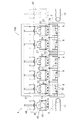
多結晶シリコン洗浄装置は複数の洗浄室からなる洗浄槽により構成されるが、本実施形態の多結晶シリコン洗浄装置100においては、図1に示すように、洗浄液である酸液を満たした三つの洗浄室21〜23と、純水を満たした二つの洗浄室24,25とが一直線上に並べられて洗浄槽2が構成される。各洗浄室21〜25は、その配列方向に沿う寸法より、これと直交する方向の寸法が、長く形成されている。酸液には、例えば、フッ酸と硝酸との混合液が用いられ、各洗浄室21〜23ごとにフッ酸と硝酸との混合比率が異なる混合液が用いられる。
Hereinafter, an embodiment of a polycrystalline silicon cleaning apparatus of the present invention will be described with reference to the drawings.
The polycrystalline
The polycrystalline silicon cleaning apparatus is constituted by a cleaning tank composed of a plurality of cleaning chambers. In the polycrystalline
多結晶シリコン洗浄装置100の上方には、ロッドRを収納したバスケット3を各洗浄室21〜25に順次搬送するための搬送手段4が設けられている。
搬送手段4には、例えば、各洗浄室21〜25の上方に設けられたレール41に沿って移送可能に支持される吊り上げ機42が備えられる。この吊り上げ機42によって、ロッドRを収納したバスケット3が上下動可能に吊り下げられる構成とされており、バスケット3を支持して、各洗浄室21〜25の上方から昇降移動し、また洗浄室21〜25の間を移動して各洗浄室21〜25にバスケット3を出し入れすることにより、所定時間、洗浄室21〜25内の洗浄液に浸漬させるようになっている。
Above the polycrystalline
The transport means 4 includes, for example, a lifting
バスケット3の上下動時には、洗浄室内の酸液または純水に波が発生し、これらの液が隣接する洗浄室に入ることがある。その場合、各洗浄室内の液組成に変動が生じて、エッチングのバラツキを引き起こすことがあるため、各洗浄室21〜25の間に配置される各仕切板26の上方には、隣接する洗浄室に酸液または純水が混入するのを防止するために波返し板27が設けられている。波返し板27は、図1に示すように、その下端部が各仕切板26の上方に取り付けられ、上端部が洗浄室内方に突出して設けられている。
When the
酸液の洗浄室21,22には、洗浄液中の微粒子や不純物を除去した後に、再び洗浄室21,22に戻す循環路(不図示)が設けられている。また、純水の洗浄室24,25は、洗浄室内下部に純水を供給して上部からオーバーフローさせることにより、液中に浮遊するシリコンの微粉末や不純物等を純水とともに排出させている。
The
洗浄室21〜25の列の一端の搬入側には、バスケット3の搬入装置11が設置される。また、他端の搬出側には、搬出装置12が設置される。これら搬入装置11および搬出装置12は、例えばベルトコンベアを用いることができる。
A carry-in
各洗浄室21〜25の内底部には、バスケット3を載せる載置面61が形成された支持台6が備えられている。
支持台6は、4枚の垂直な平板を井桁状に組み合わせてなるフレーム62の中央部を、その4つの交差部を結ぶ角筒より大きく所定深さまで切欠することにより、バスケット3を載置可能に、上方を開放した形状に載置面61が形成される。
バスケット3を載置する載置面61は、図1に示すように、水平方向と平行な水平面、水平方向に対して左勾配とされた左勾配面又は水平方向に対して右勾配とされた右勾配面のいずれかに形成されている。また、各洗浄室21〜25内の支持台6は、異なる勾配の載置面61を有する支持台6が隣接するように配設されており、図1に示す例では、搬入側から、左勾配面、右勾配面、水平面、右勾配面、左勾配面の載置面61を有する支持台6が順に並べられている。
At the inner bottom of each of the
The
As shown in FIG. 1, the
各支持台6の両側部には、バスケット3の側方への移動を所定の範囲内で規制する一対のガイドフレーム7が上下方向に沿って支持台6の載置面61よりも上方に突出して立設されている。このガイドフレーム7は、洗浄室21〜25の列と直交する方向に沿う平板状に形成され、支持台6を介して対向するように配設されており、互いの対向面71でバスケット3のレール41に沿う方向(バスケット3の幅方向)の移動を規制するとともに、後述するバスケット3の突出部35の間に配置されることで、レール41に直交する方向(バスケット3の長さ方向)の移動を規制する。
A pair of guide frames 7 for restricting lateral movement of the
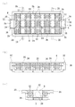
バスケット3は、図4に示すように、例えば、三本のロッドRを、間隔をあけて並べて収納し得る大きさの上方を開放状態とした箱状に形成されている。そして、バスケット3の幅方向中央部には、内部空間を長さ方向に沿って拡げたコの字型の延長部32が形成されている。バスケット3の底板3a及び側板3bには、延長部32を構成するコの字型部分の側板3cを除いて、複数の丸孔状の貫通孔33が設けられている。また、延長部32の底部には、上下方向に貫通する開口部34が形成されている。
As shown in FIG. 4, the
バスケット3の幅方向両側部の上端部には、幅方向外方に突出する突出部35が設けられている。突出部35は、バスケット3の長さ方向に間隔をあけて一対ずつ設けられ、バスケット3が支持台6に載置されたときには、一対の突出部35の間にガイドフレーム7が配置された状態となる。これにより、バスケット3は、図2及び図3に示すように、ガイドフレーム7の対向面71間で側方(バスケット3の幅方向)の移動を所定の範囲内で規制されるとともに、バスケット3の突出部35がガイドフレーム7の両端により前後方向(バスケット3の長さ方向)の移動を規制された状態となる。これにより、吊り上げ機42のアーム43によって突出部35を支持して上下動すると、バスケット3はガイドフレーム7に沿って案内される。
そして、バスケット3の内部空間を構成する内面(底板3aおよび側板3b)には、ロッドRが直接バスケット3に接触しないように、バスケット3の長さ方向に間隔をおいて複数の凸条36が設けられており、凸条36同士の間隔は洗浄するロッドRの長さ以下に設定されている。本実施形態では、凸条36は、図4及び図5に示すように、バスケット3の側板3bから底板3aにかけて樹脂製の棒部材を取り付けて構成している。この場合、棒部材はバスケット3の底板3a及び側板3bを貫通しながら、これら底板3a及び側板3bの両端間にその内面に沿って架け渡されるように設けられており、バスケット3の内面(底板3aおよび側板3b)と棒部材との間には、若干の隙間Gが設けられ、棒部材はバスケット3の内面から浮いて配置されている。隙間Gを設けて凸条36を形成することにより、この隙間Gに洗浄液を循環させて、不純物がバスケット3内に留まることを防止することができる。
なお、バスケット3の材質は、水切れのよい樹脂、例えば、ポリ塩化ビニル樹脂(PVC)やポリフッ化ビニリデン樹脂(PVDF)などが好ましい。
Protruding
A plurality of
The material of the
また、バスケット3には、その内部空間を構成する長辺とほぼ同じ長さの樹脂製の緩衝棒5が二本備えられている。緩衝棒5には、その長さ方向に間隔をおいて複数の大径部51が設けられており、この大径部51は、ロッドRの間に配置された状態で、両ロッドRに接触することによりロッドRの相互の接触および衝突を防止する大きさに形成される。
例えば、ロットRの直径110mm〜160mmに対して、大径部51の直径は20mm〜45mm程度が望ましい。大径部51の直径が大きすぎると、揺動時にバスケット3内のロッドRが回転する際に、回転による移動距離が少なくなり、エッチングが進み難くなるため、不純物が除去し難くなる。また、大径部51が小さすぎると、揺動時にロッドR同士が接触または衝突することにより、欠けや割れが発生する原因となる。
Also, the
For example, the diameter of the
吊り上げ機42は、各洗浄室21〜25と同じ所定間隔を保って複数個配設される。図1に示す洗浄装置100においては、5個の洗浄室21〜25に対して、6個の吊り上げ機42が設けられており、これらの吊り上げ機42は、レール41に沿って同時に往復移動する。
また、吊り上げ機42は、シリンダー等からなる昇降機構44を備えており、図2及び図3に示すように、この昇降機構44により上下動されるハンガー45に、バスケット3を支持する一対のアーム43の上端部が回動可能に支持されている。このアーム43の下端部分は、フック状に形成されたフック部43aとなっている。
A plurality of lifting
Further, the lifting
吊り上げ機42によってバスケット3を上下動させるには、昇降機構44によりハンガー45を吊り降ろし、図2の一点鎖線で示すように、所定の位置でアーム43を回転させて、突出部35の下方にフック部43aを配置する。この状態で、昇降機構44を作動させて、突出部35をフック部43aに引っ掛けて下方から支持することで、バスケット3を上方に引き上げることができる。
In order to move the
次に、このように構成した多結晶シリコン洗浄装置100によって多結晶シリコンのロッドRを洗浄する方法について説明する。
ロッドRを収納したバスケット3は、搬入装置11によって1番目の洗浄室21の近傍まで移送される。最も搬入側に位置する吊り上げ機42のハンガー45を、搬入装置11のバスケット3の上方から下降させ、アーム43によりバスケット3の突出部35を下方から持ち上げるように支持して、バスケット3を搬入装置11の上方に吊り上げる。そして、レール41に沿って吊り上げ機42を洗浄室21の上方に移動させ、バスケット3を洗浄室21の内部に吊り降ろし、ロッドRを洗浄液に浸漬させる。
Next, a method of cleaning the polycrystalline silicon rod R by the polycrystalline
The
搬送手段4は、バスケット3をガイドフレーム7に沿って洗浄室21内に浸漬した後、バスケット3を複数回上下動する操作と、洗浄室21内の支持台6に載置して、洗浄室21内に浸漬状態で静置する操作とを交互に行いながら、順次、次の洗浄室22〜25にバスケット3を搬送する。
The transport means 4 immerses the
この場合、バスケット3を吊り上げ機42により支持台6に載置する際に、バスケット3の両側面及び突出部35がガイドフレーム7に沿って上下方向に案内されるので、傾斜した載置面61であっても、その上にバスケット3を案内して確実に載置させることができる。
図3に示すように、バスケット3は、ガイドフレーム7によって側方への移動が規制されているので、吊り上げ機42を上下動させる際にも、所定位置に保持することができる。また、吊り上げ機42の上下動寸法Mを、傾斜した載置面61の高さ寸法Hよりも大きく設定することで、バスケット3を上下動することにより、自動的に載置面61に沿って傾斜を繰り返して揺動する。これにより、バスケット3内のロッドRと緩衝棒5とを転動させて、ロッドRとバスケット3の内面(具体的には凸条36の上面)との接触部分の位置をずらして、ロッドRの表面を均一に洗浄させることができ、ロッド表面の不純物を確実に除去して優れた洗浄効果を得ることができる。
In this case, when the
As shown in FIG. 3, since the
また、緩衝棒5は、バスケット3の揺動に伴ってロッドRと共に回転し、ロッドRの相互の接触や衝突を防止して、ロッドRの割れや欠け等を防止することができる。この緩衝棒5は、大径部51を設けることで、大径部51を設けない場合と比べて、緩衝棒5とロッドRとの接触が少なくなり、大径部51のみとの接触となることより、全体としてロッドRと接触する部分の面積が小さくなる。また、大径部51を設けることにより、緩衝棒5がバスケット3の底面より浮いた形となるので、バスケット3内の洗浄液の流れが緩衝棒によって遮られることが防止され、バスケット3内での洗浄液の濃度差が生じ難くなる。これにより、均一な濃度の洗浄液がロッドRの表面に一様に行き渡るようになり、洗浄液との接触が妨げられにくくなるため、ロッドRの表面のエッチングのばらつきが抑制され、均一な洗浄を行うことができる。
さらに、バスケット3の内面には、ロッドRが直接、接触しないように複数の凸条36が設けられているので、搬送時の揺れ等による衝撃を凸条36で吸収して、ロッドRの割れや欠けの発生を防止することができるとともに、ロッドRの切断面のエッジ部でバスケット3の内面が削られるのを低減することができる。また、凸条36により、ロッドRとバスケット3の内面との接触面積を小さくすることができ、ロッドRの表面のエッチングばらつきを低減することができる。
Further, the
Further, since a plurality of
また、図6に示すように、洗浄液はバスケット3に複数設けられた貫通孔33によって液循環させられる。貫通孔33は、図4に示すように、ロッドRが収納される位置に対応してバスケット3の底板3a及び側板3bに設けられているので、バスケット3が洗浄室21〜25内に挿入された際に、図6に矢印で示したように、ロッドRの下部や側面に効率的に洗浄液を循環させることができる。
さらに、バスケット3の延長部32には、底部に開口部34が設けられており、バスケット3の上下動時に、その開口部34から内部空間に洗浄液が流通し、バスケット3内の液循環を促進させることができる。
このようにして、バスケット3の上下動により、新鮮な洗浄液がバスケット3内に送り込まれ、エッチングが促されるとともに、バスケット3内でロッドRの位置関係を変更することができ、バスケット3の底板3aや側板3bとの接触部分のエッチングがされにくい箇所のエッチング反応を促進することができる。
As shown in FIG. 6, the cleaning liquid is circulated through a plurality of through
Furthermore, the
In this way, the fresh cleaning liquid is fed into the
バスケット3の揺動後、吊り上げ機42のアーム43がバスケット3の突出部35から外され、洗浄室21の上方に引き上げられる。吊り上げ機42は再び搬入側に移動され、搬入装置11の上方に復帰する。同時に、隣接する吊り上げ機42は、洗浄室22から洗浄室21の上方に移動され、バスケット3を引き上げる。
バスケット3を引き上げる際、バスケット3はガイドフレーム7によって規制され、所定位置に配置されていることから、確実にバスケット3の突出部35を支持して搬出することができる。
そして、このような一連の動作と同時に隣接する吊り上げ機42が作動して、それぞれ搬入装置11上または洗浄室21〜25上のバスケット3を吊り上げる。
続いて、各吊り上げ機42を一体に搬出側に移動し、前述の一連の動作を繰り返すことによって、バスケット3は順次隣接する各洗浄室21〜25に移される。これにより、多結晶シリコンのロッドRを酸液の洗浄室21〜23で徐々にエッチングしながら表面の不純物を除去し、その後の純水の洗浄槽24,25で不純物や酸液等を純水洗浄することにより、ロッドRを洗浄することができる。
After swinging the
When the
Then, simultaneously with such a series of operations, the
Subsequently, the
以上説明したように、多結晶シリコン洗浄装置100においては、各洗浄室21〜25の所定範囲内でバスケット3をガイドフレーム7に沿って搬入、上下動、搬出させて、一連の洗浄処理を行えるようにしたので、連続的な操業を可能とし、効率的にロッドRを洗浄することができる。
As described above, in the polycrystalline
また、各洗浄室21〜25の隣接する支持台6の載置面61は、順次異なる勾配に設けられているので、バスケット3を順次異なる向きに揺動でき、バスケット3の内面に接触していた部分のロッド表面の位置をずらして、ロッド表面を均一に洗浄することができる。これにより、不純物を確実に除去して優れた洗浄効果を得ることができる。
さらに、バスケット3の延長部32の底部に開口部34が設けられ、延長部32を囲う部分の側板3cを避けて貫通孔33が設けられているので、バスケット3が上下動する際に、バスケット3内の洗浄液を循環させて、洗浄効果を高めることができる。
Further, since the mounting
Furthermore, since the
なお、本発明は上記実施形態に限定されるものではなく、本発明の趣旨を逸脱しない範囲において種々の変更を加えることが可能である。
例えば、洗浄室の数、使用する酸液の種類等は一例であり、使用状況に応じて変更可能である。また、上述実施形態では、各洗浄室に一つずつ支持台を設けたが、複数個ずつ設けてもよい。
また、上述実施形態において、バスケット3は、丸孔状の貫通孔33を設けた構造としたが、これに限らず、スリット状の貫通孔を設ける構造としてもよい。そして、緩衝棒5の大径部51の先端は、図4においては平坦な形状で示したが、先端部分を円弧状として、さらにロットRとの接触面積を減少させる構成としてもよい。
また、バスケットの多結晶シリコン洗浄装置への搬入、搬出が、ベルトコンベヤー以外にも、ローラーコンベヤー等のような装置を使用してもよい。
さらに、凸条の上面は、表面が平坦なワイヤー状や、表面が鋸刃状のような山部、他谷部があるような樹脂製の表面の形状のようなものとしてもよい。
In addition, this invention is not limited to the said embodiment, A various change can be added in the range which does not deviate from the meaning of this invention.
For example, the number of cleaning chambers, the type of acid solution to be used, and the like are examples, and can be changed according to usage conditions. In the above-described embodiment, one support base is provided for each cleaning chamber, but a plurality of support bases may be provided.
In the above-described embodiment, the
In addition to the belt conveyor, a device such as a roller conveyor may be used to carry the basket into and out of the polycrystalline silicon cleaning apparatus.
Furthermore, the upper surface of the ridge may be a wire shape with a flat surface, or a resin surface shape with a crest or other trough on the surface.
100 多結晶シリコン洗浄装置
11 搬入装置
12 搬出装置
2 洗浄槽
3 バスケット
3a 底板
3b,3c 側板
4 搬送手段
5 緩衝棒
6 支持台
7 ガイドフレーム
21〜25 洗浄室
26 仕切板
27 波返し板
32 延長部
33 貫通孔
34 開口部
35 突出部
36 凸条
41 レール
42 吊り上げ機
43 アーム
43a フック部
51 大径部
61 載置面
71 対向面
DESCRIPTION OF
Claims (4)
Priority Applications (1)
| Application Number | Priority Date | Filing Date | Title |
|---|---|---|---|
| JP2011229023A JP5817424B2 (en) | 2010-10-20 | 2011-10-18 | Polycrystalline silicon cleaning equipment |
Applications Claiming Priority (3)
| Application Number | Priority Date | Filing Date | Title |
|---|---|---|---|
| JP2010235559 | 2010-10-20 | ||
| JP2010235559 | 2010-10-20 | ||
| JP2011229023A JP5817424B2 (en) | 2010-10-20 | 2011-10-18 | Polycrystalline silicon cleaning equipment |
Publications (2)
| Publication Number | Publication Date |
|---|---|
| JP2012106914A true JP2012106914A (en) | 2012-06-07 |
| JP5817424B2 JP5817424B2 (en) | 2015-11-18 |
Family
ID=46492980
Family Applications (1)
| Application Number | Title | Priority Date | Filing Date |
|---|---|---|---|
| JP2011229023A Active JP5817424B2 (en) | 2010-10-20 | 2011-10-18 | Polycrystalline silicon cleaning equipment |
Country Status (1)
| Country | Link |
|---|---|
| JP (1) | JP5817424B2 (en) |
Cited By (14)
| Publication number | Priority date | Publication date | Assignee | Title |
|---|---|---|---|---|
| CN104028501A (en) * | 2014-05-30 | 2014-09-10 | 昆山中士设备工业有限公司 | Cleaning device for screws |
| CN104438213A (en) * | 2014-12-02 | 2015-03-25 | 莆田市荣兴机械有限公司 | Part cleaning device |
| WO2015159537A1 (en) * | 2014-04-16 | 2015-10-22 | 信越化学工業株式会社 | Method for cleaning silicon crystal and method for fracturing polycrystalline silicon chunk |
| JP2017095289A (en) * | 2015-11-19 | 2017-06-01 | 信越半導体株式会社 | Silicon raw material cleaning equipment |
| CN107681023A (en) * | 2017-11-10 | 2018-02-09 | 常州亿晶光电科技有限公司 | Slow lifting dehydration equipment |
| CN111167807A (en) * | 2018-11-12 | 2020-05-19 | 北京北方华创微电子装备有限公司 | Lifting device and cleaning system |
| CN111900113A (en) * | 2020-09-10 | 2020-11-06 | 通威太阳能(眉山)有限公司 | Wet method flower basket |
| JP6861921B1 (en) * | 2019-11-05 | 2021-04-21 | 株式会社トクヤマ | Silicon core wire etching equipment and silicon core wire etching method |
| WO2021090565A1 (en) * | 2019-11-05 | 2021-05-14 | 株式会社トクヤマ | Etching device for silicon core wire and etching method for silicon core wire |
| CN113399342A (en) * | 2021-05-17 | 2021-09-17 | 吉林中维科环境科技有限公司 | Environment-friendly material production edulcoration equipment |
| JP2023019676A (en) * | 2021-07-29 | 2023-02-09 | 株式会社トクヤマ | washing basket |
| CN116638673A (en) * | 2023-07-11 | 2023-08-25 | 界首市金吴再生资源利用有限公司 | A post-processing system for recycled plastic particles |
| CN117772661A (en) * | 2023-12-15 | 2024-03-29 | 双良硅材料(包头)有限公司 | Single crystal square bar cleaning device and single crystal square bar cleaning method |
| DE102023129027B3 (en) | 2023-10-23 | 2025-01-09 | Singulus Technologies Aktiengesellschaft | Container for receiving bulk material during introduction into a fluid and method for manufacturing a container |
Citations (3)
| Publication number | Priority date | Publication date | Assignee | Title |
|---|---|---|---|---|
| JPS63285938A (en) * | 1987-05-19 | 1988-11-22 | Koujiyundo Silicon Kk | Cleaning device |
| JPH11197614A (en) * | 1998-01-14 | 1999-07-27 | Shin Etsu Handotai Co Ltd | Automatically flushing apparatus for polycrystalline body |
| JP2001077080A (en) * | 1999-09-03 | 2001-03-23 | Mitsubishi Electric Corp | Automatic etching equipment |
-
2011
- 2011-10-18 JP JP2011229023A patent/JP5817424B2/en active Active
Patent Citations (3)
| Publication number | Priority date | Publication date | Assignee | Title |
|---|---|---|---|---|
| JPS63285938A (en) * | 1987-05-19 | 1988-11-22 | Koujiyundo Silicon Kk | Cleaning device |
| JPH11197614A (en) * | 1998-01-14 | 1999-07-27 | Shin Etsu Handotai Co Ltd | Automatically flushing apparatus for polycrystalline body |
| JP2001077080A (en) * | 1999-09-03 | 2001-03-23 | Mitsubishi Electric Corp | Automatic etching equipment |
Cited By (19)
| Publication number | Priority date | Publication date | Assignee | Title |
|---|---|---|---|---|
| WO2015159537A1 (en) * | 2014-04-16 | 2015-10-22 | 信越化学工業株式会社 | Method for cleaning silicon crystal and method for fracturing polycrystalline silicon chunk |
| CN104028501A (en) * | 2014-05-30 | 2014-09-10 | 昆山中士设备工业有限公司 | Cleaning device for screws |
| CN104438213A (en) * | 2014-12-02 | 2015-03-25 | 莆田市荣兴机械有限公司 | Part cleaning device |
| JP2017095289A (en) * | 2015-11-19 | 2017-06-01 | 信越半導体株式会社 | Silicon raw material cleaning equipment |
| CN107681023A (en) * | 2017-11-10 | 2018-02-09 | 常州亿晶光电科技有限公司 | Slow lifting dehydration equipment |
| CN107681023B (en) * | 2017-11-10 | 2023-12-01 | 常州亿晶光电科技有限公司 | Slow lifting dewatering equipment |
| CN111167807A (en) * | 2018-11-12 | 2020-05-19 | 北京北方华创微电子装备有限公司 | Lifting device and cleaning system |
| WO2021090565A1 (en) * | 2019-11-05 | 2021-05-14 | 株式会社トクヤマ | Etching device for silicon core wire and etching method for silicon core wire |
| JP6861921B1 (en) * | 2019-11-05 | 2021-04-21 | 株式会社トクヤマ | Silicon core wire etching equipment and silicon core wire etching method |
| US11998955B2 (en) | 2019-11-05 | 2024-06-04 | Tokuyama Corporation | Etching device for silicon core wire and etching method for silicon core wire |
| CN111900113A (en) * | 2020-09-10 | 2020-11-06 | 通威太阳能(眉山)有限公司 | Wet method flower basket |
| CN113399342A (en) * | 2021-05-17 | 2021-09-17 | 吉林中维科环境科技有限公司 | Environment-friendly material production edulcoration equipment |
| CN113399342B (en) * | 2021-05-17 | 2022-06-07 | 吉林中维科环境科技有限公司 | Environment-friendly material production edulcoration equipment |
| JP2023019676A (en) * | 2021-07-29 | 2023-02-09 | 株式会社トクヤマ | washing basket |
| JP7680901B2 (en) | 2021-07-29 | 2025-05-21 | 株式会社トクヤマ | Cleaning Basket |
| CN116638673A (en) * | 2023-07-11 | 2023-08-25 | 界首市金吴再生资源利用有限公司 | A post-processing system for recycled plastic particles |
| DE102023129027B3 (en) | 2023-10-23 | 2025-01-09 | Singulus Technologies Aktiengesellschaft | Container for receiving bulk material during introduction into a fluid and method for manufacturing a container |
| WO2025087682A1 (en) | 2023-10-23 | 2025-05-01 | Singulus Technologies Ag | Container for holding bulk material while it is being introduced into a fluid, and method for producing a container |
| CN117772661A (en) * | 2023-12-15 | 2024-03-29 | 双良硅材料(包头)有限公司 | Single crystal square bar cleaning device and single crystal square bar cleaning method |
Also Published As
| Publication number | Publication date |
|---|---|
| JP5817424B2 (en) | 2015-11-18 |
Similar Documents
| Publication | Publication Date | Title |
|---|---|---|
| JP5817424B2 (en) | Polycrystalline silicon cleaning equipment | |
| JP5617230B2 (en) | Polycrystalline silicon cleaning equipment | |
| JP5761096B2 (en) | Polycrystalline silicon cleaning apparatus and cleaning method | |
| JP2013045964A (en) | Immersion processing method of substrate to be processed and immersion processing device | |
| TW201426847A (en) | Wafer rotating device and wafer rotating method | |
| JP4692709B2 (en) | Cleaning method for polycrystalline silicon | |
| TWI604522B (en) | Semiconductor wafer cleaning method and device | |
| JPH0744169B2 (en) | Cleaning equipment | |
| JPH08107137A (en) | Transfer device, transfer method, cleaning device, and cleaning method | |
| CN220836956U (en) | Seed crystal cleaning and flow transferring tool | |
| JP2000068364A (en) | Carrier, surface treatment method and surface treatment device | |
| JPH07108237A (en) | Ultrasonic cleaning equipment | |
| JP6861921B1 (en) | Silicon core wire etching equipment and silicon core wire etching method | |
| JP2000100893A (en) | Wafer treatment device | |
| JPH06314677A (en) | Cleaning equipment | |
| JP2009256704A (en) | Lateral suspension tool, surface treating apparatus and method of treating surface of long material | |
| JP2007056350A (en) | Plating device | |
| KR101563128B1 (en) | apparatus for transferring substrates | |
| RU2510098C1 (en) | Method and device to wash and dry substrates | |
| JPH0992708A (en) | Wafer carrier locking jig | |
| JP3961330B2 (en) | Semiconductor wafer chemical processing apparatus and chemical processing method | |
| CN206705253U (en) | Sheet devices on a kind of cleaning glass substrate | |
| CN216250765U (en) | Wash making herbs into wool device | |
| KR100843188B1 (en) | Wafer Aligner | |
| KR20160087547A (en) | A wafer cleaning device |
Legal Events
| Date | Code | Title | Description |
|---|---|---|---|
| A621 | Written request for application examination |
Free format text: JAPANESE INTERMEDIATE CODE: A621 Effective date: 20140925 |
|
| A977 | Report on retrieval |
Free format text: JAPANESE INTERMEDIATE CODE: A971007 Effective date: 20150416 |
|
| A131 | Notification of reasons for refusal |
Free format text: JAPANESE INTERMEDIATE CODE: A131 Effective date: 20150602 |
|
| TRDD | Decision of grant or rejection written | ||
| A01 | Written decision to grant a patent or to grant a registration (utility model) |
Free format text: JAPANESE INTERMEDIATE CODE: A01 Effective date: 20150901 |
|
| A61 | First payment of annual fees (during grant procedure) |
Free format text: JAPANESE INTERMEDIATE CODE: A61 Effective date: 20150914 |
|
| R150 | Certificate of patent or registration of utility model |
Ref document number: 5817424 Country of ref document: JP Free format text: JAPANESE INTERMEDIATE CODE: R150 |
|
| S111 | Request for change of ownership or part of ownership |
Free format text: JAPANESE INTERMEDIATE CODE: R313111 |
|
| S531 | Written request for registration of change of domicile |
Free format text: JAPANESE INTERMEDIATE CODE: R313531 |
|
| R371 | Transfer withdrawn |
Free format text: JAPANESE INTERMEDIATE CODE: R371 |
|
| S111 | Request for change of ownership or part of ownership |
Free format text: JAPANESE INTERMEDIATE CODE: R313111 |
|
| R350 | Written notification of registration of transfer |
Free format text: JAPANESE INTERMEDIATE CODE: R350 |
|
| R350 | Written notification of registration of transfer |
Free format text: JAPANESE INTERMEDIATE CODE: R350 |
|
| R250 | Receipt of annual fees |
Free format text: JAPANESE INTERMEDIATE CODE: R250 |
|
| R250 | Receipt of annual fees |
Free format text: JAPANESE INTERMEDIATE CODE: R250 |
|
| R250 | Receipt of annual fees |
Free format text: JAPANESE INTERMEDIATE CODE: R250 |