JP2012077471A - Joint structure of precast members and concrete precast members - Google Patents
Joint structure of precast members and concrete precast members Download PDFInfo
- Publication number
- JP2012077471A JP2012077471A JP2010221486A JP2010221486A JP2012077471A JP 2012077471 A JP2012077471 A JP 2012077471A JP 2010221486 A JP2010221486 A JP 2010221486A JP 2010221486 A JP2010221486 A JP 2010221486A JP 2012077471 A JP2012077471 A JP 2012077471A
- Authority
- JP
- Japan
- Prior art keywords
- precast member
- precast
- joint
- end plate
- concrete
- Prior art date
- Legal status (The legal status is an assumption and is not a legal conclusion. Google has not performed a legal analysis and makes no representation as to the accuracy of the status listed.)
- Pending
Links
Images


Abstract
Description
本願発明は、2以上のプレキャスト部材を連結する「プレキャスト部材の継手構造」と、この継手構造を備える「コンクリート製プレキャスト部材」に関するものであり、より詳しくは、一方の部材に生じた曲げモーメントを他方の部材に伝達することのできる「プレキャスト部材の継手構造」と、この継手構造を備えた「コンクリート製プレキャスト部材」に関するものである。 The present invention relates to a “precast member joint structure” that connects two or more precast members, and a “concrete precast member” provided with this joint structure, and more specifically, a bending moment generated in one member. The present invention relates to a “precast member joint structure” that can be transmitted to the other member, and a “concrete precast member” having this joint structure.
橋梁の上部工や下部工、トンネルの覆工、ダム、擁壁、あるいはビルをはじめとする建築物、など様々な構造物が鉄筋コンクリートによって築造されている。これら鉄筋コンクリート構造物は、通常、施工現場で鉄筋を組み、型枠を設置し、コンクリートを打設し、養生後に脱型して完成させる。 Various structures such as bridge superstructures and substructures, tunnel linings, dams, retaining walls, and buildings and other buildings are constructed of reinforced concrete. These reinforced concrete structures are usually completed by assembling reinforcing bars at the construction site, installing a formwork, placing concrete, demolding after curing.
ところが、このように現場でコンクリートを打設する工法(以下、「現場打ちコンクリート工法」という。)では、コンクリート養生を含めると構造物の完成までに数カ月を要することとなる。そのため、供用中の橋梁の架け替え工事や、災害復旧工事、あるいは後工程への影響を軽減する必要がある工事など、工期を短縮したい場合にはこの現場打ちコンクリート工法は不向きである。 However, in this method of placing concrete on site (hereinafter referred to as “on-site concrete method”), if concrete curing is included, it will take several months to complete the structure. For this reason, this on-site concrete method is not suitable when it is desired to shorten the construction period, such as bridge replacement work in service, disaster recovery work, or work that needs to reduce the impact on subsequent processes.
そこで、工期を短縮したい場合、すなわち急速施工を行う必要がある場合には、プレキャストのコンクリート部材が用いられることが多い。この「プレキャスト」とは、工場や製造ヤード(施工現場も含む)などの場所で、あらかじめコンクリート部材を製作しておくことであり、プレキャストによって製作された部材は「プレキャスト部材」と呼ばれる。プレキャスト部材を使用すれば、施工現場ではその組み立て作業のみ行えばよく、鉄筋、型枠、コンクリート打設のための期間、さらにはコンクリートの養生期間を省略できるため、現場打ちコンクリート工法に比べると極めて急速に工事を完成させることができる。 Therefore, when it is desired to shorten the construction period, that is, when it is necessary to perform rapid construction, precast concrete members are often used. This “precast” means that a concrete member is manufactured in advance in a place such as a factory or a manufacturing yard (including a construction site), and the member manufactured by precast is called a “precast member”. If precast members are used, only the assembly work needs to be performed at the construction site, and the period for reinforcing bars, formwork, concrete placement, and the concrete curing period can be omitted. Construction can be completed rapidly.
一方、プレキャスト部材は、製作場所から施工現場までの公道輸送を伴うため、あまり大きな部材とすることができない。従って多くの場合、複数のプレキャスト部材を組み合わせることで一つの構造物を完成させている。例えば橋梁の床版の場合、床版の分割片をプレキャスト部材とし、これらプレキャスト部材を橋軸方向(あるいは橋軸直角方向)に並べ、それぞれプレキャスト部材同士を連結して床版全体を完成させている。その他、都市トンネルのシールド工法で用いられるセグメントや、大深度土留め工に用いられる土留め用プレキャスト版、あるいは大断面のボックスカルバートなども、分割されたプレキャスト部材が用いられている。 On the other hand, since a precast member is accompanied by public road transportation from a production place to a construction site, it cannot be a very large member. Therefore, in many cases, one structure is completed by combining a plurality of precast members. For example, in the case of a bridge slab, the divided pieces of the slab are used as precast members, and these precast members are arranged in the direction of the bridge axis (or the direction perpendicular to the bridge axis), and the precast members are connected to each other to complete the entire floor slab. Yes. In addition, segmented precast members are used for segments used in shield methods for urban tunnels, precast plates for earth retaining used for deep earth retaining works, and box culverts with large cross sections.
複数のプレキャスト部材を組み合わせる際、プレキャスト部材とプレキャスト部材は互いに連結されていく。このプレキャスト部材同士が連結される部分がいわゆる「継手部」であり、この継手部には大きく2つの問題がある。一つは構造上の問題で、もう一つは施工上の問題である。 When combining a plurality of precast members, the precast member and the precast member are connected to each other. The portion where the precast members are connected is a so-called “joint portion”, and this joint portion has two major problems. One is a structural problem and the other is a construction problem.
構造物は、自重や上載荷重、土圧や衝撃など種々の荷重を受け、その結果、構造物を構成する部材には断面力(軸力、せん断力、曲げモーメント)が発生する。部材を一体構造として(例えば現場打ちコンクリート工法で)構築すれば、部材全体で荷重を負担し、任意箇所で断面力が集中することはない。一方、プレキャスト部材を連結して一つの部材を構築した場合、その継手部が構造上の弱点となって、せん断力、曲げモーメントが集中してしまうという構造上の問題がある。 The structure receives various loads such as its own weight, an overload, an earth pressure, and an impact, and as a result, a cross-sectional force (axial force, shear force, bending moment) is generated in the members constituting the structure. If the member is constructed as an integral structure (for example, by a cast-in-place concrete method), the entire member bears a load, and the cross-sectional force does not concentrate at an arbitrary location. On the other hand, when one member is constructed by connecting precast members, there is a structural problem that the joint portion becomes a structural weak point and shear force and bending moment are concentrated.
プレキャスト部材は、工事の急速施工を可能にすることが大きな特長であるが、継手部での連結作業に手間がかかると、その分だけ急速施工という効果が減じてしまう。ところが、従来におけるプレキャスト部材の継手部では、上記説明した構造上の問題を補う目的で、鋼線や鋼棒を緊張してテンションを与えたり、特殊な治具で隣接するプレキャスト部材同士を固定したり、継手部にコンクリートやモルタルを打設するなど、種々の「連結補強作業」が行われていた。その結果、プレキャスト部材の大きな特長である急速施工が十分に生かされないという問題を抱えていた。 The precast member has a great feature of enabling rapid construction, but if the connecting work at the joint portion takes time, the effect of rapid construction is reduced accordingly. However, in the joint portion of the conventional precast member, in order to compensate for the structural problems described above, the steel wire and the steel rod are tensioned to give tension, or adjacent precast members are fixed with a special jig. Various “reinforcement work” has been performed, such as placing concrete or mortar in the joint. As a result, there was a problem that rapid construction, which is a major feature of the precast member, was not fully utilized.
そこで、特許文献1のように継手部における連結作業の手間を軽減させる手法や、特許文献2のように継手部で曲げモーメントを伝達可能とする手法が提案されている。
Therefore, a technique for reducing the labor of connecting work at the joint part as in
特許文献1によるプレキャスト床版の継手構造は、プレキャスト床版1の接合端面1aに固着された接合板14同士を互いに向き合わせてボルト15で接合し、継手部10にコンクリート補強板17を載置して、このコンクリート補強板17の下に設けられた凹陥部12にグラウト材19が充填される、という構造である。
In the joint structure of the precast floor slab according to
上記構造としたことで、特許文献1による継手部の連結作業は、ボルト15による接合と、コンクリート補強板17の載置と、グラウト材19の充填によって行われることとなり、複雑な手間を必要としない。さらに、グラウト材19が硬化するまでの養生期間も、コンクリート補強板17の上を工事車両が通過できるため、全体工程に著しい影響を及ぼすことがない。このように特許文献1は、プレキャスト部材の継手部が備える施工上の問題を解決しようとするものである。
With the above structure, the connecting operation of the joint portion according to
しかしながら特許文献1によるプレキャスト床版の継手構造は、プレキャスト部材の継手部が備える構造上の問題を解決するものではない。この継手構造におけるボルト15による接合箇所ではせん断力のみが伝達され、曲げモーメントは伝達されない。曲げモーメントによって生じる曲げ応力は、コンクリート補強板17に吸収させる構造としている。コンクリート補強板17に曲げ応力を吸収させるためには、プレキャスト床版とコンクリート補強板17が一体となることが必要であり、接着剤18の接着強度が極めて重要となる。また、プレキャスト部材の継手部、ひいては構造物(橋梁の床版)全体が、コンクリート補強板17の曲げ剛性に依存することとなる。
However, the joint structure of the precast floor slab according to
特許文献2が示す複合床版の施工方法は、継手板13同士をボルト9で締め付けるものであり、この方法による継手部は曲げモーメントの伝達が可能となる。しかしながら特許文献2の方法は、現場打ちコンクリート方式の複合床版の継手部に関するものであり、プレキャスト部材の継手部を連結する方法ではない。すなわち現場作業における制約が極端に少ないため、現場におけるボルト9の締め付けにも自由度があり(締め付け後にコンクリート打設が可能)、また継手板13を鋼殻に固定する手段も現場溶接を選択することができる。このように特許文献2は、プレキャスト部材の継手部が備える施工上の問題、つまり完成品であるプレキャスト部材の連結作業を如何に急速に行うかという問題に対して、解決しようとするものではない。
The construction method of the composite floor slab shown by
本願発明の課題は、プレキャスト部材の継手部が備える構造上の問題及び施工上の問題を解決し、その構造が単純であって連結作業の急速施工が可能であり、しかも連結するプレキャスト部材間で曲げモーメントを伝達し得るプレキャスト部材の継手構造を提供するとともに、その構造を備えたコンクリート製プレキャスト部材を提供することにある。 The object of the present invention is to solve the structural problem and construction problem of the joint part of the precast member, the structure is simple and the rapid construction of the connecting work is possible, and between the precast members to be connected An object is to provide a joint structure of a precast member capable of transmitting a bending moment, and to provide a concrete precast member having the structure.
本願発明は、エンドプレートをボルト固定するという極めて簡単な作業でプレキャスト部材を連結するとともに、エンドプレートが部材内部の鉄筋に固定されることによって曲げモーメントが部材間で確実に伝達されることに着目してなされたものである。 The invention of the present application focuses on the fact that the bending moment is reliably transmitted between the members by connecting the precast members with a very simple operation of fixing the end plates by bolts and fixing the end plates to the reinforcing bars inside the members. It was made.
本願発明のプレキャスト部材の継手構造は、2以上のコンクリート製プレキャスト部材が連結される継手部の構造において、前記継手部で対向する前記プレキャスト部材の継手端面それぞれに、エンドプレートが配置され、前記エンドプレートはプレキャスト部材内部の鉄筋に固定され、かつそれぞれのエンドプレートには1又は2以上のボルト挿入孔が設けられ、前記継手部で対向する前記エンドプレート同士を突き合わせるとともに、前記ボルト挿入孔に挿入したボルトで固定することによって、プレキャスト部材同士が連結されるものである。 In the joint structure of the precast member according to the present invention, in the joint part structure in which two or more concrete precast members are connected, an end plate is disposed on each joint end face of the precast member facing the joint part, and the end The plate is fixed to a reinforcing bar inside the precast member, and each end plate is provided with one or more bolt insertion holes, and the end plates facing each other at the joint are abutted with each other. By fixing with the inserted bolt, the precast members are connected to each other.
本願発明のプレキャスト部材の継手構造は、プレキャスト部材のうちエンドプレートのボルト挿入孔周辺部に、ボルト固定作業が可能な空間を形成する箱抜き部が設けられた構造とすることもできる。なおこの場合、連結されたプレキャスト部材の箱抜き部に、補強材を充填する構造とすることもできる。 The joint structure of the precast member according to the present invention may be a structure in which a box opening portion that forms a space in which a bolt fixing operation can be performed is provided around the bolt insertion hole of the end plate of the precast member. In this case, it is also possible to have a structure in which the boxing portions of the connected precast members are filled with a reinforcing material.
本願発明のプレキャスト部材の継手構造は、エンドプレートの一部がプレキャスト部材の肉厚方向の外側に突出するとともに、このエンドプレートの突出部分にボルト挿入孔が設けられ、前記エンドプレートの突出部分に設けられたボルト挿入孔に挿入したボルトで、継手部で対向する前記エンドプレート同士を固定する構造とすることもできる。 In the joint structure of the precast member of the present invention, a part of the end plate protrudes outward in the thickness direction of the precast member, and a bolt insertion hole is provided in the protruding portion of the end plate, and the protruding portion of the end plate It can also be set as the structure which fixes the said end plates which oppose in a coupling part with the volt | bolt inserted in the provided bolt insertion hole.
本願発明のコンクリート製プレキャスト部材は、2以上連結して使用されるコンクリート製のプレキャスト部材において、連結される他のプレキャスト部材と対向する継手端面に配置され、かつ部材内の鉄筋に固定されたエンドプレートを備え、前記エンドプレートには、連結ボルトを挿入できる1又は2以上のボルト挿入孔が設けられたものである。 The concrete precast member of the present invention is a concrete precast member used by connecting two or more, and is disposed on a joint end face facing another connected precast member and fixed to a reinforcing bar in the member A plate is provided, and the end plate is provided with one or more bolt insertion holes into which connection bolts can be inserted.
本願発明のコンクリート製プレキャスト部材は、エンドプレートのボルト挿入孔周辺部に、ボルト固定作業が可能な空間を形成する箱抜き部が設けられたものとすることもできる。 The concrete precast member of the present invention may be provided with a box opening portion that forms a space in which a bolt fixing operation can be performed around the bolt insertion hole peripheral portion of the end plate.
本願発明のコンクリート製プレキャスト部材は、エンドプレートの一部がプレキャスト部材の肉厚方向の外側に突出するとともに、このエンドプレートの突出部分にボルト挿入孔が設けられたものとすることもできる。 In the concrete precast member of the present invention, a part of the end plate protrudes outward in the thickness direction of the precast member, and a bolt insertion hole is provided in the protruding portion of the end plate.
本願発明のプレキャスト部材の継手構造には、次のような効果がある。
(1)継手部で対向するエンドプレートをボルトで接合するだけで、隣接するプレキャスト部材を連結できるので、その連結作業を容易かつ速やかに行うことができる。
(2)エンドプレートはプレキャスト部材内部の鉄筋に固定されているので、連結される部材間で曲げモーメントを確実に伝達することが可能となり、継手部が構造上の弱点となることを回避することができる。
(3)プレキャスト部材のうちエンドプレートのボルト挿入孔周辺部に箱抜き部を設けると、プレキャスト部材内でボルト固定作業が可能となる。
(4)プレキャスト部材の肉厚方向外側に突出したエンドプレート部分でボルト固定する構造とすると、ボルト固定作業が容易となるうえ、プレキャスト部材の一方側(エンドプレートが突出しない側)では連結作業の制限を受けることがないので自由に作業を行うことができる。
The joint structure of the precast member of the present invention has the following effects.
(1) Since the adjacent precast members can be connected simply by joining the opposing end plates at the joint with bolts, the connecting operation can be performed easily and quickly.
(2) Since the end plate is fixed to the reinforcing bar inside the precast member, it is possible to reliably transmit the bending moment between the members to be connected, and to avoid the joint from becoming a structural weak point. Can do.
(3) If a box opening portion is provided in the periphery of the bolt insertion hole of the end plate in the precast member, the bolt fixing operation can be performed in the precast member.
(4) If the structure is such that the bolt is fixed at the end plate portion that protrudes outward in the thickness direction of the precast member, the bolt fixing operation is facilitated, and the connecting operation is performed on one side of the precast member (the side on which the end plate does not protrude). Since there are no restrictions, you can work freely.
本願発明のコンクリート製プレキャスト部材には、次のような効果がある。
(1)上記のプレキャスト部材の継手構造が有する効果を備えたプレキャスト部材である。
(2)エンドプレートを鉄筋に固定する手段は従来から用いられる手段(例えば、溶接など)を採用することができるので、施工手間が著しく改善されるなど従来に比べると有利な効果を種々備えるにもかかわらず、その製造コストは従来と大差がない。
The concrete precast member of the present invention has the following effects.
(1) It is a precast member provided with the effect which the joint structure of said precast member has.
(2) Since the means for fixing the end plate to the reinforcing bar can adopt conventionally used means (for example, welding, etc.), it has various advantageous effects as compared with the prior art, such as the construction labor being remarkably improved. Nevertheless, the manufacturing cost is not much different from the conventional one.
[実施形態]
本願発明のプレキャスト部材の継手構造及びコンクリート製プレキャスト部材の実施形態を図に基づいて説明する。本願発明は、プレキャスト部材を連結する際に継手となる部分(以下、「継手部」という。)にエンドプレートを配置し、このエンドプレート同士を連結する構造としたものである。具体的には、継手部において相互のプレキャスト部材が対向する面にエンドプレートを配置し、向き合ったエンドプレート同士をボルト固定することでプレキャスト部材同士を連結する。このエンドプレートは、コンクリート製プレキャスト部材の内部に配置された鉄筋の端部に固定されている。なおここでいう「プレキャスト」とは、前記したとおり、工場や製造ヤード(施工現場も含む)などの場所で、あらかじめコンクリート部材を製作しておくことであり、プレキャストによって製作された部材は「プレキャスト部材」と呼ばれる。また、ここで説明する「コンクリート製」とは、部材内に鉄筋を有するコンクリート製であることを意味する概念であり、当然ながらRC(Reinforced Concrete)やPC(Prestressed Concrete)を含むものである。
[Embodiment]
Embodiments of a joint structure of a precast member and a concrete precast member according to the present invention will be described with reference to the drawings. The present invention has a structure in which an end plate is disposed in a portion (hereinafter referred to as “joint portion”) that becomes a joint when the precast members are connected, and the end plates are connected to each other. Specifically, the end plates are arranged on the surfaces where the precast members are opposed to each other in the joint portion, and the precast members are connected to each other by bolting the end plates facing each other. This end plate is fixed to the end of a reinforcing bar arranged inside the concrete precast member. As used herein, “precast” refers to the production of concrete members in advance in places such as factories and production yards (including construction sites). It is called a “member”. Further, “made of concrete” described here is a concept that means that the member is made of concrete having a reinforcing bar in the member, and naturally includes RC (Reinforced Concrete) and PC (Pressed Concrete).
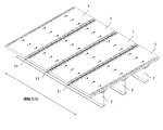
図1は、橋梁の床版としてプレキャスト部材1が主桁2上に配置された状態を示す部分斜視図である。本実施形態では、例としてプレキャスト部材1が橋梁の床版に利用される場合について説明する。図1に示すように、橋梁の床版をプレキャスト部材1によって構築する場合、コンクリート製のプレキャスト部材1を主桁2上に複数(図では部分的に5つ)並べ、隣接するプレキャスト部材1同士を連結するとともに、プレキャスト部材1を主桁2に固定する。通常、主桁2は橋軸方向に延在するよう配置されるので、図1ではプレキャスト部材1が橋軸方向に並べられ、橋軸方向において連結されているが、これに代えて(あるいはこれに加えて)橋軸直角方向にプレキャスト部材1を並べ、橋軸直角方向において連結してもよい。
FIG. 1 is a partial perspective view showing a state in which a
橋梁の床版として用いられるプレキャスト部材1は、図1に示すように、平面視長方形の板状を呈しており、従来と同様にあらかじめ工場や製造ヤードで製作される。その製作方法も略従来と同様であって、所定の型枠内に必要な鉄筋を配置し、所定強度のコンクリートを打設し、十分養生した後に脱型して製作される。従来と異なるのは、プレキャスト部材1のうち他のプレキャスト部材1と連結する面(以下、「継手端面11」という。)にエンドプレート12が配置され、このエンドプレート12が内部に配筋された鉄筋13に固定される点である。
As shown in FIG. 1, a
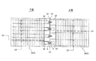
図2はプレキャスト部材1aとプレキャスト部材1bが連結された状態を示す部分断面図であり、図3はその平面図である。図2や図3に示すように、プレキャスト部材1aとプレキャスト部材1bは、それぞれの継手端面11が突き合わされて連結されている。また、図2に示すように、プレキャスト部材1aとプレキャスト部材1bそれぞれの継手端面11にはエンドプレート12が配置されている。このエンドプレート12は板状を呈しており、エンドプレート12の片面が継手端面11に接触している。エンドプレート12の材質としては、曲げ応力に対して比較的抵抗力のあるものが望ましく、例えば鋼製とすることができる。
FIG. 2 is a partial cross-sectional view showing a state where the
図2に示すように、エンドプレート12はプレキャスト部材1内部に配筋された鉄筋13の端部に固定される。ここで固定する目的は、供用後、鉄筋13が負担する曲げモーメントを確実にエンドプレート12に伝達するためである。従って、曲げモーメントを伝達することができれば、エンドプレート12と鉄筋13(の端部)との固定手段は任意に選択することが可能で、例えば、鉄筋13の端部をエンドプレート12に溶接するスタッド溶接や、エンドプレート12にナット4を溶接しこのナットに鉄筋13を固定する手段、など種々の手段を選択することができる。なお、エンドプレート12を固定する鉄筋13は、継手端面11に対して略直交(直交含む)して配置されるものであって、主筋、配力筋の別を指定するものではない。プレキャスト部材1は版であり、たとえ配力筋であっても曲げモーメントを負担することがあるので、必要に応じてすなわちプレキャスト部材1の連結方向に応じて、配力筋とエンドプレート12を連結し、あるいは主筋とエンドプレート12を連結する。
As shown in FIG. 2, the
プレキャスト部材1aとプレキャスト部材1bとの連結は、それぞれの継手端面11に設けられたエンドプレート12同士を突き合わせ(重ね合わせ)て、ボルト3で接合することによって行われる。そのため、エンドプレート12にはボルト3を挿入するためのボルト挿入孔(図示しない)が設けられている。当然ながら、プレキャスト部材1aの継手端面11とプレキャスト部材1bの継手端面11を突き合わせた際、つまり、プレキャスト部材1aのエンドプレート12とプレキャスト部材1bのエンドプレート12を突き合わせた際には、双方のボルト挿入孔は一致し、ボルト3を貫通させることができる。
The connection between the
図2ではエンドプレート12の幅方向(プレキャスト部材1の肉厚方向のことで、図2では上下方向)に2箇所のボルト挿入孔を設けているが、幅方向に1箇所だけボルト挿入孔を設けることも、あるいは3箇所以上とすることも可能で、プレキャスト部材1の部材厚に応じて適宜設計することができる。同様に、図3ではエンドプレート12の長手方向(プレキャスト部材1の幅方向のことで、図3では上下方向)に4箇所のボルト挿入孔を設けているが、長手方向も1箇所あるいは3箇所以上とすることが可能で、プレキャスト部材1の部材幅に応じて適宜設計することができる。またエンドプレート12は、図3に示すように、継手端面11に連続した「1枚もの」を配置することもできるし、ボルト3を配置するところのみ断続的に(例えば図3では4箇所に分けて)配置することもできる。
In FIG. 2, two bolt insertion holes are provided in the width direction of the end plate 12 (the thickness direction of the
図4は、プレキャスト部材1aとプレキャスト部材1bが連結された状態を示す斜視図である。この図に示すように、プレキャスト部材1には箱抜き部14を設けることができる。この箱抜き部14は、エンドプレート12に設けられたボルト挿入孔の周辺部であって、エンドプレート12の背面側(エンドプレート12の部材本体側)に設けられ、ボルト3の固定(接合)作業に必要な空間を提供している。なお、ボルト挿入孔がプレキャスト部材1の外側にあって、ボルト3の接合作業が可能な場合(例えば、図5(a)や図7(b)のような場合)には、必ずしも箱抜き部14を設ける必要はない。
FIG. 4 is a perspective view showing a state in which the
ボルト3の接合作業(すなわち、ボルト3とナット4の締め付け作業)は箱抜き部14の空間内で行われることから、箱抜き部14の一部(図4では上方)は開放されている。この開放された箇所(以下、「開口部」という。)が設けられることによって、ボルト3やナット4付近まで手や治具(工具)を持っていくことが可能となり、ボルト3の接合作業が極めて容易となる。
Since the joining operation of the bolt 3 (that is, the fastening operation of the
箱抜き部14はプレキャスト部材1の強度に対して寄与しないため、できるだけ小さな空間とすることが望ましく、図4のように箱抜き部14と箱抜き部14の間に隔壁15を形成して、ボルト3の周辺のみに独立して(連続せずに)設けられる箱抜き部14とすると好適である。箱抜き部14の開口部が小さければ、プレキャスト部材1を連結した後も箱抜き部14を空洞のままとすることもできるが、図5(b)に示すように、箱抜き部14の内部に補強材を充填することもできる。この補強材には、硬化後に適切な強度を発揮するとともに硬化速度が速く、さらに硬化後の収縮率が小さい無収縮性の材料が適しており、例としては短繊維で補強された無収縮性の超速硬モルタルが挙げられる。箱抜き部14の内部に充填された補強材は、圧縮力に対して貢献することができるので好適である。
Since the
図4に示すように、箱抜き部14の開口部及び隔壁15の上面を、プレキャスト部材1の本体面よりもやや窪んだ高さで(図4ではやや低く)形成することができる。この場合、プレキャスト部材1aとプレキャスト部材1bの継手部において、やや窪んだ凹形状の箇所(以下、「凹部」という。)ができるが、この凹部に嵌合する嵌合板16(図5(c)(d))を設置することができる。あるいは箱抜き部14に充填する補強材を連続して打設することによって、凹部の段差は解消することもできる。嵌合板16が設置された箱抜き部14内には、補強材を充填してもよいし(図5(c))、補強材は充填せずにそのままの状態とすることもできる(図5(d))。一時的に仮覆工する場合など、一旦図5(d)の状態(補強材を充填しない状態)としておき、後に図5(c)の状態(補強材を充填した状態)とするなど、状況に応じて適宜選択することができる。
As shown in FIG. 4, the opening of the
なお、図4では箱抜き部14の開口部がプレキャスト部材1の上面側に設けられているが、これに限らずプレキャスト部材1の下面側に箱抜き部14の開口部を設けることもできる。ただしこの場合、箱抜き部14の内部に補強材を充填するための型枠が必要となりやや作業性が劣るものの、プレキャスト部材1の上面側においては、ボルト3の接合作業等に影響されることなく効率的に作業できるという効果がある。
In FIG. 4, the opening of the
本願発明は、連結された一方のプレキャスト部材1(例えば、プレキャスト部材1a、図4)に生ずる曲げモーメントを、他方のプレキャスト部材1(例えば、プレキャスト部材1b、図4)に伝達させるものである。橋梁床版のように、曲げモーメントが生じるコンクリート製の部材では、おもに部材中の鉄筋13が曲げモーメントを負担する。すなわち、プレキャスト部材1間で曲げモーメントを伝達するには、鉄筋13が負担する曲げモーメントを伝達することが効果的である。従って、本願発明では、鉄筋13とエンドプレート12を連結する構造とした。
In the present invention, a bending moment generated in one connected precast member 1 (for example,
一方、プレキャスト部材1aの鉄筋13が負担する曲げモーメントを、プレキャスト部材1aのエンドプレート12に伝達できたとしても、この曲げモーメントがプレキャスト部材1bのエンドプレート12に伝達されなければ部材間で曲げモーメントは伝達されない。つまり、曲げモーメントに対応して双方のエンドプレート12が離れて(開いて)いくような構造では、プレキャスト部材1間で曲げモーメントは伝達されない。そのため、ボルト3とナット4によって、プレキャスト部材1aとプレキャスト部材1bのエンドプレート12双方を締め付ける。
On the other hand, even if the bending moment borne by the reinforcing
図6は、プレキャスト部材1間の継手部に生ずる断面力を説明するためのモデル図であり、図6(a)は断面力のうち曲げモーメントを、図6(b)は断面力のうちせん断力を説明するものである。一般的に、橋梁床版のように鉛直下向きの荷重が卓越して作用する場合、スパン中央部を下方に曲げようとする曲げモーメント(以下、「正曲げM(+)」という。)の方が大きくなり、スパン中央部を上方に曲げようとする曲げモーメント(以下、「負曲げM(−)」という。)は小さくなる。なお図6(a)では、正曲げM(+)を実線で、負曲げM(−)を破線で示している。継手部に正曲げM(+)が生ずると、図6(a)にも示すように、中立軸を境に部材上部が圧縮域となり、部材下部が引張域となる。つまり、図6(a)の下側鉄筋13には引張力Pが作用し、双方のエンドプレート12を下方で引き離そうとする。
6A and 6B are model diagrams for explaining the cross-sectional force generated in the joint portion between the
エンドプレート12が開いてしまうとその分曲げモーメントは伝達されなくなるので、双方のエンドプレート12が同じように挙動するように、つまり双方のエンドプレート12が接触した状態を維持するように、ボルト3とナット4による締め付け力(ボルト軸力N)が与えられる。言い換えれば、ボルト軸力Nは継手部に生ずる曲げモーメントに対抗するものであるから、ボルト軸力Nの大きさもさることながら、その設置位置が重要であり、中立軸から引張側により離れた位置に設置した方が効果的となる。図6(a)で説明すれば、正曲げM(+)に対抗する場合は中立軸よりも下側にボルト3を設置した方が、負曲げM(−)に対抗する場合は中立軸よりも上側にボルト3を設置した方が効果的となる。また、双方のエンドプレート12が接触した状態が維持されれば、曲げ圧縮力が生じた場合にこれを確実に部材間で伝達することができる。なお、ボルト3を設置した位置よりもさらに引張側の領域においては、エンドプレート12自身によって曲げモーメントに対抗することができる。そのため、前記したようにエンドプレート12の材質としては、曲げ応力に対して比較的抵抗力のあるものが望ましい。
When the
このように、ボルト3の設置位置は中立軸(図6(a))からできるだけ離れた位置とすることが望ましいものの、その設置位置に関しては、種々の条件やエンドプレート12の曲げ強度などを総合的に勘案して適宜設計する。一般的に橋梁床版の場合、前記した理由から正曲げM(+)が大きく負曲げM(−)は小さくなるので、例えば、正曲げM(+)に対抗するボルト3は中立軸から離して配置し、負曲げM(−)に対抗するボルト3は中立軸からあまり離さずに配置するなど、状況に応じて柔軟に設計することができる。
As described above, it is desirable that the installation position of the
さらに例示すれば、小さな曲げモーメント(図6(a)では負曲げM(−)とした)が作用することがあらかじめ分かっている継手部においては、図7(a)に示すように、中立軸付近に1本(断面あたり)だけボルト3を設置することもできる。一方、大きな曲げモーメント(図6(a)では正曲げM(+)とした)が作用する継手部においては、図7(b)に示すように、エンドプレート12の一部をプレキャスト部材1の肉厚方向外側に突出させて、その突出部分(以下、「プレート突出部」という。)に設けられたボルト挿入孔に1本(断面あたり)だけボルト3を設置することができる。あるいは、大きな曲げモーメントである正曲げM(+)と小さな曲げモーメントである負曲げM(−)の両方が作用する継手部においては、図7(c)に示すように、中立軸付近とプレート突出部の2箇所(断面あたり)にボルト3を設置することができる。
Further, for example, in a joint portion where a small bending moment (denoted as negative bending M (−) in FIG. 6A) is known to act in advance, as shown in FIG. Only one bolt 3 (per section) can be installed in the vicinity. On the other hand, in a joint portion where a large bending moment (the positive bending M (+) in FIG. 6A) acts, a part of the
エンドプレート12をプレキャスト部材1の肉厚方向外側に突出させて、このプレート突出部にボルト3を設置すると、中立軸から大きく離れるため構造上は有利となるが、橋梁完成後にもエンドプレート12の一部やボルト3等が露出する。なお、エンドプレート12をプレキャスト部材1の肉厚方向の両方の外側に突出させて、つまりプレキャスト部材1の両側にプレート突出部を設け、それぞれでボルト3接合することもできる。橋梁床版の場合、プレキャスト部材1の両側にプレート突出部があると供用後に障害となってしまうが、土留め用プレキャスト版など他の部材として利用する場合には採用できる場合もある。
If the
(使用例)
橋梁床版として使用するプレキャスト部材1の使用例について、以下説明する。
工場にて、コンクリート製のプレキャスト部材1を製作する。具体的には以下のとおりである。
所定の型枠内に必要な鉄筋13を配置し、継手端面11に位置するようにエンドプレート12を配置し、スタッド溶接により鉄筋13の端部をエンドプレート12に固定する。なお、エンドプレート12には、所定位置に所定数だけのボルト挿入孔があらかじめ設けられている。次に、所定位置及び所定数の箱抜き部14が形成されるように、型枠内で箱抜き工を実施する。最後に型枠内に所定強度のコンクリートを打設し、十分養生した後に脱型して、コンクリート製のプレキャスト部材1が完成される。ここまでの工程を所定回数繰り返し、必要な数量のコンクリート製のプレキャスト部材1を製作する。
以上、製作された必要数のプレキャスト部材1は、輸送車に載せられて工場から出荷される。
現場では主桁2が構築されており、その主桁2上にプレキャスト部材1を並べていく。隣接するプレキャスト1部材同士は、継手部において双方連結される。具体的には、以下のとおりである。
隣接するプレキャスト部材1が対向する面である継手端面11同士を突き合わせ、つまりエンドプレート12同士を突き合わせて、両者のボルト挿入孔の位置合わせを行いながら、プレキャスト部材1の位置を調整していく。箱抜き部14の開口部から手を入れてボルト3をボルト挿入孔に挿入し、箱抜き部14の空間内でボルト3とナット4の仮締めを行う。次に、工具等を開口部から箱抜き部14内に入れてボルト3とナット4の本締めを行う。全てのボルト3を接合し終えたら、箱抜き部14内に短繊維で補強された無収縮性の超速硬モルタル(あるいは短繊維を含有しない無収縮性の超速硬モルタル)等を充填し、所定期間養生を行う。養生中は、継手部に形成された凹部に嵌合板16を設置し、車両等の通行を可能とするとよい。一方、仮覆工する場合は、継手部に形成された凹部に嵌合板16を設置するだけで箱抜き部14内への補強材充填を省略してもよい。
(Example of use)
The usage example of the
The
Necessary reinforcing
As described above, the required number of
The
The positions of the
[その他の実施形態]
本願発明のプレキャスト部材の継手構造とコンクリート製プレキャスト部材は、2つのプレキャスト部材1を突き合わせて連結する場合に限らず、図8に示すように、一つの継手部において3つ以上のプレキャスト部材1(図8では1a、1b、1cの3つ)を連結する場合でも利用することができる。なおこの場合であっても、エンドプレート12の配置や、エンドプレート12と鉄筋13の固定、ボルト3の設置位置、箱抜き部14の設置、補強材充填の有無、あるいはこれら構造による作用については前記した[実施形態]と同様である。
[Other Embodiments]
The joint structure of the precast member and the concrete precast member according to the present invention are not limited to the case where the two
本願発明のプレキャスト部材の継手構造とコンクリート製プレキャスト部材は、橋梁の床版の分割プレキャスト部材限らず、都市トンネルのシールド工法で用いられるセグメント、大深度土留め工に用いられる土留め用プレキャスト版、あるいは大断面のボックスカルバートなどにも応用することができる。 The joint structure of the precast member of the present invention and the precast member made of concrete are not limited to the split precast member of the bridge floor slab, the segment used in the shield method of the city tunnel, the precast plate for earth retaining used for deep earth retaining work, Alternatively, it can be applied to a box culvert with a large cross section.
1 プレキャスト部材
1a 連結される一方のプレキャスト部材
1b 連結される他方のプレキャスト部材
2 主桁
3 ボルト
4 ナット
11 継手端面
12 エンドプレート
13 鉄筋
14 箱抜き部
15 隔壁
16 嵌合板
N ボルト軸力
P 引張力
DESCRIPTION OF
Claims (7)
前記継手部で対向する前記プレキャスト部材の継手端面それぞれに、エンドプレートが配置され、
前記エンドプレートはプレキャスト部材内部の鉄筋に固定され、かつそれぞれのエンドプレートには1又は2以上のボルト挿入孔が設けられ、
前記継手部で対向する前記エンドプレート同士を突き合わせるとともに、前記ボルト挿入孔に挿入したボルトで固定することによって、プレキャスト部材同士が連結されることを特徴とするプレキャスト部材の継手構造。 In the structure of the joint where two or more concrete precast members are connected,
An end plate is disposed on each joint end surface of the precast member facing the joint portion,
The end plate is fixed to a reinforcing bar inside the precast member, and each end plate is provided with one or more bolt insertion holes,
A joint structure of precast members, wherein the end plates facing each other at the joint portion are abutted with each other and fixed by bolts inserted into the bolt insertion holes.
プレキャスト部材のうちエンドプレートのボルト挿入孔周辺部に、ボルト固定作業が可能な空間を形成する箱抜き部が設けられたことを特徴とするプレキャスト部材の継手構造。 In the joint structure of the precast member according to claim 1,
A joint structure for a precast member, wherein a box opening portion for forming a space in which a bolt can be fixed is provided around a bolt insertion hole of an end plate of the precast member.
連結されたプレキャスト部材の箱抜き部に、補強材を充填することを特徴とするプレキャスト部材の継手構造。 In the joint structure of the precast member according to claim 2,
A joint structure for a precast member, wherein the box opening portions of the connected precast members are filled with a reinforcing material.
エンドプレートの一部がプレキャスト部材の肉厚方向の外側に突出するとともに、このエンドプレートの突出部分にボルト挿入孔が設けられ、
前記エンドプレートの突出部分に設けられたボルト挿入孔に挿入したボルトで、継手部で対向する前記エンドプレート同士を固定することを特徴とするプレキャスト部材の継手構造。 In the joint structure of the precast member according to any one of claims 1 to 3,
A part of the end plate protrudes outward in the thickness direction of the precast member, and a bolt insertion hole is provided in the protruding portion of the end plate,
A joint structure for a precast member, wherein the end plates facing each other at a joint portion are fixed with bolts inserted into bolt insertion holes provided in protruding portions of the end plates.
連結される他のプレキャスト部材と対向する継手端面に配置され、かつ部材内の鉄筋に固定されたエンドプレートを備え、
前記エンドプレートには、連結ボルトを挿入できる1又は2以上のボルト挿入孔が設けられたことを特徴とするコンクリート製プレキャスト部材。 In a concrete precast member used by connecting two or more,
An end plate disposed on the joint end face facing the other precast member to be connected, and fixed to the reinforcing bar in the member;
A concrete precast member, wherein the end plate is provided with one or more bolt insertion holes into which connection bolts can be inserted.
エンドプレートのボルト挿入孔周辺部に、ボルト固定作業が可能な空間を形成する箱抜き部が設けられたことを特徴とするコンクリート製プレキャスト部材。 In the concrete precast member according to claim 5,
A concrete precast member characterized in that a box opening portion for forming a space in which a bolt can be fixed is provided around a bolt insertion hole in an end plate.
エンドプレートの一部がプレキャスト部材の肉厚方向の外側に突出するとともに、このエンドプレートの突出部分にボルト挿入孔が設けられたことを特徴とするコンクリート製プレキャスト部材。 In the concrete precast member according to claim 5 or 6,
A concrete precast member characterized in that a part of the end plate protrudes outward in the thickness direction of the precast member, and a bolt insertion hole is provided in a protruding portion of the end plate.
Priority Applications (1)
| Application Number | Priority Date | Filing Date | Title |
|---|---|---|---|
| JP2010221486A JP2012077471A (en) | 2010-09-30 | 2010-09-30 | Joint structure of precast members and concrete precast members |
Applications Claiming Priority (1)
| Application Number | Priority Date | Filing Date | Title |
|---|---|---|---|
| JP2010221486A JP2012077471A (en) | 2010-09-30 | 2010-09-30 | Joint structure of precast members and concrete precast members |
Publications (1)
| Publication Number | Publication Date |
|---|---|
| JP2012077471A true JP2012077471A (en) | 2012-04-19 |
Family
ID=46238035
Family Applications (1)
| Application Number | Title | Priority Date | Filing Date |
|---|---|---|---|
| JP2010221486A Pending JP2012077471A (en) | 2010-09-30 | 2010-09-30 | Joint structure of precast members and concrete precast members |
Country Status (1)
| Country | Link |
|---|---|
| JP (1) | JP2012077471A (en) |
Cited By (8)
| Publication number | Priority date | Publication date | Assignee | Title |
|---|---|---|---|---|
| KR101194482B1 (en) | 2012-05-08 | 2012-10-24 | (주)홍지디씨에스 | The steel systhesis beam and the method threreof |
| JP2015105562A (en) * | 2013-12-03 | 2015-06-08 | 公益財団法人鉄道総合技術研究所 | Aseismic reinforcement method for rigid-frame viaduct arranging beams in intermediate layer |
| JP2019078115A (en) * | 2017-10-26 | 2019-05-23 | 鹿島建設株式会社 | Concrete precast floor slab and joint method |
| JP2019513920A (en) * | 2016-04-08 | 2019-05-30 | ヴォッベン プロパティーズ ゲーエムベーハーWobben Properties Gmbh | Connection body, wind power generator-towering segment, and connection method of two wind power generators-towering segment |
| KR102230785B1 (en) * | 2020-05-13 | 2021-03-22 | (주)렉스코 | Construction method of PC slab for transform and correction manufactured possible modification of production tolerance |
| CN112942678A (en) * | 2021-01-26 | 2021-06-11 | 江西龙正科技发展有限公司 | Novel ultra-high strength concrete UHPC light composite beam |
| KR102269357B1 (en) * | 2020-12-24 | 2021-06-28 | (주) 대현이엔씨 | Rock Shed Structure |
| JP2021147884A (en) * | 2020-03-19 | 2021-09-27 | 鹿島建設株式会社 | Floor slab joint method and floor slab renewal method |
Citations (6)
| Publication number | Priority date | Publication date | Assignee | Title |
|---|---|---|---|---|
| JPS5429625Y1 (en) * | 1975-05-19 | 1979-09-20 | ||
| JPS62143800U (en) * | 1986-03-03 | 1987-09-10 | ||
| JPS63126499U (en) * | 1987-02-10 | 1988-08-18 | ||
| JP2001270765A (en) * | 2000-03-29 | 2001-10-02 | Fujikawa Kenzai Kogyo Kk | Short fiber-mixed non-shrinkage middle-lightweight cement mortar for method for packing in bolt box and method for packing into bolt box using short fiber-mixed non-shrinkage middle-lightweight cement mortar |
| JP2003082997A (en) * | 2001-09-11 | 2003-03-19 | Nippon Steel Corp | Concrete infilling steel segment structure |
| JP2003097196A (en) * | 2001-09-21 | 2003-04-03 | Tokyo Electric Power Co Inc:The | Composite segment in pipe embedment method |
-
2010
- 2010-09-30 JP JP2010221486A patent/JP2012077471A/en active Pending
Patent Citations (6)
| Publication number | Priority date | Publication date | Assignee | Title |
|---|---|---|---|---|
| JPS5429625Y1 (en) * | 1975-05-19 | 1979-09-20 | ||
| JPS62143800U (en) * | 1986-03-03 | 1987-09-10 | ||
| JPS63126499U (en) * | 1987-02-10 | 1988-08-18 | ||
| JP2001270765A (en) * | 2000-03-29 | 2001-10-02 | Fujikawa Kenzai Kogyo Kk | Short fiber-mixed non-shrinkage middle-lightweight cement mortar for method for packing in bolt box and method for packing into bolt box using short fiber-mixed non-shrinkage middle-lightweight cement mortar |
| JP2003082997A (en) * | 2001-09-11 | 2003-03-19 | Nippon Steel Corp | Concrete infilling steel segment structure |
| JP2003097196A (en) * | 2001-09-21 | 2003-04-03 | Tokyo Electric Power Co Inc:The | Composite segment in pipe embedment method |
Cited By (9)
| Publication number | Priority date | Publication date | Assignee | Title |
|---|---|---|---|---|
| KR101194482B1 (en) | 2012-05-08 | 2012-10-24 | (주)홍지디씨에스 | The steel systhesis beam and the method threreof |
| JP2015105562A (en) * | 2013-12-03 | 2015-06-08 | 公益財団法人鉄道総合技術研究所 | Aseismic reinforcement method for rigid-frame viaduct arranging beams in intermediate layer |
| JP2019513920A (en) * | 2016-04-08 | 2019-05-30 | ヴォッベン プロパティーズ ゲーエムベーハーWobben Properties Gmbh | Connection body, wind power generator-towering segment, and connection method of two wind power generators-towering segment |
| JP2019078115A (en) * | 2017-10-26 | 2019-05-23 | 鹿島建設株式会社 | Concrete precast floor slab and joint method |
| JP2021147884A (en) * | 2020-03-19 | 2021-09-27 | 鹿島建設株式会社 | Floor slab joint method and floor slab renewal method |
| JP7316243B2 (en) | 2020-03-19 | 2023-07-27 | 鹿島建設株式会社 | Floor slab joining method, floor slab renewal method |
| KR102230785B1 (en) * | 2020-05-13 | 2021-03-22 | (주)렉스코 | Construction method of PC slab for transform and correction manufactured possible modification of production tolerance |
| KR102269357B1 (en) * | 2020-12-24 | 2021-06-28 | (주) 대현이엔씨 | Rock Shed Structure |
| CN112942678A (en) * | 2021-01-26 | 2021-06-11 | 江西龙正科技发展有限公司 | Novel ultra-high strength concrete UHPC light composite beam |
Similar Documents
| Publication | Publication Date | Title |
|---|---|---|
| JP2012077471A (en) | Joint structure of precast members and concrete precast members | |
| CN107524234B (en) | Connecting beam splitting structure of steel plate concrete shear wall and manufacturing method | |
| JP6375079B1 (en) | Joint structure of precast composite floor slab perpendicular to the bridge axis and its construction method | |
| JP5525489B2 (en) | Concrete floor slab joint structure | |
| JP4740029B2 (en) | Manufacturing method of floor slab or lining board | |
| KR100609184B1 (en) | Joint Structure of Precast Concrete Beam and Column Unit | |
| JP2004285738A (en) | Box girder bridge structure and method of constructing the same | |
| JP2009281066A (en) | Building structure using composite structural beam having pc structure on its ends | |
| JP2007262824A (en) | Detachable dry joining structure of precast floor slab | |
| JP2008266910A (en) | Projection structure of anchorage or deviator of tendon, and construction method therefor | |
| JP5386379B2 (en) | Precast slab joints in bridges | |
| JP2010261270A (en) | Composite structure and method for constructing composite structure building | |
| KR101458435B1 (en) | Half precast concrete column manufacturing method using saddle-type ties and dual hoops and constructing method using the same | |
| JP7158231B2 (en) | Composite column, bridge pier using same, construction method | |
| JP2014105547A (en) | Structure for fixing precast floor slab | |
| KR102004854B1 (en) | Aseismatic Reinforcement Steel Frame with Anchor Plate and Aseismatic Reinforcement Method using thereof | |
| KR101583401B1 (en) | The continuous hybrid girder consist of concrete block and steel block which is can add prestress by gap difference between top and bottom of connection face of blocks | |
| KR101426155B1 (en) | The hybrid rahmen structure which can add prestress on steel girder of horizontal member by gap difference of connection face between vertical member and steel girder of horizontal member | |
| JP4954226B2 (en) | Prestressed concrete structure | |
| JP2016044494A (en) | Construction method of foundation | |
| JP3981688B2 (en) | Joint structure and composite structure of steel beam and reinforced concrete column | |
| JP2006169730A (en) | Concrete bridge girder and method of forming the same | |
| JP4293696B2 (en) | Construction method of composite floor slab bridge | |
| JP2009108500A (en) | Precast beam construction method, precast beam, precast beam joint structure, and building | |
| JP2017025680A (en) | Connection structure of precast concrete beam end and precast concrete beam column frame |
Legal Events
| Date | Code | Title | Description |
|---|---|---|---|
| A621 | Written request for application examination |
Free format text: JAPANESE INTERMEDIATE CODE: A621 Effective date: 20130531 |
|
| A977 | Report on retrieval |
Free format text: JAPANESE INTERMEDIATE CODE: A971007 Effective date: 20131226 |
|
| A131 | Notification of reasons for refusal |
Free format text: JAPANESE INTERMEDIATE CODE: A131 Effective date: 20140107 |
|
| A02 | Decision of refusal |
Free format text: JAPANESE INTERMEDIATE CODE: A02 Effective date: 20140430 |