JP2012013341A5 - - Google Patents
Download PDFInfo
- Publication number
- JP2012013341A5 JP2012013341A5 JP2010151563A JP2010151563A JP2012013341A5 JP 2012013341 A5 JP2012013341 A5 JP 2012013341A5 JP 2010151563 A JP2010151563 A JP 2010151563A JP 2010151563 A JP2010151563 A JP 2010151563A JP 2012013341 A5 JP2012013341 A5 JP 2012013341A5
- Authority
- JP
- Japan
- Prior art keywords
- chamber
- cooling
- heat treatment
- cooling chamber
- workpiece
- Prior art date
- Legal status (The legal status is an assumption and is not a legal conclusion. Google has not performed a legal analysis and makes no representation as to the accuracy of the status listed.)
- Granted
Links
Images
Description
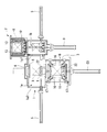
図2に戻り、加熱室2は、被処理物Xの加熱処理を行う円筒形状の部屋であり、各加熱用昇降室1bの上方に設置されている。つまり、本実施形態の多室型熱処理装置S1は、2つの加熱室2を備えている。なお、加熱室2は、被処理物Xに対して加熱処理という処理(熱処理)を行うものであり、本発明の熱処理室であり、本発明における冷却室と異なる他の処理室に相当するものである。
これらの加熱室2には、ヒータ13が設置されており、当該ヒータ13が発熱することによって被処理物Xが加熱処理される。なお、ヒータ13としては、ニッケルクロム(Ni−Cr)、モリブデン(Mo)あるいは黒鉛を発熱体とする電熱ヒータや、高周波電力にて加熱を行うヒータ等を用いることができる。
Returning to FIG. 2, the
In these
再び図2に戻り、冷却室3は、液体粒子であるミストの潜熱により被処理物の冷却を行う熱処理室であり、上述のように中間搬送室1の中央室1aの下方に接続されている。
冷却室3の内部には、冷却室3内にミストを噴霧する複数のノズル16と、これらのノズル16にミストとなる冷却液を案内する複数のヘッダ管17とが設置されている。
Returning to FIG. 2 again, the cooling chamber 3 is a heat treatment chamber that cools an object to be processed by the latent heat of mist that is liquid particles, and is connected below the
Inside the cooling chamber 3, a plurality of
また、図4に示すように、冷却室3には、冷却室3の内部を真空引きするための冷却室用真空ポンプ20が接続されている。
さらに、冷却室3には、冷却室3内に冷却ファン21が接続されており、ガス供給装置11から雰囲気形成ガスを冷却室3内に供給し、さらに冷却ファン21を駆動して冷却室3内の雰囲気形成ガスを熱交換器18c、ヘッダ管17及びノズル16を介して循環させることによって、被処理物Xをガス冷却することも可能に構成されている。
As shown in FIG. 4, the cooling chamber 3 is connected to a cooling
Further, a
また、本実施形態の多室型熱処理装置S1では、ガス供給装置11は、被処理物Xの冷却に使用可能な冷却ガスを冷却室3内に送風することによって冷却室3内を乾燥可能とされている。
つまり、本実施形態の多室型熱処理装置S1では、ガス供給装置11を本発明における冷却ガス供給装置として使用し、乾燥手段として機能させることができる。なお、ガス供給装置11を乾燥手段として機能させる場合には、熱交換器18cによる雰囲気形成ガスの冷却は、必ずしも必要なものではない。
なお、本実施形態の多室型熱処理装置S1では、ガス供給装置11は、ヘッダ管17と接続されており、ヘッダ管17及びノズル16を通じて冷却ガスとなる雰囲気形成ガスを冷却室3内に送風する。
Further, in the multi-chamber heat treatment apparatus S1 of the present embodiment, the
That is, in the multi-chamber heat treatment apparatus S1 of this embodiment, the
In the multi-chamber heat treatment apparatus S1 of the present embodiment, the
なお、本実施形態の多室型熱処理装置S1では、冷却室3において液体(冷却液)を扱うため、当該液体が最も供給及び排出しやすい下方に冷却室3が配置されている。そして、図2に示すように、冷却室3の上方に中間搬送室1が接続され、さらには中間搬送室1の上方に加熱室2が接続され、加熱室2と中間搬送室1との間及び冷却室3と中間搬送室1との間において昇降装置9,23を用いて被処理物Xの受渡しを行う。
つまり、本実施形態の多室型熱処理装置S1では、接続される処理室(中間搬送室1、加熱室2及び冷却室3)同士が高さ方向に配置され、接続された処理室間で被処理物Xの受渡しが昇降装置9,23によって行われる。
In the multi-chamber heat treatment apparatus S1 of the present embodiment, since the liquid (cooling liquid) is handled in the cooling chamber 3, the cooling chamber 3 is disposed below the liquid that is most easily supplied and discharged. As shown in FIG. 2, the
That is, in the multi-chamber heat treatment apparatus S1 of the present embodiment, the connected processing chambers (the
なお、熱風供給装置19による冷却室3の乾燥処理に加えてあるいは換えて、ガス供給装置14からヘッダ管17及びノズル16を通じて雰囲気形成ガス(被処理物Xの冷却に使用可能な冷却ガス)を冷却室3内に送風することによって冷却室3の乾燥を行っても良い。
In addition to or instead of the drying process of the cooling chamber 3 by the hot
このように冷却室3の乾燥が行われた後、上蓋6が上蓋昇降装置7によって上昇されると共に昇降装置23によって載置台22が中間搬送室1内に上昇されることによって、冷却処理が完了した被処理物Xが中間搬送室1に搬送される。
その後、加熱処理及び冷却処理が完了し、焼入れ処理が完了した被処理物Xが搬出入扉4から本実施形態の多室型熱処理装置S1の外部に搬出される。
After the cooling chamber 3 is thus dried, the
Thereafter , the heat treatment and the cooling treatment are completed, and the workpiece X for which the quenching treatment is completed is carried out from the carry-in / out door 4 to the outside of the multi-chamber heat treatment apparatus S1 of the present embodiment.
また、本実施形態の多室型熱処理装置S1によれば、接続される処理室(中間搬送室1、加熱室2及び冷却室3)同士が高さ方向に配置され、接続された処理室間で被処理物Xの受渡しが昇降装置9,23によって行われる。
このため、本実施形態の多室型熱処理装置S1は、平面視形状がコンパクトなものとなり、小さい設置面積に設置することができる。また、被処理物Xを下方から支えながら鉛直搬送する機会が増え、被処理物Xを安定して搬送することができる。
Further, according to the multi-chamber heat treatment apparatus S1 of the present embodiment, the connected processing chambers (the
For this reason, the multi-chamber heat treatment apparatus S1 of the present embodiment has a compact plan view shape and can be installed in a small installation area. Also, increasing opportunities for transporting lead straight while supporting the treatment object X from below, it is possible to stably transport an object to be processed X.
また、上記実施形態においては、接続される処理室(中間搬送室1、加熱室2及び冷却室3)同士が高さ方向に配置され、接続された処理室間で被処理物Xの受渡しが昇降装置9,23によって行われる構成について説明した。
しかしながら、本発明はこれに限定されるものではなく、接続される処理室同士を水平に配置し、接続された処理室間における被処理物Xの受渡しを水平搬送によって行っても良い。
Moreover, in the said embodiment, the process chambers (the intermediate |
However, the present invention is not limited to this, and the processing chambers to be connected may be arranged horizontally, and the workpiece X may be transferred between the connected processing chambers by horizontal conveyance.
Priority Applications (6)
| Application Number | Priority Date | Filing Date | Title |
|---|---|---|---|
| JP2010151563A JP5658928B2 (en) | 2010-07-02 | 2010-07-02 | Multi-chamber heat treatment equipment |
| US13/806,159 US20130153547A1 (en) | 2010-07-02 | 2011-07-01 | Multi-chamber heat treatment device |
| KR1020137002397A KR20130045343A (en) | 2010-07-02 | 2011-07-01 | Multi-chamber heat treatment device |
| CN201180031206.5A CN103038593B (en) | 2010-07-02 | 2011-07-01 | Multi-chamber heat treatment device |
| EP11800994.3A EP2589910A4 (en) | 2010-07-02 | 2011-07-01 | Multi-chamber heat treatment device |
| PCT/JP2011/065179 WO2012002532A1 (en) | 2010-07-02 | 2011-07-01 | Multi-chamber heat treatment device |
Applications Claiming Priority (1)
| Application Number | Priority Date | Filing Date | Title |
|---|---|---|---|
| JP2010151563A JP5658928B2 (en) | 2010-07-02 | 2010-07-02 | Multi-chamber heat treatment equipment |
Publications (3)
| Publication Number | Publication Date |
|---|---|
| JP2012013341A JP2012013341A (en) | 2012-01-19 |
| JP2012013341A5 true JP2012013341A5 (en) | 2013-05-02 |
| JP5658928B2 JP5658928B2 (en) | 2015-01-28 |
Family
ID=45402234
Family Applications (1)
| Application Number | Title | Priority Date | Filing Date |
|---|---|---|---|
| JP2010151563A Expired - Fee Related JP5658928B2 (en) | 2010-07-02 | 2010-07-02 | Multi-chamber heat treatment equipment |
Country Status (6)
| Country | Link |
|---|---|
| US (1) | US20130153547A1 (en) |
| EP (1) | EP2589910A4 (en) |
| JP (1) | JP5658928B2 (en) |
| KR (1) | KR20130045343A (en) |
| CN (1) | CN103038593B (en) |
| WO (1) | WO2012002532A1 (en) |
Families Citing this family (11)
| Publication number | Priority date | Publication date | Assignee | Title |
|---|---|---|---|---|
| US9731990B2 (en) * | 2013-05-30 | 2017-08-15 | Johns Manville | Submerged combustion glass melting systems and methods of use |
| JP6515370B2 (en) * | 2014-05-29 | 2019-05-22 | 株式会社Ihi | Cooling device and multi-chamber heat treatment apparatus |
| JP6418830B2 (en) | 2014-07-25 | 2018-11-07 | 株式会社Ihi | Cooling device and multi-chamber heat treatment device |
| JP6418832B2 (en) * | 2014-07-28 | 2018-11-07 | 株式会社Ihi | Conveying device for heat treatment apparatus and heat treatment apparatus |
| JP6297471B2 (en) * | 2014-11-10 | 2018-03-20 | 中外炉工業株式会社 | Heat treatment equipment |
| JP6238498B2 (en) | 2014-11-20 | 2017-11-29 | 株式会社Ihi | Heat treatment device and cooling device |
| JP6596703B2 (en) * | 2015-03-04 | 2019-10-30 | 株式会社Ihi | Multi-chamber heat treatment equipment |
| JP6338314B2 (en) | 2015-05-26 | 2018-06-06 | 株式会社Ihi | Heat treatment equipment |
| JP6721466B2 (en) * | 2016-09-12 | 2020-07-15 | 株式会社Ihi | Heat treatment equipment |
| FR3073937B1 (en) * | 2017-11-21 | 2020-08-14 | Ceritherm | HEAT TREATMENT PLANT FOR THE MANUFACTURE OF INDUSTRIAL PRODUCTS. |
| CN114197056A (en) * | 2022-01-14 | 2022-03-18 | 浙江大学杭州国际科创中心 | Semiconductor material annealing device and annealing method |
Family Cites Families (21)
| Publication number | Priority date | Publication date | Assignee | Title |
|---|---|---|---|---|
| US3403451A (en) * | 1965-03-30 | 1968-10-01 | Fluid Energy Proc & Equipment | Method for drying or treating wet solid and semisolid materials |
| US3886760A (en) * | 1970-09-03 | 1975-06-03 | Stephen Wyden | Method of indirect heat exchange |
| US3953247A (en) * | 1972-11-21 | 1976-04-27 | Prolizenz Ag | Method for heat treatment of material to be worked on, especially of aluminium or magnesium alloys |
| DE4005956C1 (en) * | 1990-02-26 | 1991-06-06 | Siegfried Dipl.-Ing. Dr. 5135 Selfkant De Straemke | |
| JP3310997B2 (en) * | 1991-11-28 | 2002-08-05 | 株式会社日立製作所 | Continuous processing equipment |
| CN1052566C (en) * | 1993-11-05 | 2000-05-17 | 株式会社半导体能源研究所 | Method for processing semiconductor device, apparatus for processing a semiconductor and apparatus for processing semiconductor device |
| JP3490791B2 (en) * | 1994-12-20 | 2004-01-26 | 光洋サーモシステム株式会社 | Multi-chamber heat treatment furnace |
| US6059507A (en) * | 1997-04-21 | 2000-05-09 | Brooks Automation, Inc. | Substrate processing apparatus with small batch load lock |
| JPH11153386A (en) * | 1997-11-25 | 1999-06-08 | Ishikawajima Harima Heavy Ind Co Ltd | Multichamber multi-cooling vacuum furnace |
| JP3820950B2 (en) * | 2001-10-03 | 2006-09-13 | 大同特殊鋼株式会社 | Atmospheric heat treatment furnace and its seasoning method |
| US8530359B2 (en) * | 2003-10-20 | 2013-09-10 | Novellus Systems, Inc. | Modulated metal removal using localized wet etching |
| US7841582B2 (en) * | 2004-06-02 | 2010-11-30 | Applied Materials, Inc. | Variable seal pressure slit valve doors for semiconductor manufacturing equipment |
| US9799536B2 (en) * | 2005-02-07 | 2017-10-24 | Planar Semiconductor, Inc. | Apparatus and method for cleaning flat objects in a vertical orientation with pulsed liquid jet |
| US7845891B2 (en) * | 2006-01-13 | 2010-12-07 | Applied Materials, Inc. | Decoupled chamber body |
| US8124907B2 (en) * | 2006-08-04 | 2012-02-28 | Applied Materials, Inc. | Load lock chamber with decoupled slit valve door seal compartment |
| US20090001057A1 (en) * | 2007-06-29 | 2009-01-01 | Cheng-Hsin Ma | Dual damascene trench depth detection and control using voltage impedance RF probe |
| US20110155192A1 (en) * | 2008-02-27 | 2011-06-30 | Nadeem Ahmad | System and apparatus for automatic built-in vehicle washing and other operations |
| JP2010014290A (en) * | 2008-07-01 | 2010-01-21 | Ihi Corp | Multiple-chamber type heat treat furnace |
| JP2010038531A (en) * | 2008-07-10 | 2010-02-18 | Ihi Corp | Heat treatment device |
| US20100024847A1 (en) * | 2008-08-01 | 2010-02-04 | Breese Ronald G | Semiconductor wafer cleaning with dilute acids |
| JP5203986B2 (en) * | 2009-01-19 | 2013-06-05 | 東京エレクトロン株式会社 | Focus ring heating method, plasma etching method, plasma etching apparatus and computer storage medium |
-
2010
- 2010-07-02 JP JP2010151563A patent/JP5658928B2/en not_active Expired - Fee Related
-
2011
- 2011-07-01 WO PCT/JP2011/065179 patent/WO2012002532A1/en active Application Filing
- 2011-07-01 KR KR1020137002397A patent/KR20130045343A/en active IP Right Grant
- 2011-07-01 US US13/806,159 patent/US20130153547A1/en not_active Abandoned
- 2011-07-01 EP EP11800994.3A patent/EP2589910A4/en not_active Withdrawn
- 2011-07-01 CN CN201180031206.5A patent/CN103038593B/en not_active Expired - Fee Related
Similar Documents
| Publication | Publication Date | Title |
|---|---|---|
| JP2012013341A5 (en) | ||
| JP5658928B2 (en) | Multi-chamber heat treatment equipment | |
| ES2716381T3 (en) | Transport device for thin-walled, hot-walled steel parts | |
| JP5470471B2 (en) | Transport device and transport heat treatment system | |
| KR20200069216A (en) | Temperature adjustment apparatus for high temperature oven | |
| JP2008501232A (en) | Cleaning mask substrate | |
| WO2015024339A1 (en) | Substrate drying device and substrate cleaning system | |
| JP5401015B2 (en) | Continuous firing furnace | |
| KR20140001829U (en) | Thermal processing apparatus | |
| TW201631619A (en) | Inductively-coupled plasma processing device | |
| JP2011066318A (en) | Heat processing apparatus | |
| CN206553575U (en) | A kind of hardware Equipment for Heating Processing | |
| TWI351724B (en) | Annealing apparatus | |
| JP5634127B2 (en) | Heat treatment furnace | |
| CN104131153A (en) | Device for conveniently heating aluminum alloy blank materials | |
| TW200916850A (en) | Cooling device for sheet treated product and heat treatment system mounting the device | |
| JP2004014892A (en) | High-temperature heating apparatus | |
| JP2004063663A (en) | Device for manufacturing semiconductor | |
| JP2016069704A (en) | Heat treatment facility and heat treatment method of cylindrical plate coil | |
| CN104048503A (en) | Circuit board tunnel baking oven | |
| TW202023009A (en) | Temperature adjusting equipment of high-temperature oven for greatly enhancing heating and cooling efficiency of gas and effectively reducing production cost | |
| JP2021009923A (en) | Heat treatment apparatus and heat treatment method | |
| JP6274448B2 (en) | Firing furnace and coating method | |
| CN211079255U (en) | Waste heat recovery device | |
| JP5313772B2 (en) | Heat treatment device with superheated steam |