KR20130045343A - Multi-chamber heat treatment device - Google Patents
Multi-chamber heat treatment device Download PDFInfo
- Publication number
- KR20130045343A KR20130045343A KR1020137002397A KR20137002397A KR20130045343A KR 20130045343 A KR20130045343 A KR 20130045343A KR 1020137002397 A KR1020137002397 A KR 1020137002397A KR 20137002397 A KR20137002397 A KR 20137002397A KR 20130045343 A KR20130045343 A KR 20130045343A
- Authority
- KR
- South Korea
- Prior art keywords
- chamber
- cooling
- heat treatment
- cooling chamber
- processing
- Prior art date
Links
Images


Classifications
-
- F—MECHANICAL ENGINEERING; LIGHTING; HEATING; WEAPONS; BLASTING
- F27—FURNACES; KILNS; OVENS; RETORTS
- F27B—FURNACES, KILNS, OVENS, OR RETORTS IN GENERAL; OPEN SINTERING OR LIKE APPARATUS
- F27B9/00—Furnaces through which the charge is moved mechanically, e.g. of tunnel type; Similar furnaces in which the charge moves by gravity
- F27B9/02—Furnaces through which the charge is moved mechanically, e.g. of tunnel type; Similar furnaces in which the charge moves by gravity of multiple-track type; of multiple-chamber type; Combinations of furnaces
-
- B—PERFORMING OPERATIONS; TRANSPORTING
- B23—MACHINE TOOLS; METAL-WORKING NOT OTHERWISE PROVIDED FOR
- B23K—SOLDERING OR UNSOLDERING; WELDING; CLADDING OR PLATING BY SOLDERING OR WELDING; CUTTING BY APPLYING HEAT LOCALLY, e.g. FLAME CUTTING; WORKING BY LASER BEAM
- B23K10/00—Welding or cutting by means of a plasma
- B23K10/02—Plasma welding
-
- C—CHEMISTRY; METALLURGY
- C21—METALLURGY OF IRON
- C21D—MODIFYING THE PHYSICAL STRUCTURE OF FERROUS METALS; GENERAL DEVICES FOR HEAT TREATMENT OF FERROUS OR NON-FERROUS METALS OR ALLOYS; MAKING METAL MALLEABLE, e.g. BY DECARBURISATION OR TEMPERING
- C21D1/00—General methods or devices for heat treatment, e.g. annealing, hardening, quenching or tempering
- C21D1/06—Surface hardening
- C21D1/09—Surface hardening by direct application of electrical or wave energy; by particle radiation
-
- C—CHEMISTRY; METALLURGY
- C21—METALLURGY OF IRON
- C21D—MODIFYING THE PHYSICAL STRUCTURE OF FERROUS METALS; GENERAL DEVICES FOR HEAT TREATMENT OF FERROUS OR NON-FERROUS METALS OR ALLOYS; MAKING METAL MALLEABLE, e.g. BY DECARBURISATION OR TEMPERING
- C21D1/00—General methods or devices for heat treatment, e.g. annealing, hardening, quenching or tempering
- C21D1/34—Methods of heating
- C21D1/38—Heating by cathodic discharges
-
- C—CHEMISTRY; METALLURGY
- C21—METALLURGY OF IRON
- C21D—MODIFYING THE PHYSICAL STRUCTURE OF FERROUS METALS; GENERAL DEVICES FOR HEAT TREATMENT OF FERROUS OR NON-FERROUS METALS OR ALLOYS; MAKING METAL MALLEABLE, e.g. BY DECARBURISATION OR TEMPERING
- C21D1/00—General methods or devices for heat treatment, e.g. annealing, hardening, quenching or tempering
- C21D1/74—Methods of treatment in inert gas, controlled atmosphere, vacuum or pulverulent material
- C21D1/773—Methods of treatment in inert gas, controlled atmosphere, vacuum or pulverulent material under reduced pressure or vacuum
-
- F—MECHANICAL ENGINEERING; LIGHTING; HEATING; WEAPONS; BLASTING
- F27—FURNACES; KILNS; OVENS; RETORTS
- F27B—FURNACES, KILNS, OVENS, OR RETORTS IN GENERAL; OPEN SINTERING OR LIKE APPARATUS
- F27B17/00—Furnaces of a kind not covered by any preceding group
- F27B17/0016—Chamber type furnaces
-
- F—MECHANICAL ENGINEERING; LIGHTING; HEATING; WEAPONS; BLASTING
- F27—FURNACES; KILNS; OVENS; RETORTS
- F27B—FURNACES, KILNS, OVENS, OR RETORTS IN GENERAL; OPEN SINTERING OR LIKE APPARATUS
- F27B19/00—Combinations of furnaces of kinds not covered by a single preceding main group
- F27B19/04—Combinations of furnaces of kinds not covered by a single preceding main group arranged for associated working
-
- F—MECHANICAL ENGINEERING; LIGHTING; HEATING; WEAPONS; BLASTING
- F27—FURNACES; KILNS; OVENS; RETORTS
- F27B—FURNACES, KILNS, OVENS, OR RETORTS IN GENERAL; OPEN SINTERING OR LIKE APPARATUS
- F27B9/00—Furnaces through which the charge is moved mechanically, e.g. of tunnel type; Similar furnaces in which the charge moves by gravity
- F27B9/06—Furnaces through which the charge is moved mechanically, e.g. of tunnel type; Similar furnaces in which the charge moves by gravity heated without contact between combustion gases and charge; electrically heated
- F27B9/10—Furnaces through which the charge is moved mechanically, e.g. of tunnel type; Similar furnaces in which the charge moves by gravity heated without contact between combustion gases and charge; electrically heated heated by hot air or gas
-
- F—MECHANICAL ENGINEERING; LIGHTING; HEATING; WEAPONS; BLASTING
- F27—FURNACES; KILNS; OVENS; RETORTS
- F27D—DETAILS OR ACCESSORIES OF FURNACES, KILNS, OVENS, OR RETORTS, IN SO FAR AS THEY ARE OF KINDS OCCURRING IN MORE THAN ONE KIND OF FURNACE
- F27D7/00—Forming, maintaining, or circulating atmospheres in heating chambers
- F27D7/02—Supplying steam, vapour, gases, or liquids
-
- F—MECHANICAL ENGINEERING; LIGHTING; HEATING; WEAPONS; BLASTING
- F27—FURNACES; KILNS; OVENS; RETORTS
- F27D—DETAILS OR ACCESSORIES OF FURNACES, KILNS, OVENS, OR RETORTS, IN SO FAR AS THEY ARE OF KINDS OCCURRING IN MORE THAN ONE KIND OF FURNACE
- F27D9/00—Cooling of furnaces or of charges therein
Landscapes
- Engineering & Computer Science (AREA)
- Chemical & Material Sciences (AREA)
- Mechanical Engineering (AREA)
- General Engineering & Computer Science (AREA)
- Physics & Mathematics (AREA)
- Metallurgy (AREA)
- Crystallography & Structural Chemistry (AREA)
- Materials Engineering (AREA)
- Thermal Sciences (AREA)
- Organic Chemistry (AREA)
- Plasma & Fusion (AREA)
- Combustion & Propulsion (AREA)
- Tunnel Furnaces (AREA)
- Heat Treatments In General, Especially Conveying And Cooling (AREA)
- Furnace Details (AREA)
- Physical Or Chemical Processes And Apparatus (AREA)
- Drying Of Solid Materials (AREA)
Abstract
열처리실을 포함한 복수의 처리실을 구비한 다실형 열처리 장치(S1)로서, 액체입자의 잠열에 의해 피처리물을 냉각시키는 열처리실인 냉각실(3)과, 냉각실(3)과 다른 기타의 처리실(1, 2)과, 냉각실(3)의 건조를 행하는 건조 장치(11,19)를 구비한다.A multi-chamber heat treatment apparatus (S1) having a plurality of treatment chambers including a heat treatment chamber, comprising: a cooling chamber (3), which is a heat treatment chamber for cooling a target object by latent heat of liquid particles, and a cooling chamber (3) and other processing chambers. (1, 2) and drying apparatuses 11 and 19 which dry the cooling chamber 3 are provided.
Description
본 발명은, 다실형 열처리 장치에 관한 것이다. 본원은 2010년 7월 2일 일본에 출원된 일본특허출원 2010-151563호에 근거하여 우선권을 주장하고 그 내용을 여기에 원용한다.The present invention relates to a multi-threaded heat treatment apparatus. This application claims priority based on Japanese Patent Application No. 2010-151563 for which it applied to Japan on July 2, 2010, and uses the content here.
종래부터 피처리물인 금속 부품에 대해 담금질 등의 처리를 행할 때에 열처리실을 포함한 복수의 처리실을 가진 다실형 열처리 장치가 이용되고 있다(특허문헌 1 참조).Conventionally, the multi-chamber heat processing apparatus which has several process chambers including a heat processing chamber is used when performing a process of hardening etc. about the metal component which is a to-be-processed object (refer patent document 1).
이 다실형 열처리 장치는 일반적으로 처리실로서, 피처리물을 가열하는 가열실이나, 가열실에서 가열된 피처리물을 냉각시키는 냉각실 등을 가지고 있다.This multi-room type heat treatment apparatus generally has a heating chamber for heating a to-be-processed object, a cooling chamber for cooling the to-be-processed object heated in the heating chamber, and the like.
종래부터 피처리물의 냉각 방법으로서는 가스 냉각과 오일 냉각이 일반적으로 이용되고 있다.Conventionally, gas cooling and oil cooling are generally used as a cooling method of a to-be-processed object.
가스 냉각은, 피처리물에 대해 냉각 가스를 내뿜어 냉각시키는 방법으로서 냉각 가스의 분사량이나 그 분포를 용이하게 조절할 수 있기 때문에 냉각 조절성이 우수한 방법이다.Gas cooling is a method of exhaling cooling gas to a to-be-processed object, and since it is easy to adjust the injection amount and distribution of cooling gas, it is the method of excellent cooling controlability.
오일 냉각은, 피처리물을 냉각유에 대하여 침지시켜 냉각시키는 방법으로서 피처리물과 냉각유의 열전달 효율이 높기 때문에 냉각 효율이 높은 방법이다.Oil cooling is a method of immersing and cooling a to-be-processed object with cooling oil, and since it is high in heat transfer efficiency of a to-be-processed object and a cooling oil, it is a method with high cooling efficiency.
그러나 가스 냉각은 피처리물과 냉각 가스간의 열전달율이 낮기 때문에 냉각 효율이 높지 않다는 문제가 있다. 또 오일 냉각은 피처리물 전체가 냉각유에 침지되기 때문에 미세한 냉각 속도의 조절이 어려워 냉각 조절성이 높지 않다는 문제가 있다.However, gas cooling has a problem that the cooling efficiency is not high because the heat transfer rate between the workpiece and the cooling gas is low. In addition, the oil cooling has a problem that it is difficult to control the minute cooling rate because the whole to be treated is immersed in the cooling oil, the cooling controllability is not high.
전술한 이유 때문에 최근에는 피처리물의 냉각 효율과 냉각 조절성을 양립시키기 위해 냉각실에서 액체 입자의 잠열에 의해 피처리물을 냉각시키는 방법이 제안되어 있다.For the reason mentioned above, in recent years, the method of cooling the to-be-processed object by the latent heat of a liquid particle in a cooling chamber is proposed in order to make the cooling efficiency of a to-be-processed object compatible with a cooling controllability.
액체 입자의 잠열에 의해 피처리물을 냉각시킬 경우에는 냉각실에 액체 입자를 충전(充塡) 혹은 분출하여 피처리물에 액체 입자를 부착시키고 액체 입자가 기화할 때의 잠열을 피처리물로부터 빼앗는다. 그 결과 피처리물이 냉각된다.When the workpiece is cooled by the latent heat of the liquid particles, liquid particles are charged or ejected into the cooling chamber to attach the liquid particles to the workpiece, and the latent heat when the liquid particles vaporize from the workpiece. Take away. As a result, the workpiece is cooled.
상술한 다실형 열처리 장치에서 액체 입자의 잠열에 의해 피처리물을 냉각시키는 방법을 채용할 경우에는 다실형 열처리 장치가 구비한 냉각실에 액체 입자를 충전 혹은 분출할 필요가 있다.When employing the method of cooling the to-be-processed object by the latent heat of liquid particle in the said multi-chamber heat processing apparatus, it is necessary to fill or blow out liquid particle in the cooling chamber with which the multi-chamber heat processing apparatus was equipped.
그러나 다실형 열처리 장치에서 냉각실에 액체 입자를 충전 혹은 분출하면 당연히 피처리물 이외의 냉각실 내벽 등에도 액체 입자가 부착된다. 그 결과 피처리물 이외에 부착된 액체 입자는 피처리물보다 부착 영역의 온도가 낮기 때문에 기화하지 않고 잔존한다.However, in the multi-chamber heat treatment apparatus, when liquid particles are filled or ejected into the cooling chamber, the liquid particles naturally adhere to the inner wall of the cooling chamber other than the workpiece. As a result, the liquid particles adhered to the object other than the object remain without vaporization because the temperature of the attachment region is lower than that of the object.
냉각실 내에 기화하지 않은 액체 입자가 잔존하면 냉각실과 다른 처리실 사이에서 피처리물을 주고받을 때 액체 입자 혹은 액체 입자가 응집된 액체(즉 냉각액)가 다른 처리실을 오염시킨다. 따라서 처리실 사이에서 피처리물을 주고받음에 따라서, 다실형 열처리 장치가 구비한 모든 처리실이 냉각액으로 오염되는 경우도 있다.If the liquid particles which have not been vaporized remain in the cooling chamber, the liquid particles or the liquid in which the liquid particles are agglomerated (ie, the cooling liquid) contaminate other processing chambers when the workpiece is exchanged between the cooling chamber and another processing chamber. Accordingly, as the object to be processed is exchanged between the processing chambers, all the processing chambers provided with the multi-room heat treatment apparatus may be contaminated with the cooling liquid.
예를 들면, 다실형 열처리 장치가 구비한 가열실이 냉각액으로 오염된 경우에는 가열 온도의 저하에 기인하여 피처리물에 산화막이 형성되어 피처리물이 의도치 않게 착색되는 경우가 있다.For example, when the heating chamber with the multi-chamber heat treatment apparatus is contaminated with a cooling liquid, an oxide film is formed on the workpiece due to a decrease in the heating temperature, and the workpiece may be unintentionally colored.
본 발명은, 다실형 열처리 장치에서 냉각실 이외의 다른 처리실이 냉각액으로 오염되는 것을 방지하는 것을 목적으로 한다.An object of the present invention is to prevent contamination of the processing chamber other than the cooling chamber with the cooling liquid in the multi-chamber heat treatment apparatus.
본 발명은, 상기 과제를 해결하기 위한 수단으로서 이하의 구성을 채용한다.This invention adopts the following structures as a means for solving the said subject.
본 발명에 관한 다실형 열처리 장치는, 열처리실을 포함한 복수의 처리실을 구비한 다실형 열처리 장치로서, 액체 입자의 잠열에 의해 피처리물의 냉각을 행하는 상기 열처리실인 냉각실과, 상기 냉각실과 다른 기타의 처리실과, 상기 냉각실의 건조를 행하는 건조 장치를 구비한다.A multi-room heat treatment apparatus according to the present invention is a multi-room heat treatment apparatus including a plurality of treatment chambers including a heat treatment chamber, which is a cooling chamber which is the heat treatment chamber that cools a target object by the latent heat of liquid particles, and the cooling chamber and the other. A drying chamber for drying the processing chamber and the cooling chamber is provided.
또 상기 건조 장치가, 상기 냉각실 내로 열풍을 공급하는 열풍 공급 장치를 구비해도 좋다.Moreover, the said drying apparatus may be equipped with the hot air supply apparatus which supplies hot air to the said cooling chamber.
또 상기 건조 장치가, 상기 피처리물의 냉각에 사용 가능한 냉각 가스를 상기 냉각실 내로 송풍하여 건조를 행하는 냉각 가스 공급 장치를 구비해도 좋다.Moreover, the drying apparatus may be provided with the cooling gas supply apparatus which blows the cooling gas which can be used for cooling the said to-be-processed object into the said cooling chamber, and performs drying.
또 상기 냉각실 내로 상기 액체 입자를 분무하는 노즐과, 상기 노즐에 액체 입자가 되는 냉각액을 안내하는 헤더관을 구비하고, 상기 냉각 가스 공급 장치가 상기 노즐 및 상기 헤더관을 통해 상기 냉각 가스를 상기 냉각실 내로 송풍해도 좋다.And a nozzle for spraying the liquid particles into the cooling chamber, and a header tube for guiding a coolant that becomes liquid particles to the nozzle, wherein the cooling gas supply device supplies the cooling gas through the nozzle and the header tube. You may blow into a cooling chamber.
또 상기 냉각실과 다른 기타의 처리실로서, 상기 피처리물을 가열 처리하는 가열실을 구비해도 좋다.Moreover, you may provide the heating chamber which heat-processes the said to-be-processed object as another processing chamber different from the said cooling chamber.
또 상기 냉각실과 다른 기타의 처리실로서, 상기 가열실과 상기 냉각실 사이에 배치되는 중간 반송실을 구비해도 좋다.Moreover, you may provide the intermediate | middle conveyance chamber arrange | positioned between the said heating chamber and the said cooling chamber as another processing chamber different from the said cooling chamber.
또 상기 냉각실과 다른 기타의 처리실로서, 상기 피처리물에 대한 플라즈마 처리를 행하는 플라즈마 처리실을 구비해도 좋다.In addition, as the processing chamber other than the cooling chamber, a plasma processing chamber which performs a plasma treatment on the target object may be provided.
또 상기 플라즈마 처리실의 내부에 고정 배치됨과 동시에 상기 플라즈마 처리실의 내부에 상기 피처리물이 반입되었을 때 상기 피처리물이 놓이는 도전성 트레이와 접촉하는 전극을 구비해도 좋다.The electrode may be provided fixedly in the plasma processing chamber and in contact with a conductive tray on which the workpiece is placed when the workpiece is loaded into the plasma processing chamber.
또 접속되는 상기 처리실들이 높이 방향으로 배치되고, 접속된 상기 처리실 사이에서 상기 피처리물의 주고받기를 행하는 승강 장치를 구비해도 좋다.Moreover, the said process chambers connected may be arrange | positioned in the height direction, and may be provided with the lifting device which sends and receives the to-be-processed object between connected process chambers.
또 상기 열풍 공급 장치가, 상기 피처리물이 놓인 상기 냉각실 내로 열풍을 공급함으로써 행하는 뜨임(tempering) 처리에 사용 가능해도 좋다.In addition, the hot air supply device may be used for a tempering process performed by supplying hot air into the cooling chamber in which the object to be processed is placed.
본 발명에 의하면, 건조 장치에 의해 냉각실의 건조가 행해진다. 따라서 냉각실과 다른 처리실 사이에서 피처리물을 주고받기에 앞서 냉각실의 건조를 행함으로써 냉각실 내에 잔존하는 냉각액(액체 입자 및 상기 액체 입자가 응집된 액체를 포함한다)이 증발하여 상기 냉각액이 다른 처리실에 유입되는 것을 방지할 수 있다.According to this invention, drying of a cooling chamber is performed by a drying apparatus. Therefore, the coolant remaining in the cooling chamber (including liquid particles and agglomerated liquid particles) is evaporated by drying the cooling chamber before the target object is exchanged between the cooling chamber and the other processing chambers. It can be prevented from entering the processing chamber.
따라서 본 발명에 의하면, 다실형 열처리 장치에서 냉각실 이외의 기타의 처리실이 냉각액으로 오염되는 것을 방지할 수 있게 된다.Therefore, according to the present invention, it is possible to prevent the processing chamber other than the cooling chamber from being contaminated with the cooling liquid in the multi-chamber heat treatment apparatus.
도 1은, 본 발명의 일실시형태에서의 다실형 열처리 장치의 개략 구성을 도시한 평면도이다.
도 2는, 도 1의 A-A선 단면도이다.
도 3은, 도 1의 B-B선 단면도이다.
도 4는, 본 발명의 일실시형태에서의 다실형 열처리 장치의 기능 블럭도이다.
도 5는, 본 발명의 일실시형태에서의 다실형 열처리 장치의 변형예가 구비한 플라즈마 처리실의 단면도이다.BRIEF DESCRIPTION OF THE DRAWINGS It is a top view which shows schematic structure of the multi-room heat processing apparatus in one Embodiment of this invention.
FIG. 2 is a cross-sectional view taken along the line AA of FIG. 1.
3 is a cross-sectional view taken along the line BB of FIG. 1.
4 is a functional block diagram of a multi-chamber heat treatment apparatus in one embodiment of the present invention.
5 is a cross-sectional view of a plasma processing chamber of a modification of the multi-chamber heat treatment apparatus according to the embodiment of the present invention.
이하, 도면을 참조하여 본 발명에 관한 다실형 열처리 장치의 일실시형태에 대해 설명하기로 한다. 이하의 도면에서 각 부재를 인식 가능한 크기로 하기 위해 각 부재의 축척을 적절히 변경하였다.EMBODIMENT OF THE INVENTION Hereinafter, one Embodiment of the multi-chamber heat processing apparatus which concerns on this invention is described with reference to drawings. In the following drawings, the scale of each member is appropriately changed in order to make the size of each member recognizable.
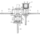
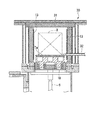
도 1은, 본 실시형태의 다실형 열처리 장치(S1)의 개략 구성을 도시한 평면도이다. 도 2는, 도 1의 A-A선 단면도이다. 도 3은, 도 1의 B-B선 단면도이다. 또 도 4는, 본 실시형태의 다실형 열처리 장치(S1)의 기능 블럭도이다. 도 1~도 3에서는, 도 4에 도시한 구성요소의 일부를 생략하고, 도 4에서는, 도 1~도 3에 도시한 구성요소의 일부를 생략하였다. 도 3에서는, 후술하는 냉각실(3)의 도시를 생략하였다. 도 1 및 도 3에서는, 후술하는 상부덮개(6)가 닫힌 상태를 도시하였다. 또 도 2에서는, 후술하는 상부덮개(6)가 상승한 상태를 도시하였다.FIG. 1: is a top view which shows schematic structure of the multi-chamber heat processing apparatus S1 of this embodiment. 2 is a sectional view taken along the line A-A in Fig. 3 is a cross-sectional view taken along the line B-B in FIG. 1. 4 is a functional block diagram of the polysilicon heat treatment apparatus S1 of this embodiment. In FIG. 1 to FIG. 3, some of the components shown in FIG. 4 are omitted, and in FIG. 4, some of the components shown in FIGS. 1 to 3 are omitted. In FIG. 3, illustration of the
도 1 및 도 4에 도시한 바와 같이, 본 실시형태의 다실형 열처리 장치(S1)는, 금속 부품인 피처리물(X)에 대해 담금질 처리를 하기 위한 열처리 장치이다. 다실형 열처리 장치(S1)는, 중간 반송실(1)(처리실)과 가열실(2)(처리실)과 냉각실(3)(처리실)을 구비하고 있다.As shown to FIG. 1 and FIG. 4, the multi-room heat processing apparatus S1 of this embodiment is a heat processing apparatus for performing a hardening process with respect to the to-be-processed object X which is a metal component. The polysilicon heat treatment apparatus S1 is equipped with the intermediate | middle conveyance chamber 1 (process chamber), the heating chamber 2 (process chamber), and the cooling chamber 3 (process chamber).
중간 반송실(1)은 가열실(2)과 냉각실(3) 사이에 배치되어 있으며 가열실(2)과 냉각실(3) 사이에서 피처리물(X)을 반송하기 위한 방이다. 중간 반송실(1)은 중앙실(1a)과 가열용 승강실(1b)을 가지고 있다. 중간 반송실(1)은, 피처리물(X)을 반송하는 처리를 행한다. 즉, 중간 반송실(1)은 본 발명의 처리실 중 하나로서 기능한다.The intermediate |
중앙실(1a)은, 도 1에 도시한 바와 같이 정팔각형으로 형상이 설정되어 있으며 본 실시형태의 다실형 열처리 장치(S1)에서 처리되는 모든 피처리물(X)이 통과하는 방이다.As shown in FIG. 1, the
중앙실(1a)은 8개의 측벽(1a1)~(1a8)을 구비하고 있다. 측벽(1a1)~(1a8) 중 하나인 측벽(1a1)에는 본 실시형태의 다실형 열처리 장치(S1)로의 출입구가 되는 반출입문(4)이 설치되어 있다. 피처리물(X)은 반출입문(4)을 통해 중앙실(1a)에 반입되고, 또 반출입문(4)을 통해 중앙실(1a)로부터 반출된다.The
또 중앙실(1a)은 도 1에 도시한 바와 같이 측벽(1a2),(1a4),(1a7)에 대해 가열용 승강실(1b)이 장착 가능하도록 구성되어 있다. 또 중앙실(1a)은 측벽(1a3),(1a6),(1a8)에 대해 푸쉬 장치(5)가 장착 가능하도록 구성되어 있다.Moreover, as shown in FIG. 1, the
본 실시형태의 다실형 열처리 장치(S1)에는, 측벽(1a2) 및 (1a7)에 대해 가열용 승강실(1b)이 장착되어 있다. 또 가열용 승강실(1b)에 대향하는 측벽(1a3) 및 (1a6)에 대해 푸쉬 장치(5)가 장착되어 있다.In the multi-chamber heat treatment apparatus S1 of this embodiment, the
푸쉬 장치(5)는 피처리물(X)이 놓이는 트레이(T)를 누름으로써, 중간 반송실(1)의 내부에 설치된 레일을 따라, 피처리물(X)을 수평 방향 전방으로 밀어내어 반송한다.By pushing the tray T on which the object X is placed, the
중앙실(1a)은 바닥부에 대해 아래쪽으로부터 냉각실(3)이 장착 가능하도록 구성되어 있고, 바닥부의 중앙부가 중앙실(1a)(즉 중간 반송실(1))로부터 냉각실(3)로 연통하는 개구가 설치되어 있다. 또 상기 개구는 개폐 가능한 상부덮개(6)에 의해 폐쇄 가능하도록 되어 있다. 즉, 중간 반송실(1)과 냉각실(3)은 상부덮개(6)가 폐쇄됨으로써 격리된다.The
중앙실(1a)의 내부에는 도 1 및 도 3에 도시한 바와 같이 상부덮개(6)를 승강시키기 위한 상부덮개 승강 장치(7)가, 푸쉬 장치(5)와 간섭하지 않는 위치에 설치되어 있다. 또 상부덮개(6)의 상면에는 도 2및 도 3에 도시한 바와 같이 트레이(T)를 놓아둘 수 있는 안착대(8)가 설치되어 있고 상부덮개(6)가 폐쇄되어 있는 경우에 중앙실(1a)에 피처리물(X)을 수용 가능하도록 구성되어 있다.1 and 3, an upper
가열용 승강실(1b)은, 중간 반송실(1)로부터 가열실(2)로 반입할 피처리물(X), 혹은 가열실(2)로부터 중간 반송실(1)로 반출된 피처리물(X)을 수용하는 방이다. 가열용 승강실(1b)은, 가열실(2)의 개폐 가능한 바닥부와 상기 바닥부 위에 설치되는 안착대(10)를 수용할 수 있고 안착대(10)마다 피처리물(X)을 수용한다.The
도 2에 도시한 바와 같이 가열용 승강실(1b)의 하방에는 피처리물(X)을 승강시키는 승강 장치(9)가 설치되어 있다. 피처리물(X)은, 이 안착대(10)와 함께, 상기 승강 장치(9)에 의해 피처리물(X)이 안착대(10)와 함께 가열용 승강실(1b) 안에서 승강되어 반송된다.As shown in FIG. 2, a
또 도 1에 도시한 바와 같이, 가열용 승강실(1b)의 각각에는 푸쉬 장치(5)가 설치되어 있고 푸쉬 장치(5)에 의해 가열용 승강실(1b)로부터 중앙실(1a)로 피처리물(X)을 반송할 수 있도록 되어 있다.In addition, as shown in FIG. 1, each of the
도 4에 도시한 바와 같이, 중간 반송실(1)에 대해서는 중간 반송실(1)의 내부에 분위기 형성 가스를 공급하기 위한 가스 공급 장치(11)가 접속되어 있다.As shown in FIG. 4, the
가스 공급 장치(11)는, 분위기 형성 가스로서 질소 가스를 중간 반송실(1)에 공급한다. 또 도 4에 도시한 바와 같이, 가스 공급 장치(11)는, 중간 반송실(1)뿐 아니라 냉각실(3)과도 접속되어 냉각실(3)에도 분위기 형성 가스를 공급한다.The
또한 도 4에 도시한 바와 같이, 중간 반송실(1)에 대해, 중간 반송실(1)의 내부를 진공 처리하기 위한 중간 반송실용 진공 펌프(12)가 접속되어 있다.In addition, as shown in FIG. 4, the intermediate | middle conveyance
가열실(2)은, 피처리물(X)의 가열 처리를 행하는 원통형 방이며, 각 가열용 승강실(1b)의 위쪽에 설치되어 있다. 즉, 본 실시형태의 다실형 열처리 장치(S1)는 2개의 가열실(2)을 구비하고 있다. 가열실(2)은 피처리물(X)에 대해 가열 처리라는 처리(열처리)를 행하는 본 발명의 열처리실이다. 즉 가열실(2)은 본 발명의 냉각실과 다른 기타의 처리실에 상당한다.The
각 가열실(2)에는 히터(13)가 설치되어 있고, 히터(13)가 발열함으로써 피처리물(X)이 가열 처리된다. 히터(13)로서는, 니켈크롬(Ni-Cr), 몰리브덴(Mo) 혹은 흑연을 발열체로 하는 전열(電熱) 히터나 고주파 전력으로 가열을 행하는 히터 등을 이용할 수 있다.The
도 4에 도시한 바와 같이, 각 가열실(2)에는 가열실(2)의 내부에 분위기 형성 가스를 공급하기 위한 가스 공급 장치(14)가 접속되어 있다.As shown in FIG. 4, a
가스 공급 장치(14)는, 분위기 형성 가스로서, 예를 들면 질소 가스 및 아세틸렌 가스를 가열실(2)에 공급한다.The
또한 도 4에 도시한 바와 같이, 가열실(2)에는 가열실(2)의 내부를 진공 처리하기 위한 가열실용 진공 펌프(15)가 접속되어 있다.In addition, as shown in FIG. 4, the
냉각실(3)은, 액체 입자인 미스트의 잠열에 의해 피처리물을 냉각시키는 열처리실로서 상술한 바와 같이 중간 반송실(1)의 중앙실(1a) 하부에 접속되어 있다.The cooling
냉각실(3)의 내부에는, 냉각실(3) 내로 미스트를 분무하는 복수의 노즐(16)과, 복수의 노즐(16)에 미스트가 되는 냉각액을 안내하는 복수의 헤더관(17)이 설치되어 있다.Inside the
냉각실(3)에는, 도 4에 도시한 바와 같이 냉각실(3)로부터 냉각액을 회수함과 동시에, 회수한 냉각액을 다시 냉각하여 헤더관(17)에 공급하는 냉각액 회수 공급 장치(18)가 접속되어 있다.In the
냉각액 회수 공급 장치(18)는, 도 4에 도시한 바와 같이 냉각실(3)로부터 회수한 냉각액을 저장하는 냉각액 탱크(18a)와, 냉각액 탱크(18a)에 저장된 냉각액을 헤더관(17)으로 압송(壓送)하는 냉각액 펌프(18b)와, 냉각액 펌프(18b)로 압송된 냉각액을 냉각시키는 열교환기(18c)를 구비하고 있다.As shown in FIG. 4, the coolant
본 실시형태의 다실형 열처리 장치(S1)에서는, 냉각실(3)에, 냉각실(3)을 건조시키기 위한 열풍 공급 장치(19)(건조 장치)가 접속되어 있다.In the multi-chamber heat treatment apparatus S1 of this embodiment, the hot air supply apparatus 19 (drying apparatus) for drying the
열풍 공급 장치(19)는, 냉각실(3) 내로 열풍을 공급함으로써 냉각실(3) 내의 건조를 행한다.The hot
또 열풍 공급 장치(19)는 헤더관(17)과 접속되어 있고, 헤더관(17) 및 노즐(16)을 통해 열풍을 냉각실(3) 내로 공급한다.The hot
열풍 공급 장치(19)에서 열풍이 되는 가스로서는, 공기나 질소 가스 등의 불활성 가스를 이용할 수 있다.As gas which becomes hot air in the hot
또 열풍의 온도는, 냉각실(3)에서 이용되는 냉각액의 종류, 냉각실(3)의 압력 등에 따라서도 달라지는데, 냉각액이 물인 경우에는 약 110℃~120℃가 바람직하다. 상기 온도 범위는, 대기압에서 물이 증기화(피처리물(X)로부터 제거)될 수 있는 온도 범위이며, 또한 상부덮개(6)나 개구 등에 설치되는 실링재에 미치는 부담을 줄일 수 있는 온도 범위이다.The temperature of the hot air also varies depending on the type of cooling liquid used in the
냉각실(3)에는, 도 4에 도시한 바와 같이 냉각실(3)의 내부를 진공 처리하기 위한 냉각실용 진공 펌프(20)가 접속되어 있다.As shown in FIG. 4, the cooling
또한 냉각실(3)에는, 냉각실(3) 내에 냉각 팬(21)이 접속되어 있다. 즉, 냉각실(3)은, 분위기 형성 가스를 가스 공급 장치(11)에서 냉각실(3)내로 공급하고, 냉각실(3)내의 분위기 형성 가스를 냉각 팬(21)을 구동하여 열교환기(열교환기(18c)와는 다른 열교환기로서, 도 4에 도시되지 않음), 헤더관(17) 및 노즐(16)을 통해 순환시킴으로써 피처리물(X)을 가스 냉각시키는 것도 가능하도록 구성되어 있다.In addition, the cooling
본 실시형태의 다실형 열처리 장치(S1)에서는, 가스 공급 장치(11)는, 피처리물(X)의 냉각에 사용 가능한 냉각 가스를 냉각실(3) 내로 송풍함으로써 냉각실(3)내를 건조시킬 수 있다.In the multi-chamber heat treatment apparatus S1 of this embodiment, the
즉, 본 실시형태의 다실형 열처리 장치(S1)에서는, 가스 공급 장치(11)는, 본 발명에서의 냉각 가스 공급 장치로서 사용하고, 건조 장치로서도 기능시킬 수 있다. 가스 공급 장치(11)를 건조 장치로서 기능시킬 경우에는 열교환기(18c)에 의한 분위기 형성 가스의 냉각이 반드시 필요하지는 않다.That is, in the multi-chamber heat processing apparatus S1 of this embodiment, the
본 실시형태의 다실형 열처리 장치(S1)에서는, 가스 공급 장치(11)는 헤더관(17)과 접속되어 있고, 헤더관(17) 및 노즐(16)을 통해 냉각 가스가 되는 분위기 형성 가스를 냉각실(3) 내로 송풍한다.In the multi-chamber heat treatment apparatus S1 of this embodiment, the
또 냉각실(3)의 내부에는, 도 2에 도시한 바와 같이 트레이(T)마다 피처리물(X)을 놓아둘 수 있는 안착대(22)가 설치되고, 냉각실(3)의 아래쪽에는 안착대(22)를 승강시킬 수 있는 승강 장치(23)가 설치되어 있다.Moreover, inside the cooling
승강 장치(23)는, 상술한 상부덮개(6)가 개방되어 있는 경우에 중간 반송실(1)과 냉각실(3) 사이에서 피처리물(X)의 주고받기를 행한다. 또 승강 장치(23)는, 안착대(22)를 중간 반송실(1)의 중앙실(1a) 내부까지 상승시킬 수 있다.The lifting
본 실시형태의 다실형 열처리 장치(S1)에서는, 냉각실(3)에서 액체(냉각액)를 취급하기 때문에 상기 액체가 가장 공급 및 배출되기 쉬운 아래쪽에 냉각실(3)이 배치되어 있다. 도 2에 도시한 바와 같이 냉각실(3)의 위쪽에 중간 반송실(1)이 접속되고, 중간 반송실(1)의 위쪽에 가열실(2)이 접속되어 있다. 피처리물(X)의 주고받기는, 냉각실(3)과 중간 반송실(1) 사이 및 가열실(2)과 중간 반송실(1) 사이에서 승강 장치(9),(23)를 이용하여 행해진다.In the multi-chamber heat treatment apparatus S1 of this embodiment, since the liquid (cooling liquid) is handled in the
즉, 본 실시형태의 다실형 열처리 장치(S1)에서는, 접속되는 처리실(중간 반송실(1), 가열실(2) 및 냉각실(3))들이 높이 방향으로 배치되고, 피처리물(X)의 주고받기는, 접속된 처리실 사이에서 승강 장치(9),(23)에 의해 행해진다.That is, in the multi-chamber heat treatment apparatus S1 of this embodiment, the process chambers (
다음으로, 본 실시형태의 다실형 열처리 장치(S1)에서의 담금질 동작의 일례에 대해 설명하기로 한다. 본 실시형태의 다실형 열처리 장치(S1)는 미도시된 제어장치를 구비하고 있으며, 이하의 동작은 주로 제어장치가 주체가 되어 행한다.Next, an example of the quenching operation in the multi-chamber heat treatment apparatus S1 of the present embodiment will be described. The multi-room heat treatment apparatus S1 of this embodiment is equipped with the control apparatus not shown, and the following operation is mainly performed by a control apparatus mainly.
우선, 중간 반송실(1)의 중앙실(1a)의 측벽(1a1)에 설치된 반출입문(4)을 개방한다. 중간 반송실(1)의 중앙실(1a)에, 트레이(T)에 놓인 피처리물(X)이 반입된다. 반출입문(4)이 폐쇄된 후 중간 반송실(1)은 중간 반송실용 진공 펌프(12)에 의해 진공 처리된다. 그 결과 분위기 형성 가스가 가스 공급 장치(11)에 의해 중간 반송실(1) 내로 공급된다.First, the carrying-out
중간 반송실(1)내의 분위기 형성이 완료되면 피처리물(X)은 미리 정해진 가열실(2)에 반송된다.When the atmosphere formation in the intermediate |
예를 들면 중앙실(1a)의 측벽(1a2)에 장착된 가열용 승강실(1b)에 접속된 가열실(2)까지 피처리물(X)이 반송될 경우에는, 피처리물(X)은 측벽(1a6)에 장착된 푸쉬 장치(5)를 이용하여 피처리물(X)을 트레이(T)마다 밀어내어 가열용 승강실(1b)까지 반송된다.For example, when the to-be-processed object X is conveyed to the
가열용 승강실(1b)에서는 피처리물(X)이 반입되기 전에 승강 장치(9)에 의해 가열실(2)내의 안착대(10)가 하강하여 대기하고 있다. 푸쉬 장치(5)에 의해 밀어내어진 피처리물(X)은 안착대(10)상에 배치된다.In the
그 후, 안착대(10)상의 피처리물(X)은 승강 장치(9)에 의해 상승됨으로써 가열실(2)까지 반송된다.Then, the to-be-processed object X on the mounting table 10 is conveyed to the
가열실(2)은 미리 가열실용 진공 펌프(15)에 의해 진공 처리됨과 동시에 가스 공급 장치(14)에 의해 분위기 형성 가스가 공급되어 있다. 승강 장치(9)에 의해 피처리물(X)이 가열실(2)에 반입되면 피처리물(X)은 히터(13)에 의해 가열 처리된다.The
한쪽 가열실(2)에서 피처리물(X)의 가열 처리가 행해지는 동안에는 다른 쪽 가열실(2)은 밀폐되어 있다. 따라서 다른 쪽 가열실(2)이 비어 있는 경우에는 한쪽 가열실(2)에서 피처리물(X)을 가열 처리하는 동안에 다른 쪽 가열실(2)에 다른 피처리물(X)을 반입할 수 있다.While the heat treatment of the object X is performed in one
가열실(2)에서의 가열 처리가 완료되면 가열실(2)에 수용된 피처리물(X)은 승강 장치(9)에 의해 다시 중간 반송실(1)의 가열용 승강실(1b)까지 하강한다. 가열용 승강실(1b)까지 하강한 피처리물(X)은 트레이(T)마다 푸쉬 장치(5)에 의해 중앙실(1a)의 중앙까지 반송된다.When the heat processing in the
중간 반송실(1)에서는 가열실(2)로부터 피처리물(X)을 주고받기 전에 상부덮개(6)가 상부덮개 승강 장치(7)에 의해 상승되어 있다. 또한 열린 개구에 승강 장치(23)에 의해 상승한 안착대(22)가 배치되어 있다.In the
따라서 가열용 승강실(1b)까지 하강한 피처리물(X)은 중앙실(1a)의 중앙까지 반송됨으로써 안착대(22)상에 반송된다.Therefore, the to-be-processed object X which descended to the
안착대(22)상까지 피처리물(X)이 반송되면 승강 장치(23)에 의해 안착대(22)가 하강하고 피처리물(X)이 냉각실(3) 내로 반송되고 상부덮개(6)가 폐쇄된다.When the workpiece X is conveyed up to the seating table 22, the seating table 22 is lowered by the elevating
냉각실(3)은 냉각실용 진공 펌프(20)에 의해 미리 진공 처리됨과 동시에 가스 공급 장치(11)에서 분위기 형성 가스가 공급되어 있다. 승강 장치(23)에 의해 피처리물(X)이 냉각실(3)에 반입되면 피처리물(X)의 냉각 처리가 행해진다.The cooling
구체적으로는 냉각액 회수 공급 장치(18)에 의해 헤더관(17)에 냉각액이 공급되고 이 냉각액이 노즐(16)에서 냉각실(3) 내로 분무됨으로써 냉각실(3) 내에 미스트가 충전된 상태가 된다. 냉각실(3)내에 충전된 미스트가 피처리물(X)에 부착되고 미스트의 잠열에 의해 피처리물(X)이 냉각된다.Specifically, the coolant is supplied to the
한쪽 냉각실(3)에서 피처리물(X)이 냉각 처리되는 동안에는 다른 쪽 냉각실(3)은 밀폐되어 있다. 따라서 냉각실(3)에서 피처리물(X)을 냉각 처리하는 동안에 비어 있는 가열실(2)에 다른 피처리물(X)을 반입할 수 있다.While the workpiece X is cooled in one
또 미스트에 의한 냉각과 더불어, 혹은 미스트에 의한 냉각 대신에, 냉각 가스를 피처리물(X)에 내뿜어 피처리물(X)을 냉각시키는 가스 냉각을 행해도 좋다.In addition to cooling by mist or cooling by mist, a cooling gas may be blown onto the workpiece X to cool the workpiece X.
이 경우에는 가스 공급 장치(11)로부터 분위기 형성 가스를 냉각실(3) 내로 공급하여 냉각 팬(21)을 구동함과 동시에 열교환기(열교환기(18c)와는 다른 열교환기로서, 도 4에 도시하지 않음)에 의해 분위기 형성 가스를 냉각함으로써 헤더관(17) 및 노즐(16)을 통해 피처리물(X)에 냉각 가스를 내뿜어 냉각을 행한다.In this case, the atmosphere-forming gas is supplied from the
본 실시형태의 다실형 열처리 장치(S1)에서는, 냉각실(3)에서 피처리물(X)의 냉각이 완료되면 냉각실(3)을 대기압에 개방한 후 열풍 공급 장치(19)에 의해 열풍을 냉각실(3) 내로 공급함으로써 냉각실(3)을 건조시킨다.In the multi-chamber heat treatment apparatus S1 of this embodiment, when cooling of the to-be-processed object X is completed in the
또 열풍 공급 장치(19)로부터의 열풍은 가장 건조시키기 어려운 헤더관(17) 및 노즐(16)을 통과하여 냉각실(3) 내로 공급된다. 따라서 냉각실(3)내의 냉각액은 확실하게 증발하여 냉각실(3)내의 건조는 확실하게 이루어진다.In addition, the hot air from the hot
열풍 공급 장치(19)에 의한 냉각실(3)의 건조 처리와 더불어, 혹은 상기 건조 처리 대신에, 가스 공급 장치(11)로부터 헤더관(17) 및 노즐(16)을 통해 분위기 형성 가스(피처리물(X)의 냉각에 사용 가능한 냉각 가스)를 냉각실(3) 내로 송풍함으로써 냉각실(3)의 건조를 행하여도 좋다.In addition to the drying treatment of the
전술한 냉각실(3)의 건조가 행해진 후 냉각 처리가 완료된 피처리물(X)은, 상부덮개(6)가 상부덮개 승강 장치(7)에 의해 상승함과 동시에 승강 장치(23)에 의해 안착대(22)가 중간 반송실(1)내로 상승함으로써 중간 반송실(1)에 반송된다.After the drying of the
그 후 반출입문(4)부터 가열 처리 및 냉각 처리가 완료되어 담금질 처리가 완료된 피처리물(X)이 본 실시형태의 다실형 열처리 장치(S1)의 외부에 반출된다.After that, the to-be-processed object X from which the heat treatment and the cooling process are completed and the quenching process is completed is carried out from the carrying out
상기 본 실시형태의 다실형 열처리 장치(S1)에 의하면, 냉각실(3)의 건조는 냉각실(3)로부터 중간 반송실(1)에 피처리물(X)을 주고받기 전에 이루어진다. 따라서 본 실시형태의 다실형 열처리 장치(S1)에 의하면, 냉각실(3)에서 중간 반송실(1)로 피처리물(X)을 주고받기 전에, 냉각실(3) 내에 잔존하는 냉각액(미스트 및 상기 미스트가 응집된 액체를 포함한다)이 증발하여, 상기 냉각액이 중간 반송실(1)에 유입되는 것을 방지할 수 있다.According to the multi-chamber heat treatment apparatus S1 of the said embodiment, drying of the
따라서 본 실시형태의 다실형 열처리 장치(S1)에 의하면, 냉각실(3) 이외의 다른 처리실(중간 반송실(1) 및 가열실(2))이 냉각액으로 오염되는 것을 방지할 수 있다.Therefore, according to the multi-chamber heat processing apparatus S1 of this embodiment, it can prevent that process chambers (
또 본 실시형태의 다실형 열처리 장치(S1)에서는, 열풍 공급 장치(19)가 본 발명의 건조 장치로서 기능하는 구성, 즉 본 발명의 건조 장치가 열풍 공급 장치(19)를 구비한 구성을 채용하였다.Moreover, in the multi-chamber heat processing apparatus S1 of this embodiment, the structure which the hot
상기 구성을 채용하는 본 실시형태의 다실형 열처리 장치(S1)에 의하면, 냉각실(3)내는 열풍에 노출됨으로써 건조된다. 따라서 냉각실(3)의 구석구석까지 건조시킬 수 있어 더욱 확실하게 냉각실(3)의 건조를 행할 수 있다.According to the multi-chamber heat processing apparatus S1 of this embodiment which employ | adopts the said structure, the inside of the
냉각실(3)에서 냉각된 피처리물(X)은, 이른바 담금질 처리가 완료된 상태로 되어 있다. 이 담금질 처리에 의해 피처리물(X)에 형성되는 조직(마르텐사이트)은 불안정한 조직이다. 따라서 담금질 처리가 완료된 피처리물(X)을 상온에서 방치하면 담금질 균열 등을 일으킬 우려가 있다. 따라서 통상 담금질 처리가 완료된 피처리물(X)에 대해 그 후 다시 저온으로 가열되는 뜨임 처리를 별도의 장치에서 행할 필요가 있다.The to-be-processed object X cooled in the
한편, 본 실시형태의 다실형 열처리 장치(S1)는, 열풍 공급 장치(19)를 구비하고 있으며, 냉각실(3)에서 피처리물(X)을 냉각시킨 후 냉각실(3)에 열풍을 공급함으로써 냉각실(3) 내의 건조를 행한다. 그동안 냉각실(3)에 놓인 피처리물(X)은 열풍에 노출된다. 피처리물(X)이 열풍 공급 장치(19)로부터 공급되는 열풍에 노출됨으로써 실질적으로 피처리물(X)이 가열되어 상기 뜨임 처리가 이루어진다. 본 실시형태의 다실형 열처리 장치(S1)에서는, 열풍 공급 장치(19)가 피처리물(X)의 뜨임 처리에도 사용 가능하도록 되어 있다. 즉, 피처리물(X)에 대한 담금질 처리와 함께 뜨임 처리를 동일 장치에서 행할 수 있다.On the other hand, the multi-chamber heat processing apparatus S1 of this embodiment is equipped with the hot
또 본 실시형태의 다실형 열처리 장치(S1)에서는, 가스 공급 장치(11)(냉각 가스 공급 장치)가 본 발명의 건조 장치로서 기능하는 구성, 즉 본 발명의 건조 장치가 가스 공급 장치(11)를 구비한 구성을 채용하였다.Moreover, in the multi-chamber heat processing apparatus S1 of this embodiment, the structure in which the gas supply apparatus 11 (cooling gas supply apparatus) functions as a drying apparatus of this invention, ie, the drying apparatus of this invention, is the
상기 구성을 채용하는 본 실시형태의 다실형 열처리 장치(S1)에 의하면, 피처리물(X)의 가스 냉각을 행하는 것을 가능하게 하고 또한 냉각실(3)의 건조를 행할 수 있게 된다.According to the multi-chamber heat treatment apparatus S1 of this embodiment which employ | adopts the said structure, it becomes possible to perform gas cooling of the to-be-processed object X, and it is possible to dry the
또 본 실시형태의 다실형 열처리 장치(S1)에서는, 열풍 공급 장치(19)로부터의 열풍 및 가스 공급 장치(11)로부터의 분위기 형성 가스가 헤더관(17) 및 노즐(16)을 통해 냉각실(3) 내로 송풍되는 구성을 채용하였다.In the multi-chamber heat treatment apparatus S1 of the present embodiment, the hot air from the hot
따라서 헤더관(17) 및 노즐(16)의 내부가 열풍 혹은 분위기 형성 가스에 노출되어 냉각액이 증발하기 힘든 헤더관(17) 및 노즐(16)의 내부까지 확실히 건조시킬 수 있다.Therefore, the inside of the
또 본 실시형태의 다실형 열처리 장치(S1)에서는, 가열실(2)을 구비한 구성을 채용하였다. 따라서 본 실시형태의 다실형 열처리 장치(S1)만으로 피처리물(X)의 담금질 처리를 완료할 수 있다.Moreover, in the multi-chamber heat processing apparatus S1 of this embodiment, the structure provided with the
본 발명의 다실형 열처리 장치는 반드시 가열실(2)을 구비할 필요는 없다. 예를 들면 가열실(2) 대신에, 도 5에 도시한 피처리물(X)을 플라즈마 처리하는 플라즈마 처리실(30)을 구비해도 좋다.The multi-room heat treatment apparatus of this invention does not necessarily need to be equipped with the
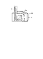
도 5는, 플라즈마 처리실(30)의 단면도이다. 플라즈마 처리실(30)은 가열실(2)과 마찬가지로 원통형으로 형상 설정되며 적어도 내벽(31)이 금속재로 형성되어 있다.5 is a cross-sectional view of the
피처리물(X)을 플라즈마 처리할 경우에는 피처리물(X)은 금속제의 도전성 트레이(Ta)에 놓여 반송된다. 플라즈마 처리실(30) 내부에는 도전성 트레이(Ta)와 도통하는 전극(32)이 구비되어 있다.When the object X is to be subjected to plasma treatment, the object X is placed in a metal conductive tray Ta and conveyed. In the
전극(32)은 도 5에 도시한 바와 같이 플라즈마 처리실(30)의 내부에 고정 배치되고, 플라즈마 처리실(30)에 피처리물(X)이 반입되었을 때 피처리물(X)이 놓인 도전성 트레이(Ta)와 접촉하는 위치에 배치되어 있다.As shown in FIG. 5, the
상기 플라즈마 처리실(30)을 구비한 다실형 열처리 장치에 의하면, 도전성 트레이(Ta)와 전극(32)은, 승강 장치(9)에 의해 피처리물(X)을 상승시켜 플라즈마 처리실(30)에 수용이 완료된 시점에서 도통한다. 즉, 도전성 트레이(Ta)와 전극(32)의 도통을 확보하는 동작을 별도로 행하지 않고 도전성 트레이(Ta)와 전극(32)을 용이하게 도통시킬 수 있다.According to the multi-room heat treatment apparatus provided with the said
예를 들면 내벽(31)을 접지하여 베이스 전위로 하고 전극(32)을 통해 피처리물(X)에 음전압을 인가함으로써 내벽(31)과 피처리물(X) 사이에 플라즈마가 발생하여 피처리물(X)이 플라즈마 처리된다.For example, by grounding the
본 발명의 다실형 열처리 장치에서는 가열실(2)과 더불어, 혹은 가열실(2) 대신에, 플라즈마 처리실(30)을 설치해도 좋다. 플라즈마 처리실(30)을 구비한 경우에는 도전성 트레이(Ta)와 전극(32)을 용이하게 도통시킬 수 있어 피처리물(X)의 플라즈마 처리를 용이하게 행할 수 있게 된다.In the multi-chamber heat treatment apparatus of the present invention, a
본 실시형태의 다실형 열처리 장치(S1)의 설명으로 되돌아간다. 본 실시형태의 다실형 열처리 장치(S1)에서는, 가열실(2)과 냉각실(3) 사이에 중간 반송실(1)을 구비한 구성을 채용하였다.Returning to the description of the polysilicon heat treatment apparatus S1 of this embodiment. In the multi-chamber heat processing apparatus S1 of this embodiment, the structure provided with the intermediate |
상기 구성을 채용하는 본 실시형태의 다실형 열처리 장치(S1)에 의하면, 가령 냉각실(3)에서 냉각액이 유출된 경우라 해도 중간 반송실(1)이 완충 영역이 되어 냉각액이 가열실(2)까지 도달하는 것을 방지할 수 있다. 따라서 본 실시형태의 다실형 열처리 장치(S1)에 의하면, 피처리물(X)에 대한 가열 처리를 안정적으로 행할 수 있게 된다.According to the multi-chamber heat treatment apparatus S1 of this embodiment which employ | adopts the said structure, even if the cooling liquid flows out from the cooling
또 본 실시형태의 다실형 열처리 장치(S1)에 의하면, 접속되는 처리실(중간 반송실(1), 가열실(2) 및 냉각실(3))들이 높이 방향으로 배치되어 접속된 처리실 사이에서 피처리물(X)을 주고받는 것이 승강 장치(9),(23)에 의해 이루어진다.Moreover, according to the multi-chamber heat processing apparatus S1 of this embodiment, the process chambers (
본 실시형태의 다실형 열처리 장치(S1)는 위에서 본 형상이 컴팩트해지므로 작은 설치 면적에 설치할 수 있다. 또 피처리물(X)을 아래쪽에서 지지하면서 수직 반송하는 기회가 증가함에 따라 피처리물(X)을 안정적으로 반송할 수 있다.The polysilicon heat treatment apparatus S1 of this embodiment can be installed in a small installation area because the shape seen from above is compact. Moreover, as the opportunity to vertically convey the to-be-processed object X while supporting it from below, the to-be-processed object X can be conveyed stably.
이상, 도면을 참조하여 본 발명의 바람직한 실시형태에 대해 설명하였으나 본 발명은 상기 실시형태로 한정되지는 않는다. 상술한 실시형태에서 나타낸 각 구성 부재의 모든 형상이나 조합 등은 일례로서, 본 발명의 주지를 벗어나지 않는 범위에서 설계 요구 등에 근거하여 다양하게 변경 가능하다.As mentioned above, although preferred embodiment of this invention was described with reference to drawings, this invention is not limited to the said embodiment. All shapes, combinations, and the like of the respective constituent members shown in the above-described embodiments are examples and can be variously changed based on design requirements and the like without departing from the scope of the present invention.
예를 들면 상기 실시형태에서는, 냉각실(3) 이외의 다른 처리실로서 중간 반송실(1) 및 가열실(2)을 구비한 구성에 대해 설명하였다.For example, in the said embodiment, the structure provided with the intermediate |
그러나 본 발명은 이에 한정되지는 않으며, 예를 들면 처리실로서 냉각실과 가열실만을 구비한 다실형 열처리 장치, 처리실로서 냉각실과 반송실만을 구비한 다실형 열처리 장치, 처리실로서 냉각실과 플라즈마 처리실만을 구비한 다실형 열처리 장치에 적용해도 좋다.However, the present invention is not limited thereto. For example, a multi-room heat treatment apparatus having only a cooling chamber and a heating chamber as a treatment chamber, a multi-room heat treatment apparatus having only a cooling chamber and a conveying chamber as a treatment chamber, and a cooling chamber and a plasma treatment chamber as a treatment chamber are provided. You may apply to a multi-chamber heat processing apparatus.
또 상기 실시형태에서는, 냉각실(3)에서 미스트의 잠열에 의해 피처리물(X)을 냉각시키는 구성에 대해 설명하였다.Moreover, in the said embodiment, the structure which cools to-be-processed object X by the latent heat of mist in the
그러나 본 발명은 이에 한정되지는 않으며, 미스트보다 입경이 큰 액체 입자의 잠열에 의해 피처리물(X)을 냉각시키는 다실형 열처리 장치에 적용해도 좋다.However, this invention is not limited to this, You may apply to the multi-chamber heat processing apparatus which cools the to-be-processed object X by the latent heat of the liquid particle whose particle diameter is larger than a mist.
또 상기 실시형태에서는, 냉각실(3)에 미스트를 충전하는 구성에 대해 설명하였다.Moreover, in the said embodiment, the structure which fills the mist in the
그러나 본 발명은 이에 한정되지는 않으며, 냉각실(3)내의 피처리물(X)에 대해 미스트를 내뿜어 피처리물(X)을 냉각시키는 구성을 채용해도 좋다.However, this invention is not limited to this, You may employ | adopt the structure which cools the to-be-processed object X by blowing mist with respect to the to-be-processed object X in the
또 상기 실시형태에서는, 열풍 공급 장치(19)와 가스 공급 장치(11) 모두를 구비하고 열풍 공급 장치(19)와 가스 공급 장치(11) 중 어느 것으로든 냉각실(3)을 건조시킬 수 있는 구성에 대해 설명하였다.Moreover, in the said embodiment, it is provided with both the hot
그러나 본 발명은 이에 한정되지는 않으며, 예를 들면 열풍 공급 장치(19)만을 구비한 구성을 채용해도 좋다.However, this invention is not limited to this, For example, you may employ | adopt the structure provided only with the hot
또 상기 실시형태에서는, 접속되는 처리실(중간 반송실(1), 가열실(2) 및 냉각실(3))들이 높이 방향으로 배치되어 접속된 처리실 사이에서 피처리물(X)을 주고받는 것이 승강 장치(9),(23)에 의해 이루어지는 구성에 대해 설명하였다.Moreover, in the said embodiment, the process chamber (
그러나 본 발명은 이에 한정되지는 않으며, 접속되는 처리실들을 수평으로 배치하고 접속된 처리실 사이에서 피처리물(X)을 주고받는 것을 수평 반송에 의해 행해도 좋다.However, this invention is not limited to this, You may arrange | position the process chambers connected horizontally and send and receive the to-be-processed object X between connected process chambers by horizontal conveyance.
또 상기 실시형태에서는, 중간 반송실(1)에 대해 피처리물(X)을 출입시키는 구성을 채용했다.Moreover, in the said embodiment, the structure which makes the to-be-processed object X enter and exit with respect to the intermediate |
그러나 본 발명은 이에 한정되지는 않으며, 예를 들면 냉각실(3)에서 피처리물(X)을 출입시키는 구성이나 냉각실(3)에서 피처리물(X)를 꺼내기만 행하는 구성을 채용해도 좋다.However, this invention is not limited to this, For example, even if the structure which carries out the to-be-processed object X from the cooling
<산업상 이용 가능성>Industrial availability
본 발명에 의하면, 건조 장치에 의해 냉각실의 건조가 행해진다. 따라서 냉각실과 다른 처리실 사이에서의 피처리물의 주고받기에 앞서 냉각실을 건조시킴으로써 냉각실 내에 잔존하는 냉각액(액체 입자 및 상기 액체 입자가 응집된 액체를 포함한다)이 증발하여 상기 냉각액이 다른 처리실에 유입되는 것을 방지할 수 있다. 따라서 본 발명에 의하면, 다실형 열처리 장치에서 냉각실 이외의 다른 처리실이 냉각액으로 오염되는 것을 방지할 수 있게 된다.According to this invention, drying of a cooling chamber is performed by a drying apparatus. Therefore, the coolant remaining in the cooling chamber (including liquid particles and agglomerated liquid particles) is evaporated by drying the cooling chamber prior to the exchange of the processing object between the cooling chamber and the other processing chamber, and the cooling liquid is transferred to the other processing chamber. Inflow can be prevented. Therefore, according to the present invention, it is possible to prevent the processing chamber other than the cooling chamber from being contaminated with the cooling liquid in the multi-chamber heat treatment apparatus.
S1……다실형 열처리 장치, 1……중간 반송실(처리실), 1a……중앙실, 1a1~1a8……측벽, 1b……가열용 승강실, 2……가열실(처리실, 열처리실), 3……냉각실(처리실, 열처리실), 4……반출입문, 5……푸쉬 장치, 6……상부덮개, 7……상부덮개 승강 장치, 8……안착대, 9……승강 장치, 10……안착대, 11……가스 공급 장치(건조 장치), 12……중간 반송실용 진공 펌프, 13……히터, 14……가스 공급 장치, 15……가열실용 진공 펌프, 16……노즐, 17……헤더관, 18……냉각액 회수 공급 장치, 18a……냉각액 탱크, 18b……냉각액 펌프, 18c……열교환기, 19……열풍 공급 장치(건조 장치), 20……냉각실용 진공 펌프, 21……냉각 팬, 22……안착대, 23……승강 장치, 30……플라즈마 처리실, 31……내벽, 32……전극, T……트레이, Ta……도전성 트레이, X……피처리물S1... ... Multi-threaded heat treatment apparatus, 1... ... Intermediate conveying chamber (processing chamber), 1a... ... Central room, 1a1-1a8.. ... Sidewall, 1b... ... Heating chamber, 2... ... Heating chamber (process chamber, heat treatment chamber), 3... ... Cooling chamber (process chamber, heat treatment chamber), 4... ... Exit door, 5... ... Push device, 6... ... Top cover, 7.. ... Top cover elevating device, 8... ... Seating area, 9... ... Lifting device, 10... ... Seating table, 11... ... Gas supply unit (drying unit), 12.. ... Vacuum pump for intermediate transfer chamber, 13... ... Heater, 14... ... Gas supply device, 15... ... Vacuum pump for heating chamber, 16... ... Nozzles, 17 ... ... Header tube, 18... ... Coolant recovery supply, 18a... ... Coolant tank, 18b... ... Coolant pump, 18c... ... Heat exchanger, 19... ... Hot air supply unit (drying unit), 20... ... Vacuum pump for cooling chamber, 21... ... Cooling fan, 22... ... Seating area, 23... ... Lifting device, 30... ... Plasma processing chamber, 31... ... Inner wall, 32... ... Electrode, T.. ... Tray, Ta… ... Conductive tray, X... ... Treated matter
Claims (10)
액체 입자의 잠열에 의해 피처리물의 냉각을 행하는 상기 열처리실인 냉각실과,
상기 냉각실과 다른 기타의 처리실과,
상기 냉각실의 건조를 행하는 건조 장치를 구비한 다실형 열처리 장치.A multi-room heat treatment apparatus having a plurality of treatment chambers including a heat treatment chamber,
A cooling chamber which is the heat treatment chamber for cooling the target object by the latent heat of liquid particles;
The cooling chamber and other processing chambers,
The multi-chamber heat processing apparatus provided with the drying apparatus which dries the said cooling chamber.
상기 건조 장치는, 상기 냉각실 내로 열풍을 공급하는 열풍 공급 장치를 구비한 다실형 열처리 장치.The method according to claim 1,
The drying apparatus is a multi-chamber heat treatment apparatus having a hot air supply device for supplying hot air into the cooling chamber.
상기 건조 장치는, 상기 피처리물의 냉각에 사용 가능한 냉각 가스를 상기 냉각실 내로 송풍하여 건조를 행하는 냉각 가스 공급 장치를 구비한 다실형 열처리 장치.The method according to claim 1 or 2,
The drying apparatus is a multi-chamber heat treatment apparatus provided with a cooling gas supply device which blows cooling gas which can be used for cooling the to-be-processed object into the said cooling chamber, and performs drying.
상기 냉각실 내로 상기 액체 입자를 분무하는 노즐과, 상기 노즐에 액체 입자가 되는 냉각액을 안내하는 헤더관을 구비하고,
상기 냉각 가스 공급 장치는, 상기 노즐 및 상기 헤더관을 통해 상기 냉각 가스를 상기 냉각실 내로 송풍하는 다실형 열처리 장치.The method according to claim 3,
A nozzle for spraying the liquid particles into the cooling chamber, and a header tube for guiding the coolant to become liquid particles in the nozzle,
And the cooling gas supply device blows the cooling gas into the cooling chamber through the nozzle and the header tube.
상기 냉각실과 다른 기타의 처리실로서, 상기 피처리물의 가열 처리를 행하는 가열실을 구비한 다실형 열처리 장치.5. The method according to any one of claims 1 to 4,
The multi-chamber heat treatment apparatus provided with the said heat processing room and the other process chambers which heat-process the said to-be-processed object.
상기 냉각실과 다른 기타의 처리실로서, 상기 가열실과 상기 냉각실 사이에 배치되는 중간 반송실을 구비한 다실형 열처리 장치.The method according to claim 5,
A multi-chamber heat treatment apparatus comprising an intermediate transfer chamber disposed between the heating chamber and the cooling chamber as the processing chamber and other processing chambers.
상기 냉각실과 다른 기타의 처리실로서, 상기 피처리물에 대한 플라즈마 처리를 행하는 플라즈마 처리실을 구비한 다실형 열처리 장치.7. The method according to any one of claims 1 to 6,
A multi-chamber heat treatment apparatus comprising: a plasma processing chamber for performing plasma processing on the object to be processed as another processing chamber different from the cooling chamber.
상기 플라즈마 처리실의 내부에 고정 배치됨과 동시에 상기 플라즈마 처리실의 내부에 상기 피처리물이 반입되었을 때에 상기 피처리물이 놓이는 도전성 트레이와 접촉하는 전극을 구비한 다실형 열처리 장치.The method of claim 7,
A multi-chamber heat treatment apparatus having an electrode which is fixedly arranged inside the plasma processing chamber and in contact with a conductive tray on which the workpiece is placed when the workpiece is loaded into the plasma processing chamber.
접속되는 상기 처리실들이 높이 방향으로 배치되고,
접속된 상기 처리실 사이에서 상기 피처리물의 주고받기를 행하는 승강 장치를 구비한 다실형 열처리 장치.The method according to any one of claims 1 to 8,
The processing chambers to be connected are arranged in a height direction,
The multi-chamber heat processing apparatus provided with the elevating apparatus which exchanges the said to-be-processed object between the said process chambers connected.
상기 열풍 공급 장치는, 상기 피처리물이 놓인 상기 냉각실 내로 열풍을 공급함으로써 행하는 뜨임 처리에 사용 가능한 다실형 열처리 장치.The method according to claim 2,
The hot air supply device is a multi-chamber heat treatment device that can be used for a tempering process performed by supplying hot air into the cooling chamber in which the object to be processed is placed.
Applications Claiming Priority (3)
| Application Number | Priority Date | Filing Date | Title |
|---|---|---|---|
| JPJP-P-2010-151563 | 2010-07-02 | ||
| JP2010151563A JP5658928B2 (en) | 2010-07-02 | 2010-07-02 | Multi-chamber heat treatment equipment |
| PCT/JP2011/065179 WO2012002532A1 (en) | 2010-07-02 | 2011-07-01 | Multi-chamber heat treatment device |
Publications (1)
| Publication Number | Publication Date |
|---|---|
| KR20130045343A true KR20130045343A (en) | 2013-05-03 |
Family
ID=45402234
Family Applications (1)
| Application Number | Title | Priority Date | Filing Date |
|---|---|---|---|
| KR1020137002397A KR20130045343A (en) | 2010-07-02 | 2011-07-01 | Multi-chamber heat treatment device |
Country Status (6)
| Country | Link |
|---|---|
| US (1) | US20130153547A1 (en) |
| EP (1) | EP2589910A4 (en) |
| JP (1) | JP5658928B2 (en) |
| KR (1) | KR20130045343A (en) |
| CN (1) | CN103038593B (en) |
| WO (1) | WO2012002532A1 (en) |
Families Citing this family (12)
| Publication number | Priority date | Publication date | Assignee | Title |
|---|---|---|---|---|
| WO2014193388A1 (en) * | 2013-05-30 | 2014-12-04 | Johns Manville | Submerged combustion glass melting systems and methods of use |
| JP6515370B2 (en) * | 2014-05-29 | 2019-05-22 | 株式会社Ihi | Cooling device and multi-chamber heat treatment apparatus |
| JP6418830B2 (en) | 2014-07-25 | 2018-11-07 | 株式会社Ihi | Cooling device and multi-chamber heat treatment device |
| JP6418832B2 (en) * | 2014-07-28 | 2018-11-07 | 株式会社Ihi | Conveying device for heat treatment apparatus and heat treatment apparatus |
| JP6297471B2 (en) * | 2014-11-10 | 2018-03-20 | 中外炉工業株式会社 | Heat treatment equipment |
| DE112015005248B4 (en) | 2014-11-20 | 2019-07-11 | Ihi Corporation | HEAT TREATMENT DEVICE AND COOLING DEVICE |
| JP6596703B2 (en) * | 2015-03-04 | 2019-10-30 | 株式会社Ihi | Multi-chamber heat treatment equipment |
| JP6338314B2 (en) | 2015-05-26 | 2018-06-06 | 株式会社Ihi | Heat treatment equipment |
| JP6721466B2 (en) * | 2016-09-12 | 2020-07-15 | 株式会社Ihi | Heat treatment equipment |
| FR3073937B1 (en) * | 2017-11-21 | 2020-08-14 | Ceritherm | HEAT TREATMENT PLANT FOR THE MANUFACTURE OF INDUSTRIAL PRODUCTS. |
| CN115096076A (en) * | 2021-04-07 | 2022-09-23 | 江苏天海特种装备有限公司 | Tunnel type push rod heating furnace for steam curing and solidifying acetylene cylinder filler and continuous solidifying process |
| CN114197056B (en) * | 2022-01-14 | 2024-07-09 | 浙江大学杭州国际科创中心 | Annealing device and annealing method for semiconductor material |
Family Cites Families (21)
| Publication number | Priority date | Publication date | Assignee | Title |
|---|---|---|---|---|
| US3403451A (en) * | 1965-03-30 | 1968-10-01 | Fluid Energy Proc & Equipment | Method for drying or treating wet solid and semisolid materials |
| US3886760A (en) * | 1970-09-03 | 1975-06-03 | Stephen Wyden | Method of indirect heat exchange |
| NL165222C (en) * | 1972-11-21 | 1981-03-16 | Prolizenz Ag | METHOD AND APPARATUS FOR HEAT TREATMENT OF MATERIAL, SUCH AS BARS, BLOCKS, TUBES AND THE LIKE. |
| DE4005956C1 (en) * | 1990-02-26 | 1991-06-06 | Siegfried Dipl.-Ing. Dr. 5135 Selfkant De Straemke | |
| JP3310997B2 (en) * | 1991-11-28 | 2002-08-05 | 株式会社日立製作所 | Continuous processing equipment |
| CN1052566C (en) * | 1993-11-05 | 2000-05-17 | 株式会社半导体能源研究所 | Method for processing semiconductor device, apparatus for processing a semiconductor and apparatus for processing semiconductor device |
| JP3490791B2 (en) * | 1994-12-20 | 2004-01-26 | 光洋サーモシステム株式会社 | Multi-chamber heat treatment furnace |
| US6059507A (en) * | 1997-04-21 | 2000-05-09 | Brooks Automation, Inc. | Substrate processing apparatus with small batch load lock |
| JPH11153386A (en) | 1997-11-25 | 1999-06-08 | Ishikawajima Harima Heavy Ind Co Ltd | Multichamber multi-cooling vacuum furnace |
| JP3820950B2 (en) * | 2001-10-03 | 2006-09-13 | 大同特殊鋼株式会社 | Atmospheric heat treatment furnace and its seasoning method |
| US8530359B2 (en) * | 2003-10-20 | 2013-09-10 | Novellus Systems, Inc. | Modulated metal removal using localized wet etching |
| US7841582B2 (en) * | 2004-06-02 | 2010-11-30 | Applied Materials, Inc. | Variable seal pressure slit valve doors for semiconductor manufacturing equipment |
| US9799536B2 (en) * | 2005-02-07 | 2017-10-24 | Planar Semiconductor, Inc. | Apparatus and method for cleaning flat objects in a vertical orientation with pulsed liquid jet |
| US7845891B2 (en) * | 2006-01-13 | 2010-12-07 | Applied Materials, Inc. | Decoupled chamber body |
| US8124907B2 (en) * | 2006-08-04 | 2012-02-28 | Applied Materials, Inc. | Load lock chamber with decoupled slit valve door seal compartment |
| US20090001057A1 (en) * | 2007-06-29 | 2009-01-01 | Cheng-Hsin Ma | Dual damascene trench depth detection and control using voltage impedance RF probe |
| US20110155192A1 (en) * | 2008-02-27 | 2011-06-30 | Nadeem Ahmad | System and apparatus for automatic built-in vehicle washing and other operations |
| JP2010014290A (en) * | 2008-07-01 | 2010-01-21 | Ihi Corp | Multiple-chamber type heat treat furnace |
| JP2010038531A (en) * | 2008-07-10 | 2010-02-18 | Ihi Corp | Heat treatment device |
| US20100024847A1 (en) * | 2008-08-01 | 2010-02-04 | Breese Ronald G | Semiconductor wafer cleaning with dilute acids |
| JP5203986B2 (en) * | 2009-01-19 | 2013-06-05 | 東京エレクトロン株式会社 | Focus ring heating method, plasma etching method, plasma etching apparatus and computer storage medium |
-
2010
- 2010-07-02 JP JP2010151563A patent/JP5658928B2/en not_active Expired - Fee Related
-
2011
- 2011-07-01 WO PCT/JP2011/065179 patent/WO2012002532A1/en active Application Filing
- 2011-07-01 CN CN201180031206.5A patent/CN103038593B/en not_active Expired - Fee Related
- 2011-07-01 KR KR1020137002397A patent/KR20130045343A/en active IP Right Grant
- 2011-07-01 US US13/806,159 patent/US20130153547A1/en not_active Abandoned
- 2011-07-01 EP EP11800994.3A patent/EP2589910A4/en not_active Withdrawn
Also Published As
| Publication number | Publication date |
|---|---|
| EP2589910A4 (en) | 2016-08-24 |
| EP2589910A1 (en) | 2013-05-08 |
| CN103038593A (en) | 2013-04-10 |
| JP5658928B2 (en) | 2015-01-28 |
| CN103038593B (en) | 2015-09-16 |
| WO2012002532A1 (en) | 2012-01-05 |
| US20130153547A1 (en) | 2013-06-20 |
| JP2012013341A (en) | 2012-01-19 |
Similar Documents
| Publication | Publication Date | Title |
|---|---|---|
| KR20130045343A (en) | Multi-chamber heat treatment device | |
| JP3194036B2 (en) | Drying treatment apparatus and drying treatment method | |
| US9101995B2 (en) | Apparatus for thermal melting process and method of thermal melting process | |
| WO2010005083A1 (en) | Heat treatment apparatus | |
| KR20060109852A (en) | Load lock apparatus and processing method | |
| JP2009164213A (en) | Vacuum processing apparatus and vacuum processing method, and storage medium | |
| JP6043551B2 (en) | Heat treatment method | |
| US20060112973A1 (en) | Method and apparatus for substrate processing | |
| JP2012013341A5 (en) | ||
| WO2016080197A1 (en) | Heat treatment device and cooling device | |
| US20140263273A1 (en) | Chamber apparatus and heating method | |
| US7935188B2 (en) | Vertical thermal processing apparatus and method of using the same | |
| KR20100105354A (en) | Substrate processing apparatus | |
| WO2014199538A1 (en) | Vacuum treatment device | |
| JP4652500B2 (en) | Method of heat-treating workpiece with at least one heat transfer liquid and condensing furnace for realizing the method | |
| JP5571291B2 (en) | Heat treatment equipment | |
| JP2001148379A (en) | Device and method for heat treatment of semiconductor substrate | |
| KR20090106991A (en) | Substrate treatment apparatus, substrate treatment method and recording medium having program recorded | |
| JP6341625B2 (en) | Heat treatment equipment | |
| KR101898340B1 (en) | Substrate cooling method, substrate transfer method, and load-lock mechanism | |
| JP6296657B2 (en) | Heat treatment equipment | |
| JP5634127B2 (en) | Heat treatment furnace | |
| KR20080020527A (en) | Vacuum processing apparatus and vacuum processing method | |
| JP2015190029A (en) | Vacuum evaporation device, and crucible carry-in/out mechanism and crucible carry-in/out method | |
| JP5184477B2 (en) | Drying chamber, cleaning / drying processing apparatus, drying processing method, and recording medium |
Legal Events
| Date | Code | Title | Description |
|---|---|---|---|
| A201 | Request for examination | ||
| E902 | Notification of reason for refusal | ||
| E701 | Decision to grant or registration of patent right | ||
| NORF | Unpaid initial registration fee |