JP2012000702A - Cutting apparatus - Google Patents
Cutting apparatus Download PDFInfo
- Publication number
- JP2012000702A JP2012000702A JP2010136478A JP2010136478A JP2012000702A JP 2012000702 A JP2012000702 A JP 2012000702A JP 2010136478 A JP2010136478 A JP 2010136478A JP 2010136478 A JP2010136478 A JP 2010136478A JP 2012000702 A JP2012000702 A JP 2012000702A
- Authority
- JP
- Japan
- Prior art keywords
- cutting
- rotation
- rotating
- nozzle
- cutting blade
- Prior art date
- Legal status (The legal status is an assumption and is not a legal conclusion. Google has not performed a legal analysis and makes no representation as to the accuracy of the status listed.)
- Granted
Links
- 238000005520 cutting process Methods 0.000 title claims abstract description 98
- 239000002173 cutting fluid Substances 0.000 claims abstract description 44
- 230000002093 peripheral effect Effects 0.000 claims abstract description 19
- 238000002347 injection Methods 0.000 description 12
- 239000007924 injection Substances 0.000 description 12
- 239000004065 semiconductor Substances 0.000 description 10
- 235000012431 wafers Nutrition 0.000 description 10
- 230000000149 penetrating effect Effects 0.000 description 7
- 230000003028 elevating effect Effects 0.000 description 6
- 230000035515 penetration Effects 0.000 description 5
- XUIMIQQOPSSXEZ-UHFFFAOYSA-N Silicon Chemical compound [Si] XUIMIQQOPSSXEZ-UHFFFAOYSA-N 0.000 description 2
- 230000008878 coupling Effects 0.000 description 2
- 238000010168 coupling process Methods 0.000 description 2
- 238000005859 coupling reaction Methods 0.000 description 2
- 229910052710 silicon Inorganic materials 0.000 description 2
- 239000010703 silicon Substances 0.000 description 2
- 239000002699 waste material Substances 0.000 description 2
- GYHNNYVSQQEPJS-UHFFFAOYSA-N Gallium Chemical compound [Ga] GYHNNYVSQQEPJS-UHFFFAOYSA-N 0.000 description 1
- 229910001218 Gallium arsenide Inorganic materials 0.000 description 1
- 230000009471 action Effects 0.000 description 1
- 239000000853 adhesive Substances 0.000 description 1
- 230000001070 adhesive effect Effects 0.000 description 1
- 239000000919 ceramic Substances 0.000 description 1
- 230000008859 change Effects 0.000 description 1
- 238000001816 cooling Methods 0.000 description 1
- 238000009826 distribution Methods 0.000 description 1
- 230000009977 dual effect Effects 0.000 description 1
- 239000012530 fluid Substances 0.000 description 1
- 229910052733 gallium Inorganic materials 0.000 description 1
- 239000011521 glass Substances 0.000 description 1
- 230000006872 improvement Effects 0.000 description 1
- 239000004973 liquid crystal related substance Substances 0.000 description 1
- 238000004519 manufacturing process Methods 0.000 description 1
- 239000000463 material Substances 0.000 description 1
- 238000000034 method Methods 0.000 description 1
- TWNQGVIAIRXVLR-UHFFFAOYSA-N oxo(oxoalumanyloxy)alumane Chemical compound O=[Al]O[Al]=O TWNQGVIAIRXVLR-UHFFFAOYSA-N 0.000 description 1
- HBMJWWWQQXIZIP-UHFFFAOYSA-N silicon carbide Chemical compound [Si+]#[C-] HBMJWWWQQXIZIP-UHFFFAOYSA-N 0.000 description 1
- 239000007921 spray Substances 0.000 description 1
- 238000005507 spraying Methods 0.000 description 1
- XLYOFNOQVPJJNP-UHFFFAOYSA-N water Substances O XLYOFNOQVPJJNP-UHFFFAOYSA-N 0.000 description 1
Images


Landscapes
- Dicing (AREA)
Abstract
Description
本発明は、半導体ウェーハ等のワークを切削する切削加工装置に関する。 The present invention relates to a cutting apparatus for cutting a workpiece such as a semiconductor wafer.
例えば、半導体デバイス製造工程においては、略円板形状である半導体ウェーハの表面に格子状に配列された多数の領域にIC、LSI等の回路を形成し、各領域を所定のストリート(切断ライン)に沿って切断することにより個々の半導体チップを製造している。このように半導体ウェーハを切断する精密切削加工装置、例えばダイシング装置においては、高速回転するスピンドルの先端部に装着された切削ブレードを用いて、半導体ウェーハ等の被加工物を切削する。このようなダイシング装置では、切削ブレードの外周を覆うようにブレードカバーが配設されている。このブレードカバーには、切削ブレードや加工点を冷却したり、切削屑を押し流したりするために、切削ブレードの両側面(Y軸方向前面および背面)側から切削液を供給する一対の側面ノズル(ブレードクーラノズル)が設けられている。そして、切削ブレードの外周面に対して半径方向外側から切削液を供給する外周ノズル(シャワーノズル)が設置されたものが知られている(例えば、特許文献1参照)。この外周ノズルは、通常、切削ブレードの外周面と対向するように切削方向前方に配設されている。 For example, in a semiconductor device manufacturing process, circuits such as ICs and LSIs are formed in a large number of regions arranged in a grid on the surface of a substantially disc-shaped semiconductor wafer, and each region is defined as a predetermined street (cutting line). The individual semiconductor chips are manufactured by cutting along. Thus, in a precision cutting apparatus that cuts a semiconductor wafer, for example, a dicing apparatus, a workpiece such as a semiconductor wafer is cut using a cutting blade mounted on the tip of a spindle that rotates at high speed. In such a dicing apparatus, a blade cover is disposed so as to cover the outer periphery of the cutting blade. The blade cover is provided with a pair of side nozzles that supply cutting fluid from both side surfaces (front and back surfaces in the Y-axis direction) of the cutting blade in order to cool the cutting blade and the processing point and to flush away the cutting waste. A blade cooler nozzle) is provided. And what was provided with the outer periphery nozzle (shower nozzle) which supplies a cutting fluid from the radial direction outer side with respect to the outer peripheral surface of a cutting blade is known (for example, refer patent document 1). This outer peripheral nozzle is normally disposed in front of the cutting direction so as to face the outer peripheral surface of the cutting blade.
しかしながら、上記の外周ノズルを設置する場合、切削ブレードに対して最も適した状態で切削水を供給するために、外周ノズルを様々な角度となるように調整する必要があるが、外周ノズルの精密な角度合わせを行うことは作業が煩雑であり改善が求められていた。 However, when the above-mentioned outer peripheral nozzle is installed, it is necessary to adjust the outer peripheral nozzle to have various angles in order to supply cutting water in a state most suitable for the cutting blade. Performing proper angle adjustment is complicated and requires improvement.
この発明は、上記に鑑みてなされたものであって、切削ブレードの半径方向外側から切削ブレードの周縁に向けて切削液を供給するノズルの角度調整を容易にできる切削加工装置を提供することを目的とする。 The present invention has been made in view of the above, and provides a cutting device that can easily adjust the angle of a nozzle that supplies a cutting fluid from the radially outer side of a cutting blade toward the periphery of the cutting blade. Objective.
上述した課題を解決し、目的を達成するために、本発明にかかる切削加工装置は、ワークを保持する保持手段と、該保持手段に保持されたワークを、Y方向を回転軸として回転する円盤状の切削ブレードで加工する切削加工手段と、該切削ブレードに切削液を供給する切削液供給手段と、を含む切削装置であって、該切削液供給手段は、該切削ブレードの半径方向外周側から該切削ブレードへ向けて該切削液を噴射する噴出部、および該噴出部が形成された回転部を有するノズルと、該ノズルの該回転部をY方向を回転軸として回転可能に支持するノズル支持部と、該回転部の回転角度を調整する角度調整部と、を有し、該角度調整部は、該回転部の外周に形成された、該回転部の回転に対する半径方向外側へ高さを有し、該回転部の回転軸に対して螺旋を描くように形成された板部と、該板部上に、該回転部の回転軸に対して円弧状に形成された貫通穴と、該板部材の該貫通穴に貫通する貫通部、および該貫通部の両端に形成され該貫通部が該貫通穴に貫通した状態で該板部を両側から挟むフランジ、およびY方向を回転軸とする雄ネジ部が形成されたシャフトと、該雄ネジ部に螺合する雌ネジ部が該貫通穴へ対応する位置に形成されたシャフト支持部と、を有し、該シャフト支持部の該雌ネジ部に螺合された該雄ネジ部を回転させ、該フランジ部を該Y方向に進退移動させることによって該フランジと該板部が摺動し、該回転部がY方向を回転軸として回動することを特徴とする。 In order to solve the above-described problems and achieve the object, a cutting apparatus according to the present invention includes a holding unit that holds a workpiece, and a disk that rotates the workpiece held by the holding unit about the Y direction as a rotation axis. A cutting device comprising: a cutting means for processing with a shaped cutting blade; and a cutting fluid supply means for supplying a cutting fluid to the cutting blade, wherein the cutting fluid supply means is a radially outer peripheral side of the cutting blade. A nozzle having a jet part for jetting the cutting fluid from the nozzle toward the cutting blade, a rotating part in which the jet part is formed, and a nozzle for rotatably supporting the rotary part with the Y direction as a rotation axis A support portion and an angle adjustment portion for adjusting a rotation angle of the rotation portion, and the angle adjustment portion is formed on an outer periphery of the rotation portion, and has a height outward in the radial direction with respect to the rotation of the rotation portion. A rotating shaft of the rotating part A plate portion formed so as to draw a spiral, a through hole formed on the plate portion in an arc shape with respect to the rotation axis of the rotating portion, and a through hole penetrating the through hole of the plate member And a shaft formed on both ends of the penetrating portion, the flange sandwiching the plate portion from both sides in a state in which the penetrating portion penetrates the through hole, and a shaft formed with a male screw portion having a rotation axis in the Y direction, A male screw part screwed into the female screw part of the shaft support part, and a female screw part screwed into the male screw part, and a shaft support part formed at a position corresponding to the through hole. , And the flange portion is moved forward and backward in the Y direction, whereby the flange and the plate portion slide, and the rotating portion rotates about the Y direction as a rotation axis.
この発明によれば、切削ブレードの半径方向外側から切削ブレードの周縁に向けて切削液を供給するノズルの角度調整を容易にできる切削加工装置を実現することができる。 According to the present invention, it is possible to realize a cutting apparatus that can easily adjust the angle of a nozzle that supplies a cutting fluid from the radially outer side of the cutting blade toward the periphery of the cutting blade.
以下に、本発明を実施するための形態である切削加工装置について図面を参照して説明する。但し、図面は模式的なものを含み、図面相互間において互いの寸法の関係や比率が異なる部分が含まれている。 Below, the cutting device which is a form for carrying out the present invention is explained with reference to drawings. However, the drawings include schematic ones, and include portions having different dimensional relationships and ratios between the drawings.
図1に示すように、本実施の形態にかかる切削加工装置1は、シリコンウェーハでなるワーク2を保持する保持手段としてのチャックテーブル3と、チャックテーブル3に保持されたワーク2を切削加工する第1の切削加工手段4および第2の切削加工手段5とを備える。
As shown in FIG. 1, a cutting apparatus 1 according to the present embodiment cuts a chuck table 3 as a holding unit that holds a
図1に示すように、チャックテーブル3は、ワーク2の位置固定が可能であり、載置面上にワーク2を吸着して保持する図示しない吸着手段が設けられている。チャックテーブル3側は、装置基盤1A上にX方向に沿って形成された一対のガイドレール1B,1Cに案内されるようになっており、装置基盤1A上に設けられたパルスモータ14で同軸的に回転するボールネジ15に螺合してX方向へ進退移動できるようになっている。
As shown in FIG. 1, the chuck table 3 can fix the position of the
本実施の形態にかかる切削加工装置1は、チャックテーブル3の上方をY方向に横切る門型形状に形成され、かつ装置基盤1Aに立設された固定ベース16を備える。この固定ベース16には、第1の切削加工手段4が設けられた第1の昇降プレート17を支持する第1の支持ベース18と、第2の切削加工手段5が設けられた第2の昇降プレート19を支持する第2の支持ベース20とが設けられている。これら第1の支持ベース18側と第2の支持ベース20は、固定ベース16にY方向(幅方向)に沿って形成された一対の平行なガイドレール21A,21BによりY方向に案内されるようになっている。
The cutting apparatus 1 according to the present embodiment includes a
図1に示すように、第1の支持ベース18には、Z方向(上下方向)に沿って一対のガイドレール22A,22Bが形成され、第2の支持ベース20にも、Z方向(上下方向)に沿って一対のガイドレール23A,23Bが形成されている。第1の支持ベース18に形成された一対のガイドレール22A,22Bには、第1の昇降プレート17がZ方向に案内されるようになっている。第2の支持ベース20に形成された一対のガイドレール23A,23Bには、第2の昇降プレート19がZ方向に案内されるようになっている。これら第1の昇降プレート17および第2の昇降プレート19は、パルスモータ24,25、ボールネジ26,27によりZ方向に駆動されるようになっている。
As shown in FIG. 1, a pair of guide rails 22 </ b> A and 22 </ b> B is formed in the
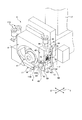
図2に示すように、第1の切削加工手段4は、円盤状の第1の切削ブレード6と、この第1の切削ブレード6に同軸的に回転するように設けられ、この第1の切削ブレード6を回転駆動する第1のスピンドル7と、第1の切削ブレード6を覆う第1のブレードカバー8とを備える。図1に示すように、第2の切削加工手段5は、図示しない円盤状の第2の切削ブレードと、この第2の切削ブレードを回転駆動する第2のスピンドル9と、第2の切削ブレードを覆う第2のブレードカバー10と、を備える。
As shown in FIG. 2, the first cutting means 4 is provided with a disk-shaped
図2に示すように、第1のブレードカバー8には、第1のブレード6の両面側に切削液を供給する一対の第1の側面ノズル11と、第1のブレード6の外周面に切削液を供給する第1の外周切削液供給手段12が設けられている。図1に示すように、第2のブレードカバー10においても同様に、図示なし一対の第2の側面ノズルと、図示しない第2のブレードの外周面に切削液を供給する第2の外周切削液供給手段13が設けられている。
As shown in FIG. 2, the
第1のスピンドル7および第2のスピンドル9の軸心、すなわち切削ブレードの回転軸は、割り出し送り方向となるY方向(第1の切削ブレード6と第2の切削ブレードとが互いに接近離反する方向)と平行をなすように設定されている。ここで、第1の切削ブレード6と図示しない第2の切削ブレードはY方向において互いに向き合うように配置され、フェイシングダイサとして構成されている。また、これら第1の切削ブレード6と図示しない第2の切削ブレードは、デュアルカット用に同種であってもよいし、また、ステップカット用に異種であってもよい。
The axis of the
上述のように、第1の切削加工手段4と第2の切削加工手段5は、互いに対向して配置されて向きが逆であることを除いて、略同様の構成であるため、以下、第1の切削加工手段4における第1の側面ノズル11および第1の外周切削液供給手段12について説明し、第2の切削加工手段5における第2の側面ノズルや第2の外周切削液供給手段13の構成の説明は省略する。
As described above, the first cutting means 4 and the second cutting means 5 have substantially the same configuration except that they are arranged opposite to each other and have opposite directions. The
図2に示すように、一対の第1の側面ノズル11は、第1のブレードカバー8のX方向の一方側の端部に取り付けられ、第1の切削ブレード6を挟むように両側に配置されている。この第1の側面ノズル11は、図示しない切削液供給配管に接続される、第1のブレードカバー8の端部に固定された固定部11Aと、第1の切削ブレード6の下端部側方位置まで延在されたノズル形成パイプ11Bとでなる。なお、図2に示すように、ノズル形成パイプ11Bの先端部における第1の切削ブレード6に対向する部分に図示しないノズルが開口されている。図2に示す矢印wは、ノズル形成パイプ11Bの先端部から噴出された切削液を示す。
As shown in FIG. 2, the pair of
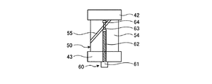
図2および図3に示すように、第1の外周切削液供給手段12は、本体ブロック40と、ノズルとしての回転調整ノズル体50と、シャフトしての調整用ネジ60と、を備えている。
As shown in FIGS. 2 and 3, the first peripheral cutting fluid supply means 12 includes a
図2および図3に示すように、本体ブロック40は、所定間隔を隔てて互いに平行をなす、ノズル支持部としてのノズル支持板部42とこのノズル支持板部42より短いシャフト支持部としての調整用ネジ支持板部43が、直方体形状のブロック部41の下端部に一体に延在するように形成されている。すなわち、ブロック部41の下方に延びるノズル支持板部42と調整用ネジ支持板部43とでは、調整用ネジ支持板部43の方が短くなっている。調整用ネジ支持板部43と調整用ネジ60とは、角度調整部を構成している。
As shown in FIGS. 2 and 3, the
ブロック部41には、上下方向に長い一対の長穴44がY方向に所定間隔を隔てて形成されている。なお、これら長穴44は、ブロック部41をX方向に貫通して形成されている。また、ノズル支持板部42の下部には、調整用ネジ支持板部43側へ向けて(Y方向に沿って)ノズル体回転支持軸48が突設されている。なお、このノズル体回転支持軸48は、後述する回転調整ノズル体50の回転軸を通る回転支持軸嵌合口52に嵌合されている。このとき、調整用ネジ支持板部43は、回転調整ノズル体50の回転に干渉しないように設定されている。
A pair of
図3に示すように、ブロック部41、ノズル支持板部42、およびノズル体回転支持軸48には、切削液が内部を通る二点鎖線で示す切削液流通路47が形成されている。ブロック部41の上端における切削液流通路47の上端部には、連結用継ぎ手45が接続用ナット46を用いて取り付けられている。この連結用継ぎ手45には、図示しない配管が接続されてノズル体回転支持軸48側へ切削液が供給されるようになっている。なお、ノズル体回転支持軸48から回転調整ノズル体50への切削液の供給は、周知のスイベルジョイント構造などを用いてなされるようになっている。
As shown in FIG. 3, a cutting
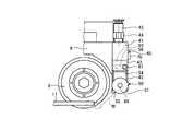
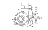
回転調整ノズル体50は、略円柱形状をなし、回転軸を通る中心は回転支持軸嵌合口52が貫通して形成されている回転部51と、この回転部51の周面に回転軸と平行をなすように形成された、切削液を噴射する噴射部53と、回転部51の周面に取付基部54を介して設けられた板部としてのカム板55を備えている。上述のように、回転調整ノズル体50は、ノズル支持板部42に突設されたノズル体回転支持軸48が回転支持軸嵌合口52に嵌合されるように装着され、回転可能となっている。このとき、ノズル体回転支持軸48から回転調整ノズル体50への切削液の供給は、周知のスイベルジョイント構造により供給され、ノズル体回転支持軸48内に形成されている切削液流通路47は、回転部51内の図示しない流路を介して噴射部53へ導かれるようになっている。図5および図6に示すように、噴射部53は、第1の切削ブレード6の半径方向外周側からこの切削ブレード6へ向けて切削液wを噴射するようになっている。
The rotation adjusting
図3に示すように、カム板55は、回転部51の外周に形成され、回転部51の回転に対する半径方向外側へ高さを有し、回転部51の回転軸に対して螺旋を描くように形成されている。図5および図6に示すように、このカム板55には、回転部51に対して回転軸方向から見ると円弧状に形成された貫通穴としてのカム穴56が形成されている。
As shown in FIG. 3, the
調整用ネジ60は、本体ブロック40の調整用ネジ支持板部43に形成された雌ネジ部49に螺合されている。調整用ネジ60は、雌ネジ部49に螺合された状態で、回転調整ノズル体50のカム穴56に対応するように設定されている。図3に示すように、調整用ネジ60は、六角レンチにより調整する調整用凹部61Aが形成された頭部61と、雌ネジ部49に螺合する雄ネジ部62と、雄ネジ部62よりも細く形成されてカム穴56に挿入される貫通部63と、貫通部63の端部に形成され雄ネジ部62と同等の径寸法のフランジ部64と、を備えて形成されている。
The
このように、調整用ネジ60においては、カム穴56に挿入される貫通部63を貫通部63より径の大きい雄ネジ部62とフランジ部64とで挟むことにより、調整用ネジ60がカム板55から外れないような構造となっている。
As described above, in the
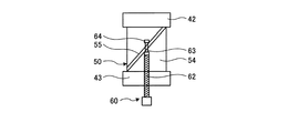
図4−1〜図4−3に示すように、この実施の形態では、調整用ネジ支持板部43の雌ネジ部49に螺合された調整用ネジ60の頭部61の調整用凹部61Aに六角レンチを当てて回動させることにより、雄ネジ部62が回転することに伴い、貫通部63が軸方向に進退移動し、貫通部63とカム板55が摺動する。調整用ネジ支持板部43から貫通部63までの距離により、カム板55との位置関係が一義的に決まるため、カム板55と貫通部63とが滑ることにより、回転部51が軸方向(Y方向)を回転軸として回動する。このような作用により、回転部51に設けられている噴射部53の第1の切削ブレード6に対する角度を変更することができる。
As shown in FIGS. 4A to 4C, in this embodiment, the
上記構成の第1の外周切削液供給手段12は、第1のブレードカバー8における第1の側面ノズル11の固定部11Aが設けられた端部と第1の切削ブレード6を挟む反対側の端部に、一対のネジ70で本体ブロック40が固定されている。この一対のネジ70の長穴44内の位置を調整することで、本体ブロック40の高さ位置を調整することができる。
The first peripheral cutting fluid supply means 12 having the above-described configuration is configured such that the end of the
図4−1に示す状態は、調整用ネジ支持板部43から貫通部63までの距離が一番長い状態であり、このときは回転部51の噴射部53は比較的下向きになるように設定されている。なお、図5に示す状態は、図4−1の状態に加えて、図3に示す長穴44の下端部にネジ70が位置するように本体ブロック40が高い位置にある状態に調整されている。この場合、図5に示すように、噴射部53から噴射される切削液wは第1の切削ブレード6の前側(回転部51に対向する側)に向けて噴射されるようになっている。
The state shown in FIG. 4A is the state in which the distance from the adjustment screw
図4−2に示す状態は、調整用ネジ支持板部43から貫通部63までの距離が長い距離と短い距離の中間の状態であり、回転部51の噴射部53は図4−1の状態よりも上向きに調整されている。なお、図6に示す状態は、図4−2の状態に加えて、図3に示す長穴44の上端部にネジ70が位置するように本体ブロック40が低い位置にある状態に調整されている。この場合、図6に示すように、噴射部53から噴射される切削液wは第1の切削ブレード6の下方に向けて噴射されるようになっている。
The state shown in FIG. 4-2 is a state in which the distance from the adjustment screw
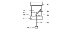
図4−3に示す状態は、調整用ネジ支持板部43から貫通部63までの距離が最も短い距離の状態であり、回転部51の噴射部53は図4−3の状態よりも上向きに調整されている。
The state shown in FIG. 4-3 is a state in which the distance from the adjustment screw
このように、調整用ネジ60を回動操作することにより、噴射する噴射部53の噴射方向を調整できるとともに、長穴44と長穴44におけるネジ70との位置関係の調整により噴射部53の上下位置の調整も可能となる。このため、本実施の形態の切削加工装置1では、切削ブレードや加工点を冷却したり、切削屑を押し流したりする等の目的に応じて切削液の噴射方向を変更したり、切削ブレードの大きさの変更に応じて噴射方向を変更する等の調整を調整用ネジ60で容易に行うことができる。
In this way, by rotating the
以上、切削加工装置1における第1の切削加工手段4について説明したが、第2の切削加工手段5おいても同様の構成である。したがって、この実施の形態に係る切削加工装置1では、第1および第2の切削ブレードの半径方向外側から切削ブレードの周縁に向けて切削液wを供給する噴射部53の角度調整を、調整用ネジ60を回転操作するだけで容易に行うことができる。
The first cutting means 4 in the cutting apparatus 1 has been described above, but the second cutting means 5 has the same configuration. Therefore, in the cutting apparatus 1 according to this embodiment, the angle adjustment of the
(その他の実施の形態)
以上、この発明の実施の形態について説明したが、上記の実施の形態の開示の一部をなす論述および図面はこの発明を限定するものではない。この開示から当業者に様々な代替実施の形態、実施例および運用技術が明らかとなろう。
(Other embodiments)
The embodiment of the present invention has been described above. However, the description and the drawings, which constitute a part of the disclosure of the above embodiment, do not limit the present invention. From this disclosure, various alternative embodiments, examples and operational techniques will be apparent to those skilled in the art.
例えば、上記実施の形態では、ワークとしてシリコンウェーハを用いたが、この他に、ガリウムヒソ(GaAs)、シリコンカーバイド(SiC)等の半導体ウェーハを適用することができる。また、ワークとしては、半導体ウェーハ以外に、チップ実装用としてウェーハの裏面に設けられるDAF(Die Attach Film)等の粘着部材、あるいは半導体製品のパッケージ、セラミック、ガラス、サファイア(Al2O3)、系の無機材料基板、液晶ディスプレイドライバー等の各種電子部品、さらには、ミクロンオーダーの加工位置精度が要求される各種加工材料が挙げられる。 For example, in the above-described embodiment, a silicon wafer is used as a workpiece, but other semiconductor wafers such as gallium hirsode (GaAs) and silicon carbide (SiC) can be applied. In addition to the semiconductor wafer, the workpiece may be an adhesive member such as DAF (Die Attach Film) provided on the back surface of the wafer for chip mounting, or a semiconductor product package, ceramic, glass, sapphire (Al 2 O 3 ), Examples include various inorganic components, various electronic components such as liquid crystal display drivers, and various processing materials that require micron-order processing position accuracy.
また、上記実施の形態では、本体ブロック40と回転調整ノズル体50との切削液の流通をスイベルジョイント構造としたが、この他に、ロータリージョイント構造としてもよいし、回転調整ノズル体50の回転角度範囲は比較的小さいため、可撓性を有する配管を用いて切削液を供給する構成としても勿論よい。
Moreover, in the said embodiment, although distribution | circulation of the cutting fluid of the
さらに、上記実施の形態では、板部としてカム板55を用い貫通穴としてカム穴56を形成したが、貫通穴に代えて、カム板55に、シャフトとしての調整用ネジ60の先端のフランジ部64が抜けないように収容される凹溝形状のカム溝を形成し、調整用ネジ60を回動操作することにより、相対的に凹溝内をフランジ部64がこのカム溝の長手方向に沿って摺動することにより、回転調整ノズル体50の角度調整ができるような構成としてもよい。
Further, in the above embodiment, the
以上のように、本発明にかかる切削加工装置は、半導体ウェーハの切削加工に有用であり、特に、精密切削加工装置、例えばダイシング装置等に適している。 As described above, the cutting apparatus according to the present invention is useful for cutting a semiconductor wafer, and is particularly suitable for a precision cutting apparatus such as a dicing apparatus.
1 切削加工装置
2 ワーク
3 チャックテーブル(保持手段)
4 第1の切削加工手段
5 第2の切削加工手段
6 第1の切削ブレード
8 第1のブレードカバー
12 第1の外周切削液供給手段
13 第2の外周切削液供給手段
40 本体ブロック
42 ノズル支持板部(ノズル支持部)
43 調整用ネジ支持板部(シャフト支持部)
48 ノズル体回転支持軸
49 雌ネジ部
50 回転調整ノズル体(ノズル)
51 回転部
53 噴射部
55 カム板(板部)
56 カム穴(貫通部)
60 調整用ネジ(シャフト)
62 雄ネジ部
63 貫通部
64 フランジ部
1 Cutting
4 1st cutting means 5 2nd cutting means 6
43 Screw support plate for adjustment (shaft support)
48 Nozzle body
51
56 Cam hole (penetrating part)
60 Adjustment screw (shaft)
62
Claims (1)
該切削液供給手段は、
該切削ブレードの半径方向外周側から該切削ブレードへ向けて該切削液を噴射する噴出部、および該噴出部が形成された回転部を有するノズルと、
該ノズルの該回転部をY方向を回転軸として回転可能に支持するノズル支持部と、
該回転部の回転角度を調整する角度調整部と、を有し、
該角度調整部は、
該回転部の外周に形成された、該回転部の回転に対する半径方向外側へ高さを有し、該回転部の回転軸に対して螺旋を描くように形成された板部と、
該板部上に、該回転部の回転軸に対して円弧状に形成された貫通穴と、
該板部材の該貫通穴に貫通する貫通部、および該貫通部の両端に形成され該貫通部が該貫通穴に貫通した状態で該板部を両側から挟むフランジ、およびY方向を回転軸とする雄ネジ部が形成されたシャフトと、
該雄ネジ部に螺合する雌ネジ部が該貫通穴へ対応する位置に形成されたシャフト支持部と、
を有し、
該シャフト支持部の該雌ネジ部に螺合された該雄ネジ部を回転させ、該フランジ部を該Y方向に進退移動させることによって該フランジと該板部が摺動し、該回転部がY方向を回転軸として回動する切削加工装置。 A holding means for holding the work, a cutting means for working the work held by the holding means with a disk-shaped cutting blade rotating around the Y direction as a rotation axis, and a cutting fluid for supplying a cutting fluid to the cutting blade A cutting device including a supply means,
The cutting fluid supply means includes
A nozzle having a jet part for jetting the cutting fluid from the radially outer peripheral side of the cutting blade toward the cutting blade, and a rotating part in which the jet part is formed;
A nozzle support portion for rotatably supporting the rotating portion of the nozzle about the Y direction as a rotation axis;
An angle adjustment unit for adjusting the rotation angle of the rotation unit,
The angle adjustment unit is
A plate portion formed on the outer periphery of the rotating portion, having a height radially outward with respect to the rotation of the rotating portion, and formed in a spiral with respect to the rotation axis of the rotating portion;
On the plate portion, a through hole formed in an arc shape with respect to the rotation axis of the rotating portion;
A through portion that penetrates the through hole of the plate member, a flange that is formed at both ends of the through portion and sandwiches the plate portion from both sides in a state in which the through portion penetrates the through hole, and a rotation direction in the Y direction A shaft formed with a male thread part to be
A shaft support portion in which a female screw portion screwed into the male screw portion is formed at a position corresponding to the through hole;
Have
By rotating the male screw portion screwed into the female screw portion of the shaft support portion and moving the flange portion forward and backward in the Y direction, the flange and the plate portion slide, and the rotating portion is Cutting device that rotates around Y direction.
Priority Applications (1)
| Application Number | Priority Date | Filing Date | Title |
|---|---|---|---|
| JP2010136478A JP5496787B2 (en) | 2010-06-15 | 2010-06-15 | Cutting device |
Applications Claiming Priority (1)
| Application Number | Priority Date | Filing Date | Title |
|---|---|---|---|
| JP2010136478A JP5496787B2 (en) | 2010-06-15 | 2010-06-15 | Cutting device |
Publications (2)
| Publication Number | Publication Date |
|---|---|
| JP2012000702A true JP2012000702A (en) | 2012-01-05 |
| JP5496787B2 JP5496787B2 (en) | 2014-05-21 |
Family
ID=45533299
Family Applications (1)
| Application Number | Title | Priority Date | Filing Date |
|---|---|---|---|
| JP2010136478A Active JP5496787B2 (en) | 2010-06-15 | 2010-06-15 | Cutting device |
Country Status (1)
| Country | Link |
|---|---|
| JP (1) | JP5496787B2 (en) |
Cited By (8)
| Publication number | Priority date | Publication date | Assignee | Title |
|---|---|---|---|---|
| CN102886833A (en) * | 2012-09-21 | 2013-01-23 | 中国电子科技集团公司第四十八研究所 | Cooling liquid spraying device used for sapphire slicing |
| JP2017144510A (en) * | 2016-02-17 | 2017-08-24 | 株式会社ディスコ | Nozzle adjusting tool |
| CN110223937A (en) * | 2018-03-02 | 2019-09-10 | 株式会社迪思科 | Cutter hood |
| CN110435017A (en) * | 2019-08-14 | 2019-11-12 | 郑州光力瑞弘电子科技有限公司 | A kind of main cooling spray of cutter and cutter cooling device, scribing machine |
| CN110435023A (en) * | 2019-08-14 | 2019-11-12 | 郑州光力瑞弘电子科技有限公司 | The main cooling spray of cutter and cutter cooling device, scribing machine |
| CN110653202A (en) * | 2018-06-28 | 2020-01-07 | 株式会社迪思科 | Ultrasonic water jet device |
| CN110893574A (en) * | 2018-09-12 | 2020-03-20 | 株式会社迪思科 | Edge trimming device |
| JP2021000706A (en) * | 2019-06-24 | 2021-01-07 | シチズン時計株式会社 | Coolant supply device and machine tool |
Citations (6)
| Publication number | Priority date | Publication date | Assignee | Title |
|---|---|---|---|---|
| JPS60255349A (en) * | 1984-05-31 | 1985-12-17 | Enshu Ltd | Remote operation apparatus for coolant nozzle |
| JPS642550U (en) * | 1987-06-22 | 1989-01-09 | ||
| JPH0727203A (en) * | 1993-07-09 | 1995-01-27 | Toyota Motor Corp | Phase variable cam device |
| JP2003175484A (en) * | 2001-12-13 | 2003-06-24 | Japan Science & Technology Corp | Man type robot arm |
| JP2006187849A (en) * | 2005-01-07 | 2006-07-20 | Disco Abrasive Syst Ltd | Blade cover device |
| JP2007214201A (en) * | 2006-02-07 | 2007-08-23 | Disco Abrasive Syst Ltd | Cutting apparatus |
-
2010
- 2010-06-15 JP JP2010136478A patent/JP5496787B2/en active Active
Patent Citations (6)
| Publication number | Priority date | Publication date | Assignee | Title |
|---|---|---|---|---|
| JPS60255349A (en) * | 1984-05-31 | 1985-12-17 | Enshu Ltd | Remote operation apparatus for coolant nozzle |
| JPS642550U (en) * | 1987-06-22 | 1989-01-09 | ||
| JPH0727203A (en) * | 1993-07-09 | 1995-01-27 | Toyota Motor Corp | Phase variable cam device |
| JP2003175484A (en) * | 2001-12-13 | 2003-06-24 | Japan Science & Technology Corp | Man type robot arm |
| JP2006187849A (en) * | 2005-01-07 | 2006-07-20 | Disco Abrasive Syst Ltd | Blade cover device |
| JP2007214201A (en) * | 2006-02-07 | 2007-08-23 | Disco Abrasive Syst Ltd | Cutting apparatus |
Cited By (13)
| Publication number | Priority date | Publication date | Assignee | Title |
|---|---|---|---|---|
| CN102886833A (en) * | 2012-09-21 | 2013-01-23 | 中国电子科技集团公司第四十八研究所 | Cooling liquid spraying device used for sapphire slicing |
| JP2017144510A (en) * | 2016-02-17 | 2017-08-24 | 株式会社ディスコ | Nozzle adjusting tool |
| CN110223937A (en) * | 2018-03-02 | 2019-09-10 | 株式会社迪思科 | Cutter hood |
| CN110223937B (en) * | 2018-03-02 | 2023-08-18 | 株式会社迪思科 | Cutter cover |
| CN110653202A (en) * | 2018-06-28 | 2020-01-07 | 株式会社迪思科 | Ultrasonic water jet device |
| KR20200001979A (en) | 2018-06-28 | 2020-01-07 | 가부시기가이샤 디스코 | Ultrasonic water injection apparatus |
| CN110893574A (en) * | 2018-09-12 | 2020-03-20 | 株式会社迪思科 | Edge trimming device |
| CN113874162A (en) * | 2019-06-24 | 2021-12-31 | 西铁城时计株式会社 | Cooling liquid supply device and machine tool |
| JP2021000706A (en) * | 2019-06-24 | 2021-01-07 | シチズン時計株式会社 | Coolant supply device and machine tool |
| JP7399635B2 (en) | 2019-06-24 | 2023-12-18 | シチズン時計株式会社 | Coolant supply equipment and machine tools |
| CN113874162B (en) * | 2019-06-24 | 2024-03-05 | 西铁城时计株式会社 | Cooling liquid supply device and machine tool |
| CN110435023A (en) * | 2019-08-14 | 2019-11-12 | 郑州光力瑞弘电子科技有限公司 | The main cooling spray of cutter and cutter cooling device, scribing machine |
| CN110435017A (en) * | 2019-08-14 | 2019-11-12 | 郑州光力瑞弘电子科技有限公司 | A kind of main cooling spray of cutter and cutter cooling device, scribing machine |
Also Published As
| Publication number | Publication date |
|---|---|
| JP5496787B2 (en) | 2014-05-21 |
Similar Documents
| Publication | Publication Date | Title |
|---|---|---|
| JP5496787B2 (en) | Cutting device | |
| JP5437034B2 (en) | Cutting equipment | |
| US20160311127A1 (en) | Cutting apparatus and cutting method | |
| KR102182562B1 (en) | Blade cover apparatus | |
| CN105382625B (en) | Flange mechanism and cutting apparatus | |
| US9455175B2 (en) | Conveying apparatus | |
| JP6166106B2 (en) | Processing method of sapphire substrate | |
| US10847398B2 (en) | Chuck table correction method and cutting apparatus | |
| JP5947605B2 (en) | Nozzle adjustment jig | |
| JP2010245254A (en) | Method of processing wafer | |
| US10692766B2 (en) | Method of cutting workpiece | |
| JP2015076561A (en) | Dividing method for circular plate-shaped objects | |
| JP5291403B2 (en) | Cutting device | |
| JP6008548B2 (en) | Nozzle adjustment jig | |
| JP5244548B2 (en) | Holding table and processing device | |
| JP5291178B2 (en) | Cutting equipment | |
| JP2010245253A (en) | Method of processing wafer | |
| JP2012080029A (en) | Cutting device | |
| JP2007111809A (en) | Cutting tool | |
| JP2013225612A (en) | Wafer processing method | |
| JP6125357B2 (en) | Wafer processing method | |
| JP2021130167A (en) | Water injector and water nozzle | |
| JP6713195B2 (en) | Chuck table | |
| JP6345981B2 (en) | Support jig | |
| JP5635807B2 (en) | Cutting device |
Legal Events
| Date | Code | Title | Description |
|---|---|---|---|
| A521 | Request for written amendment filed |
Free format text: JAPANESE INTERMEDIATE CODE: A523 Effective date: 20120903 |
|
| A521 | Request for written amendment filed |
Free format text: JAPANESE INTERMEDIATE CODE: A821 Effective date: 20120903 |
|
| A621 | Written request for application examination |
Free format text: JAPANESE INTERMEDIATE CODE: A621 Effective date: 20130510 |
|
| A977 | Report on retrieval |
Free format text: JAPANESE INTERMEDIATE CODE: A971007 Effective date: 20140213 |
|
| TRDD | Decision of grant or rejection written | ||
| A01 | Written decision to grant a patent or to grant a registration (utility model) |
Free format text: JAPANESE INTERMEDIATE CODE: A01 Effective date: 20140218 |
|
| A61 | First payment of annual fees (during grant procedure) |
Free format text: JAPANESE INTERMEDIATE CODE: A61 Effective date: 20140305 |
|
| R150 | Certificate of patent or registration of utility model |
Ref document number: 5496787 Country of ref document: JP Free format text: JAPANESE INTERMEDIATE CODE: R150 |
|
| R250 | Receipt of annual fees |
Free format text: JAPANESE INTERMEDIATE CODE: R250 |
|
| R250 | Receipt of annual fees |
Free format text: JAPANESE INTERMEDIATE CODE: R250 |
|
| R250 | Receipt of annual fees |
Free format text: JAPANESE INTERMEDIATE CODE: R250 |
|
| R250 | Receipt of annual fees |
Free format text: JAPANESE INTERMEDIATE CODE: R250 |
|
| R250 | Receipt of annual fees |
Free format text: JAPANESE INTERMEDIATE CODE: R250 |
|
| R250 | Receipt of annual fees |
Free format text: JAPANESE INTERMEDIATE CODE: R250 |
|
| R250 | Receipt of annual fees |
Free format text: JAPANESE INTERMEDIATE CODE: R250 |
|
| R250 | Receipt of annual fees |
Free format text: JAPANESE INTERMEDIATE CODE: R250 |