JP2011237356A - Gas sensor element and gas sensor with the same built in - Google Patents
Gas sensor element and gas sensor with the same built in Download PDFInfo
- Publication number
- JP2011237356A JP2011237356A JP2010110780A JP2010110780A JP2011237356A JP 2011237356 A JP2011237356 A JP 2011237356A JP 2010110780 A JP2010110780 A JP 2010110780A JP 2010110780 A JP2010110780 A JP 2010110780A JP 2011237356 A JP2011237356 A JP 2011237356A
- Authority
- JP
- Japan
- Prior art keywords
- electrode
- gas sensor
- sensor element
- protective layer
- leg
- Prior art date
- Legal status (The legal status is an assumption and is not a legal conclusion. Google has not performed a legal analysis and makes no representation as to the accuracy of the status listed.)
- Granted
Links
- 239000007789 gas Substances 0.000 claims abstract description 135
- 239000003054 catalyst Substances 0.000 claims abstract description 104
- 238000005259 measurement Methods 0.000 claims abstract description 52
- 229910000510 noble metal Inorganic materials 0.000 claims abstract description 50
- 239000007784 solid electrolyte Substances 0.000 claims abstract description 39
- 239000001301 oxygen Substances 0.000 claims abstract description 20
- 229910052760 oxygen Inorganic materials 0.000 claims abstract description 20
- 239000011241 protective layer Substances 0.000 claims description 61
- 239000010410 layer Substances 0.000 claims description 46
- 238000011068 loading method Methods 0.000 claims description 21
- MCMNRKCIXSYSNV-UHFFFAOYSA-N Zirconium dioxide Chemical compound O=[Zr]=O MCMNRKCIXSYSNV-UHFFFAOYSA-N 0.000 claims description 14
- PNEYBMLMFCGWSK-UHFFFAOYSA-N aluminium oxide Inorganic materials [O-2].[O-2].[O-2].[Al+3].[Al+3] PNEYBMLMFCGWSK-UHFFFAOYSA-N 0.000 claims description 13
- 229910044991 metal oxide Inorganic materials 0.000 claims description 13
- 150000004706 metal oxides Chemical group 0.000 claims description 13
- GWEVSGVZZGPLCZ-UHFFFAOYSA-N Titan oxide Chemical compound O=[Ti]=O GWEVSGVZZGPLCZ-UHFFFAOYSA-N 0.000 claims description 10
- UAMZXLIURMNTHD-UHFFFAOYSA-N dialuminum;magnesium;oxygen(2-) Chemical compound [O-2].[O-2].[O-2].[O-2].[Mg+2].[Al+3].[Al+3] UAMZXLIURMNTHD-UHFFFAOYSA-N 0.000 claims description 10
- 229910052596 spinel Inorganic materials 0.000 claims description 10
- 239000011029 spinel Substances 0.000 claims description 10
- -1 oxygen ion Chemical class 0.000 claims description 8
- 230000000630 rising effect Effects 0.000 claims description 7
- 229910052763 palladium Inorganic materials 0.000 claims description 4
- 229910052703 rhodium Inorganic materials 0.000 claims description 4
- 229910052707 ruthenium Inorganic materials 0.000 claims description 4
- 229910052697 platinum Inorganic materials 0.000 claims description 3
- 238000010438 heat treatment Methods 0.000 abstract description 5
- 239000001257 hydrogen Substances 0.000 description 18
- 229910052739 hydrogen Inorganic materials 0.000 description 18
- 230000004044 response Effects 0.000 description 18
- 239000011247 coating layer Substances 0.000 description 17
- UFHFLCQGNIYNRP-UHFFFAOYSA-N Hydrogen Chemical compound [H][H] UFHFLCQGNIYNRP-UHFFFAOYSA-N 0.000 description 16
- QVGXLLKOCUKJST-UHFFFAOYSA-N atomic oxygen Chemical compound [O] QVGXLLKOCUKJST-UHFFFAOYSA-N 0.000 description 11
- 229910052751 metal Inorganic materials 0.000 description 10
- 239000002184 metal Substances 0.000 description 10
- MWUXSHHQAYIFBG-UHFFFAOYSA-N Nitric oxide Chemical compound O=[N] MWUXSHHQAYIFBG-UHFFFAOYSA-N 0.000 description 9
- 230000000694 effects Effects 0.000 description 9
- 230000004043 responsiveness Effects 0.000 description 9
- 238000002485 combustion reaction Methods 0.000 description 7
- 238000009792 diffusion process Methods 0.000 description 7
- 231100000572 poisoning Toxicity 0.000 description 7
- 230000000607 poisoning effect Effects 0.000 description 7
- 239000002002 slurry Substances 0.000 description 7
- 230000003197 catalytic effect Effects 0.000 description 5
- 230000000052 comparative effect Effects 0.000 description 5
- 230000007423 decrease Effects 0.000 description 5
- 238000001514 detection method Methods 0.000 description 5
- 238000001035 drying Methods 0.000 description 5
- 239000002923 metal particle Substances 0.000 description 5
- 238000000034 method Methods 0.000 description 5
- 239000002245 particle Substances 0.000 description 5
- 150000003839 salts Chemical class 0.000 description 5
- 239000007864 aqueous solution Substances 0.000 description 3
- 238000009826 distribution Methods 0.000 description 3
- 238000010304 firing Methods 0.000 description 3
- 238000004519 manufacturing process Methods 0.000 description 3
- VNWKTOKETHGBQD-UHFFFAOYSA-N methane Chemical compound C VNWKTOKETHGBQD-UHFFFAOYSA-N 0.000 description 3
- 238000000746 purification Methods 0.000 description 3
- 238000010998 test method Methods 0.000 description 3
- 238000012360 testing method Methods 0.000 description 3
- ATUOYWHBWRKTHZ-UHFFFAOYSA-N Propane Chemical compound CCC ATUOYWHBWRKTHZ-UHFFFAOYSA-N 0.000 description 2
- 230000008859 change Effects 0.000 description 2
- 238000006243 chemical reaction Methods 0.000 description 2
- 238000011156 evaluation Methods 0.000 description 2
- 239000000446 fuel Substances 0.000 description 2
- 150000002431 hydrogen Chemical class 0.000 description 2
- 239000012212 insulator Substances 0.000 description 2
- 238000011835 investigation Methods 0.000 description 2
- 239000000463 material Substances 0.000 description 2
- XLYOFNOQVPJJNP-UHFFFAOYSA-N water Substances O XLYOFNOQVPJJNP-UHFFFAOYSA-N 0.000 description 2
- UGFAIRIUMAVXCW-UHFFFAOYSA-N Carbon monoxide Chemical compound [O+]#[C-] UGFAIRIUMAVXCW-UHFFFAOYSA-N 0.000 description 1
- 239000011230 binding agent Substances 0.000 description 1
- 230000015572 biosynthetic process Effects 0.000 description 1
- 229910002091 carbon monoxide Inorganic materials 0.000 description 1
- 239000004020 conductor Substances 0.000 description 1
- 230000008094 contradictory effect Effects 0.000 description 1
- 238000005520 cutting process Methods 0.000 description 1
- 238000003745 diagnosis Methods 0.000 description 1
- 238000010586 diagram Methods 0.000 description 1
- 238000007598 dipping method Methods 0.000 description 1
- 238000006073 displacement reaction Methods 0.000 description 1
- 230000008030 elimination Effects 0.000 description 1
- 238000003379 elimination reaction Methods 0.000 description 1
- 238000001125 extrusion Methods 0.000 description 1
- 238000012986 modification Methods 0.000 description 1
- 230000004048 modification Effects 0.000 description 1
- 238000000465 moulding Methods 0.000 description 1
- 238000007750 plasma spraying Methods 0.000 description 1
- 238000007747 plating Methods 0.000 description 1
- 239000000843 powder Substances 0.000 description 1
- 239000010970 precious metal Substances 0.000 description 1
- 230000001376 precipitating effect Effects 0.000 description 1
- 230000002265 prevention Effects 0.000 description 1
- 239000001294 propane Substances 0.000 description 1
- 230000009257 reactivity Effects 0.000 description 1
- 230000002940 repellent Effects 0.000 description 1
- 239000005871 repellent Substances 0.000 description 1
- 239000012266 salt solution Substances 0.000 description 1
- 238000004626 scanning electron microscopy Methods 0.000 description 1
- 238000007789 sealing Methods 0.000 description 1
- RMAQACBXLXPBSY-UHFFFAOYSA-N silicic acid Chemical compound O[Si](O)(O)O RMAQACBXLXPBSY-UHFFFAOYSA-N 0.000 description 1
- 239000012798 spherical particle Substances 0.000 description 1
- 239000000126 substance Substances 0.000 description 1
- 230000008719 thickening Effects 0.000 description 1
- 238000007740 vapor deposition Methods 0.000 description 1
- RUDFQVOCFDJEEF-UHFFFAOYSA-N yttrium(III) oxide Inorganic materials [O-2].[O-2].[O-2].[Y+3].[Y+3] RUDFQVOCFDJEEF-UHFFFAOYSA-N 0.000 description 1
Images
Classifications
-
- G—PHYSICS
- G01—MEASURING; TESTING
- G01N—INVESTIGATING OR ANALYSING MATERIALS BY DETERMINING THEIR CHEMICAL OR PHYSICAL PROPERTIES
- G01N27/00—Investigating or analysing materials by the use of electric, electrochemical, or magnetic means
- G01N27/26—Investigating or analysing materials by the use of electric, electrochemical, or magnetic means by investigating electrochemical variables; by using electrolysis or electrophoresis
- G01N27/403—Cells and electrode assemblies
- G01N27/406—Cells and probes with solid electrolytes
- G01N27/407—Cells and probes with solid electrolytes for investigating or analysing gases
- G01N27/4077—Means for protecting the electrolyte or the electrodes
Abstract
Description
本発明は、被測定ガス中の特定ガス成分の濃度を検出するガスセンサ素子、及び、これを内蔵したガスセンサに関する。 The present invention relates to a gas sensor element that detects the concentration of a specific gas component in a gas to be measured, and a gas sensor incorporating the gas sensor element.
従来、酸素イオン伝導性を有する固体電解質体と、該固体電解質体の一方の表面に設けられ、被測定ガスと接する検出電極と、前記固体電解質体の他方の表面に設けられ、基準ガスと接する基準電極と、該検出電極を被覆するように設けられ、触媒金属粒子を担持した多孔質体の電極保護層と、該電極保護層を被覆するように設けられ、前記触媒金属粒子が被毒するのを防止する多孔質体の被毒防止層と、を有するセンサ素子を備えたガスセンサが知られている(例えば、特許文献1参照)。 Conventionally, a solid electrolyte body having oxygen ion conductivity, a detection electrode provided on one surface of the solid electrolyte body and in contact with a gas to be measured, and provided on the other surface of the solid electrolyte body and in contact with a reference gas A reference electrode, a porous electrode protective layer that is provided so as to cover the detection electrode and carrying the catalytic metal particles, and a porous electrode protective layer that is provided so as to cover the electrode protective layer, and the catalytic metal particles are poisoned. 2. Description of the Related Art A gas sensor including a sensor element having a porous poisoning prevention layer that prevents this is known (see, for example, Patent Document 1).
このようなガスセンサを、例えば、自動車エンジン等の燃焼排気中の酸素濃度やNOx等の検出に用いた場合、始動時には、被測定ガス中に水素を多く含み、水素は、被測定ガス中の他の気体に比べ、電極保護層中を拡散する速度が遙かに高く、他の気体が測定電極に到達する前に測定電極と反応するため、ガスセンサの誤動作を招き、本来検出すべきλ点からずれた点がλ点として認識される、いわゆるλ点ズレを起こす虞がある。 When such a gas sensor is used, for example, for detecting oxygen concentration or NOx in combustion exhaust of an automobile engine or the like, at the time of start-up, the gas to be measured contains a lot of hydrogen, Compared to other gases, the rate of diffusion in the electrode protective layer is much higher, and other gases react with the measurement electrode before reaching the measurement electrode. There is a possibility of causing a so-called λ point shift in which a shifted point is recognized as a λ point.
かかる問題に対して、特許文献1にあるような従来のガスセンサでは、電極保護層に触媒金属粒子を担持させることにより、排気ガス中の水素を保護層内の触媒金属粒子と直接的に反応させ測定電極への水素の到達を抑制している。
With respect to such a problem, in the conventional gas sensor as disclosed in
また、このようなガスセンサであって、固体電解質体として軸方向に直線的に伸びる略筒状の脚部と先端側が閉塞する底部とを設けた有底筒状のいわゆるコップ型と呼ばれるガスセンサ素子においては、通電により発熱する長軸状のヒータを筒状の固体電解質体の内側に挿入して、固体電解質体を加熱し、固体電解質体の酸素イオン導電性や、触媒層反応性を活性化させている。 Further, in such a gas sensor, in a so-called cup-shaped gas sensor element having a bottomed cylindrical shape provided with a substantially cylindrical leg portion linearly extending in the axial direction as a solid electrolyte body and a bottom portion closed at the tip side. Inserts a long-axis heater that generates heat when energized inside the cylindrical solid electrolyte body to heat the solid electrolyte body and activate the oxygen ion conductivity and catalyst layer reactivity of the solid electrolyte body. ing.
ところが、エンジンの始動時には、被測定ガス中の成分として水素を多く含む上に、ガスセンサ素子の先端側の底部は、脚部に比べヒータによる昇温速度が速く、ガスセンサ素子に温度分布が存在する。
このため、始動時には、底部に設けた触媒のみが活性化するため、測定電極に到達する水素を十分抑制することができず、λ点ズレの解消が不十分となる虞がある。
However, when starting the engine, the gas to be measured contains a large amount of hydrogen, and the bottom portion on the tip side of the gas sensor element has a higher temperature rise rate by the heater than the leg portion, and the gas sensor element has a temperature distribution. .
For this reason, at the time of start-up, only the catalyst provided at the bottom is activated, so that hydrogen reaching the measurement electrode cannot be sufficiently suppressed, and there is a possibility that the elimination of the λ point deviation becomes insufficient.
また、保護層中に担持される触媒量が多くなると、触媒に吸着される気体が増加し、被測定ガスの拡散速度が低下するので、ガスセンサの応答性の低下を招く虞もある。 Further, when the amount of catalyst carried in the protective layer increases, the gas adsorbed on the catalyst increases and the diffusion rate of the gas to be measured decreases, which may cause a decrease in the responsiveness of the gas sensor.
本発明は、かかる従来の問題点に鑑みてなされたもので、λ点ズレが少なく、かつ、応答性に優れたガスセンサ素子及びそれを内蔵するガスセンサを提供するものである。 The present invention has been made in view of such conventional problems, and provides a gas sensor element having a small λ point shift and excellent responsiveness and a gas sensor incorporating the gas sensor element.
第1の発明では、少なくとも、有底筒状の酸素イオン伝導性の固体電解質体と、該固体電解質体の内側面に配される基準電極と、上記固体電解質体の外側面に配される測定電極と、上記固体電解質体の外側面を上記測定電極ごと覆いつつ被測定ガスを透過させるとともに貴金属触媒を担持する電極保護層と、上記固体電解質体の内側に挿通され通電により発熱するヒータとを有するガスセンサ素子であって、
先端側には、このガスセンサ素子の軸方向に平行な断面である軸断面における輪郭線が直線である脚部と、上記輪郭線が曲線である底部とが形成されており、
上記測定電極が上記脚部の表面と上記底部の表面とを覆う全面電極、又は、上記測定電極が上記脚部の表面のみを覆い、上記底部の表面を覆わない部分電極のいずれかからなり、上記ヒータにより加熱されたときの昇温速度の速い部位ほど上記電極保護層に含まれる上記貴金属触媒の量を多くし、上記ヒータにより加熱されたときの昇温速度の遅い部位ほど上記電極保護層に含まれる上記貴金属触媒の量を少なくする(請求項1)。
In the first invention, at least the bottomed cylindrical oxygen ion conductive solid electrolyte body, the reference electrode disposed on the inner surface of the solid electrolyte body, and the measurement disposed on the outer surface of the solid electrolyte body An electrode, an electrode protective layer that allows the gas to be measured to pass through while covering the outer surface of the solid electrolyte body together with the measurement electrode, and carries a noble metal catalyst, and a heater that is inserted inside the solid electrolyte body and generates heat when energized. A gas sensor element comprising:
On the distal end side, a leg portion having a straight contour line in an axial cross section that is a cross section parallel to the axial direction of the gas sensor element and a bottom portion having a curved contour line are formed,
The measurement electrode consists of either a full-surface electrode that covers the surface of the leg and the surface of the bottom, or a partial electrode that covers only the surface of the leg and does not cover the surface of the bottom, The higher the temperature rising rate when heated by the heater, the greater the amount of the noble metal catalyst contained in the electrode protective layer, and the lower the temperature rising rate when heated by the heater, the electrode protective layer. The amount of the noble metal catalyst contained in the catalyst is reduced (claim 1).
ガスセンサの始動直後においては、上記固体電解質体が上記ヒータによって加熱されたときに、昇温速度が速い位置と、昇温速度の遅い位置との温度分布が存在し、ガスセンサ素子の昇温速度の早い部位が早期に活性化されるためガスセンサの出力に対する寄与度は、昇温速度の高い部位ほど高くなっている。
一方、内燃機関の燃焼排気を被測定ガスとしたとき、始動時には、被測定ガス中の成分として、上記電極保護層内の拡散速度が速い水素をより多く含む。
このため、始動時には、ガスセンサの出力がリーン側にλ点が移動するλ点ズレ現象を生じ易くなる。
第1の発明によれば、昇温速度の速い部位において活性化される貴金属触媒の量が多いので、始動時等の被測定ガス中の水素濃度が高い条件下においても、水素との反応が十分行われ、測定電極に到達する水素の影響を抑制できる。
また、ガスセンサ素子全体の温度が上昇し、安定化した状態では、上記脚部に設けられた電極保護層中の上記貴金属触媒の量が少ないので、触媒に吸着される被測定ガスが少なく、拡散速度が低下せず、高い応答性を維持できる。
Immediately after starting the gas sensor, when the solid electrolyte body is heated by the heater, there is a temperature distribution between a position where the heating rate is fast and a position where the heating rate is slow. Since the early part is activated early, the contribution to the output of the gas sensor is higher as the part has a higher temperature increase rate.
On the other hand, when the combustion exhaust gas of the internal combustion engine is the gas to be measured, at the time of start-up, a larger amount of hydrogen having a high diffusion rate in the electrode protective layer is contained as a component in the gas to be measured.
For this reason, at the time of starting, the λ point shift phenomenon in which the λ point moves to the lean side of the output of the gas sensor easily occurs.
According to the first invention, since the amount of the noble metal catalyst activated at the site where the temperature rise rate is high is large, the reaction with hydrogen is possible even under conditions where the hydrogen concentration in the gas to be measured is high, such as at the time of starting. Sufficiently performed, the influence of hydrogen reaching the measurement electrode can be suppressed.
In addition, when the temperature of the entire gas sensor element is increased and stabilized, the amount of the noble metal catalyst in the electrode protective layer provided on the leg is small, so that the gas to be measured adsorbed on the catalyst is small and diffusion High responsiveness can be maintained without reducing the speed.
第2の発明では、上記底部と上記脚部との境界部、及び/又は、上記底部に設けた上記保護層の膜厚、即ち、底部膜厚を、上記脚部に設けた膜厚、即ち、脚部膜厚よりも大きく形成する(請求項2)。 In the second invention, the thickness of the protective layer provided on the boundary between the bottom and the leg and / or the bottom, that is, the thickness of the bottom, is the thickness provided on the leg, And larger than the film thickness of the leg portion (Claim 2).
第3の発明では、上記底部と上記脚部との境界部、及び/又は、上記電極保護層の上記底部に設けた上記保護層の上記貴金属触媒の担持率、即ち、底部担持率を、上記脚部に設けた上記保護層の上記貴金属触媒の担持率、即ち、脚部担持率よりも大きく設定する(請求項3)。 In the third aspect of the invention, the supporting rate of the noble metal catalyst in the protective layer provided at the boundary between the bottom and the leg and / or the bottom of the electrode protective layer, that is, the bottom supporting rate, It is set larger than the supporting rate of the noble metal catalyst in the protective layer provided on the leg, that is, the supporting rate of the leg.
第2の発明、及び/又は、第3の発明によれば、上記底部と上記脚部との境界部に対向する上記固体電解質体の内壁は、内側に挿入した上記ヒータの先端との距離が近く、上記底部と上記脚部との境界部、及び/又は、上記底部の昇温速度が上記脚部に比べ早い部位となり、昇温速度の速い部位において活性化される貴金属触媒の量が多くなるので、始動時等の被測定ガス中の水素濃度が高い条件下においても、水素との反応が十分行われ、測定電極に到達する水素の影響を抑制できる。
また、第2の発明、及び/又は、第3の発明によれば、ガスセンサ素子全体の温度が上昇し、安定化した状態では、上記脚部に設けられた電極保護層中の上記貴金属触媒の量が少ないので、触媒に吸着される被測定ガスが少なく、拡散速度が低下せず、高い応答性を維持できる。
したがって、始動時のλ点ずれが少なく、定常運転時の応答性に優れたガスセンサ素子が実現できる。
According to 2nd invention and / or 3rd invention, the distance of the inner wall of the said solid electrolyte body facing the boundary part of the said bottom part and the said leg part with the front-end | tip of the said heater inserted inside is carried out. Nearly, the boundary between the bottom and the leg, and / or the temperature rise rate of the bottom becomes a part faster than the leg, and the amount of the precious metal catalyst activated at the part where the temperature rise rate is fast is large. Therefore, even under conditions where the hydrogen concentration in the gas to be measured is high such as at the time of starting, the reaction with hydrogen is sufficiently performed, and the influence of hydrogen reaching the measurement electrode can be suppressed.
According to the second invention and / or the third invention, when the temperature of the entire gas sensor element is increased and stabilized, the noble metal catalyst in the electrode protective layer provided on the leg portion is stabilized. Since the amount is small, the gas to be measured adsorbed on the catalyst is small, the diffusion rate does not decrease, and high responsiveness can be maintained.
Accordingly, it is possible to realize a gas sensor element that has little λ point deviation at the time of start-up and excellent responsiveness during steady operation.
より具体的には、第4の発明のように、上記電極保護層は、上記底部における膜厚を底部膜厚TAとし、上記脚部における膜厚を脚部膜厚TBとし、上記底部膜厚TAに対する上記脚部膜厚TBの比を膜厚比TA/TBと定義したとき、上記測定電極が全面電極であるときには、上記膜厚比TA/TBを1.5以上2.5以下とし、上記測定電極が上記部分電極であるときには、上記膜厚比TA/TBを1.5以上、2.0以下とするのが望ましい(請求項4)。 More specifically, as in the fourth invention, the electrode protective layer, the film thickness at the bottom and a bottom thickness T A, the thickness of the leg portion and AshibumakuAtsu T B, the bottom when with respect to the film thickness T a and the ratio of the leg thickness T B is defined as thickness ratio T a / T B, when the measuring electrode is entirely electrode, the thickness ratio T a / T B 1. When the measuring electrode is 5 or more and 2.5 or less and the measurement electrode is the partial electrode, it is desirable that the film thickness ratio T A / T B is 1.5 or more and 2.0 or less.
本発明者等の鋭意試験により、上記測定電極が全面電極であるときには、上記膜厚比TA/TBを1.5以上、2.5以下とすることによって、電極保護層を一定の膜厚で設けた場合に比べてλ点ズレを少なくし、かつ、応答性を向上することができ、上記測定電極が上記部分電極であるときには、上記膜厚比TA/TBを1.5以上、2.0以下とすることによって、電極保護層を一定の膜厚で設けた場合に比べてλ点ズレを少なくし、かつ、応答性を向上することができることが判明した。 When the measurement electrode is a full-surface electrode, the electrode protective layer is made to be a certain film by setting the film thickness ratio T A / T B to 1.5 or more and 2.5 or less according to the inventors' intensive studies. The λ point deviation can be reduced and the response can be improved as compared with the case where the thickness is provided, and when the measurement electrode is the partial electrode, the film thickness ratio T A / T B is set to 1.5. As described above, it was found that by setting the thickness to 2.0 or less, the λ point shift can be reduced and the response can be improved as compared with the case where the electrode protective layer is provided with a constant film thickness.
また、第5の発明のように、上記電極保護層は、上記底部における触媒担持率を底部担持率PAとし、上記脚部における触媒担持率を脚部担持率PBとし、上記底部担持率PAに対する上記脚部担持率PBの比を担持率比PA/PBと定義したとき、上記測定電極が全面電極であるときには、上記担持率比PA/PBを1.6以上、2.3以下とし、上記測定電極が上記部分電極であるときには、上記担持率比PA/PBを1.7以上、2.0以下とするのが望ましい(請求項5)。 Also, as in the fifth invention, the electrode protective layer, a catalyst-supporting ratio in the bottom and the bottom support ratio P A, a catalyst-supporting ratio in the legs and the legs support ratio P B, the bottom supporting ratio when the ratio of the leg supporting ratio P B is defined as carrier ratio P a / P B for P a, when the measuring electrode is a full-surface electrode is 1.6 or more the bearing ratio P a / P B When the measurement electrode is the partial electrode, the loading ratio P A / P B is preferably 1.7 or more and 2.0 or less (Claim 5).
本発明者等の鋭意試験により、上記測定電極が全面電極であるときには、担持率比PA/PBを1.6以上、2.3以下とすることによって、電極保護層を一定の膜厚で設けた場合に比べてλ点ズレを少なくし、かつ、応答性を向上することができ、上記測定電極が上記部分電極であるときには、上記担持率比PA/PBを1.7以上、2.0以下とすることによって、電極保護層を一定の膜厚で設けた場合に比べてλ点ズレを少なくし、かつ、応答性を向上することができることが判明した。 When the measurement electrode is a full surface electrode, the electrode protection layer has a constant film thickness by setting the loading ratio P A / P B to 1.6 or more and 2.3 or less according to the inventors' intensive studies. The λ point shift can be reduced and the response can be improved compared to the case where the measurement ratio electrode is a partial electrode, and the loading ratio P A / P B is 1.7 or more. , 2.0 or less, it was found that the λ point deviation can be reduced and the responsiveness can be improved as compared with the case where the electrode protective layer is provided with a constant film thickness.
第6の発明では、上記電極保護層は、少なくとも二層で形成し、上記電極保護層のうち上記測定電極と直接接触する最下層部は、アルミナ、アルミナマグネシアスピネル、チタニアの少なくともいずれか一種を主成分とする金属酸化物によって形成し、上記電極保護層の最下層部の外表面を覆うとともに、アルミナ、アルミナマグネシアスピネル、ジルコニアの少なくともいずれか一種を主成分とする金属酸化物と、Pt、Pd、Rh、Ruの少なくともいずれか一種を主成分とする貴金属触媒とによって触媒層を形成する(請求項6)。 In the sixth invention, the electrode protective layer is formed of at least two layers, and the lowermost layer portion in direct contact with the measurement electrode among the electrode protective layers is made of at least one of alumina, alumina magnesia spinel, and titania. Formed of a metal oxide having a main component, covering the outer surface of the lowermost layer portion of the electrode protection layer, and a metal oxide having at least one of alumina, alumina magnesia spinel, and zirconia as a main component, Pt, A catalyst layer is formed with a noble metal catalyst whose main component is at least one of Pd, Rh, and Ru.
第6の発明によれば、上記電極保護層の内、触媒層の膜厚を任意に調整したり、触媒担持率を任意に調整したりすることが可能となり、上記ヒータにより加熱されたときの昇温速度の速い位置ほど上記電極保護層に含まれる上記貴金属触媒の量を多くし、上記ヒータにより加熱されたときの昇温速度の遅い位置ほど上記電極保護層に含まれる上記貴金属触媒の量を少なくしたガスセンサ素子の製造が容易となる。 According to the sixth invention, it is possible to arbitrarily adjust the film thickness of the catalyst layer in the electrode protective layer, or to arbitrarily adjust the catalyst loading rate, and when the heater is heated by the heater. The amount of the noble metal catalyst contained in the electrode protection layer is increased as the temperature rise rate is higher, and the amount of the noble metal catalyst contained in the electrode protection layer is lower as the temperature rise rate is higher when heated by the heater. This makes it easy to manufacture a gas sensor element with a reduced amount of.
第7の発明では、被測定ガス中の特定ガス成分の濃度を検出するガスセンサであって、第1〜6の発明のいずれかに係るガスセンサ素子と、上記ガスセンサ素子を内側に挿通保持するハウジングと、このハウジングの基端側に配設され上記ガスセンサ素子の基端側を覆う大気側カバーと、上記ハウジングの先端側に配設され上記ガスセンサ素子の先端側を覆う素子カバーとを有する(請求項7)。 In a seventh invention, a gas sensor for detecting a concentration of a specific gas component in a gas to be measured, the gas sensor element according to any one of the first to sixth inventions, and a housing for inserting and holding the gas sensor element inside An atmosphere-side cover disposed on the proximal end side of the housing and covering the proximal end side of the gas sensor element; and an element cover disposed on the distal end side of the housing and covering the distal end side of the gas sensor element. 7).
第7の発明によれば、始動時にλ点ズレが少なく、かつ、定常運転時には応答性に優れたガスセンサが実現できる。 According to the seventh aspect of the present invention, it is possible to realize a gas sensor that has little λ point deviation at the time of start-up and excellent response during steady operation.
本発明に係るガスセンサ素子及びガスセンサは、被測定ガスとして、自動車エンジン等の内燃機関から排出される燃焼排気中に含まれる酸素や、窒素酸化物等の特定ガス成分の濃度を検出し、空燃比を算出し燃焼条件のフィードバック制御や、燃焼排気浄化装置の故障診断等に用いられるものであり、酸素センサ、λセンサ、NOxセンサ等として用いられるものである。
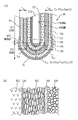
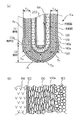
図1を参照して、本発明の第1の実施形態におけるガスセンサ素子10について説明する。本図(a)は、ガスセンサ素子10の要部全体を示す断面図、(b)は、境界部103における拡大断面図である。
ガスセンサ素子10は、固体電解質体100と、基準電極110と、測定電極120と、コーティング層130と、触媒層140と、被毒層150とによって構成されている。
固体電解質体100は、例えばジルコニア等の酸素イオン伝導性のある固体電解質材料を略有底筒状に形成してあり、その先端側には、ガスセンサ素子10の軸方向に平行な断面である軸断面における輪郭線が直線である脚部101と輪郭線が曲線である底部102とが形成されている。
固体電解質体100の内側面と外側面とには、Pt等の導電性材料を用いて基準電極110と、測定電極120とが形成されている。
本実施形態において、測定電極120は脚部101の表面と底部102の表面とを覆う全面電極によって構成されている。
固体電解質体100の外側面を測定電極120ごと覆いつつ被測定ガスを透過させるとともに貴金属触媒を担持する電極保護層として、アルミナ、アルミナマグネシアスピネル、チタニアの少なくともいずれか一種を主成分とする金属酸化物を用いて測定電極110の表面を覆うようにコーティング層130が形成され、さらにその外表面を覆うとともに、アルミナ、アルミナマグネシアスピネル、ジルコニアの少なくともいずれか一種を主成分とする金属酸化物と、Pt、Pd、Rh、Ruの少なくともいずれか一種を主成分とする貴金属触媒とによって触媒層140が形成され、さらにその外表面を覆うように、アルミナ、アルミナマグネシアスピネル、チタニアの少なくともいずれか一種を主成分とする金属酸化物を用いて被毒層150が設けられている。
固体電解質体100の内側には、通電により発熱するヒータ200が挿通される。
The gas sensor element and the gas sensor according to the present invention detect the concentration of a specific gas component such as oxygen or nitrogen oxide contained in combustion exhaust discharged from an internal combustion engine such as an automobile engine as a gas to be measured. Is used for feedback control of combustion conditions, failure diagnosis of the combustion exhaust gas purification device, and the like, and is used as an oxygen sensor, λ sensor, NOx sensor, and the like.
With reference to FIG. 1, the
The
The
A
In the present embodiment, the
Metal oxide mainly composed of at least one of alumina, alumina magnesia spinel, and titania as an electrode protective layer that allows the gas to be measured to pass through while covering the outer surface of the
Inside the
本実施形態においては、固体電解質体100の底部102と脚部101との境界部103に設けた保護層140の膜厚TA1、TA3、及び/又は、底部102に設けた保護層140の膜厚TA(=(TA1+TA2+TA3)/3)を、脚部101に設けた膜厚TB(=(TB1+TB2)/2)よりも大きく形成してある。
具体的には、電極保護層130、140、150は、底部102における膜厚を底部膜厚TAとし、脚部101における膜厚を脚部膜厚TBとし、底部膜厚TAに対する脚部膜厚TBの比を膜厚比TA/TBと定義したとき、本実施形態においては、測定電極120が全面電極であるので、膜厚比TA/TBを1.5以上2.5以下に設定してある。
本実施形態においては、固体電解質体100の内側に挿入されたヒータ200により加熱されたときに、固体電解質体100の底部102と脚部101との境界部103、及び/又は、底部102が昇温速度の速い部位となる。
In the present embodiment, the film thickness T A1 and T A3 of the
Specifically, the
In the present embodiment, when heated by the
本実施形態におけるガスセンサ素子10の製造方法の概要について説明する。
固体電解質体100は、イットリアを所定量点火したジルコニア造粒粉末を用いて、押出成形、加圧成型、CIP、HIP等の公知の方法により、一端が閉塞し、他端が開放する略有底筒状に形成した後、これを1400〜1600℃で焼成することによって形成できる。
基準電極110及び測定電極120は、Ptを用いて、その内外に蒸着や化学メッキ等の公知の方法により形成できる。
次いで、測定電極120の表面に、アルミナ、アルミナマグネシアスピネル、チタニアの少なくともいずれか一種を主成分とする金属酸化物を用いて、スラリー若しくはペーストの塗布、グリーンシートの貼り付け、焼成、プラズマ溶射等の公知の方法により測定電極120に直接接触する最下層部としてコーティング層130を形成することができる。
さらに、アルミナ、アルミナマグネシアスピネル、ジルコニアの少なくともいずれか一種を主成分とする金属酸化物と、Pt、Pd、Rh、Ruの少なくともいずれか一種を主成分とする貴金属触媒とを用いて、触媒層形成用スラリーを作成し、これにコーティング層130を形成した固体電解質体100を浸漬、乾燥、焼成することによって触媒層140を形成することができる。
このとき、脚部101と底部102との境界部103、及び/又は、底部102を触媒層形成用スラリーに浸漬する回数を多くしたり、スラリーからの引上げ速度を調整したりすることによって、触媒層140の膜厚を調整することが可能となり、脚部101と底部102との境界部103、及び/又は、底部102における触媒層140中に含まれる貴金属触媒の量を脚部101における触媒層140中に含まれる貴金属触媒の量よりも多くすることができる。
An outline of a manufacturing method of the
The
The
Next, on the surface of the
Furthermore, a catalyst layer using a metal oxide mainly composed of at least one of alumina, alumina magnesia spinel and zirconia, and a noble metal catalyst mainly composed of at least one of Pt, Pd, Rh and Ru. The
At this time, by increasing the number of times that the
なお、触媒層140を形成するに際して、予めアルミナ等の耐熱性金属酸化物粒子に触媒金属塩の溶液を含浸させ、乾燥、熱処理して、耐熱性金属酸化物の粒子表面に貴金属触媒を析出させるとともに粒成長させたものを用いても良い。
触媒層140を形成した後、アルミナ、アルミナマグネシアスピネル、ジルコニアの少なくともいずれか一種を主成分とする金属酸化物を用いて、スラリーを作成し、これに触媒層140を形成した固体電解質体100を浸漬し、乾燥し、焼成する等の公知の方法により、被毒層150を形成すれば、ガスセンサ素子10を得ることができる。
さらに、被毒層150を形成するに際して、アルミナゾル、シリカゾル等の無機バインダーを含むものを用いても良い。
本実施形態においては、脚部101に設けた触媒層140の貴金属触媒の担持率PBと、底部102に設けた触媒層140の貴金属触媒担持率PAとが、等しく設定してあり、膜厚の調整によって、触媒量に差を設けてある。
また、本実施形態に示すように、電極保護層を、コーティング層130と触媒層140と、被毒層150との三層によって構成しても良いし、後述するように、貴金属触媒を直接担持するコーティング層130aと被毒層150との二層によって構成しても良い。
In forming the
After forming the
Further, when the
In the present embodiment, the supporting ratio P B of the noble metal catalyst of the
Further, as shown in the present embodiment, the electrode protective layer may be constituted by three layers of a
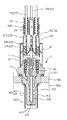
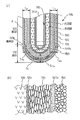
図2を参照して、本発明の第1の実施形態におけるガスセンサ素子10を有するガスセンサ1の概要について説明する。
図2に示すように、ガスセンサ1は、ガスセンサ素子10の内側にヒータ20が挿入保持され、ガスセンサ素子10を内側に挿通保持するハウジング30と、ハウジング30の基端側に配設され、ガスセンサ素子10の基端側を覆う大気側カバー31と、ハウジング30の先端側に配設されガスセンサ素子10の先端側を覆う素子カバー40とを有する。
ハウジング30は、被測定ガス500が流れる被測定ガス流路50の壁面に固定され、ガスセンサ素子10の先端を被測定ガス中に保持固定している。
ガスセンサ素子10は略筒状に形成された金属製のハウジング30の内面側に封止部材301等を介して固定されている。
ハウジング30の基端側開口部には、大気側カバー31が固定されている。
ハウジング30の先端側開口部には、素子カバー40が固定されている。
素子カバー40は、内側カバー41と外側カバー42とによって構成された二重筒構造となっており、それぞれの側面と底面とに開口411、412、421、422が設けられており、ガスセンサ素子10への被水を防止しつつ、被測定ガス500をガスセンサ素子10の先端側に導入する構造となっている。
With reference to FIG. 2, the outline | summary of the
As shown in FIG. 2, the
The
The
An atmosphere-
An element cover 40 is fixed to the opening on the front end side of the
The element cover 40 has a double cylinder structure constituted by an inner cover 41 and an outer cover 42, and
ガスセンサ素子10の内側には、略筒状のヒータ保持金具111を介して、通電により発熱するヒータ200が弾性的に把持されている。
ヒータ保持金具111は、固体電解質体100の内側に設けた基準電極110と電気的に接続された基準電極端子を兼ねており、さらに、端子金具112、信号線113を介して外部に設けた図略の検出手段に接続されている。
ガスセンサ素子10の基端外周には、略環状の測定電極端子121が嵌着されており、さらに、端子金具122、信号線123を介して外部に設けた図略の検出手段に接続されている。
ヒータ200の基端側には、導通端子210、220が設けられており、端子金具211、221が電気的に接続され、さらに、接続金具212、222、通電線213、223を介して外部に設けた図略の通電制御装置に接続されている。
大気側カバー31内には絶縁碍子32が弾性的に保持されており、絶縁碍子32は、端子金具112、122、212、222を絶縁固定している。
大気カバー31の基端側は、弾性部材33を介して、信号線113、123、通電線213、223を固定しつつ、封止されている。
大気カバー31及び弾性部材33には、大気導入孔330が設けられており、撥水フィルタ34を介して、ガスセンサ素子10の内側に設けた基準電極110の表面に基準ガスとして大気を導入する構造となっている。
Inside the
The
A substantially annular
Conductive terminals 210 and 220 are provided on the base end side of the
An
The base end side of the
The
例えば、ガスセンサ1を酸素センサとして使用する場合、基準電極110の表面に接触する大気中に含まれる酸素の濃度と測定電極120の表面に接触する被測定ガス500中に含まれる酸素の濃度との差によって、濃淡電池が形成され、基準電極110と測定電極120との間の起電力を測定することによって被測定ガス中の酸素濃度や、窒素酸化物濃度を知ることができる。
このとき、本発明のガスセンサ1では、ヒータ200によって加熱されたときの昇温速度の速い部位である底部102に設けられた電極保護層130、140、150に含まれる貴金属触媒の量が、昇温速度の遅い部位である脚部101に設けられた電極保護層130、140、150に含まれる貴金属触媒の量より多いので、始動時には、底部102に設けた貴金属触媒による水素の浄化が支配的となり、λ点のズレが抑制され、ガスセンサ素子10全体の温度が上昇し、安定化した状態では、脚部101に設けられた電極保護層130、140、150中の貴金属触媒の量が少ないので、触媒に吸着される被測定ガス50が少なくなり、拡散速度が低下せず、高い応答性を維持できる。
For example, when the
At this time, in the
本実施形態においては、電極保護層の内、触媒層140の膜厚を任意に調整することが可能で、底部膜厚TAを脚部膜厚TBより厚く形成することにより、ヒータ200により加熱されたときの昇温速度の速い位置ほど電極保護層に含まれる貴金属触媒の量を多くし、ヒータ200により加熱されたときの昇温速度の遅い位置ほど電極保護層に含まれる貴金属触媒の量を少なくしたガスセンサ素子10の製造が容易である。
In the present embodiment, among the electrode protective layer, it can be arbitrarily adjusted thickness of the
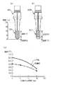
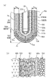
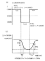
また、固体電解質体100の外側表面に形成される測定電極は、図3(a)に示すように、底部101と脚部102との全面に渡って設けられる全面電極120によって構成してもよいし、本図(b)に示す固体電解質体100Pとして、図3(b)に示すように、脚部101の表面にのみに設けられる部分電極120Pによって構成しても良い。
いずれの場合も、固体電解質体100、100Pの表面の温度は、本図(c)に示すように、先端部が最も高くなり、基端側に向かって徐々に温度が低くなっている。
特に、始動時には、固体電解質体100の表面の温度は、先端側の底部102付近では400℃以上となり、固体電解質体100の酸素イオン伝導性が発揮され、触媒層140に含まれる貴金属触媒も活性を示すが、脚部101付近は、温度が低く、酸素イオン導電性を発揮せず、被測定ガス中の酸素イオン濃度の検出に寄与しない。
Further, the measurement electrode formed on the outer surface of the
In any case, the temperature of the surface of the
In particular, at the time of starting, the temperature of the surface of the
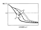
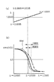
ここで、図4を参照して、電極保護層中に含まれる触媒担持量とガスセンサの応答性との関係について説明する。
図4は、水素濃度を一定とし、酸素濃度を変化させたガスを被測定ガスとして用いて、λを0.9995から1.0005まで連続的に変化させたときの出力応答について、触媒担持量を変えた従来構造のガスセンサを用いた場合の特性を示す。
図4に示すように、触媒担持量が多くなると、応答時間の遅れが大きくなる。これは、触媒粒子に被測定ガス中の酸素が吸着され、拡散速度が低下するためと推察される。
触媒担持量を少なくすれば、応答性は向上すると推察されるが、始動時等水素の存在量が多い場合には、触媒による水素の浄化が不十分となり、水素の影響によりλ点ズレが大きくなると推察される。
本発明は、このような二律背反する課題を解決すべくなされたものである。
Here, with reference to FIG. 4, the relationship between the catalyst carrying amount contained in an electrode protective layer and the responsiveness of a gas sensor is demonstrated.
FIG. 4 shows the catalyst loading with respect to the output response when λ is continuously changed from 0.9995 to 1.0005 using a gas with a constant hydrogen concentration and a changed oxygen concentration as the gas to be measured. The characteristic at the time of using the gas sensor of the conventional structure which changed is shown.
As shown in FIG. 4, as the catalyst loading increases, the response time delay increases. This is presumably because oxygen in the gas to be measured is adsorbed on the catalyst particles, and the diffusion rate decreases.
If the amount of catalyst supported is reduced, it is assumed that the response will be improved. However, if the amount of hydrogen present at startup is large, hydrogen purification by the catalyst will be insufficient, and the λ point deviation will be large due to the influence of hydrogen. It is assumed that
The present invention has been made to solve such a contradictory problem.
図5を参照して本発明の第2の実施形態におけるガスセンサ素子10aについて説明する。なお、上記実施形態と同じの構成については、同じ符号を付したので説明を省略し、本実施形態における特徴的な点についてのみ説明する(以下の実施形態について同様とする)。
第1の実施形態では、コーティング層130を形成した後、触媒層140をその外表面に形成したが、図5に示すように、本実施形態においては、コーティング層130aに直接貴金属触媒140aを担持させている。
具体的には、アルミナ等を用いてプラズマ溶射等の公知の方法によりコーティング層130aを形成した後、例えば、H2PtCl6等の触媒金属塩水溶液に浸漬し、減圧下でコーティング層130a内に触媒金属塩を浸透させ、これを乾燥、焼成したり、予め、耐熱性金属酸化物の表面に貴金属粒子を析出、粒成長させたものを用いてコーティング層130aを形成したりしても良い。
このような構成においても、電極保護層130a、140a、150の底部膜厚TAを脚部膜厚TBよりも厚くすることによって、ヒータ200によって昇温されやすい底部102における電極保護層130a、140a、150中の貴金属触媒の量を多くすることができ、第1の実施形態と同様の効果を発揮できる。
A
In the first embodiment, after forming the
Specifically, after forming the
In such a configuration, the electrode
図6を参照して、本発明の第3の実施形態におけるガスセンサ素子10bについて説明する。上記実施形態においては、電極保護層130、140、150の膜厚調整によって貴金属触媒の担持量を調整したが、本実施形態においては、脚部101と底部102とで触媒担持率を変化させることにより、貴金属触媒の担持量を調整している。
具体的には、 底部102と脚部102との境界部103、及び/又は、底部102に設けた電極保護層130、140b、150の貴金属触媒の担持率PAを、脚部102に設け電極保護層の貴金属触媒の担持率PBよりも大きく設定してある。
より具体的には、底部102における触媒担持率を底部担持率PAとし、脚部101における触媒担持率を脚部担持率PBとし、底部担持率PAに対する脚部担持率PBの比を担持率比PA/PBと定義したとき、本実施形態においては、測定電極120が全面電極であるので、担持率比PA/PBを1.6以上、2.3以下となるように設定してある。
なお、触媒担持率は、ガスセンサ素子10bを切断し、破断面におけるSEM分析観察等によって算出できる。
具体的には、反射電子像によって、1万〜数万倍の画像を利用し、のべ面積で10μm2以上の領域を観察し、白色粒子として観察される貴金属触媒の粒子について円相当径を画像処理等により算出し、これを球状粒子とみなして、重量換算し、単位面積当たりの重さを触媒担持率とした。
また、底部担持率PAは、境界部103の4カ所と底部102bの膜厚TA2bの2カ所を観察し、その平均担持率を算出し、脚部担持率PBは、境界部103から5mmの位置で4カ所を観察し、その平均担持率を算出した。
With reference to FIG. 6, the gas sensor element 10b in the 3rd Embodiment of this invention is demonstrated. In the above embodiment, the loading amount of the noble metal catalyst is adjusted by adjusting the film thickness of the electrode
Specifically, the
More specifically, the catalyst supporting ratio at the bottom 102 and the bottom support ratio P A, a catalyst-supporting ratio in the
The catalyst loading rate can be calculated by cutting the gas sensor element 10b and observing the fractured surface with SEM analysis or the like.
Specifically, by using a backscattered electron image, an image of 10,000 to several tens of thousands of times is used, a total area of 10
Further, the bottom carrying rate P A is observed at two places of the
さらに、脚部101と底部102とで触媒担持率を変化させるためには、貴金属触媒の含有量の多いスラリーを用いて底部102に塗布、乾燥、焼成した後、貴金属触媒の含有量の少ないスラリーを用いて脚部101に塗布、乾燥、焼成することにより、触媒層140bを形成することができる。
或いは、コーティング層130bに直接貴金属触媒を担持させる場合には、底部102に設けたコーティング層130bと脚部101と設けたコーティング層130とを触媒金属塩水溶液に浸漬した後、底部102に設けたコーティング層130のみ、複数回触媒金属塩水溶液に浸漬することにより、底部102の貴金属触媒の担持量を増やすこともできる。
Further, in order to change the catalyst loading ratio between the
Alternatively, when the noble metal catalyst is directly supported on the coating layer 130b, the coating layer 130b provided on the bottom 102 and the
図7を参照して、本発明の第4の実施形態におけるガスセンサ素子10bについて説明する。上記実施形態においては、測定電極120が全面電極である場合について説明したが、本実施形態においては、測定電極120cが部分電極である点が相違している。
このため、膜厚比TA/TBを1.5以上、2.0以下に設定してある。
又は、担持率比PA/PBを1.7以上、2.0以下に設定しても良い。
さらに、これらを組み合わせて、膜厚比TA/TBを1.5以上、2.0以下以下とし、かつ、担持率比PA/PBを1.7以上、2.0以下に設定しても良い。
With reference to FIG. 7, the gas sensor element 10b in the 4th Embodiment of this invention is demonstrated. In the above-described embodiment, the case where the
Therefore, the film thickness ratio T A / T B of 1.5 or more, is set to 2.0 or less.
Alternatively, the loading ratio P A / P B may be set to 1.7 or more and 2.0 or less.
Furthermore, by combining these, the film thickness ratio T A / T B is set to 1.5 or more and 2.0 or less, and the support ratio P A / P B is set to 1.7 or more and 2.0 or less. You may do it.
図8、図9を参照し、本発明の効果を確認するために行った試験方法について説明する。
図8(a)に示すように、水素濃度を一定とし、酸素濃度を変化させたガスを被測定ガスとして用いて、λを0.9995から1.0005まで連続的に変化させ、そのときのセンサ出力について、本図(b)に示すように、λ=1.000からのλ点のズレについて、電極保護層の膜厚を変化させて、試験調査を行った。
また、図9(a)に示すように、被測定ガスとして、空燃比が0.9995となるように、一酸化炭素CO、メタンCH4、プロパンC3H8を混合したリッチガスと、空燃比が1.0005となるように酸素O2、窒素酸化物NOとを混合したリーンガスとを所定の周期で入れ換え、本図(b)に示すように、センサ出力が63%応答を示すときの、リッチリーン反転応答時間TRLとリーンリッチ反転応答時間TLRとの平均値を計測して、電極保護層の膜厚を変化させて、ステップ応答性について試験調査を行った。
With reference to FIG. 8 and FIG. 9, the test method performed in order to confirm the effect of this invention is demonstrated.
As shown in FIG. 8 (a), λ is continuously changed from 0.9995 to 1.0005 using a gas with a constant hydrogen concentration and a changed oxygen concentration as a gas to be measured. As for the sensor output, as shown in FIG. 4B, a test investigation was performed by changing the film thickness of the electrode protective layer with respect to the deviation of the λ point from λ = 1.000.
Further, as shown in FIG. 9A, the gas to be measured is a rich gas in which carbon monoxide CO, methane CH4, and propane C 3 H8 are mixed so that the air-fuel ratio becomes 0.9995, and the air-fuel ratio is 1 Rich lean inversion when the sensor output shows a 63% response as shown in FIG. 5B by replacing the lean gas mixed with
その結果を表1及び表2に示す。
表1は、測定電極120として、全面電極を用いた場合、表2は、測定電極120Pとして部分電極を用いた場合を示す。
比較例1として用いた、脚部101の脚部膜厚TBと底部102の底部膜厚TAとが等しい場合において、出力電圧が0.5vのときのλ点ズレ量が0.0009であったので、λ点が1.001より大きい場合は効果なしと評価し、判定結果を△印で示し、λ点が1.001以下で、1.0005より大きい場合は、効果ありと評価し、判定結果を○印で示し、λ点が1.005以下となった場合を効果大と評価し、判定結果を◎印で示した。
比較例1として用いた、脚部101の脚部膜厚TBと底部102の底部膜厚TAとが等しい場合のステップ応答時間が15秒であったので、ステップ応答時間が15秒より長い場合は効果なしと評価し、判定結果を△印で示し、ステップ応答時間が15秒以下の場合は効果ありと評価し、判定結果を○印で示した。
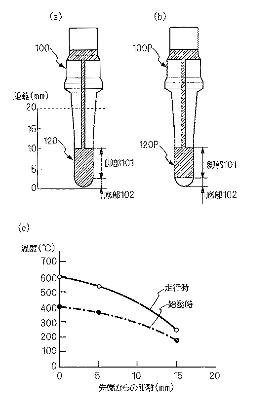
Table 1 shows a case where a full-surface electrode is used as the
Was used as comparative example 1, when the bottom thickness T A of the leg thickness T B and the
Was used as Comparative Example 1, since the step response time when the bottom thickness T A of the leg thickness T B and the
同様の試験を、電極保護層130、140、150に含まれる貴金属触媒の担持率を変化させて行った結果を表3、表4に示す。 表3は、測定電極120として、全面電極を用いた場合、表4は、測定電極120Pとして部分電極を用いた場合を示す。
比較例1として用いた、脚部101の脚部触媒担持率PBと底部102の底部触媒担持率PAとが等しい場合において、出力電圧が0.5vのときのλ点ズレ量が0.0009であったので、λ点が1.001より大きい場合は効果なしと評価し、判定結果を△印で示し、λ点が1.001以下で、1.0005より大きい場合は、効果ありと評価し、判定結果を○印で示し、λ点が1.005以下となった場合を効果大と評価し、判定結果を◎印で示した。
比較例1として用いた、脚部101の脚部触媒担持率PBと底部102の底部触媒担持率PAとが等しい場合のステップ応答時間が15秒であったので、ステップ応答時間が15秒より長い場合は効果なしと評価し、判定結果を△印で示し、ステップ応答時間が15秒以下の場合は効果ありと評価し、判定結果を○印で示した。
Was used as comparative example 1, when a bottom catalyst supporting ratio P A leg catalyst supporting ratio P B and the
Was used as Comparative Example 1, since the step response time for the bottom catalyst supporting ratio P A leg catalyst supporting ratio P B and the
1 ガスセンサ
10 ガスセンサ素子100 固体電解質体
101 底部
102 脚部
110 基準電極
120 測定電極
130 コーティング層(電極保護層)
140 触媒層(電極保護層)
150 被毒層(電極保護層)
200 ヒータ
TA 底部膜厚((TA1+TA2+TA2)/3)
TB 脚部膜厚((TB1+TB2)/2)
PA 底部担持率
PB 脚部担持率
DESCRIPTION OF
140 Catalyst layer (electrode protective layer)
150 Poisoned layer (electrode protective layer)
200 Heater T A bottom film thickness ((T A1 + T A2 + T A2 ) / 3)
T B AshibumakuAtsu ((T B1 + T B2) / 2)
P A bottom supporting ratio P B leg supporting ratio
Claims (7)
先端側には、このガスセンサ素子の軸方向に平行な断面である軸断面における輪郭線が直線である脚部と、上記輪郭線が曲線である底部とが形成されており、
上記測定電極が上記脚部の表面と上記底部の表面とを覆う全面電極、又は、上記測定電極が上記脚部の表面のみを覆い、上記底部の表面を覆わない部分電極のいずれかからなり、上記ヒータにより加熱されたときの昇温速度の速い部位ほど上記電極保護層に含まれる上記貴金属触媒の量を多くし、上記ヒータにより加熱されたときの昇温速度の遅い部位ほど上記電極保護層に含まれる上記貴金属触媒の量を少なくしたことを特徴とするガスセンサ素子。 At least a bottomed cylindrical oxygen ion conductive solid electrolyte body, a reference electrode disposed on the inner surface of the solid electrolyte body, a measurement electrode disposed on the outer surface of the solid electrolyte body, and the solid electrolyte A gas sensor element having an electrode protective layer that allows a gas to be measured to pass through while covering the outer surface of the body together with the measurement electrode and that carries a noble metal catalyst, and a heater that is inserted inside the solid electrolyte body and generates heat when energized. ,
On the distal end side, a leg portion having a straight contour line in an axial cross section that is a cross section parallel to the axial direction of the gas sensor element and a bottom portion having a curved contour line are formed,
The measurement electrode consists of either a full-surface electrode that covers the surface of the leg and the surface of the bottom, or a partial electrode that covers only the surface of the leg and does not cover the surface of the bottom, The higher the temperature rising rate when heated by the heater, the greater the amount of the noble metal catalyst contained in the electrode protective layer, and the lower the temperature rising rate when heated by the heater, the electrode protective layer. A gas sensor element characterized in that the amount of the noble metal catalyst contained in the catalyst is reduced.
上記電極保護層の最下層部の外表面を覆うとともに、
アルミナ、アルミナマグネシアスピネル、ジルコニアの少なくともいずれか一種を主成分とする金属酸化物と、
Pt、Pd、Rh、Ruの少なくともいずれか一種を主成分とする貴金属触媒とによって触媒層を形成した請求項1ないし5のいずれか1項に記載のガスセンサ素子。 The electrode protective layer is formed of at least two layers, and the lowermost layer part in direct contact with the measurement electrode of the electrode protective layer is a metal oxide mainly composed of at least one of alumina, alumina magnesia spinel, and titania. Formed by things,
While covering the outer surface of the lowermost layer portion of the electrode protective layer,
A metal oxide mainly composed of at least one of alumina, alumina magnesia spinel, and zirconia;
The gas sensor element according to any one of claims 1 to 5, wherein a catalyst layer is formed of a noble metal catalyst mainly composed of at least one of Pt, Pd, Rh, and Ru.
このガスセンサ素子を内側に挿通保持するハウジングと、このハウジングの基端側に配設され上記ガスセンサ素子の基端側を覆う大気側カバーと、上記ハウジングの先端側に配設され上記ガスセンサ素子の先端側を覆う素子カバーとを有するガスセンサ。 A gas sensor for detecting a concentration of a specific gas component in a gas to be measured, wherein the gas sensor element according to any one of claims 1 to 6,
A housing for inserting and holding the gas sensor element on the inside, an atmosphere-side cover disposed on the proximal end side of the housing and covering the proximal end side of the gas sensor element, and a distal end of the gas sensor element disposed on the distal end side of the housing A gas sensor having an element cover covering the side.
Priority Applications (4)
| Application Number | Priority Date | Filing Date | Title |
|---|---|---|---|
| JP2010110780A JP5182321B2 (en) | 2010-05-13 | 2010-05-13 | Gas sensor element and gas sensor incorporating the same |
| DE102011075755.4A DE102011075755B4 (en) | 2010-05-13 | 2011-05-12 | Gas sensing element and gas sensor equipped therewith |
| US13/106,979 US8597481B2 (en) | 2010-05-13 | 2011-05-13 | Gas sensor element and gas sensor equipped with the same |
| CN201110128522.6A CN102243211B (en) | 2010-05-13 | 2011-05-13 | Gas sensor element and gas sensor equipped with the same |
Applications Claiming Priority (1)
| Application Number | Priority Date | Filing Date | Title |
|---|---|---|---|
| JP2010110780A JP5182321B2 (en) | 2010-05-13 | 2010-05-13 | Gas sensor element and gas sensor incorporating the same |
Publications (2)
| Publication Number | Publication Date |
|---|---|
| JP2011237356A true JP2011237356A (en) | 2011-11-24 |
| JP5182321B2 JP5182321B2 (en) | 2013-04-17 |
Family
ID=44910800
Family Applications (1)
| Application Number | Title | Priority Date | Filing Date |
|---|---|---|---|
| JP2010110780A Active JP5182321B2 (en) | 2010-05-13 | 2010-05-13 | Gas sensor element and gas sensor incorporating the same |
Country Status (4)
| Country | Link |
|---|---|
| US (1) | US8597481B2 (en) |
| JP (1) | JP5182321B2 (en) |
| CN (1) | CN102243211B (en) |
| DE (1) | DE102011075755B4 (en) |
Cited By (3)
| Publication number | Priority date | Publication date | Assignee | Title |
|---|---|---|---|---|
| JP2014178179A (en) * | 2013-03-14 | 2014-09-25 | Toyota Motor Corp | Gas sensor and manufacturing method thereof |
| WO2015076194A1 (en) * | 2013-11-22 | 2015-05-28 | 株式会社デンソー | Oxygen sensor element |
| JP2016029360A (en) * | 2014-07-18 | 2016-03-03 | トヨタ自動車株式会社 | Gas sensor element |
Families Citing this family (8)
| Publication number | Priority date | Publication date | Assignee | Title |
|---|---|---|---|---|
| CN103529102A (en) * | 2013-10-25 | 2014-01-22 | 郑龙华 | Multi-layer composite protective layer of oxygen sensor and manufacturing method thereof |
| JP6350326B2 (en) * | 2014-06-30 | 2018-07-04 | 株式会社デンソー | Gas sensor |
| JP6478719B2 (en) * | 2015-03-06 | 2019-03-06 | 株式会社Soken | Gas sensor element and gas sensor |
| DE102016217775A1 (en) * | 2016-09-16 | 2018-03-22 | Robert Bosch Gmbh | Sensor element for detecting particles of a measuring gas in a measuring gas chamber |
| JP6809355B2 (en) * | 2017-04-18 | 2021-01-06 | 株式会社デンソー | Gas sensor |
| JP6880179B2 (en) * | 2017-12-28 | 2021-06-02 | 日本特殊陶業株式会社 | Gas sensor element and gas sensor |
| JP6919996B2 (en) * | 2018-02-06 | 2021-08-18 | トヨタ自動車株式会社 | Gas sensor element |
| CN108585801A (en) * | 2018-06-06 | 2018-09-28 | 成都科锐传感技术有限公司 | A kind of porous external protection preparation method improving chip oxygen sensor saltus step offset |
Citations (7)
| Publication number | Priority date | Publication date | Assignee | Title |
|---|---|---|---|---|
| JPH01153953A (en) * | 1987-12-11 | 1989-06-16 | Ngk Spark Plug Co Ltd | Element for oxygen sensor |
| JPH0197855A (en) * | 1987-07-31 | 1989-07-28 | Ngk Spark Plug Co Ltd | Oxygen detecting element |
| JPH01203963A (en) * | 1988-02-10 | 1989-08-16 | Ngk Spark Plug Co Ltd | Oxygen sensor element |
| JPH01245147A (en) * | 1988-03-28 | 1989-09-29 | Ngk Spark Plug Co Ltd | Oxygen sensor element |
| JPH11237361A (en) * | 1997-12-15 | 1999-08-31 | Nippon Soken Inc | Gas sensor |
| JP2002181769A (en) * | 2000-10-05 | 2002-06-26 | Denso Corp | Oxygen sensor element and production method thereof |
| JP2003107047A (en) * | 2001-10-01 | 2003-04-09 | Denso Corp | Gas-concentration detecting element |
Family Cites Families (6)
| Publication number | Priority date | Publication date | Assignee | Title |
|---|---|---|---|---|
| US5538612A (en) * | 1987-12-09 | 1996-07-23 | Ngk Spark Plug Co., Ltd. | Oxygen sensor element |
| DE4004172C2 (en) * | 1989-02-14 | 1998-06-04 | Ngk Spark Plug Co | An oxygen sensor for air-fuel mixture control having a protective layer comprising an oxygen occluding substance, and a method of manufacturing the sensor |
| JP4269765B2 (en) | 2003-05-01 | 2009-05-27 | 株式会社デンソー | Multilayer gas sensor element |
| JP2006038496A (en) | 2004-07-22 | 2006-02-09 | Ngk Spark Plug Co Ltd | Gas sensor and manufacturing method therefor |
| JP2010110780A (en) | 2008-11-05 | 2010-05-20 | Marugo Rubber Ind Co Ltd | Drawing device for bush |
| JP4831164B2 (en) | 2008-12-25 | 2011-12-07 | 株式会社デンソー | Gas sensor element and gas sensor incorporating the same |
-
2010
- 2010-05-13 JP JP2010110780A patent/JP5182321B2/en active Active
-
2011
- 2011-05-12 DE DE102011075755.4A patent/DE102011075755B4/en active Active
- 2011-05-13 CN CN201110128522.6A patent/CN102243211B/en active Active
- 2011-05-13 US US13/106,979 patent/US8597481B2/en active Active
Patent Citations (7)
| Publication number | Priority date | Publication date | Assignee | Title |
|---|---|---|---|---|
| JPH0197855A (en) * | 1987-07-31 | 1989-07-28 | Ngk Spark Plug Co Ltd | Oxygen detecting element |
| JPH01153953A (en) * | 1987-12-11 | 1989-06-16 | Ngk Spark Plug Co Ltd | Element for oxygen sensor |
| JPH01203963A (en) * | 1988-02-10 | 1989-08-16 | Ngk Spark Plug Co Ltd | Oxygen sensor element |
| JPH01245147A (en) * | 1988-03-28 | 1989-09-29 | Ngk Spark Plug Co Ltd | Oxygen sensor element |
| JPH11237361A (en) * | 1997-12-15 | 1999-08-31 | Nippon Soken Inc | Gas sensor |
| JP2002181769A (en) * | 2000-10-05 | 2002-06-26 | Denso Corp | Oxygen sensor element and production method thereof |
| JP2003107047A (en) * | 2001-10-01 | 2003-04-09 | Denso Corp | Gas-concentration detecting element |
Cited By (4)
| Publication number | Priority date | Publication date | Assignee | Title |
|---|---|---|---|---|
| JP2014178179A (en) * | 2013-03-14 | 2014-09-25 | Toyota Motor Corp | Gas sensor and manufacturing method thereof |
| WO2015076194A1 (en) * | 2013-11-22 | 2015-05-28 | 株式会社デンソー | Oxygen sensor element |
| JP2015102384A (en) * | 2013-11-22 | 2015-06-04 | 株式会社デンソー | Oxygen sensor element |
| JP2016029360A (en) * | 2014-07-18 | 2016-03-03 | トヨタ自動車株式会社 | Gas sensor element |
Also Published As
| Publication number | Publication date |
|---|---|
| US8597481B2 (en) | 2013-12-03 |
| JP5182321B2 (en) | 2013-04-17 |
| CN102243211A (en) | 2011-11-16 |
| CN102243211B (en) | 2014-07-09 |
| DE102011075755A1 (en) | 2012-03-08 |
| DE102011075755B4 (en) | 2022-10-06 |
| US20110278169A1 (en) | 2011-11-17 |
Similar Documents
| Publication | Publication Date | Title |
|---|---|---|
| JP5182321B2 (en) | Gas sensor element and gas sensor incorporating the same | |
| JP2514701B2 (en) | Oxygen sensor | |
| JP4595264B2 (en) | Oxygen sensor element and manufacturing method thereof | |
| JP4587473B2 (en) | Gas sensor | |
| JP6857051B2 (en) | Gas sensor element and gas sensor | |
| JP6867921B2 (en) | Ammonia concentration measuring device, ammonia concentration measuring system, exhaust gas treatment system, and ammonia concentration measuring method | |
| JP5187417B2 (en) | Gas sensor element and manufacturing method thereof | |
| US6210552B1 (en) | Oxygen sensor | |
| US20130062203A1 (en) | Ammonia gas sensor | |
| JP2006038496A (en) | Gas sensor and manufacturing method therefor | |
| US20010040092A1 (en) | Gas sensor | |
| JP6702342B2 (en) | Gas sensor | |
| JP4496104B2 (en) | Gas sensor evaluation method and gas sensor evaluation apparatus | |
| JP2012037509A (en) | Ammonia gas sensor | |
| JP6943575B2 (en) | Gas sensor | |
| JP5124500B2 (en) | Catalyst powder for gas sensor, method for producing the same, gas sensor element using the same, and gas sensor using the same | |
| JP6907687B2 (en) | Gas sensor | |
| JPH05322844A (en) | Hydrogen carbide concentration measuring method and device | |
| JP4750574B2 (en) | Gas detection element | |
| JP6966360B2 (en) | Gas sensor element and gas sensor | |
| JP6872476B2 (en) | Sensor element and gas sensor | |
| JP5271978B2 (en) | Ammonia gas sensor | |
| JP6885885B2 (en) | Gas sensor element and gas sensor | |
| JPH0778483B2 (en) | Oxygen detector | |
| JP2014021032A (en) | Method of manufacturing gas sensor |
Legal Events
| Date | Code | Title | Description |
|---|---|---|---|
| A621 | Written request for application examination |
Free format text: JAPANESE INTERMEDIATE CODE: A621 Effective date: 20110912 |
|
| A977 | Report on retrieval |
Free format text: JAPANESE INTERMEDIATE CODE: A971007 Effective date: 20120412 |
|
| A131 | Notification of reasons for refusal |
Free format text: JAPANESE INTERMEDIATE CODE: A131 Effective date: 20120424 |
|
| A131 | Notification of reasons for refusal |
Free format text: JAPANESE INTERMEDIATE CODE: A131 Effective date: 20121002 |
|
| A521 | Request for written amendment filed |
Free format text: JAPANESE INTERMEDIATE CODE: A523 Effective date: 20121122 |
|
| TRDD | Decision of grant or rejection written | ||
| A01 | Written decision to grant a patent or to grant a registration (utility model) |
Free format text: JAPANESE INTERMEDIATE CODE: A01 Effective date: 20121218 |
|
| A61 | First payment of annual fees (during grant procedure) |
Free format text: JAPANESE INTERMEDIATE CODE: A61 Effective date: 20121231 |
|
| R151 | Written notification of patent or utility model registration |
Ref document number: 5182321 Country of ref document: JP Free format text: JAPANESE INTERMEDIATE CODE: R151 |
|
| FPAY | Renewal fee payment (event date is renewal date of database) |
Free format text: PAYMENT UNTIL: 20160125 Year of fee payment: 3 |
|
| R250 | Receipt of annual fees |
Free format text: JAPANESE INTERMEDIATE CODE: R250 |
|
| R250 | Receipt of annual fees |
Free format text: JAPANESE INTERMEDIATE CODE: R250 |
|
| R250 | Receipt of annual fees |
Free format text: JAPANESE INTERMEDIATE CODE: R250 |
|
| R250 | Receipt of annual fees |
Free format text: JAPANESE INTERMEDIATE CODE: R250 |
|
| R250 | Receipt of annual fees |
Free format text: JAPANESE INTERMEDIATE CODE: R250 |
|
| R250 | Receipt of annual fees |
Free format text: JAPANESE INTERMEDIATE CODE: R250 |
|
| R250 | Receipt of annual fees |
Free format text: JAPANESE INTERMEDIATE CODE: R250 |
|
| R250 | Receipt of annual fees |
Free format text: JAPANESE INTERMEDIATE CODE: R250 |
|
| R250 | Receipt of annual fees |
Free format text: JAPANESE INTERMEDIATE CODE: R250 |