JP2011102879A - Pixel circuit, display device, and inspection method - Google Patents
Pixel circuit, display device, and inspection method Download PDFInfo
- Publication number
- JP2011102879A JP2011102879A JP2009257527A JP2009257527A JP2011102879A JP 2011102879 A JP2011102879 A JP 2011102879A JP 2009257527 A JP2009257527 A JP 2009257527A JP 2009257527 A JP2009257527 A JP 2009257527A JP 2011102879 A JP2011102879 A JP 2011102879A
- Authority
- JP
- Japan
- Prior art keywords
- voltage
- transistor
- signal
- reference potential
- line
- Prior art date
- Legal status (The legal status is an assumption and is not a legal conclusion. Google has not performed a legal analysis and makes no representation as to the accuracy of the status listed.)
- Granted
Links
- 238000000034 method Methods 0.000 title claims description 9
- 238000007689 inspection Methods 0.000 title claims description 8
- 238000005070 sampling Methods 0.000 claims abstract description 44
- 239000003990 capacitor Substances 0.000 claims description 23
- 239000000523 sample Substances 0.000 claims description 16
- 239000011159 matrix material Substances 0.000 claims description 3
- 238000010586 diagram Methods 0.000 description 15
- 238000001514 detection method Methods 0.000 description 7
- 238000002360 preparation method Methods 0.000 description 4
- 101150082606 VSIG1 gene Proteins 0.000 description 3
- 230000015572 biosynthetic process Effects 0.000 description 3
- 230000007547 defect Effects 0.000 description 3
- 238000005259 measurement Methods 0.000 description 3
- 230000002950 deficient Effects 0.000 description 2
- 230000006866 deterioration Effects 0.000 description 2
- 230000014759 maintenance of location Effects 0.000 description 1
- 230000003071 parasitic effect Effects 0.000 description 1
Images


Classifications
-
- G—PHYSICS
- G09—EDUCATION; CRYPTOGRAPHY; DISPLAY; ADVERTISING; SEALS
- G09G—ARRANGEMENTS OR CIRCUITS FOR CONTROL OF INDICATING DEVICES USING STATIC MEANS TO PRESENT VARIABLE INFORMATION
- G09G3/00—Control arrangements or circuits, of interest only in connection with visual indicators other than cathode-ray tubes
- G09G3/20—Control arrangements or circuits, of interest only in connection with visual indicators other than cathode-ray tubes for presentation of an assembly of a number of characters, e.g. a page, by composing the assembly by combination of individual elements arranged in a matrix no fixed position being assigned to or needed to be assigned to the individual characters or partial characters
-
- G—PHYSICS
- G09—EDUCATION; CRYPTOGRAPHY; DISPLAY; ADVERTISING; SEALS
- G09G—ARRANGEMENTS OR CIRCUITS FOR CONTROL OF INDICATING DEVICES USING STATIC MEANS TO PRESENT VARIABLE INFORMATION
- G09G3/00—Control arrangements or circuits, of interest only in connection with visual indicators other than cathode-ray tubes
- G09G3/006—Electronic inspection or testing of displays and display drivers, e.g. of LED or LCD displays
-
- G—PHYSICS
- G09—EDUCATION; CRYPTOGRAPHY; DISPLAY; ADVERTISING; SEALS
- G09G—ARRANGEMENTS OR CIRCUITS FOR CONTROL OF INDICATING DEVICES USING STATIC MEANS TO PRESENT VARIABLE INFORMATION
- G09G3/00—Control arrangements or circuits, of interest only in connection with visual indicators other than cathode-ray tubes
- G09G3/20—Control arrangements or circuits, of interest only in connection with visual indicators other than cathode-ray tubes for presentation of an assembly of a number of characters, e.g. a page, by composing the assembly by combination of individual elements arranged in a matrix no fixed position being assigned to or needed to be assigned to the individual characters or partial characters
- G09G3/22—Control arrangements or circuits, of interest only in connection with visual indicators other than cathode-ray tubes for presentation of an assembly of a number of characters, e.g. a page, by composing the assembly by combination of individual elements arranged in a matrix no fixed position being assigned to or needed to be assigned to the individual characters or partial characters using controlled light sources
- G09G3/30—Control arrangements or circuits, of interest only in connection with visual indicators other than cathode-ray tubes for presentation of an assembly of a number of characters, e.g. a page, by composing the assembly by combination of individual elements arranged in a matrix no fixed position being assigned to or needed to be assigned to the individual characters or partial characters using controlled light sources using electroluminescent panels
- G09G3/32—Control arrangements or circuits, of interest only in connection with visual indicators other than cathode-ray tubes for presentation of an assembly of a number of characters, e.g. a page, by composing the assembly by combination of individual elements arranged in a matrix no fixed position being assigned to or needed to be assigned to the individual characters or partial characters using controlled light sources using electroluminescent panels semiconductive, e.g. using light-emitting diodes [LED]
- G09G3/3208—Control arrangements or circuits, of interest only in connection with visual indicators other than cathode-ray tubes for presentation of an assembly of a number of characters, e.g. a page, by composing the assembly by combination of individual elements arranged in a matrix no fixed position being assigned to or needed to be assigned to the individual characters or partial characters using controlled light sources using electroluminescent panels semiconductive, e.g. using light-emitting diodes [LED] organic, e.g. using organic light-emitting diodes [OLED]
- G09G3/3225—Control arrangements or circuits, of interest only in connection with visual indicators other than cathode-ray tubes for presentation of an assembly of a number of characters, e.g. a page, by composing the assembly by combination of individual elements arranged in a matrix no fixed position being assigned to or needed to be assigned to the individual characters or partial characters using controlled light sources using electroluminescent panels semiconductive, e.g. using light-emitting diodes [LED] organic, e.g. using organic light-emitting diodes [OLED] using an active matrix
- G09G3/3233—Control arrangements or circuits, of interest only in connection with visual indicators other than cathode-ray tubes for presentation of an assembly of a number of characters, e.g. a page, by composing the assembly by combination of individual elements arranged in a matrix no fixed position being assigned to or needed to be assigned to the individual characters or partial characters using controlled light sources using electroluminescent panels semiconductive, e.g. using light-emitting diodes [LED] organic, e.g. using organic light-emitting diodes [OLED] using an active matrix with pixel circuitry controlling the current through the light-emitting element
-
- G—PHYSICS
- G09—EDUCATION; CRYPTOGRAPHY; DISPLAY; ADVERTISING; SEALS
- G09G—ARRANGEMENTS OR CIRCUITS FOR CONTROL OF INDICATING DEVICES USING STATIC MEANS TO PRESENT VARIABLE INFORMATION
- G09G2300/00—Aspects of the constitution of display devices
- G09G2300/08—Active matrix structure, i.e. with use of active elements, inclusive of non-linear two terminal elements, in the pixels together with light emitting or modulating elements
- G09G2300/0809—Several active elements per pixel in active matrix panels
- G09G2300/0842—Several active elements per pixel in active matrix panels forming a memory circuit, e.g. a dynamic memory with one capacitor
-
- G—PHYSICS
- G09—EDUCATION; CRYPTOGRAPHY; DISPLAY; ADVERTISING; SEALS
- G09G—ARRANGEMENTS OR CIRCUITS FOR CONTROL OF INDICATING DEVICES USING STATIC MEANS TO PRESENT VARIABLE INFORMATION
- G09G2310/00—Command of the display device
- G09G2310/02—Addressing, scanning or driving the display screen or processing steps related thereto
- G09G2310/0243—Details of the generation of driving signals
- G09G2310/0251—Precharge or discharge of pixel before applying new pixel voltage
Abstract
Description
駆動トランジスタを用いて発光素子を駆動する画素回路、表示装置、および検査方法に関する。 The present invention relates to a pixel circuit that drives a light emitting element using a driving transistor, a display device, and an inspection method.
有機EL素子(OLED)などの電流駆動型の発光素子を用いた表示装置では、その画素回路に駆動トランジスタを有する。この駆動トランジスタを表示信号に基づいて駆動した表示を行うが、OLEDは電流駆動素子であるため、駆動トランジスタの出力電流ばらつきは、そのまま表示品位の悪化につながる。そこで、駆動電流のばらつきを抑えることについて各種の提案があり、例えば特許文献1にその提案がある。 A display device using a current-driven light emitting element such as an organic EL element (OLED) has a drive transistor in its pixel circuit. Although display is performed by driving the drive transistor based on the display signal, since the OLED is a current drive element, variations in the output current of the drive transistor directly lead to deterioration in display quality. Therefore, there are various proposals for suppressing variation in drive current. For example, Patent Document 1 discloses the proposal.
ここで、特許文献1では、駆動電流のバラツキを押さえるためにスイッチングトランジスタを利用するが、このスイッチングトランジスタのソ−ス電極と発光素子のカソ−ド電極が共通である。このため、発光素子形成前にスイッチングトランジスタのソ−ス電極がオープン状態となり、その状態での検査は難しい。 Here, in Patent Document 1, a switching transistor is used to suppress variation in driving current, and the source electrode of the switching transistor and the cathode electrode of the light emitting element are common. For this reason, the source electrode of the switching transistor is in an open state before the light emitting element is formed, and inspection in that state is difficult.
発光素子の形成前に、画素の検査を行うことは、例えば、特許文献2で提案されている。しかしながら、この特許文献2には、駆動電流のばらつきを抑える手段が組み込まれておらず、そのままでは表示品位の悪化を防止ことはできない。 For example, Patent Document 2 proposes to inspect a pixel before forming a light emitting element. However, this Patent Document 2 does not incorporate any means for suppressing variations in drive current, and cannot prevent deterioration of display quality as it is.
本発明に係る画素回路は、一端が信号線に接続され、第1走査線によってオンオフされるサンプリングトランジスタと、このサンプリングトランジスタの他端にゲートが接続され、ドレインが第1電源に接続される駆動トランジスタと、この駆動トランジスタのソースと第2電源との間に接続され、前記駆動トランジスタに流れる電流によって駆動される発光素子と、前記駆動トランジスタのゲート・ソース間に接続される保持容量と、前記駆動トランジスタのソースと基準電位線の間に配置され、第2走査線によってオンオフされるスイッチングトランジスタと、を含み、前記信号線に基準信号電圧が設定されている期間に、前記サンプリングトランジスタと前記スイッチングトランジスタを導通させ、前記駆動トランジスタのゲート・ソース間電圧を前記駆動トランジスタの閾値電圧以上とした状態で前記保持容量に基準信号電圧と基準電位の差電圧を充電すると共に、前記駆動トランジスタのソースの電圧を基準電位に設定することで前記発光素子への印加電圧をその閾値電圧以下とし、その後、前記信号線に基準信号電圧が設定されている期間に、前記サンプリングトランジスタと前記スイッチングトランジスタを導通させるとともに、前記スイッチングトランジスタをオフにすることで、前記発光素子への印加電圧をその閾値電圧以下に維持したまま、前記保持容量に前記駆動トランジスタの閾値電圧に相当する電圧を保持し、前記信号線に表示信号電圧が設定されている期間に、前記サンプリングトランジスタを導通させ前記信号電圧をサンプリングし、前記保持容量の保持していた閾値電圧に前記信号電圧を重畳する。 In the pixel circuit according to the present invention, one end is connected to the signal line, the sampling transistor is turned on / off by the first scanning line, the gate is connected to the other end of the sampling transistor, and the drain is connected to the first power source. A transistor, a light emitting element connected between a source of the driving transistor and a second power source and driven by a current flowing in the driving transistor; a storage capacitor connected between a gate and a source of the driving transistor; A switching transistor disposed between a source of the driving transistor and a reference potential line and turned on and off by a second scanning line, and the switching operation of the sampling transistor and the switching during a period in which a reference signal voltage is set on the signal line The transistor is turned on and the drive transistor gate The storage capacitor is charged with a voltage difference between a reference signal voltage and a reference potential in a state where the voltage between the transistors is equal to or higher than the threshold voltage of the drive transistor, and the light emission is performed by setting the source voltage of the drive transistor to the reference potential. The voltage applied to the element is set to be equal to or lower than the threshold voltage, and then the sampling transistor and the switching transistor are made conductive and the switching transistor is turned off during a period in which a reference signal voltage is set on the signal line. The voltage corresponding to the threshold voltage of the drive transistor is held in the storage capacitor while the voltage applied to the light emitting element is maintained below the threshold voltage, and the display signal voltage is set on the signal line. The sampling transistor is turned on to sample the signal voltage, and the holding capacitor Superimposes the signal voltage held in the threshold voltage was.
また、本発明は、複数の画素をマトリクス状に配置した表示装置であって、複数の信号線と、この複数の信号線を駆動する信号線駆動回路と、複数の第1走査線と、この第1走査線を駆動する第1走査線駆動回路と、複数の第2走査線と、この第2走査線を駆動する第2走査線駆動回路と、基準電位が供給される基準電位線と、を含み、各画素は、一端が信号線に接続され、第1走査線によってオンオフされるサンプリングトランジスタと、このサンプリングトランジスタの他端にゲートが接続され、ドレインが第1電源に接続される駆動トランジスタと、この駆動トランジスタのソースと第2電源との間に接続され、前記駆動トランジスタに流れる電流によって駆動される発光素子と、前記駆動トランジスタのゲート・ソース間に接続される保持容量と、前記駆動トランジスタのソースと基準電位線の間に配置され、第2走査線によってオンオフされるスイッチングトランジスタと、を含み、前記信号線に基準信号電圧が設定されている期間に、前記サンプリングトランジスタと前記スイッチングトランジスタを導通させ、前記駆動トランジスタのゲート・ソース間電圧を前記駆動トランジスタの閾値電圧以上とした状態で前記保持容量に基準信号電圧と基準電位の差電圧を充電すると共に、前記駆動トランジスタのソースの電圧を基準電位に設定することで前記発光素子への印加電圧をその閾値電圧以下とし、その後、前記信号線に基準信号電圧が設定されている期間に、前記サンプリングトランジスタと前記スイッチングトランジスタを導通させるとともに、前記スイッチングトランジスタをオフにすることで、前記発光素子への印加電圧をその閾値電圧以下に維持したまま、前記保持容量に前記駆動トランジスタの閾値電圧に相当する電圧を保持し、前記信号線に表示信号電圧が設定されている期間に、前記サンプリングトランジスタを導通させ前記信号電圧をサンプリングし、前記保持容量の保持していた閾値電圧に前記信号電圧を重畳する。 The present invention is a display device in which a plurality of pixels are arranged in a matrix, a plurality of signal lines, a signal line driving circuit for driving the plurality of signal lines, a plurality of first scanning lines, A first scanning line driving circuit for driving the first scanning line; a plurality of second scanning lines; a second scanning line driving circuit for driving the second scanning line; a reference potential line to which a reference potential is supplied; Each pixel includes a sampling transistor having one end connected to the signal line and turned on / off by the first scanning line, and a driving transistor having a gate connected to the other end of the sampling transistor and a drain connected to the first power supply And a light emitting element connected between the source of the driving transistor and the second power source, driven by a current flowing through the driving transistor, and connected between the gate and source of the driving transistor. A storage capacitor, a switching transistor disposed between a source of the driving transistor and a reference potential line and turned on and off by a second scanning line, and in a period in which a reference signal voltage is set on the signal line, The sampling transistor and the switching transistor are made conductive, and the storage capacitor is charged with a voltage difference between a reference signal voltage and a reference potential in a state where a gate-source voltage of the drive transistor is equal to or higher than a threshold voltage of the drive transistor, and By setting the voltage of the source of the driving transistor to a reference potential, the voltage applied to the light emitting element is set to be equal to or lower than the threshold voltage, and then, during the period when the reference signal voltage is set to the signal line, the sampling transistor and the The switching transistor is made conductive and the switch By turning off the transistor, the voltage corresponding to the threshold voltage of the driving transistor is held in the holding capacitor while the voltage applied to the light emitting element is maintained below the threshold voltage, and the display signal voltage is displayed on the signal line. Is set, the sampling transistor is turned on to sample the signal voltage, and the signal voltage is superimposed on the threshold voltage held by the storage capacitor.
また、前記基準電位線は、2行の画素に共通であって画素の2行毎に行方向に配置されていることが好適である。 Further, it is preferable that the reference potential line is common to two rows of pixels and is arranged in the row direction every two rows of pixels.
また、前記基準電位線は、2列の画素に共通であって画素の2列毎に列方向に配置されていることが好適である。 Further, it is preferable that the reference potential line is common to two columns of pixels and arranged in the column direction every two columns of pixels.
また、前記画素が配列される表示領域の外部において、前記基準電位線をまとめて接続していることが好適である。 In addition, it is preferable that the reference potential lines are connected together outside the display area where the pixels are arranged.
また、前記基準電位線に接続されるプローブポイントであって、少なくとも前記発光素子の形成前に、プローブにより外部からポイント可能プローブポイントを有することが好適である。 Further, it is preferable that a probe point connected to the reference potential line has a probe point that can be pointed from the outside by a probe at least before the light emitting element is formed.
また、前記第2走査線は、2行の画素に共通であって画素の2行毎に列方向に配置されていることが好適である。 Further, it is preferable that the second scanning line is common to the pixels in two rows and is arranged in the column direction every two rows of pixels.
また、前記発光素子の形成前において、基準電位線にプローブを接続し、各画素における前記サンプリングトランジスタ、スイッチングトランジスタのオンオフを制御して、基準電位線から流れ出る電流を検出することで、駆動トランジスタの電流−電圧特性を測定することが好適である。 In addition, before forming the light emitting element, a probe is connected to a reference potential line, and the current flowing from the reference potential line is detected by controlling on / off of the sampling transistor and the switching transistor in each pixel. It is preferable to measure current-voltage characteristics.
本発明によれば、画素回路において、駆動用トランジスタへ電流が流れ始める閾値電圧の補正を行うので、駆動電流のばらつきを抑えることができる。また、発光素子形成前に画素の検査を行うことができるため、次工程に不良品を送らないことで、コストの低減化を実現することができる。 According to the present invention, in the pixel circuit, the threshold voltage at which current starts to flow to the driving transistor is corrected, so that variation in driving current can be suppressed. In addition, since the pixel can be inspected before the light emitting element is formed, cost reduction can be realized by not sending a defective product to the next process.
以下、本発明の実施形態について、図面に基づいて説明する。 Hereinafter, embodiments of the present invention will be described with reference to the drawings.
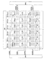
実施形態に係る表示装置の全体の構成図を図1Aに示す。図に示すように、表示領域には画素10がマトリクス状に配置されており、画素10の各列に対応して列方向信号線DTC、各行に対応して第1走査線DSR、2行毎に対応しては第2走査線RSRと基準電位線Vref_rが配置されている。第1走査線DSRは画素の2行毎の行間に2本ずつ配置され上下両側の画素にそれぞれ接続され、第2走査線RSRおよび基準電位線Vref_rは第1走査線DSRが配置されていない行間に配置されて、それぞれが上下の画素に接続されている。 FIG. 1A shows an overall configuration diagram of a display device according to an embodiment. As shown in the figure, the pixels 10 are arranged in a matrix in the display area, the column direction signal line DTC corresponding to each column of the pixels 10, the first scanning line DSR corresponding to each row, and every second row. Corresponding to the second scanning line RSR and the reference potential line Vref_r. Two first scanning lines DSR are arranged between every two rows of pixels and are connected to pixels on both the upper and lower sides, respectively, and the second scanning line RSR and the reference potential line Vref_r are between the rows where the first scanning line DSR is not arranged. Are respectively connected to the upper and lower pixels.
また、画素10の配置される表示領域の外側には、列方向信号線を制御する信号線駆動回路DR、行方向の第1走査線DSRと制御する第1走査線駆動回路SR1と、行方向の第2走査線RSRを制御する第2走査線駆動回路SR2とが設けられている。なお、第2走査線RSRと、基準電位線Vref_rは、その上下2行の画素に共通接続されている。 Further, outside the display area where the pixels 10 are arranged, a signal line driving circuit DR for controlling the column direction signal lines, a first scanning line driving circuit SR1 for controlling the first scanning lines DSR in the row direction, and the row direction And a second scanning line driving circuit SR2 for controlling the second scanning line RSR. Note that the second scanning line RSR and the reference potential line Vref_r are commonly connected to the upper and lower rows of pixels.
また、基準電位線Vref_rは列方向でも構わない。この場合、基準電位線Vref_rは、2列毎に共通であり、左右2列の画素に接続されている。そのときの構成を図1Bに示す。以後、基準電位線Vref_rは行方向にしたときについて説明をする。 Further, the reference potential line Vref_r may be in the column direction. In this case, the reference potential line Vref_r is common to every two columns, and is connected to the pixels on the two right and left columns. The configuration at that time is shown in FIG. 1B. Hereinafter, the case where the reference potential line Vref_r is in the row direction will be described.
図2には、図1Aに示した表示装置に含まれる画素回路の具体的な構成を示す。図においては、第2走査線DSRと基準電位線Vref_rが2行毎に共通であるため2画素分を示す。図2に示すとおり、この画素回路は、OLED(有機EL素子)など電流により発光する発光素子10Eと、サンプリングトランジスタ10Aと、駆動トランジスタ10Cと、スイッチングトランジスタ10Dと、保持容量10Bとを有している。サンプリングトランジスタ10Aのゲ−トには、第1走査線DSRが接続されるとともに、一端が列方向信号線DTC、他端が駆動トランジスタ10Cのゲ−トに接続されている。駆動トランジスタ10Cのドレイン電極は電源VCC、ソ−ス電極は、例えば有機EL素子などの電流駆動型の発光素子10Eのアノ−ドに接続されている。発光素子10Eのカソ−ドは、カソ−ド電源VEEに接続されている。また、駆動トランジスタ10Cのゲ−ト電極とソ−ス電極間に保持容量10Bが接続されている。スイッチングトランジスタ10Dは、一端が駆動トランジスタ10Cのドレインと発光素子10Eのアノ−ドの間に接続され、他端およびゲ−ト電極は、隣接する画素のスイッチングトランジスタ10Dと他端とゲ−ト電極に接続されている。 FIG. 2 shows a specific configuration of a pixel circuit included in the display device shown in FIG. 1A. In the figure, since the second scanning line DSR and the reference potential line Vref_r are common to every two rows, two pixels are shown. As shown in FIG. 2, the pixel circuit includes a light emitting element 10E that emits light by current, such as an OLED (organic EL element), a sampling transistor 10A, a driving transistor 10C, a switching transistor 10D, and a storage capacitor 10B. Yes. A first scanning line DSR is connected to the gate of the sampling transistor 10A, one end is connected to the column direction signal line DTC, and the other end is connected to the gate of the driving transistor 10C. The drain electrode of the driving transistor 10C is connected to the power supply VCC, and the source electrode is connected to the anode of a current driving type light emitting element 10E such as an organic EL element. The cathode of the light emitting element 10E is connected to the cathode power source VEE. A holding capacitor 10B is connected between the gate electrode and the source electrode of the driving transistor 10C. The switching transistor 10D has one end connected between the drain of the driving transistor 10C and the anode of the light emitting element 10E, and the other end and the gate electrode are the switching transistor 10D, the other end, and the gate electrode of the adjacent pixel. It is connected to the.
ここで、図2の上段を画素10、下段の画素11として、下段の画素における各素子については、11A〜11Eの符号を付けている。 Here, assuming that the upper stage of FIG. 2 is the pixel 10 and the lower stage pixel 11, the elements in the lower stage pixels are denoted by reference numerals 11 </ b> A to 11 </ b> E.
なお、図2においては、第1走査線DSRを画素の各行間に1本ずつ配置されるように記載しており、行間に配置される配線の数が1,3,・・・となっているが、画素の配置上は、上述の図1A,Bのように、第1走査線DSRを画素の1行おきに2本ずつ配置するとよい。 In FIG. 2, the first scanning line DSR is described as being arranged one by one between each row of pixels, and the number of wirings arranged between the rows is 1, 3,. However, in terms of pixel arrangement, two first scanning lines DSR may be arranged every other row of pixels as shown in FIGS. 1A and 1B.
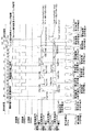
図3にタイミングチャ−トを示す。図4A〜図4Kに各工程の動作を示す。 FIG. 3 shows a timing chart. 4A to 4K show the operation of each process.
図4A:発光期間であり、サンプリングトランジスタ10A、スイッチングトランジスタ10Dはオフされており、発光素子10E、11Eは駆動トランジスタ10C、11Cから供給される電流によって発光状態にある。 FIG. 4A: Light emission period, the sampling transistor 10A and the switching transistor 10D are turned off, and the light emitting elements 10E and 11E are in a light emitting state by the current supplied from the driving transistors 10C and 11C.
図4B:閾値検出準備期間であり、信号線DTCmを基準電位Vrefとして、第1走査線DSRをHレベルとしてサンプリングトランジスタ10Aを導通させる。これによって、駆動トランジスタ10Cのゲ−ト電極の電圧がVrefになる。一方、第2走査線RSRをHレベルとしてスイッチングトランジスタ10Dをオンすることで、駆動トランジスタ10Cのソ−ス電極の電圧がVref_rになる。VrefとVref_rの差電圧を駆動トランジスタ10Cの閾値電圧より大きくするとともに、駆動トランジスタ10Cのソ−ス電極の電圧を発光素子10Eの閾値電圧Vth_10E以下にする。すなわち、Vgs_10C=Vref−Vref_r>Vth_10C、VEE+Vth_10E>Vref_rに設定する。 FIG. 4B: This is a threshold detection preparation period in which the signal line DTCm is set to the reference potential Vref, the first scanning line DSR is set to H level, and the sampling transistor 10A is turned on. As a result, the voltage of the gate electrode of the driving transistor 10C becomes Vref. On the other hand, the voltage of the source electrode of the driving transistor 10C becomes Vref_r by turning on the switching transistor 10D by setting the second scanning line RSR to the H level. With a difference voltage Vref and Vref_r larger than the threshold voltage of the driving transistor 10C, the driving transistor 10C Seo - the voltage of the scan electrode than the threshold voltage Vth_ 10E of the light-emitting element 10E. That, Vgs_ 10C = Vref-Vref_r> Vth_ 10C, is set to VEE + Vth_ 10E> Vref_r.
これによって、駆動トランジスタ10Cはオン状態ではあるが、発光素子10Eに電流は流れない。保持容量10Bには、Vgs−10Cが保持される。 As a result, the drive transistor 10C is in the on state, but no current flows through the light emitting element 10E. The holding capacitor 10B holds Vgs- 10C .
図4C:他の行、ここでは2x(n−4)行目、2x(n−3)行目のサンプリング期間であるため、それ以外の行の画素に影響を及ぼさないようにする必要がある。そのため、サンプリングトランジスタ10A、11Aは非導通としている。 FIG. 4C: Since it is the sampling period of the other row, here the 2x (n-4) th row and the 2x (n-3) th row, it is necessary not to affect the pixels of the other rows. . For this reason, the sampling transistors 10A and 11A are non-conductive.
図4D:閾値検出準備期間であり、信号線DTCmを基準電位Vrefとし、サンプリングトランジスタ10A、11Aを導通させて、駆動トランジスタ10C、11Cのゲ−ト電極をVrefにする。駆動トランジスタ10C、11Cのゲ−ト電極−ソ−ス電極間Vgs_10C、Vgs_11Cの電圧が駆動トランジスタ10C、11Cの閾値電圧Vth_10C、Vth_11Cより大きくする、かつ、発光素子10E、11Eを閾値電圧以下にするために、スイッチングトランジスタ10D、11Dを導通させる。 4D: This is a threshold detection preparation period, the signal line DTCm is set to the reference potential Vref, the sampling transistors 10A and 11A are turned on, and the gate electrodes of the drive transistors 10C and 11C are set to Vref. Driving transistors 10C, 11C of the gate - gate electrode - source - scan electrode between Vgs_ 10C, voltage driving transistor 10C of Vgs_ 11C, 11C of the threshold voltage Vth_ 10C, greater than Vth_ 11C, and the light-emitting element 10E, 11E threshold The switching transistors 10D and 11D are turned on to make the voltage lower.
式で表すと以下となる。
Vgs_10C=Vref−Vref_r>Vth_10C・・・・・・1
Vgs_11C=Vref−Vref_r>Vth_11C・・・・・・2
VEE+Vth_10E>Vref_r・・・・・・3
VEE+Vth_11E>Vref_r ・・・・・・4
This is expressed as follows.
Vgs_ 10C = Vref-Vref_r> Vth_ 10C ······ 1
Vgs_ 11C = Vref-Vref_r> Vth_ 11C ······ 2
VEE + Vth_ 10E> Vref_r ······ 3
VEE + Vth_ 11E> Vref_r ・ ・ ・ ・ ・ ・ 4
ここで、第2走査線は、2ライン毎に共通であるため、(2n,m)番地の画素は、(2n+1,m)番地の画素よりも閾値検出準備期間が1H分長くなる。また、図3では、(2n,m)番地の画素は1Hの期間、(2n+1,m)番地の画素は2Hの期間、閾値検出準備期間としているが、式1〜4の条件を満たすまで繰り返す。保持容量10Bや寄生容量などを十分放電して、上述の関係式が満足できるようにする。 Here, since the second scanning line is common to every two lines, the pixel at the address (2n, m) has a threshold detection preparation period longer by 1H than the pixel at the address (2n + 1, m). In FIG. 3, the pixel at address (2n, m) is a 1H period, the pixel at address (2n + 1, m) is a 2H period, and a threshold detection preparation period. . The storage capacitor 10B and parasitic capacitance are sufficiently discharged so that the above relational expression can be satisfied.
図4E:閾値検出期間であり、信号線DTCmを基準電位Vrefとし、駆動トランジスタ10C、11Cのゲ−ト電極をVrefにするためサンプリングトランジスタ10A、11Aを導通させる。駆動トランジスタ10C、11Cの閾値電圧を検出するため、スイッチングトランジスタ10D、11Dを非導通とする。これによって、駆動トランジスタ10C、11Cがオン状態で、発光素子10E、11Eには電流が流れない状態が維持されており、駆動トランジスタ10C、11Cのゲ−ト電極とソ−ス電極の間の電圧Vgsは、各トランジスタの閾値電圧にセットされるはずである。保持容量10B、11Bには、Vrefと、Vref_rの差電圧が蓄えられており、これが各トランジスタの閾値電圧に向けて変化する。 4E: This is a threshold detection period, and the sampling transistors 10A and 11A are made conductive to set the signal line DTCm to the reference potential Vref and the gate electrodes of the drive transistors 10C and 11C to Vref. In order to detect the threshold voltages of the drive transistors 10C and 11C, the switching transistors 10D and 11D are turned off. As a result, the drive transistors 10C and 11C are in the ON state, and the state where no current flows through the light emitting elements 10E and 11E is maintained, and the voltage between the gate electrode and the source electrode of the drive transistors 10C and 11C is maintained. Vgs should be set to the threshold voltage of each transistor. The storage capacitors 10B and 11B store a difference voltage between Vref and Vref_r, which changes toward the threshold voltage of each transistor.
図4F:図3にはFの工程が5回あるが、それぞれ、2x(n−3)+1行目、2x(n−2)行目、2x(n−2)+1行目、2x(n−1)行目、2x(n−1)+1行目のサンプリング期間であるため、それ以外の行の画素に影響を及ぼさないようにする必要がある。従って、サンプリングトランジスタ10A、11Aは非導通である。この期間では、各電極について前閾値検出期間時の電位が保持される。 FIG. 4F: FIG. 3 shows the process of F five times, but 2x (n−3) +1 line, 2x (n−2) line, 2x (n−2) +1 line, 2x (n Since it is the sampling period of the -1) th row and the 2x (n-1) + 1th row, it is necessary not to affect the pixels in the other rows. Accordingly, the sampling transistors 10A and 11A are non-conductive. In this period, the potential during the previous threshold detection period is held for each electrode.
図4E、図4Fの工程は、駆動トランジスタのゲ−ト電極、ソ−ス電極間電圧Vgsが閾値電圧Vthになるまで繰り返す。図では、5回繰り返している。このとき、駆動トランジスタ10C、11Cのソ−ス電極の電圧Vsはそれぞれ、
Vs_10C=Vref−Vth_10C・・・・・・5
Vs_11C=Vref−Vth_11C・・・・・・6
となる。従って、保持容量10B、11Bには、Vth_10C、Vth_11Cがそれぞれ保持される。
4E and 4F are repeated until the gate electrode-source electrode voltage Vgs of the drive transistor reaches the threshold voltage Vth. In the figure, it is repeated five times. At this time, the voltages Vs of the source electrodes of the drive transistors 10C and 11C are respectively
Vs — 10C = Vref−Vth — 10C ... 5
Vs — 11C = Vref−Vth — 11C ... 6
It becomes. Accordingly, the holding capacitor 10B, the 11B, Vth_ 10C, Vth_ 11C are held respectively.
また、このとき、発光素子10E、11Eに印加されている電圧は閾値電圧Vth_10E、Vth_11E未満である必要がある。すなわち、
VEE+Vth_10E>Vs_10C・・・・・・7
VEE+Vth_11E>Vs_11C・・・・・・8
を満足する必要がある。
At this time, the light-emitting element 10E, the voltage applied to 11E is the threshold voltage Vth_ 10E, needs to be less than Vth_ 11E. That is,
VEE + Vth_ 10E> Vs_ 10C ······ 7
VEE + Vth_ 11E> Vs_ 11C ······ 8
Need to be satisfied.
2n行目について、Vrefは式5と式7より得られる式9を満たす必要があり、Vref_rは、式1を満たす必要がある。
VEE+Vth_10E+Vth_10C>Vref・・・・・・9
For the 2nth row, Vref needs to satisfy Expression 9 obtained from Expression 5 and Expression 7, and Vref_r needs to satisfy Expression 1.
VEE + Vth_ 10E + Vth_ 10C> Vref ······ 9
図4G:信号線を所望の信号電圧Vsig0とし、サンプリングトランジスタ10Aを導通して信号電圧Vsig0のサンプリングを行う。駆動トランジスタ10Cのゲ−ト電極電位は、VrefからVsig0となる。 FIG. 4G: The signal line is set to a desired signal voltage Vsig0, the sampling transistor 10A is turned on, and the signal voltage Vsig0 is sampled. The gate electrode potential of the drive transistor 10C is changed from Vref to Vsig0.
そのとき、駆動トランジスタ10Cのソ−ス電極は、
Vs_10C=Vref−Vth_10C+(Vsig0−Vref)xCap_10E/(Cap_10B+Cap_10E)+VEExCap_10B/(Cap_10B+Cap_10E)
={Cap_10Bx(VEE+Vref)+Cap_10ExVsig0}/(Cap_10B+Cap_10E)−Vth_10C
となり、ゲ−ト電極−ソ−ス電極間の電圧は、
Vgs_10C=Cap_10B/(Cap_10B+Cap_10E)(Vsig0−VEE−Vref)+Vth_10C
となる。
At that time, the source electrode of the driving transistor 10C is
Vs_ 10C = Vref-Vth_ 10C + (Vsig0-Vref) xCap_ 10E / (Cap_ 10B + Cap_ 10E) + VEExCap_ 10B / (Cap_ 10B + Cap_ 10E)
= {Cap_ 10B x (VEE + Vref) + Cap_ 10E xVsig0} / (Cap_ 10B + Cap_ 10E) -Vth_ 10C
The voltage between the gate electrode and the source electrode is
Vgs_ 10C = Cap_ 10B / (Cap_ 10B + Cap_ 10E) (Vsig0-VEE-Vref) + Vth_ 10C
It becomes.
図4H:サンプリングトランジスタ10A、11Aは非導通であるため、各電極について前工程の電位が保持される。 FIG. 4H: Since the sampling transistors 10A and 11A are non-conductive, the potential of the previous process is held for each electrode.
図4J:2n+1行目の最後の閾値検出期間であり、サンプリングトランジスタ10Aは非導通、11Aは導通としている。 FIG. 4J: This is the last threshold detection period in the (2n + 1) th row, where the sampling transistor 10A is non-conductive and 11A is conductive.
図4K:信号線を所望の信号電圧Vsig1とし、サンプリングトランジスタ11Aにて信号電圧Vsig1のサンプリングを行う。駆動トランジスタ11Cのゲ−ト電極電位は、VrefからVsig1となる。 FIG. 4K: The signal line is set to a desired signal voltage Vsig1, and the sampling of the signal voltage Vsig1 is performed by the sampling transistor 11A. The gate electrode potential of the drive transistor 11C changes from Vref to Vsig1.
そのとき、駆動トランジスタ11Cのソ−ス電極は、
Vs_11C=Vref−Vth_11C+(Vsig0−Vref)xCap_11E/(Cap_11B+Cap_11E)+VEExCap_11B/(Cap_11B+Cap_11E)
となり、ゲ−ト電極−ソ−ス電極間の電圧は、
Vgs_11C=Cap_11B/(Cap_11B+Cap_11E)x(Vsig0−VEE−Vref)+Vth_11C
となる。
At that time, the source electrode of the drive transistor 11C is
Vs_ 11C = Vref-Vth_ 11C + (Vsig0-Vref) xCap_ 11E / (Cap_ 11B + Cap_ 11E) + VEExCap_ 11B / (Cap_ 11B + Cap_ 11E)
The voltage between the gate electrode and the source electrode is
Vgs_ 11C = Cap_ 11B / (Cap_ 11B + Cap_ 11E) x (Vsig0-VEE-Vref) + Vth_ 11C
It becomes.
駆動トランジスタのIdsの特性式は、Ids=β/2(Vgs−Vth)2で表される。それぞれ、Vgs_10C、Vgs_11Cをそれぞれ代入すると、
Ids0=β/2{Cap_10B/(Cap_10B+Cap_10E)x(Vsig0−VEE−Vref)}2
Ids1=β/2{Cap_11B/(Cap_11B+Cap_11E)x(Vsig1−VEE−Vref)}2
となり、Vthの項は補正され、駆動電流のばらつきを抑えることができる。
The characteristic equation of Ids of the driving transistor is expressed by Ids = β / 2 (Vgs−Vth) 2 . Each, Vgs_ 10C, and if the values are the Vgs_ 11C,
Ids0 = β / 2 {Cap_ 10B / (Cap_ 10B + Cap_ 10E) x (Vsig0-VEE-Vref)} 2
Ids1 = β / 2 {Cap_ 11B / (Cap_ 11B + Cap_ 11E) x (Vsig1-VEE-Vref)} 2
Thus, the term of Vth is corrected, and variations in drive current can be suppressed.
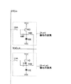
図5Aに発光素子形成前に信号電圧をサンプリングするトランジスタ、駆動トランジスタ、スイッチングトランジスタの不具合を確認するときの全体図を示す。基準電位線Vref_rは表示領域の外で、所定数まとめて接続するが、電流測定装置数、測定時間、S/N比を勘案し、束ねる基準電位線Vref_rの数を決定する。図ではVref_r_0とVref_r_nをひとつに束ねている。そして、この基準電位線Vref_rをまとめた端部に測定用のプローブポイントを作成してある。 FIG. 5A shows an overall view when a failure of a transistor, a driving transistor, and a switching transistor for sampling a signal voltage before forming a light emitting element is confirmed. A predetermined number of reference potential lines Vref_r are connected together outside the display area, but the number of reference potential lines Vref_r to be bundled is determined in consideration of the number of current measurement devices, measurement time, and S / N ratio. In the figure, Vref_r_0 and Vref_r_n are bundled together. And the probe point for a measurement is created in the end part which put together this reference potential line Vref_r.
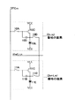
図5Bに発光素子形成前に信号電圧をサンプリングするサンプリングトランジスタ10A、駆動トランジスタ10C、スイッチングトランジスタ10Dの不具合を確認するときの発光素子10Eの形成前の画素回路を示す。すなわち、発光素子10Eが形成された場合、駆動トランジスタ10Cのソースが発光素子10Eのアノードに接続されるが、発光素子10Eの形成前はこの接続がない。 FIG. 5B shows a pixel circuit before the formation of the light emitting element 10E when confirming defects of the sampling transistor 10A, the driving transistor 10C, and the switching transistor 10D that sample the signal voltage before the light emitting element is formed. That is, when the light emitting element 10E is formed, the source of the driving transistor 10C is connected to the anode of the light emitting element 10E, but this connection is not made before the light emitting element 10E is formed.
サンプリングトランジスタ10A、スイッチングトランジスタ10Dを導通状態とし、信号線DTCmより、信号電位を駆動トランジスタ10Cのゲ−ト電極に与え、そのときに、駆動トランジスタ10Cのドレイン電極−ソ−ス電極間に流れる電流をVref_rに接続されたプローブポイントにおいて測定することで不具合を確認する。すなわち、第2走査線RSRをHレベルとして、第1走査線DSRを順次Hレベルにする。これによって、対応する画素のサンプリングトランジスタ10Aがオンし、信号線DTCの電位が画素に取り込まれ、その電流に応じた電流が流れ、プローブポイントから外部のアースに流れる電流を測定器で測定することで画素回路の動作を確認できる。 The sampling transistor 10A and the switching transistor 10D are turned on, and a signal potential is applied from the signal line DTCm to the gate electrode of the driving transistor 10C. At this time, a current flows between the drain electrode and the source electrode of the driving transistor 10C. Is confirmed at the probe point connected to Vref_r. That is, the second scanning line RSR is set to H level, and the first scanning line DSR is sequentially set to H level. As a result, the sampling transistor 10A of the corresponding pixel is turned on, the potential of the signal line DTC is taken into the pixel, a current corresponding to the current flows, and the current flowing from the probe point to the external ground is measured by the measuring instrument. Can confirm the operation of the pixel circuit.
特に、1つの画素回路における駆動トランジスタ10Cの閾値電圧を含む、IV特性など検出することができる。 In particular, IV characteristics including the threshold voltage of the driving transistor 10C in one pixel circuit can be detected.
なお、信号線DTCを1つずつオンすることで、1画素ずつ検査が行えるが、ある程度まとめて検査しても、素子に不具合があるか否かの検出は行える。 Note that by turning on the signal line DTC one by one, the inspection can be performed for each pixel, but even if the inspection is performed to some extent, it is possible to detect whether or not there is a defect in the element.
上述の実施形態では、nチャネルトランジスタを用いたが、pチャネルトランジスタを用いることもできる。駆動トランジスタ10Cにpチャネルトランジスタを用いた場合、電源VCC側にソース電極が配置され、発光素子10E、保持容量10Bも電源VCC側に配置される。 In the above embodiment, an n-channel transistor is used, but a p-channel transistor can also be used. When a p-channel transistor is used as the drive transistor 10C, the source electrode is disposed on the power supply VCC side, and the light emitting element 10E and the storage capacitor 10B are also disposed on the power supply VCC side.
本実施形態の表示装置によれば、各画素回路において、駆動用トランジスタへ電流が流れ始める閾値電圧の補正を行い、駆動電流のばらつきを抑えることができる。また、発光素子形成前に画素の検査、すなわち、サンプリングトランジスタ、駆動トランジスタ、スイッチングトランジスタの不具合を発光素子形成前に確認することができるため、次工程に不良品を送らないことで、コストの低減化を実現することができる。 According to the display device of this embodiment, in each pixel circuit, it is possible to correct the threshold voltage at which current starts to flow to the driving transistor, and to suppress variation in driving current. In addition, pixel inspection prior to light-emitting element formation, that is, defects in the sampling transistor, drive transistor, and switching transistor can be confirmed before light-emitting element formation, reducing costs by not sending defective products to the next process. Can be realized.
10,11 画素、10A,11A サンプリングトランジスタ、10B,11B 保持容量、10C,11C 駆動トランジスタ、10D,11D スイッチングトランジスタ、10E,11E 発光素子。 10, 11 pixels, 10A, 11A Sampling transistor, 10B, 11B Retention capacitance, 10C, 11C Drive transistor, 10D, 11D Switching transistor, 10E, 11E Light emitting element.
Claims (8)
このサンプリングトランジスタの他端にゲートが接続され、ドレインが第1電源に接続される駆動トランジスタと、
この駆動トランジスタのソースと第2電源との間に接続され、前記駆動トランジスタに流れる電流によって駆動される発光素子と、
前記駆動トランジスタのゲート・ソース間に接続される保持容量と、
前記駆動トランジスタのソースと基準電位線の間に配置され、第2走査線によってオンオフされるスイッチングトランジスタと、
を含み、
前記信号線に基準信号電圧が設定されている期間に、前記サンプリングトランジスタと前記スイッチングトランジスタを導通させ、前記駆動トランジスタのゲート・ソース間電圧を前記駆動トランジスタの閾値電圧以上とした状態で前記保持容量に基準信号電圧と基準電位の差電圧を充電すると共に、前記駆動トランジスタのソースの電圧を基準電位に設定することで前記発光素子への印加電圧をその閾値電圧以下とし、
その後、前記信号線に基準信号電圧が設定されている期間に、前記サンプリングトランジスタと前記スイッチングトランジスタを導通させるとともに、前記スイッチングトランジスタをオフにすることで、前記発光素子への印加電圧をその閾値電圧以下に維持したまま、前記保持容量に前記駆動トランジスタの閾値電圧に相当する電圧を保持し、
前記信号線に表示信号電圧が設定されている期間に、前記サンプリングトランジスタを導通させ前記信号電圧をサンプリングし、前記保持容量の保持していた閾値電圧に前記信号電圧を重畳する、
画素回路。 A sampling transistor having one end connected to the signal line and turned on and off by the first scanning line;
A driving transistor having a gate connected to the other end of the sampling transistor and a drain connected to the first power supply;
A light emitting element connected between a source of the driving transistor and a second power source and driven by a current flowing through the driving transistor;
A storage capacitor connected between the gate and source of the drive transistor;
A switching transistor disposed between a source of the driving transistor and a reference potential line and turned on and off by a second scanning line;
Including
In a period in which a reference signal voltage is set on the signal line, the sampling transistor and the switching transistor are made conductive, and the storage capacitor is set in a state where the gate-source voltage of the driving transistor is equal to or higher than the threshold voltage of the driving transistor. And charging the difference voltage between the reference signal voltage and the reference potential, and setting the voltage of the source of the driving transistor to the reference potential, thereby making the voltage applied to the light emitting element equal to or lower than the threshold voltage,
Thereafter, during a period in which a reference signal voltage is set on the signal line, the sampling transistor and the switching transistor are made conductive, and the switching transistor is turned off, whereby the applied voltage to the light emitting element is set to the threshold voltage. The voltage corresponding to the threshold voltage of the drive transistor is held in the storage capacitor while maintaining the following:
In a period in which a display signal voltage is set on the signal line, the sampling transistor is made conductive to sample the signal voltage, and the signal voltage is superimposed on the threshold voltage held by the storage capacitor,
Pixel circuit.
複数の信号線と、
この複数の信号線を駆動する信号線駆動回路と、
複数の第1走査線と、
この第1走査線を駆動する第1走査線駆動回路と、
複数の第2走査線と、
この第2走査線を駆動する第2走査線駆動回路と、
基準電位が供給される基準電位線と、
を含み、
各画素は、
一端が信号線に接続され、第1走査線によってオンオフされるサンプリングトランジスタと、
このサンプリングトランジスタの他端にゲートが接続され、ドレインが第1電源に接続される駆動トランジスタと、
この駆動トランジスタのソースと第2電源との間に接続され、前記駆動トランジスタに流れる電流によって駆動される発光素子と、
前記駆動トランジスタのゲート・ソース間に接続される保持容量と、
前記駆動トランジスタのソースと基準電位線の間に配置され、第2走査線によってオンオフされるスイッチングトランジスタと、
を含み、
前記信号線に基準信号電圧が設定されている期間に、前記サンプリングトランジスタと前記スイッチングトランジスタを導通させ、前記駆動トランジスタのゲート・ソース間電圧を前記駆動トランジスタの閾値電圧以上とした状態で前記保持容量に基準信号電圧と基準電位の差電圧を充電すると共に、前記駆動トランジスタのソースの電圧を基準電位に設定することで前記発光素子への印加電圧をその閾値電圧以下とし、
その後、前記信号線に基準信号電圧が設定されている期間に、前記サンプリングトランジスタと前記スイッチングトランジスタを導通させるとともに、前記スイッチングトランジスタをオフにすることで、前記発光素子への印加電圧をその閾値電圧以下に維持したまま、前記保持容量に前記駆動トランジスタの閾値電圧に相当する電圧を保持し、
前記信号線に表示信号電圧が設定されている期間に、前記サンプリングトランジスタを導通させ前記信号電圧をサンプリングし、前記保持容量の保持していた閾値電圧に前記信号電圧を重畳する、
表示装置。 A display device in which a plurality of pixels are arranged in a matrix,
Multiple signal lines,
A signal line driving circuit for driving the plurality of signal lines;
A plurality of first scan lines;
A first scanning line driving circuit for driving the first scanning line;
A plurality of second scan lines;
A second scanning line driving circuit for driving the second scanning line;
A reference potential line to which a reference potential is supplied;
Including
Each pixel is
A sampling transistor having one end connected to the signal line and turned on and off by the first scanning line;
A driving transistor having a gate connected to the other end of the sampling transistor and a drain connected to the first power supply;
A light emitting element connected between a source of the driving transistor and a second power source and driven by a current flowing through the driving transistor;
A storage capacitor connected between the gate and source of the drive transistor;
A switching transistor disposed between a source of the driving transistor and a reference potential line and turned on and off by a second scanning line;
Including
In a period in which a reference signal voltage is set on the signal line, the sampling transistor and the switching transistor are made conductive, and the storage capacitor is set in a state where the gate-source voltage of the driving transistor is equal to or higher than the threshold voltage of the driving transistor. And charging the difference voltage between the reference signal voltage and the reference potential, and setting the voltage of the source of the driving transistor to the reference potential, thereby making the voltage applied to the light emitting element equal to or lower than the threshold voltage,
Thereafter, during a period in which a reference signal voltage is set on the signal line, the sampling transistor and the switching transistor are made conductive, and the switching transistor is turned off, whereby the applied voltage to the light emitting element is set to the threshold voltage. The voltage corresponding to the threshold voltage of the drive transistor is held in the storage capacitor while maintaining the following:
In a period in which a display signal voltage is set on the signal line, the sampling transistor is made conductive to sample the signal voltage, and the signal voltage is superimposed on the threshold voltage held by the storage capacitor,
Display device.
前記基準電位線は、2行の画素に共通であって画素の2行毎に行方向に配置されている表示装置。 The display device according to claim 2,
The reference potential line is common to two rows of pixels, and is arranged in the row direction every two rows of pixels.
前記基準電位線は、2列の画素に共通であって画素の2列毎に列方向に配置されている表示装置。 The display device according to claim 2,
The reference potential line is common to two columns of pixels and is arranged in the column direction for every two columns of pixels.
前記画素が配列される表示領域の外部において、前記基準電位線をまとめて接続している表示装置。 A display device according to any one of claims 2 to 4,
A display device in which the reference potential lines are connected together outside a display region in which the pixels are arranged.
前記基準電位線に接続されるプローブポイントであって、少なくとも前記発光素子の形成前に、プローブにより外部からポイント可能プローブポイントを有する表示装置。 The display device according to claim 5,
A display device having probe points connected to the reference potential line, the probe points being capable of being pointed from the outside by a probe at least before the light emitting element is formed.
前記第2走査線は、2行の画素に共通であって画素の2行毎に行方向に配置されている表示装置。 The display device according to claim 2, wherein
The second scanning line is common to two rows of pixels, and is arranged in the row direction every two rows of pixels.
前記発光素子の形成前において、基準電位線にプローブを接続し、各画素における前記サンプリングトランジスタ、スイッチングトランジスタのオンオフを制御して、基準電位線から流れ出る電流を検出することで、駆動トランジスタの電流−電圧特性を測定する表示装置の検査方法。 An inspection method for the display device according to claim 2,
Before forming the light emitting element, a probe is connected to a reference potential line, and the sampling transistor and the switching transistor in each pixel are controlled on and off to detect the current flowing out from the reference potential line. A display device inspection method for measuring voltage characteristics.
Priority Applications (8)
| Application Number | Priority Date | Filing Date | Title |
|---|---|---|---|
| JP2009257527A JP5503255B2 (en) | 2009-11-10 | 2009-11-10 | Pixel circuit, display device, and inspection method |
| EP10830537A EP2499632A4 (en) | 2009-11-10 | 2010-11-04 | Pixel circuit, display device, and inspection method |
| PCT/US2010/055368 WO2011059867A1 (en) | 2009-11-10 | 2010-11-04 | Pixel circuit, display device, and inspection method |
| US13/508,713 US8754882B2 (en) | 2009-11-10 | 2010-11-04 | Pixel circuit, display device, and inspection method |
| KR1020127013445A KR20120105453A (en) | 2009-11-10 | 2010-11-04 | Pixel circuit, display device, and inspection method |
| CN2010800507459A CN102598097A (en) | 2009-11-10 | 2010-11-04 | Pixel circuit, display device, and inspection method |
| TW099138105A TW201128610A (en) | 2009-11-10 | 2010-11-05 | Pixel circuit, display device, and inspection method |
| US14/276,392 US9569991B2 (en) | 2009-11-10 | 2014-05-13 | Pixel circuit, display device, and inspection method |
Applications Claiming Priority (1)
| Application Number | Priority Date | Filing Date | Title |
|---|---|---|---|
| JP2009257527A JP5503255B2 (en) | 2009-11-10 | 2009-11-10 | Pixel circuit, display device, and inspection method |
Publications (2)
| Publication Number | Publication Date |
|---|---|
| JP2011102879A true JP2011102879A (en) | 2011-05-26 |
| JP5503255B2 JP5503255B2 (en) | 2014-05-28 |
Family
ID=43991963
Family Applications (1)
| Application Number | Title | Priority Date | Filing Date |
|---|---|---|---|
| JP2009257527A Active JP5503255B2 (en) | 2009-11-10 | 2009-11-10 | Pixel circuit, display device, and inspection method |
Country Status (7)
| Country | Link |
|---|---|
| US (2) | US8754882B2 (en) |
| EP (1) | EP2499632A4 (en) |
| JP (1) | JP5503255B2 (en) |
| KR (1) | KR20120105453A (en) |
| CN (1) | CN102598097A (en) |
| TW (1) | TW201128610A (en) |
| WO (1) | WO2011059867A1 (en) |
Cited By (2)
| Publication number | Priority date | Publication date | Assignee | Title |
|---|---|---|---|---|
| KR20140117742A (en) * | 2013-03-26 | 2014-10-08 | 엘지디스플레이 주식회사 | Organic light-emitting display device and Apparatus for compensating the same |
| KR20150064787A (en) * | 2013-12-03 | 2015-06-12 | 엘지디스플레이 주식회사 | Organic lighting emitting device and method for compensating degradation thereof |
Families Citing this family (15)
| Publication number | Priority date | Publication date | Assignee | Title |
|---|---|---|---|---|
| CN104112432B (en) * | 2013-04-17 | 2016-10-26 | 瀚宇彩晶股份有限公司 | Display |
| JP6164059B2 (en) | 2013-11-15 | 2017-07-19 | ソニー株式会社 | Display device, electronic apparatus, and display device driving method |
| US9495910B2 (en) * | 2013-11-22 | 2016-11-15 | Global Oled Technology Llc | Pixel circuit, driving method, display device, and inspection method |
| KR102196908B1 (en) * | 2014-07-18 | 2020-12-31 | 삼성디스플레이 주식회사 | Organic light emitting display device and driving method thereof |
| KR102177216B1 (en) * | 2014-10-10 | 2020-11-11 | 삼성디스플레이 주식회사 | Display apparatus and display apparatus controlling method |
| KR102230928B1 (en) * | 2014-10-13 | 2021-03-24 | 삼성디스플레이 주식회사 | Orgainic light emitting display and driving method for the same |
| CN104464586B (en) * | 2014-12-30 | 2017-02-22 | 京东方科技集团股份有限公司 | Display panel detection device and method |
| CN104658482B (en) * | 2015-03-16 | 2017-05-31 | 深圳市华星光电技术有限公司 | AMOLED pixel-driving circuits and image element driving method |
| JP6804255B2 (en) * | 2015-12-15 | 2020-12-23 | 三星エスディアイ株式会社Samsung SDI Co., Ltd. | Electrode forming composition and electrodes and solar cells manufactured using the composition |
| KR102526484B1 (en) * | 2015-12-30 | 2023-04-26 | 엘지디스플레이 주식회사 | Organic Light Emitting Diode Display Device and Driving Method of the same |
| KR102366285B1 (en) * | 2015-12-31 | 2022-02-23 | 엘지디스플레이 주식회사 | Organic light emitting display device and method for driving the same |
| CN108091301B (en) | 2017-12-14 | 2020-06-09 | 京东方科技集团股份有限公司 | Voltage sampling circuit and method and display device |
| KR20200122456A (en) * | 2019-04-17 | 2020-10-28 | 삼성디스플레이 주식회사 | Display device including a plurality of data drivers |
| CN111044874B (en) * | 2019-12-31 | 2022-05-24 | 武汉天马微电子有限公司 | Display module, detection method and electronic equipment |
| KR102164276B1 (en) * | 2020-02-27 | 2020-10-12 | 엘지디스플레이 주식회사 | Organic electro luminescent display device, and display panel and driving method thereof |
Citations (7)
| Publication number | Priority date | Publication date | Assignee | Title |
|---|---|---|---|---|
| JP2004191603A (en) * | 2002-12-10 | 2004-07-08 | Semiconductor Energy Lab Co Ltd | Display device, and method for inspecting the same |
| JP2004334204A (en) * | 2003-04-30 | 2004-11-25 | Eastman Kodak Co | Four-color organic light-emitting device |
| JP2005285631A (en) * | 2004-03-30 | 2005-10-13 | Casio Comput Co Ltd | Pixel circuit board, test method of pixel circuit board, transistor group, test method and test device of transistor group |
| JP2006139079A (en) * | 2004-11-12 | 2006-06-01 | Eastman Kodak Co | Substrate for light emitting panel, test method for the same and light emitting panel |
| JP2008052111A (en) * | 2006-08-25 | 2008-03-06 | Mitsubishi Electric Corp | Tft array substrate, inspection method for same, and display device |
| JP2009157019A (en) * | 2007-12-26 | 2009-07-16 | Sony Corp | Display device and electronic equipment |
| WO2009087746A1 (en) * | 2008-01-07 | 2009-07-16 | Panasonic Corporation | Display device, electronic device and driving method |
Family Cites Families (19)
| Publication number | Priority date | Publication date | Assignee | Title |
|---|---|---|---|---|
| DE3235119A1 (en) * | 1982-09-22 | 1984-03-22 | Siemens AG, 1000 Berlin und 8000 München | ARRANGEMENT FOR THE TESTING OF MICROWIRE WIRES AND METHOD FOR THEIR OPERATION |
| JP3800404B2 (en) * | 2001-12-19 | 2006-07-26 | 株式会社日立製作所 | Image display device |
| JP3613253B2 (en) | 2002-03-14 | 2005-01-26 | 日本電気株式会社 | Current control element drive circuit and image display device |
| GB0218170D0 (en) | 2002-08-06 | 2002-09-11 | Koninkl Philips Electronics Nv | Electroluminescent display devices |
| JP4409821B2 (en) * | 2002-11-21 | 2010-02-03 | 奇美電子股▲ふん▼有限公司 | EL display device |
| US7265572B2 (en) * | 2002-12-06 | 2007-09-04 | Semicondcutor Energy Laboratory Co., Ltd. | Image display device and method of testing the same |
| GB0307475D0 (en) | 2003-04-01 | 2003-05-07 | Koninkl Philips Electronics Nv | Active matrix display devices |
| US7173590B2 (en) | 2004-06-02 | 2007-02-06 | Sony Corporation | Pixel circuit, active matrix apparatus and display apparatus |
| CA2472671A1 (en) * | 2004-06-29 | 2005-12-29 | Ignis Innovation Inc. | Voltage-programming scheme for current-driven amoled displays |
| US7071717B2 (en) * | 2004-10-28 | 2006-07-04 | Agilent Technologies, Inc. | Universal test fixture |
| US7317434B2 (en) * | 2004-12-03 | 2008-01-08 | Dupont Displays, Inc. | Circuits including switches for electronic devices and methods of using the electronic devices |
| US20090303260A1 (en) * | 2005-11-29 | 2009-12-10 | Shinji Takasugi | Image Display Device |
| FR2900492B1 (en) * | 2006-04-28 | 2008-10-31 | Thales Sa | ORGANIC ELECTROLUMINESCENT SCREEN |
| KR101245218B1 (en) * | 2006-06-22 | 2013-03-19 | 엘지디스플레이 주식회사 | Organic light emitting diode display |
| KR101031694B1 (en) | 2007-03-29 | 2011-04-29 | 도시바 모바일 디스플레이 가부시키가이샤 | El display device |
| KR101361981B1 (en) * | 2008-02-19 | 2014-02-21 | 엘지디스플레이 주식회사 | Organic Light Emitting Diode Display And Driving Method Thereof |
| JP4737221B2 (en) * | 2008-04-16 | 2011-07-27 | ソニー株式会社 | Display device |
| US7863123B2 (en) * | 2009-01-19 | 2011-01-04 | International Business Machines Corporation | Direct contact between high-κ/metal gate and wiring process flow |
| TWI417840B (en) * | 2009-08-26 | 2013-12-01 | Au Optronics Corp | Pixel circuit, active matrix organic light emitting diode (oled) display and driving method for pixel circuit |
-
2009
- 2009-11-10 JP JP2009257527A patent/JP5503255B2/en active Active
-
2010
- 2010-11-04 US US13/508,713 patent/US8754882B2/en active Active
- 2010-11-04 WO PCT/US2010/055368 patent/WO2011059867A1/en active Application Filing
- 2010-11-04 KR KR1020127013445A patent/KR20120105453A/en not_active Application Discontinuation
- 2010-11-04 CN CN2010800507459A patent/CN102598097A/en active Pending
- 2010-11-04 EP EP10830537A patent/EP2499632A4/en not_active Withdrawn
- 2010-11-05 TW TW099138105A patent/TW201128610A/en unknown
-
2014
- 2014-05-13 US US14/276,392 patent/US9569991B2/en active Active
Patent Citations (7)
| Publication number | Priority date | Publication date | Assignee | Title |
|---|---|---|---|---|
| JP2004191603A (en) * | 2002-12-10 | 2004-07-08 | Semiconductor Energy Lab Co Ltd | Display device, and method for inspecting the same |
| JP2004334204A (en) * | 2003-04-30 | 2004-11-25 | Eastman Kodak Co | Four-color organic light-emitting device |
| JP2005285631A (en) * | 2004-03-30 | 2005-10-13 | Casio Comput Co Ltd | Pixel circuit board, test method of pixel circuit board, transistor group, test method and test device of transistor group |
| JP2006139079A (en) * | 2004-11-12 | 2006-06-01 | Eastman Kodak Co | Substrate for light emitting panel, test method for the same and light emitting panel |
| JP2008052111A (en) * | 2006-08-25 | 2008-03-06 | Mitsubishi Electric Corp | Tft array substrate, inspection method for same, and display device |
| JP2009157019A (en) * | 2007-12-26 | 2009-07-16 | Sony Corp | Display device and electronic equipment |
| WO2009087746A1 (en) * | 2008-01-07 | 2009-07-16 | Panasonic Corporation | Display device, electronic device and driving method |
Cited By (4)
| Publication number | Priority date | Publication date | Assignee | Title |
|---|---|---|---|---|
| KR20140117742A (en) * | 2013-03-26 | 2014-10-08 | 엘지디스플레이 주식회사 | Organic light-emitting display device and Apparatus for compensating the same |
| KR102017673B1 (en) * | 2013-03-26 | 2019-09-04 | 엘지디스플레이 주식회사 | Organic light-emitting display device and Apparatus for compensating the same |
| KR20150064787A (en) * | 2013-12-03 | 2015-06-12 | 엘지디스플레이 주식회사 | Organic lighting emitting device and method for compensating degradation thereof |
| KR102067228B1 (en) * | 2013-12-03 | 2020-01-17 | 엘지디스플레이 주식회사 | Organic lighting emitting device and method for compensating degradation thereof |
Also Published As
| Publication number | Publication date |
|---|---|
| US20130016083A1 (en) | 2013-01-17 |
| WO2011059867A1 (en) | 2011-05-19 |
| WO2011059867A8 (en) | 2013-06-06 |
| KR20120105453A (en) | 2012-09-25 |
| EP2499632A1 (en) | 2012-09-19 |
| CN102598097A (en) | 2012-07-18 |
| EP2499632A4 (en) | 2013-04-03 |
| US20140239961A1 (en) | 2014-08-28 |
| US9569991B2 (en) | 2017-02-14 |
| JP5503255B2 (en) | 2014-05-28 |
| US8754882B2 (en) | 2014-06-17 |
| TW201128610A (en) | 2011-08-16 |
Similar Documents
| Publication | Publication Date | Title |
|---|---|---|
| JP5503255B2 (en) | Pixel circuit, display device, and inspection method | |
| US9805642B2 (en) | Method of driving an organic light emitting display device which prevents discernment of a sensing line | |
| JP4203772B2 (en) | Display device and driving method thereof | |
| JP5308796B2 (en) | Display device and pixel circuit | |
| JP4203773B2 (en) | Display device | |
| JP4984715B2 (en) | Display device driving method and display element driving method | |
| EP3242287B1 (en) | Pixel circuit and drive method therefor, and active matrix organic light-emitting display | |
| US10783827B2 (en) | Display device and driving method thereof | |
| JP2008122632A (en) | Display device | |
| JP2007310311A (en) | Display device and its driving method | |
| US20070195019A1 (en) | Image display apparatus | |
| KR20140135618A (en) | Electro-optical device and driving method thereof | |
| US20210312856A1 (en) | Pixel circuit and display panel | |
| JP2008122633A (en) | Display device | |
| JP2008139520A (en) | Display device | |
| US8339335B2 (en) | Electroluminescence display apparatus and method of correcting display variation for electroluminescence display apparatus | |
| CN209785530U (en) | Pixel compensation circuit | |
| JP5359073B2 (en) | Display device | |
| JP2008310075A (en) | Image display device | |
| KR20150141451A (en) | Organic Light Emitting Diode And Method Of Fabricating The Same | |
| JP2013105159A (en) | Matrix substrate and inspection method of matrix substrate | |
| JP4544355B2 (en) | Pixel circuit, driving method thereof, display device, and driving method thereof | |
| JP2008250003A (en) | Display device | |
| KR20140055535A (en) | Organic light-emitting diode display device |
Legal Events
| Date | Code | Title | Description |
|---|---|---|---|
| A621 | Written request for application examination |
Free format text: JAPANESE INTERMEDIATE CODE: A621 Effective date: 20120611 |
|
| A977 | Report on retrieval |
Free format text: JAPANESE INTERMEDIATE CODE: A971007 Effective date: 20130115 |
|
| A131 | Notification of reasons for refusal |
Free format text: JAPANESE INTERMEDIATE CODE: A131 Effective date: 20130219 |
|
| A521 | Request for written amendment filed |
Free format text: JAPANESE INTERMEDIATE CODE: A523 Effective date: 20130507 |
|
| A521 | Request for written amendment filed |
Free format text: JAPANESE INTERMEDIATE CODE: A523 Effective date: 20130520 |
|
| A131 | Notification of reasons for refusal |
Free format text: JAPANESE INTERMEDIATE CODE: A131 Effective date: 20130806 |
|
| A521 | Request for written amendment filed |
Free format text: JAPANESE INTERMEDIATE CODE: A523 Effective date: 20131001 |
|
| A131 | Notification of reasons for refusal |
Free format text: JAPANESE INTERMEDIATE CODE: A131 Effective date: 20131210 |
|
| A521 | Request for written amendment filed |
Free format text: JAPANESE INTERMEDIATE CODE: A523 Effective date: 20131219 |
|
| TRDD | Decision of grant or rejection written | ||
| A01 | Written decision to grant a patent or to grant a registration (utility model) |
Free format text: JAPANESE INTERMEDIATE CODE: A01 Effective date: 20140311 |
|
| A61 | First payment of annual fees (during grant procedure) |
Free format text: JAPANESE INTERMEDIATE CODE: A61 Effective date: 20140314 |
|
| R150 | Certificate of patent or registration of utility model |
Ref document number: 5503255 Country of ref document: JP Free format text: JAPANESE INTERMEDIATE CODE: R150 |
|
| R250 | Receipt of annual fees |
Free format text: JAPANESE INTERMEDIATE CODE: R250 |
|
| R250 | Receipt of annual fees |
Free format text: JAPANESE INTERMEDIATE CODE: R250 |
|
| R250 | Receipt of annual fees |
Free format text: JAPANESE INTERMEDIATE CODE: R250 |
|
| R250 | Receipt of annual fees |
Free format text: JAPANESE INTERMEDIATE CODE: R250 |
|
| R250 | Receipt of annual fees |
Free format text: JAPANESE INTERMEDIATE CODE: R250 |
|
| R250 | Receipt of annual fees |
Free format text: JAPANESE INTERMEDIATE CODE: R250 |
|
| R250 | Receipt of annual fees |
Free format text: JAPANESE INTERMEDIATE CODE: R250 |
|
| R250 | Receipt of annual fees |
Free format text: JAPANESE INTERMEDIATE CODE: R250 |