JP2011069366A - ガスタービン - Google Patents
ガスタービン Download PDFInfo
- Publication number
- JP2011069366A JP2011069366A JP2010212081A JP2010212081A JP2011069366A JP 2011069366 A JP2011069366 A JP 2011069366A JP 2010212081 A JP2010212081 A JP 2010212081A JP 2010212081 A JP2010212081 A JP 2010212081A JP 2011069366 A JP2011069366 A JP 2011069366A
- Authority
- JP
- Japan
- Prior art keywords
- gas turbine
- passage
- guide vane
- gap
- rotor
- Prior art date
- Legal status (The legal status is an assumption and is not a legal conclusion. Google has not performed a legal analysis and makes no representation as to the accuracy of the status listed.)
- Granted
Links
Images

Classifications
-
- F—MECHANICAL ENGINEERING; LIGHTING; HEATING; WEAPONS; BLASTING
- F01—MACHINES OR ENGINES IN GENERAL; ENGINE PLANTS IN GENERAL; STEAM ENGINES
- F01D—NON-POSITIVE DISPLACEMENT MACHINES OR ENGINES, e.g. STEAM TURBINES
- F01D9/00—Stators
- F01D9/02—Nozzles; Nozzle boxes; Stator blades; Guide conduits, e.g. individual nozzles
- F01D9/04—Nozzles; Nozzle boxes; Stator blades; Guide conduits, e.g. individual nozzles forming ring or sector
-
- F—MECHANICAL ENGINEERING; LIGHTING; HEATING; WEAPONS; BLASTING
- F01—MACHINES OR ENGINES IN GENERAL; ENGINE PLANTS IN GENERAL; STEAM ENGINES
- F01D—NON-POSITIVE DISPLACEMENT MACHINES OR ENGINES, e.g. STEAM TURBINES
- F01D11/00—Preventing or minimising internal leakage of working-fluid, e.g. between stages
- F01D11/005—Sealing means between non relatively rotating elements
-
- F—MECHANICAL ENGINEERING; LIGHTING; HEATING; WEAPONS; BLASTING
- F01—MACHINES OR ENGINES IN GENERAL; ENGINE PLANTS IN GENERAL; STEAM ENGINES
- F01D—NON-POSITIVE DISPLACEMENT MACHINES OR ENGINES, e.g. STEAM TURBINES
- F01D25/00—Component parts, details, or accessories, not provided for in, or of interest apart from, other groups
- F01D25/08—Cooling; Heating; Heat-insulation
- F01D25/12—Cooling
-
- F—MECHANICAL ENGINEERING; LIGHTING; HEATING; WEAPONS; BLASTING
- F01—MACHINES OR ENGINES IN GENERAL; ENGINE PLANTS IN GENERAL; STEAM ENGINES
- F01D—NON-POSITIVE DISPLACEMENT MACHINES OR ENGINES, e.g. STEAM TURBINES
- F01D5/00—Blades; Blade-carrying members; Heating, heat-insulating, cooling or antivibration means on the blades or the members
- F01D5/02—Blade-carrying members, e.g. rotors
- F01D5/08—Heating, heat-insulating or cooling means
- F01D5/081—Cooling fluid being directed on the side of the rotor disc or at the roots of the blades
-
- F—MECHANICAL ENGINEERING; LIGHTING; HEATING; WEAPONS; BLASTING
- F05—INDEXING SCHEMES RELATING TO ENGINES OR PUMPS IN VARIOUS SUBCLASSES OF CLASSES F01-F04
- F05D—INDEXING SCHEME FOR ASPECTS RELATING TO NON-POSITIVE-DISPLACEMENT MACHINES OR ENGINES, GAS-TURBINES OR JET-PROPULSION PLANTS
- F05D2240/00—Components
- F05D2240/10—Stators
-
- F—MECHANICAL ENGINEERING; LIGHTING; HEATING; WEAPONS; BLASTING
- F05—INDEXING SCHEMES RELATING TO ENGINES OR PUMPS IN VARIOUS SUBCLASSES OF CLASSES F01-F04
- F05D—INDEXING SCHEME FOR ASPECTS RELATING TO NON-POSITIVE-DISPLACEMENT MACHINES OR ENGINES, GAS-TURBINES OR JET-PROPULSION PLANTS
- F05D2240/00—Components
- F05D2240/80—Platforms for stationary or moving blades
- F05D2240/81—Cooled platforms
Landscapes
- Engineering & Computer Science (AREA)
- Mechanical Engineering (AREA)
- General Engineering & Computer Science (AREA)
- Turbine Rotor Nozzle Sealing (AREA)
Abstract
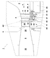
【解決手段】案内静翼ボックス17が複数の通路30を備えており、これらの通路が案内静翼ボックス17の作業上流側の領域31を案内静翼ボックス17の作業下流側の間隙7の領域32へ接続していること、および圧縮空気の圧力が高いために、圧縮空気(パージ空気)は開口部38を通って通路30に入り、通路30を通過し、圧縮空気がロータエアフォイル入口23には入ることができない領域内の第二の間隙7に入る開口部34を通って出て行く。
【選択図】図2
Description
2 燃焼室
4 ステータエアフォイル列
5 第一の間隙
6 ロータエアフォイル列
7 第二の間隙
8 第三の間隙
9 環状の間隙
10 第二のバーナー
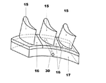
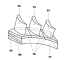
15 ステータエアフォイル
16 15の端部壁
17 案内静翼ボックス
20 ノズル
22 ロータエアフォイル
23 ロータエアフォイル入口
25 封止部材
26 固定されたフレーム
30 通路
31 案内静翼ボックスの運転上流側の領域
32 案内静翼ボックスの運転下流側の領域
34 30の開口部
35 高温ガス通路
36 17の側壁
37 封止部材
38 30の開口部
A 冷却空気
A2 22を通って排出される空気
F 高温ガス流
Claims (9)
- 複数の案内静翼を規定しているステータエアフォイル列(4)と、少なくとも一つの間隙(7)分だけステータエアフォイル列(4)から隔てられたロータエアフォイル列(6)を備えたガスタービン(1)であって、
ステータエアフォイル列(4)のステータエアフォイル(15)が、案内静翼ボックス(17)に接続されており、この案内静翼ボックスが、冷却流体(A)を捕集し、かつこの冷却流体をノズル(20)を通して前記間隙(7)内に排出して、冷却流体をロータエアフォイル入口(23)に入り込ませる様式のガスタービン(1)において、
前記案内静翼ボックス(17)が複数の通路(30)を備えており、これらの通路が案内静翼ボックス(17)の運転上流側の領域(31)を前記案内静翼ボックス(17)の運転下流側の前記間隙(7)の領域(32)へ接続していること、および
圧縮空気が通路(30)から、圧縮空気がロータエアフォイル入口(23)に入ることができない領域内の間隙(7)に入る開口部(34)を通って出ていくことを特徴とするガスタービン(1)。 - ロータエアフォイル列(6)に面した通路(30)の前記開口部(34)が、
ロータエアフォイル入口(23)に比べて、高温ガス通路(35)にほぼ同じく近いか、あるいはロータエアフォイル入口(23)に比べて、高温ガス通路(35)に近いことを特徴とする請求項1記載のガスタービン(1)。 - 前記通路(30)が案内静翼ボックス(17)の側壁においてスロットにより規定されていることを特徴とする請求項1に記載のガスタービン(1)。
- 前記通路(30)が案内静翼ボックス(17)の内部で延びていることを特徴とする請求項1に記載のガスタービン(1)。
- 前記通路(30)が導管により規定されていることを特徴とする請求項4に記載のガスタービン(1)。
- 封止部材(37)が、案内静翼ボックス(17)と固定されたフレーム(26)の間で、ロータエアフォイル列(6)と対向した通路(30)の開口部(38)の運転下流側に設けられていることを特徴とする請求項1に記載のガスタービン(1)。
- ステータエアフォイル列(4)の運転上流側には別の間隙(5)が設けられており、通路が間隙(7)と別の間隙(5)に隣接した領域の間に設けられていることを特徴とする請求項1に記載のガスタービン(1)。
- ステータエアフォイル列(4)の運転上流側には燃焼室(2)が設けられており、ステータエアフォイル列(4)が別の間隙(5)の分だけ燃焼室(2)から隔てられていることを特徴とする請求項7に記載のガスタービン(1)。
- ロータエアフォイル列(6)に面した通路(30)の前記開口部(34)が、前記ノズル(20)に比べて高温ガス通路(30)に近いことを特徴とする請求項1に記載のガスタービン(1)。
Applications Claiming Priority (2)
| Application Number | Priority Date | Filing Date | Title |
|---|---|---|---|
| EP09171142.4 | 2009-09-23 | ||
| EP09171142.4A EP2302173B8 (en) | 2009-09-23 | 2009-09-23 | Gas turbine |
Publications (3)
| Publication Number | Publication Date |
|---|---|
| JP2011069366A true JP2011069366A (ja) | 2011-04-07 |
| JP2011069366A5 JP2011069366A5 (ja) | 2015-09-03 |
| JP5840353B2 JP5840353B2 (ja) | 2016-01-06 |
Family
ID=41820796
Family Applications (1)
| Application Number | Title | Priority Date | Filing Date |
|---|---|---|---|
| JP2010212081A Expired - Fee Related JP5840353B2 (ja) | 2009-09-23 | 2010-09-22 | ガスタービン |
Country Status (3)
| Country | Link |
|---|---|
| US (1) | US8979479B2 (ja) |
| EP (1) | EP2302173B8 (ja) |
| JP (1) | JP5840353B2 (ja) |
Cited By (1)
| Publication number | Priority date | Publication date | Assignee | Title |
|---|---|---|---|---|
| JP2012215817A (ja) * | 2011-03-28 | 2012-11-08 | Fujifilm Corp | セルロースアシレートフィルム、位相差フィルム、偏光板および液晶表示装置 |
Families Citing this family (5)
| Publication number | Priority date | Publication date | Assignee | Title |
|---|---|---|---|---|
| US9970299B2 (en) * | 2015-09-16 | 2018-05-15 | General Electric Company | Mixing chambers for turbine wheel space cooling |
| US10125632B2 (en) | 2015-10-20 | 2018-11-13 | General Electric Company | Wheel space purge flow mixing chamber |
| US10132195B2 (en) | 2015-10-20 | 2018-11-20 | General Electric Company | Wheel space purge flow mixing chamber |
| US10519873B2 (en) | 2016-04-06 | 2019-12-31 | General Electric Company | Air bypass system for rotor shaft cooling |
| US10641174B2 (en) | 2017-01-18 | 2020-05-05 | General Electric Company | Rotor shaft cooling |
Citations (6)
| Publication number | Priority date | Publication date | Assignee | Title |
|---|---|---|---|---|
| JPS57116102A (en) * | 1980-08-06 | 1982-07-20 | Rolls Royce | Stationary blade assembly for turbo apparatus |
| JPS5810123A (ja) * | 1981-06-11 | 1983-01-20 | ゼネラル・エレクトリツク・カンパニイ | タ−ビン羽根用冷却空気噴射器 |
| GB2246836A (en) * | 1981-05-07 | 1992-02-12 | Rolls Royce | Fluid flow valve |
| JPH07139372A (ja) * | 1993-07-15 | 1995-05-30 | Soc Natl Etud Constr Mot Aviat <Snecma> | ターボジェットエンジン |
| US20060222486A1 (en) * | 2005-04-01 | 2006-10-05 | Maguire Alan R | Cooling system for a gas turbine engine |
| JP2010196501A (ja) * | 2009-02-23 | 2010-09-09 | Mitsubishi Heavy Ind Ltd | タービンの冷却構造およびガスタービン |
Family Cites Families (7)
| Publication number | Priority date | Publication date | Assignee | Title |
|---|---|---|---|---|
| FR1351268A (fr) | 1963-03-20 | 1964-01-31 | Rolls Royce | Moteur à turbine à gaz comportant un aubage de turbine refroidi |
| US4882902A (en) * | 1986-04-30 | 1989-11-28 | General Electric Company | Turbine cooling air transferring apparatus |
| US4666368A (en) * | 1986-05-01 | 1987-05-19 | General Electric Company | Swirl nozzle for a cooling system in gas turbine engines |
| US5135354A (en) * | 1990-09-14 | 1992-08-04 | United Technologies Corporation | Gas turbine blade and disk |
| DE10330471A1 (de) * | 2003-07-05 | 2005-02-03 | Alstom Technology Ltd | Vorrichtung zum Abscheiden von Fremdpartikeln aus der den Laufschaufeln einer Turbine zuführbaren Kühlluft |
| US7189055B2 (en) * | 2005-05-31 | 2007-03-13 | Pratt & Whitney Canada Corp. | Coverplate deflectors for redirecting a fluid flow |
| US8262342B2 (en) * | 2008-07-10 | 2012-09-11 | Honeywell International Inc. | Gas turbine engine assemblies with recirculated hot gas ingestion |
-
2009
- 2009-09-23 EP EP09171142.4A patent/EP2302173B8/en active Active
-
2010
- 2010-09-15 US US12/882,409 patent/US8979479B2/en not_active Expired - Fee Related
- 2010-09-22 JP JP2010212081A patent/JP5840353B2/ja not_active Expired - Fee Related
Patent Citations (6)
| Publication number | Priority date | Publication date | Assignee | Title |
|---|---|---|---|---|
| JPS57116102A (en) * | 1980-08-06 | 1982-07-20 | Rolls Royce | Stationary blade assembly for turbo apparatus |
| GB2246836A (en) * | 1981-05-07 | 1992-02-12 | Rolls Royce | Fluid flow valve |
| JPS5810123A (ja) * | 1981-06-11 | 1983-01-20 | ゼネラル・エレクトリツク・カンパニイ | タ−ビン羽根用冷却空気噴射器 |
| JPH07139372A (ja) * | 1993-07-15 | 1995-05-30 | Soc Natl Etud Constr Mot Aviat <Snecma> | ターボジェットエンジン |
| US20060222486A1 (en) * | 2005-04-01 | 2006-10-05 | Maguire Alan R | Cooling system for a gas turbine engine |
| JP2010196501A (ja) * | 2009-02-23 | 2010-09-09 | Mitsubishi Heavy Ind Ltd | タービンの冷却構造およびガスタービン |
Cited By (1)
| Publication number | Priority date | Publication date | Assignee | Title |
|---|---|---|---|---|
| JP2012215817A (ja) * | 2011-03-28 | 2012-11-08 | Fujifilm Corp | セルロースアシレートフィルム、位相差フィルム、偏光板および液晶表示装置 |
Also Published As
| Publication number | Publication date |
|---|---|
| US8979479B2 (en) | 2015-03-17 |
| JP5840353B2 (ja) | 2016-01-06 |
| EP2302173A1 (en) | 2011-03-30 |
| EP2302173B8 (en) | 2017-08-02 |
| US20110070077A1 (en) | 2011-03-24 |
| EP2302173B1 (en) | 2017-03-01 |
Similar Documents
| Publication | Publication Date | Title |
|---|---|---|
| CN103195507B (zh) | 涡轮喷嘴区划冷却系统 | |
| US8550774B2 (en) | Turbine arrangement and method of cooling a shroud located at the tip of a turbine blade | |
| JP5584410B2 (ja) | マルチソース型ガスタービン冷却 | |
| JP4981970B2 (ja) | ガスタービン | |
| JP5840353B2 (ja) | ガスタービン | |
| US8783044B2 (en) | Turbine stator nozzle cooling structure | |
| JP6283173B2 (ja) | ガスタービンシステム用の冷却組立体 | |
| US9534536B2 (en) | Turbine flow modulation for part load performance | |
| JP2011153540A (ja) | 分割環冷却構造およびガスタービン | |
| CN105026697B (zh) | 径向扩散器排气系统 | |
| JP2009250605A (ja) | ガスタービンエンジン用の再熱燃焼器 | |
| JP2017198184A (ja) | ロータとステータとの間にリムシールを有するガスタービンエンジン | |
| JP2013164071A (ja) | ターボ機械のための連絡管シールアセンブリ | |
| CN102477872B (zh) | 轴向流类型的燃气轮机 | |
| CA2794035C (en) | Axial compressor for fluid-flow machines | |
| JP2013249835A (ja) | タービンシステムのバケット用冷却組立体及び冷却方法 | |
| JP5216802B2 (ja) | 2軸式ガスタービンの冷却空気供給構造 | |
| US20150159873A1 (en) | Compressor discharge casing assembly | |
| JP2014074406A (ja) | 冷却通路を備えた固体シール | |
| JP6961340B2 (ja) | 回転機械 | |
| JP2013213492A (ja) | 移行ノズル燃焼システム | |
| CN116066243A (zh) | 用于功率设施的燃气涡轮组件及其操作方法 | |
| JP2006336464A (ja) | ガスタービンの静翼、及びガスタービン | |
| JP2011241839A (ja) | ガスタービンの静翼、及びガスタービン | |
| US10837300B2 (en) | Seal pressurization in box shroud |
Legal Events
| Date | Code | Title | Description |
|---|---|---|---|
| RD03 | Notification of appointment of power of attorney |
Free format text: JAPANESE INTERMEDIATE CODE: A7423 Effective date: 20130628 |
|
| RD04 | Notification of resignation of power of attorney |
Free format text: JAPANESE INTERMEDIATE CODE: A7424 Effective date: 20130703 |
|
| A621 | Written request for application examination |
Free format text: JAPANESE INTERMEDIATE CODE: A621 Effective date: 20130826 |
|
| A977 | Report on retrieval |
Free format text: JAPANESE INTERMEDIATE CODE: A971007 Effective date: 20140325 |
|
| A131 | Notification of reasons for refusal |
Free format text: JAPANESE INTERMEDIATE CODE: A131 Effective date: 20140407 |
|
| A601 | Written request for extension of time |
Free format text: JAPANESE INTERMEDIATE CODE: A601 Effective date: 20140707 |
|
| A602 | Written permission of extension of time |
Free format text: JAPANESE INTERMEDIATE CODE: A602 Effective date: 20140710 |
|
| A601 | Written request for extension of time |
Free format text: JAPANESE INTERMEDIATE CODE: A601 Effective date: 20140807 |
|
| A602 | Written permission of extension of time |
Free format text: JAPANESE INTERMEDIATE CODE: A602 Effective date: 20140812 |
|
| A521 | Written amendment |
Free format text: JAPANESE INTERMEDIATE CODE: A523 Effective date: 20140822 |
|
| A524 | Written submission of copy of amendment under section 19 (pct) |
Free format text: JAPANESE INTERMEDIATE CODE: A524 Effective date: 20140822 |
|
| A131 | Notification of reasons for refusal |
Free format text: JAPANESE INTERMEDIATE CODE: A131 Effective date: 20150126 |
|
| A524 | Written submission of copy of amendment under section 19 (pct) |
Free format text: JAPANESE INTERMEDIATE CODE: A524 Effective date: 20150414 |
|
| TRDD | Decision of grant or rejection written | ||
| A01 | Written decision to grant a patent or to grant a registration (utility model) |
Free format text: JAPANESE INTERMEDIATE CODE: A01 Effective date: 20151013 |
|
| A61 | First payment of annual fees (during grant procedure) |
Free format text: JAPANESE INTERMEDIATE CODE: A61 Effective date: 20151111 |
|
| R150 | Certificate of patent or registration of utility model |
Ref document number: 5840353 Country of ref document: JP Free format text: JAPANESE INTERMEDIATE CODE: R150 |
|
| S533 | Written request for registration of change of name |
Free format text: JAPANESE INTERMEDIATE CODE: R313533 |
|
| R350 | Written notification of registration of transfer |
Free format text: JAPANESE INTERMEDIATE CODE: R350 |
|
| S111 | Request for change of ownership or part of ownership |
Free format text: JAPANESE INTERMEDIATE CODE: R313113 |
|
| R350 | Written notification of registration of transfer |
Free format text: JAPANESE INTERMEDIATE CODE: R350 |
|
| LAPS | Cancellation because of no payment of annual fees |