JP2011027556A - Multi-functional feed-screw-type dovetail stage - Google Patents
Multi-functional feed-screw-type dovetail stage Download PDFInfo
- Publication number
- JP2011027556A JP2011027556A JP2009173855A JP2009173855A JP2011027556A JP 2011027556 A JP2011027556 A JP 2011027556A JP 2009173855 A JP2009173855 A JP 2009173855A JP 2009173855 A JP2009173855 A JP 2009173855A JP 2011027556 A JP2011027556 A JP 2011027556A
- Authority
- JP
- Japan
- Prior art keywords
- feed screw
- dovetail stage
- sliding
- screw
- handle
- Prior art date
- Legal status (The legal status is an assumption and is not a legal conclusion. Google has not performed a legal analysis and makes no representation as to the accuracy of the status listed.)
- Granted
Links
Images
Classifications
-
- G—PHYSICS
- G02—OPTICS
- G02B—OPTICAL ELEMENTS, SYSTEMS OR APPARATUS
- G02B7/00—Mountings, adjusting means, or light-tight connections, for optical elements
- G02B7/003—Alignment of optical elements
- G02B7/004—Manual alignment, e.g. micromanipulators
-
- F—MECHANICAL ENGINEERING; LIGHTING; HEATING; WEAPONS; BLASTING
- F16—ENGINEERING ELEMENTS AND UNITS; GENERAL MEASURES FOR PRODUCING AND MAINTAINING EFFECTIVE FUNCTIONING OF MACHINES OR INSTALLATIONS; THERMAL INSULATION IN GENERAL
- F16M—FRAMES, CASINGS OR BEDS OF ENGINES, MACHINES OR APPARATUS, NOT SPECIFIC TO ENGINES, MACHINES OR APPARATUS PROVIDED FOR ELSEWHERE; STANDS; SUPPORTS
- F16M11/00—Stands or trestles as supports for apparatus or articles placed thereon ; Stands for scientific apparatus such as gravitational force meters
- F16M11/02—Heads
- F16M11/04—Means for attachment of apparatus; Means allowing adjustment of the apparatus relatively to the stand
- F16M11/043—Allowing translations
-
- F—MECHANICAL ENGINEERING; LIGHTING; HEATING; WEAPONS; BLASTING
- F16—ENGINEERING ELEMENTS AND UNITS; GENERAL MEASURES FOR PRODUCING AND MAINTAINING EFFECTIVE FUNCTIONING OF MACHINES OR INSTALLATIONS; THERMAL INSULATION IN GENERAL
- F16M—FRAMES, CASINGS OR BEDS OF ENGINES, MACHINES OR APPARATUS, NOT SPECIFIC TO ENGINES, MACHINES OR APPARATUS PROVIDED FOR ELSEWHERE; STANDS; SUPPORTS
- F16M11/00—Stands or trestles as supports for apparatus or articles placed thereon ; Stands for scientific apparatus such as gravitational force meters
- F16M11/02—Heads
- F16M11/18—Heads with mechanism for moving the apparatus relatively to the stand
-
- F—MECHANICAL ENGINEERING; LIGHTING; HEATING; WEAPONS; BLASTING
- F16—ENGINEERING ELEMENTS AND UNITS; GENERAL MEASURES FOR PRODUCING AND MAINTAINING EFFECTIVE FUNCTIONING OF MACHINES OR INSTALLATIONS; THERMAL INSULATION IN GENERAL
- F16M—FRAMES, CASINGS OR BEDS OF ENGINES, MACHINES OR APPARATUS, NOT SPECIFIC TO ENGINES, MACHINES OR APPARATUS PROVIDED FOR ELSEWHERE; STANDS; SUPPORTS
- F16M2200/00—Details of stands or supports
- F16M2200/02—Locking means
- F16M2200/025—Locking means for translational movement
- F16M2200/027—Locking means for translational movement by friction
-
- Y—GENERAL TAGGING OF NEW TECHNOLOGICAL DEVELOPMENTS; GENERAL TAGGING OF CROSS-SECTIONAL TECHNOLOGIES SPANNING OVER SEVERAL SECTIONS OF THE IPC; TECHNICAL SUBJECTS COVERED BY FORMER USPC CROSS-REFERENCE ART COLLECTIONS [XRACs] AND DIGESTS
- Y10—TECHNICAL SUBJECTS COVERED BY FORMER USPC
- Y10T—TECHNICAL SUBJECTS COVERED BY FORMER US CLASSIFICATION
- Y10T74/00—Machine element or mechanism
- Y10T74/18—Mechanical movements
- Y10T74/18568—Reciprocating or oscillating to or from alternating rotary
- Y10T74/18576—Reciprocating or oscillating to or from alternating rotary including screw and nut
- Y10T74/18752—Manually driven
-
- Y—GENERAL TAGGING OF NEW TECHNOLOGICAL DEVELOPMENTS; GENERAL TAGGING OF CROSS-SECTIONAL TECHNOLOGIES SPANNING OVER SEVERAL SECTIONS OF THE IPC; TECHNICAL SUBJECTS COVERED BY FORMER USPC CROSS-REFERENCE ART COLLECTIONS [XRACs] AND DIGESTS
- Y10—TECHNICAL SUBJECTS COVERED BY FORMER USPC
- Y10T—TECHNICAL SUBJECTS COVERED BY FORMER US CLASSIFICATION
- Y10T74/00—Machine element or mechanism
- Y10T74/20—Control lever and linkage systems
- Y10T74/20207—Multiple controlling elements for single controlled element
- Y10T74/20341—Power elements as controlling elements
- Y10T74/20354—Planar surface with orthogonal movement only
-
- Y—GENERAL TAGGING OF NEW TECHNOLOGICAL DEVELOPMENTS; GENERAL TAGGING OF CROSS-SECTIONAL TECHNOLOGIES SPANNING OVER SEVERAL SECTIONS OF THE IPC; TECHNICAL SUBJECTS COVERED BY FORMER USPC CROSS-REFERENCE ART COLLECTIONS [XRACs] AND DIGESTS
- Y10—TECHNICAL SUBJECTS COVERED BY FORMER USPC
- Y10T—TECHNICAL SUBJECTS COVERED BY FORMER US CLASSIFICATION
- Y10T74/00—Machine element or mechanism
- Y10T74/20—Control lever and linkage systems
- Y10T74/20207—Multiple controlling elements for single controlled element
- Y10T74/20372—Manual controlling elements
- Y10T74/20378—Planar surface with orthogonal movement or rotation
Landscapes
- Engineering & Computer Science (AREA)
- General Engineering & Computer Science (AREA)
- Physics & Mathematics (AREA)
- Mechanical Engineering (AREA)
- General Physics & Mathematics (AREA)
- Optics & Photonics (AREA)
- Details Of Measuring And Other Instruments (AREA)
- Transmission Devices (AREA)
- Machine Tool Units (AREA)
Abstract
【課題】送りネジ式アリ溝ステージの性能を向上させ、送りネジ式アリ溝ステージに複数の機能を容易追加して使い勝手を改善した多機能送りネジ式アリ溝ステージを提供する。
【解決手段】多機能送りネジ式アリ溝ステージ1は、両端部にハンドル8との連結部を有する雄ネジ棒7と、固定部品2の両側にそれぞれ設けられ、雄ネジ棒7を回転自在に保持する第1支持台9及び第2支持台10と、連結部を介して雄ネジ棒7と着脱自在に連結して雄ネジ棒7を回転させるハンドル8と、を備え、摺動部品3は、固定部品2と接続する雌ネジ筒が移動して第1支持台9及び第2支持台10に当接するまで移動する。
【選択図】図1Provided is a multi-function feed screw dovetail stage in which the performance of a feed screw dovetail stage is improved and a plurality of functions are easily added to the feed screw dovetail stage to improve usability.
A multi-function feed screw dovetail stage 1 is provided on both ends of a male threaded rod 7 having a connecting portion with a handle 8 at both ends and a fixed component 2, and the male threaded rod 7 is rotatable. The sliding part 3 includes a first support base 9 and a second support base 10 that are held, and a handle 8 that is detachably connected to the male screw rod 7 via a connecting portion to rotate the male screw rod 7. The internal thread cylinder connected to the fixed component 2 moves and moves until it contacts the first support base 9 and the second support base 10.
[Selection] Figure 1
Description
本発明は、多機能送りネジ式アリ溝ステージに係り、特に、雌ネジ筒が接続する摺動部品と、雄ネジ棒が接続する固定部品とが係合され、ハンドル操作により雄ネジ棒を回転させて雌ネジ筒を移動させることで摺動部品を摺動させ、取り付けられた精密機器の位置調整を行う送りネジ式アリ溝ステージに関する。 The present invention relates to a multi-function feed screw dovetail stage, and in particular, a sliding part to which a female screw cylinder is connected and a fixed part to which a male screw bar is connected are engaged, and the male screw bar is rotated by a handle operation. The present invention relates to a feed screw type dovetail stage that slides a sliding component by moving a female screw cylinder and adjusts the position of an attached precision instrument.
CCDカメラやセンサなどの電機・電子機器、レンズや顕微鏡等の光学機器、LEDなどの照明機器といった精密機器は、取り付けに際し、位置決めやピント合わせのために位置調整しなければならない。また、取り付け後において、さらにその位置を微調整する場合も発生する。 Precision devices such as electrical devices such as CCD cameras and sensors, optical devices such as lenses and microscopes, and illumination devices such as LEDs must be adjusted for positioning and focusing. Further, there may be a case where the position is further finely adjusted after the attachment.
これらの精密機器は、アリ溝式ステージと称される装置に設置されて位置調整される。このアリ溝式ステージは、機器が取付けられる摺動部品と、土台に固定される固定部品とが摺動機構を介して連結され、ハンドル操作により摺動部品を固定部品に対して手動で摺動させるのが一般的である。このアリ溝式ステージには、使用目的に応じて多様な形式があり、例えば、1方向に摺動するX軸アリ溝式ステージ、略直交する2方向に摺動するXY軸アリ溝式ステージ、上下方向に摺動するZ軸アリ溝式ステージ、回転して摺動する回転ステージなどがある。そして、このアリ溝式ステージに組み込まれる駆動方式には、例えば、送りネジにより駆動する送りネジ式アリ溝ステージ、ラック及びピニオンギアにより駆動するラック及びピニオンギア式アリ溝ステージなどがある。 These precision instruments are installed and adjusted in an apparatus called a dovetail stage. In this dovetail stage, a sliding part to which equipment is attached and a fixed part fixed to the base are connected via a sliding mechanism, and the sliding part is manually slid with respect to the fixed part by a handle operation. It is common to make it. There are various types of dovetail stage depending on the purpose of use. For example, an X-axis dovetail stage that slides in one direction, an XY-axis dovetail stage that slides in two directions substantially perpendicular to each other, There are a Z-axis dovetail stage that slides in the vertical direction, a rotary stage that rotates and slides, and the like. The drive system incorporated in the dovetail stage includes, for example, a feed screw dovetail stage driven by a feed screw, a rack and pinion gear dovetail stage driven by a rack and pinion gear, and the like.
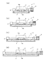
図9に、従来の一般的な送りネジ式アリ溝ステージを示す。図9(b)は、送りネジ式アリ溝ステージ100の側面図であり、図9(a)は、図9(b)をG−G方向からみた平面図であり、図9(c)は、図9(b)をH−H方向からみた平面図である。送りネジ式アリ溝ステージ100は、アリ104を有する摺動部品103、アリ溝105を有する固定部品102、摺動機構である雄ネジ棒107及び雌ネジ筒106、ハンドル108、及び摺動固定ネジ112から構成される。そして、摺動部品103側には目盛板113bが取り付き、固定部品102側には、目盛板113aが取り付く。この雄ネジ棒107を雌ネジ筒106に係合させ、ハンドル108を回転させることで摺動部品103が固定部品102に対して摺動する。摺動固定ネジ112は、任意の位置で摺動部品103を固定部品102に対して固定する。
FIG. 9 shows a conventional general feed screw type dovetail stage. 9B is a side view of the feed screw
この送りネジ式アリ溝ステージ100の雄ネジ棒107は、一端が固定部品102に取付けられて固定され、他端は自由端となる片持梁となっている。また、この送りネジ式アリ溝ステージ100の固定部品102に対する摺動部品103の移動距離は、雌ネジ筒106が、固定部品102の一方の端部に取り付けられたストッパ板109、及び固定部品102の他方の端部に設けられたワッシャ110に当接することで決定される。また、雄ネジ棒107は、送りネジ式アリ溝ステージ100に組み込まれているため交換することはできない。さらに、ハンドル108や目盛板113a、113bは、送りネジ式アリ溝ステージ100の機構上その位置が固定されている。
One end of the
一方、特許文献1には、回転テーブルがベースに対して回転する回転ステージが開示されている。ここでは、回転テーブルとベースの一方に送りねじが配設され、他方に送りねじに螺合するナットが配設され、これらの送りねじ機構により、回転テーブルがベースに対して正転または逆転し得ることが記載されている。
On the other hand,
従来の送りネジ式アリ溝ステージは、雄ネジ棒の一端が固定され、他端が自由端である片持梁であり、雄ネジ棒は先端に向けて自重により撓みが大きくなる。このため、雌ネジ筒が長くなるほど雌ネジ筒と雄ネジ棒との係合の際にこじれが発生する場合があり、送りネジ式アリ溝ステージの性能が低下する虞がある。 A conventional feed screw dovetail stage is a cantilever in which one end of a male screw rod is fixed and the other end is a free end, and the male screw rod is flexed by its own weight toward the tip. For this reason, the longer the female screw cylinder is, the more likely the twisting occurs when the female screw cylinder and the male screw rod are engaged, and the performance of the feed screw dovetail stage may deteriorate.
また、雄ネジ棒とハンドルとは固定されたまま送りネジ式アリ溝ステージの製品内部に組み込まれている。このため、ユーザが雄ネジ棒を交換することができず機能性に欠けるステージとなっている。 Further, the male screw rod and the handle are fixed and incorporated in the product of the feed screw dovetail stage. For this reason, the user cannot replace the male threaded rod, and the stage lacks functionality.
さらに、ハンドル、摺動固定ネジ、及び目盛板の位置は製品に固定されているためその位置を変えることはできない。また、摺動部品の移動距離の異なるバリエーションから選択することができない。このため、ユーザにとっては使い勝手が悪いステージとなっている。 Furthermore, since the positions of the handle, the slide fixing screw, and the scale plate are fixed to the product, their positions cannot be changed. Moreover, it cannot select from the variation from which the moving distance of a sliding component differs. For this reason, it is a stage that is inconvenient for the user.
本願の目的は、かかる課題を解決し、送りネジ式アリ溝ステージの性能を向上させ、送りネジ式アリ溝ステージに複数の機能を容易に追加して使い勝手を改善した多機能送りネジ式アリ溝ステージを提供することである。 The purpose of this application is to solve this problem, improve the performance of the feed screw dovetail stage, and easily add multiple functions to the feed screw dovetail stage to improve usability. Is to provide a stage.
上記目的を達成するため、本発明に係る多機能送りネジ式アリ溝ステージは、雌ネジ筒が接続する摺動部品と、雄ネジ棒が接続する固定部品とが係合され、ハンドル操作により雄ネジ棒を回転させて雌ネジ筒を移動させることで摺動部品を摺動させ、取り付けられた精密機器の位置調整を行う送りネジ式アリ溝ステージにおいて、両端部にハンドルと連結する連結部を有する雄ネジ棒と、固定部品の両側にそれぞれ設けられ、雌ネジ筒の移動方向に関して固定部品の長さを規定し、雄ネジ棒を回転自在に保持する第1の支持台及び第2の支持台と、連結部を介して雄ネジ棒と着脱自在に連結して雄ネジ棒を回転させるハンドルと、を備えることを特徴とする。 In order to achieve the above object, the multi-function feed screw type dovetail stage according to the present invention is engaged with a sliding part to which a female screw cylinder is connected and a fixing part to which a male screw rod is connected, and the male part is operated by a handle operation. In the feed screw dovetail stage that adjusts the position of the precision equipment attached by sliding the sliding part by rotating the screw rod and moving the female screw cylinder, the connecting parts that connect with the handle at both ends A first support base and a second support which are provided on both sides of the male threaded rod and the fixed component, define the length of the stationary component with respect to the moving direction of the female threaded cylinder, and hold the male threaded rod rotatably. It is characterized by comprising a base and a handle that is detachably connected to the male threaded rod through the coupling portion and rotates the male threaded rod.
上記構成により、多機能送りネジ式アリ溝ステージは、雄ネジ棒が第1の支持台及び第2の支持台により単純梁として保持される。これにより、雄ネジ棒の撓み量が低減され、雌ネジ筒と雄ネジ棒とが係合する際のこじれが低減され、送りネジ式アリ溝ステージの性能を向上させることができる。また、ハンドルを雄ネジ棒のいずれの端部にも連結することができ、使用目的に合わせて使い勝手を容易に改善できる。また、固定部品の雌ネジ筒の移動方向の長さが第1の支持台及び第2の支持台の間隔により規定されることから、使用目的に合わせた送りネジ式アリ溝ステージの移動距離を有する多機能送りネジ式アリ溝ステージのバリエーションを揃えることができる。 With the above configuration, in the multi-function feed screw dovetail stage, the male screw rod is held as a simple beam by the first support base and the second support base. As a result, the amount of bending of the male screw rod is reduced, the twist when the female screw cylinder and the male screw rod are engaged is reduced, and the performance of the feed screw type dovetail stage can be improved. In addition, the handle can be connected to any end of the male threaded rod, and the usability can be easily improved according to the purpose of use. Further, since the length of the moving part of the female screw cylinder of the fixed part is defined by the distance between the first support base and the second support base, the movement distance of the feed screw type dovetail stage according to the purpose of use can be set. Variations of the multi-function feed screw dovetail stage can be provided.
また、多機能送りネジ式アリ溝ステージは、前記連結部が、雄ネジ棒の両端部に軸方向に設けられたネジ孔と、ハンドル内部に軸方向に挿入されて雄ネジ棒に設けられたネジ孔と係合するボルトとから構成され、摺動部は、雌ネジ筒に連結された凸状突出部が着脱自在な凹状挿入孔を有し、係合されたボルトを外し、凹状挿入孔から凸状突出部を外すことで、1回転当りの移動量が異なる複数の雄ネジ棒、及びその雄ネジ棒に対応する雌ネジ筒が交換自在に選択されることが好ましい。これにより、1回転当りの移動量が異なる複数の雄ネジ棒、及びその雄ネジ棒に対応する雌ネジ筒が交換自在に選択でき、多機能送りネジ式アリ溝ステージの使い勝手を容易に改善できる。また、ハンドルを雄ネジ棒のいずれの端部にも連結することができ、使用目的に合わせて使い勝手を容易に改善できる。 Further, in the multi-function feed screw dovetail stage, the connecting portion is provided on the male screw rod by being inserted in the axial direction inside the handle in the axial direction with screw holes provided at both ends of the male screw rod. The sliding portion has a concave insertion hole in which the convex protrusion connected to the female screw cylinder is detachable, and the engaged bolt is removed to form a concave insertion hole. It is preferable that a plurality of male screw rods having different movement amounts per rotation and a female screw cylinder corresponding to the male screw rod are selected so as to be interchangeable by removing the convex projecting portion. As a result, a plurality of male screw rods having different movement amounts per rotation and a female screw cylinder corresponding to the male screw rod can be selected interchangeably, and the usability of the multi-function feed screw dovetail stage can be easily improved. . In addition, the handle can be connected to any end of the male threaded rod, and the usability can be easily improved according to the purpose of use.
また、多機能送りネジ式アリ溝ステージは、摺動部品が、摺動部品の移動方向と交差する方向の断面に逆三角形の突出部、及び突出部を形成する縦方向の溝部とを有し、突出部まで貫通する摺動固定ネジ用孔に摺動固定ネジをねじ込んで突出部に突き当て、突出部を対向する固定部品に傾斜させ、摺動部品を固定部品に対して固定することが好ましい。これにより、摺動固定ネジを使用目的に合わせて両側面のいずれか、又は両側面に同時に取付けて使用目的に合わせて使い勝手を容易に改善できる。 In addition, the multi-function feed screw dovetail stage has a sliding part having an inverted triangular protrusion on a cross section in a direction crossing the moving direction of the sliding part, and a vertical groove part forming the protrusion. A sliding fixing screw can be screwed into a hole for a sliding fixing screw that penetrates to the protruding portion, abuts against the protruding portion, the protruding portion is inclined to an opposing fixing component, and the sliding component is fixed to the fixing component. preferable. As a result, it is possible to easily improve the usability according to the purpose of use by attaching the sliding fixing screw to either one of the side surfaces according to the purpose of use or simultaneously attaching to both sides.
また、多機能送りネジ式アリ溝ステージは、目盛板、及び固定部品に対する摺動部品の位置を固定する摺動固定ネジが、摺動部品の移動方向と交差する方向の摺動部品の側面の双方に設けられることが好ましい。これにより、摺動固定ネジ及び目盛板を使用目的に合わせた側面に取付け使用目的に合わせて使い勝手を容易に改善できる。 In addition, the multi-function feed screw dovetail stage has a scale plate and a sliding fixing screw that fixes the position of the sliding component with respect to the fixed component. It is preferable to be provided on both sides. Accordingly, the sliding fixing screw and the scale plate are attached to the side face according to the purpose of use, and the usability can be easily improved according to the purpose of use.
また、多機能送りネジ式アリ溝ステージは、雄ネジ棒が、第1の支持台及び第2の支持台の双方でそれぞれ第1のハンドル及び第2のハンドルに連結されることが好ましい。これにより、ハンドルを雄ネジ棒の両端部に同時に連結でき、使用目的に合わせてハンドル操作の使い勝手を容易に改善できる。 In the multi-function feed screw dovetail stage, the male threaded rod is preferably connected to the first handle and the second handle, respectively, on both the first support base and the second support base. As a result, the handle can be connected to both ends of the male screw rod at the same time, and the ease of use of the handle can be easily improved according to the purpose of use.
また、多機能送りネジ式アリ溝ステージは、雄ネジ棒が、略鉛直方向に向けられ、第1支持台が土台に固定され、第2の支持台がハンドルに連結されることが好ましい。これにより、多機能送りネジ式アリ溝ステージを使用目的に合わせて縦方向に使用でき、使用目的に合わせて使い勝手を容易に改善できる。 In the multi-function feed screw dovetail stage, it is preferable that the male screw rod is directed in a substantially vertical direction, the first support base is fixed to the base, and the second support base is connected to the handle. Accordingly, the multi-function feed screw dovetail stage can be used in the vertical direction according to the purpose of use, and the usability can be easily improved according to the purpose of use.
また、多機能送りネジ式アリ溝ステージは,1つの固定部品に対して複数の摺動部品が摺動方向に沿って並置されることが好ましい。また、多機能送りネジ式アリ溝ステージは、1組の固定部品及び摺動部品が摺動方向に沿って連結されて複数組並置されることが好ましい。これにより、1箇所に複数の摺動部品を並置し、使用目的に合わせて複数の摺動部品を選択して使用することができ、使用目的に合わせて使い勝手を容易に改善できる。 In the multi-function feed screw dovetail stage, it is preferable that a plurality of sliding parts are juxtaposed along the sliding direction with respect to one fixed part. In addition, it is preferable that a plurality of sets of the multi-function feed screw dovetail stage are juxtaposed by connecting a set of fixed parts and sliding parts along the sliding direction. Thereby, a plurality of sliding parts can be juxtaposed in one place, and a plurality of sliding parts can be selected and used according to the purpose of use, and the usability can be easily improved according to the purpose of use.
さらに、多機能送りネジ式アリ溝ステージは,前記並置された複数の摺動部品が、少なくともハンドル位置、雄ネジ棒の1回転当りの移動量、又は最大移動距離のいずれかが異なることが好ましい。これにより、1箇所に設置した複数の摺動部品のハンドル位置、雄ネジ棒の1回転当りの移動量、又は最大移動距離を変えたバリエーションを揃えることができる。 Further, in the multi-function feed screw dovetail stage, it is preferable that the plurality of juxtaposed sliding parts differ in at least one of a handle position, a moving amount per one rotation of the male screw rod, or a maximum moving distance. . Thereby, the variation which changed the handle | steering-wheel position of the several sliding components installed in one place, the moving amount per rotation of a male screw rod, or the maximum moving distance can be arranged.
以上のように、本発明に係る多機能送りネジ式アリ溝ステージによれば、送りネジ式アリ溝ステージの性能を向上させ、送りネジ式アリ溝ステージに複数の機能を容易に追加して使い勝手を改善した多機能送りネジ式アリ溝ステージを提供することができる。 As described above, according to the multi-function feed screw dovetail stage according to the present invention, the performance of the feed screw dovetail stage is improved, and a plurality of functions can be easily added to the feed screw dovetail stage for ease of use. It is possible to provide a multi-function feed screw type dovetail stage which is improved.
以下に、図面を用いて本発明に係る多機能送りネジ式アリ溝ステージの実施形態につき、詳細に説明する。 Hereinafter, embodiments of the multi-function feed screw dovetail stage according to the present invention will be described in detail with reference to the drawings.
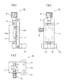
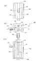
図1,図2,及び図3に、本発明に係る多機能送りネジ式アリ溝ステージの1つの実施形態の概略構成を示す。図1(a)は、多機能送りネジ式アリ溝ステージ1の正面図であり、図1(b)は、図1(a)をA−A方向から見た平面図であり、図1(c)は、図1(a)をB−B方向から見た底面図である。また、図2(a)は、図1(b)をC−C方向から見た側面図であり、図2(b)は、図1(b)をD−D方向から見た側面図であり、図2(c)は、図1(b)のE−E断面図である。さらに、図3は、図2(b)のF−F断面図である。多機能送りネジ式アリ溝ステージ1は、固定部品2、摺動部品3、雌ネジ筒6、雄ネジ棒7、ハンドル8、第1支持台9、第2支持台10、及びハンドル接続用ボルト11から構成される。
1, 2, and 3 show a schematic configuration of one embodiment of a multi-function feed screw dovetail stage according to the present invention. 1A is a front view of the multi-function feed
精密機器(図示せず)は、図1(b)に示すように、摺動部品3に設けられた精密機器取付け用孔15に挿入されるボルト(図示せず)を介して多機能送りネジ式アリ溝ステージ1に固定される。また、多機能送りネジ式アリ溝ステージ1は、図1(c)に示すように、固定部品2に設けられた土台固定用締結孔14に挿入されるボルト(図示せず)を介して土台(図示せず)に締結される。
As shown in FIG. 1 (b), the precision instrument (not shown) is a multi-function feed screw via a bolt (not shown) inserted into a precision
図3に示すように、多機能送りネジ式アリ溝ステージ1は、雌ネジ筒6に設けられた凸状突出部18を摺動部品3に設けられた凹状挿入孔26に挿入することで、雌ネジ筒6を摺動部品3に固定する。この凸状突出部18は凹状挿入孔26に着脱自在に挿入される。また、この雌ネジ筒6は筒の内側に雌ネジが切られ、雄ネジ棒7に切られた雄ネジと係合する。そして、ハンドル8の回転操作により雄ネジ棒7を回転させることで雌ネジ筒6を図3の左右の方向に移動させる。これにより、摺動部品3を固定部品2に対して摺動させ、取り付けられた精密機器(図示せず)の位置調整を行う。また、摺動部品3に取付けられた目盛板13aと、固定部品2に取付けられた目盛板13bとにより摺動部品3の固定部品2に対する移動量を計測する。
As shown in FIG. 3, the multi-function feed screw
図3に示すように、固定部品2は両端部を第1支持台9と第2支持台10とにより挟まれる。そして、第1支持台9及び第2支持台10は、図2(a)及び図2(b)に示すように支持台固定ボルト17a,17bによりそれぞれ固定部品2に固定される。
As shown in FIG. 3, the fixed
このハンドル8と雄ネジ棒7とを連結する連結部について説明する。この連結部は、ハンドル接続用孔16a,16b、及びハンドル接続用ボルト11から構成される。雄ネジ棒7は、雌ネジ筒6と係合する中央のねじ部19とネジが切られていない丸棒部20からなる。また、図3に示すように、雄ネジ棒7の丸棒部20にはハンドル接続用孔16a,16bが軸方向に設けられている。この雄ネジ棒7の丸棒部20は、図1(b)に示すように、第1支持台9及び第2支持台10にそれぞれ設けられた雄ネジ棒貫通孔21a,21bに挿入される。これにより、雄ネジ棒7は、第1支持台9及び第2支持台10に回転自在に保持される。すなわち、雄ネジ棒7は、第1支持台9及び第2支持台10により両端で支持される単純梁として機能する。これにより、雄ネジ棒7の撓み量が低減される。つまり、雌ネジ筒6と雄ネジ棒7との係合の際のねじ部のこじれが低減され、多機能送りネジ式アリ溝ステージ1の性能を向上させることができる。
A connecting portion for connecting the
ハンドル8には、その内部に雄ネジ棒7に設けられたハンドル接続用孔16と係合するハンドル接続用ボルト11が内蔵されている。そして、ハンドル接続用ボルト11をハンドル接続用孔16に係合することで、ハンドル8を多機能送りネジ式アリ溝ステージ1に連結することができる。この連結されたハンドル8により雄ネジ棒7を回転させる。
The
図4に、ハンドル8の取り付け位置のバリエーションを示す。図4(a)は、図3のハンドル8aの位置を示す側面図であり、図4(b)は、反対側にハンドル8bを取り付けた状態を示す側面図である。また、図4(c)は、両側にハンドル8a,8bを同時に取付けた状態を示す側面図である。このハンドル8は、ハンドル接続用ボルト11を緩めて外すことで雄ネジ棒7から自在に着脱できる。図3では、ハンドル接続用ボルト11はハンドル接続用孔16bに係合しているが、これを取り外してハンドル接続用孔16aに係合させても良い。なお、図3に示すように、ハンドル8が取り付いていないハンドル接続用孔16aには、化粧ボルト22が挿入されている。
FIG. 4 shows variations of the attachment position of the
このように、ハンドル8は、ハンドル接続用ボルト11により雄ネジ棒7に自在に着脱される。従って、ハンドル接続用孔16a又は16bに係合されたハンドル接続用ボルト11の着脱により、複数の雄ネジ棒7のなかから選択して交換できる。例えば、雄ネジ棒7の1回転当りの移動量は、5mmを標準として、2mm、10mmなどのバリエーションがあるが、これらのバリエーションから使用勝手に合わせて選択し、或いは交換することができる。上述したように、この雄ネジ棒7に対応する雌ネジ筒6についても、その凸状突出部18を摺動部品3に設けられた凹状挿入孔26に着脱自在に挿入できるため、雄ネジ棒7と対となって交換することができる。
Thus, the
図5(a)から図5(d)に、多機能送りネジ式アリ溝ステージ1の第1の実施例として、測定距離のバリエーションの例を示す。摺動部品3は、雌ネジ筒6が移動して第1支持台9及び第2支持台10に当接するまで移動する。従って、第1支持台9と第2支持台10とに挟まれた固定部品2の軸方向の長さを変えることで使用勝手に応じた製品が可能となる。また、雄ネジ棒7は、その両端部が第1支持台9及び第2支持台10に両端が支持されているため、その長さが長くなっても良好な性能が発揮できる。
FIG. 5A to FIG. 5D show examples of variations in measurement distance as a first embodiment of the multi-function feed
図2(c)に示すように、多機能送りネジ式アリ溝ステージ1は、台形状に突出したアリ4を有する固定部品2に対し、台形状に窪んだアリ溝5を有する摺動部品3が移動可能に嵌合される。この摺動部品3は、摺動部品3の移動方向と交差する断面に逆三角形の突出部23、及び突出部23を形成する縦方向の溝部24と、溝部24まで貫通する摺動固定ネジ用孔25とを有する。そして、摺動固定ネジ用孔25に摺動固定ネジ12をねじ込んで突出部23に突き当て、突出部23を内側の固定部品2の方向に傾斜させてアリ4を押し、固定部品2に対して摺動部品3を固定する。この摺動固定ネジ12は、摺動固定ネジ用孔25が摺動部品3の移動方向と交差する方向の両側面に設けられているためいずれにも取付けることができる。また、目盛板13a,13bについても目盛取付け用孔(図示せず)が摺動部品3の移動方向と交差する方向の両側面に設けられているためいずれにも取付けることができる。
As shown in FIG. 2 (c), the multi-function feed
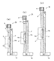
図6に、多機能送りネジ式アリ溝ステージ1の第2の実施例として、精密機器(図示せず)をZ軸方向(略鉛直方向)に移動させる多機能送りネジ式アリ溝ステージ1aを示す。この実施例では、雄ネジ棒7は略鉛直方向に向けられる。そして、第2支持台10が土台固定用締結孔14を有し、ボルト(図示せず)により土台(図示せず)に固定される。また、第1支持台9にはハンドル8が連結される。すなわち、多機能送りネジ式アリ溝ステージ1aの第1支持台9又は第2支持台10を土台固定用締結孔14を有する部品に交換することでZ方向に移動する多機能送りネジ式アリ溝ステージ1aとすることができる。
As a second embodiment of the multi-function feed
図7に、多機能送りネジ式アリ溝ステージ1aの測定距離のバリエーションの例を示す。摺動部品3は、雌ネジ筒6が移動して第1支持台9及び第2支持台10に当接するまで移動する。従って、第1支持台9と第2支持台10とに挟まれた固定部品2の軸方向の長さを変えることで用途に応じた製品が可能となる。また、雄ネジ棒7は、その両端部が第1支持台9及び第2支持台10に両端で支持されているため、その長さが長くなっても良好な性能を発揮できる。
In FIG. 7, the example of the variation of the measurement distance of the multifunction feed screw
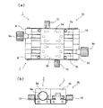
図8に、多機能送りネジ式アリ溝ステージの第3の実施例として、1組の固定部品2及び摺動部品3が摺動方向に沿って連結されて複数組並置される多機能送りネジ式アリ溝ステージ1bを示す。図8(a)は平面図であり、図8(b)はその側面図である。この実施例では、1組の固定部品2a及び摺動部品3aと、1組の固定部品2b及び摺動部品3bとが摺動方向に沿って並置される。この並置された2組は、少なくともハンドル8の位置、雄ネジ棒7の1回転当りの移動量、又は最大移動距離のいずれかが異なる。例えば、図8(a)では、ハンドル8a,8bの位置が反対側に取り付いている。また、雄ネジ棒7a,7bの1回転当りの移動量を相互に異ならせることで、精密機器(図示せず)を固定する摺動部品3a,3bを選択して使用できる。
In FIG. 8, as a third embodiment of the multi-function feed screw dovetail stage, a multi-function feed screw in which a set of fixed
この多機能送りネジ式アリ溝ステージ1の第3の実施例として、1つの固定部品2に対して複数の摺動部品3が摺動方向に沿って並置されても良い。すなわち、上述した1つの固定部品2がベースとなってそれに複数の摺動部品3a,3bが取り付く。
As a third embodiment of the multi-function feed
1,1a,1b 多機能送りネジ式アリ溝ステージ、2,2a,2b,102 固定部品、3,3a,3b,103 摺動部品、4,104 アリ、5,105 アリ溝、6,106 雌ネジ筒、7,7a,7b,107 雄ネジ棒、8,8a,8b,108 ハンドル、9 第1支持台、10 第2支持台、11 ハンドル接続用ボルト、12,112 摺動固定ネジ、13a,13b,113a,113b 目盛板、14 土台固定用締結孔、15 精密機器取付け用孔、16a,16b ハンドル接続用孔、17a,17b 支持台固定ボルト、18 凸状突出部、19 ねじ部、20 丸棒部、21a,21b 雄ネジ棒貫通孔、22 化粧ボルト、23 突出部、24 溝、25 摺動固定ネジ用孔、26 凹状挿入孔、100 送りネジ式アリ溝ステージ、109 ストッパ板、110 ワッシャ。 1, 1a, 1b Multi-function feed screw dovetail stage, 2, 2a, 2b, 102 Fixed part, 3, 3a, 3b, 103 Sliding part, 4,104 dovetail, 5,105 Dovetail groove, 6,106 female Screw cylinder, 7, 7a, 7b, 107 male threaded rod, 8, 8a, 8b, 108 handle, 9 first support base, 10 second support base, 11 handle connection bolt, 12, 112 sliding fixing screw, 13a , 13b, 113a, 113b Scale plate, 14 Fixing hole for fixing base, 15 Hole for attaching precision device, 16a, 16b Hole for connecting handle, 17a, 17b Support fixing bolt, 18 Convex protrusion, 19 Screw part, 20 Round bar part, 21a, 21b Male threaded rod through hole, 22 decorative bolt, 23 projecting part, 24 groove, 25 sliding fixing screw hole, 26 concave insertion hole, 100 feed screw type dovetail Over di-, 109 stopper plate, 110 washers.
Claims (9)
両端部にハンドルと連結する連結部を有する雄ネジ棒と、
固定部品の両側にそれぞれ設けられ、雌ネジ筒の移動方向に関して固定部品の長さを規定し、雄ネジ棒を回転自在に保持する第1の支持台及び第2の支持台と、
連結部を介して雄ネジ棒と着脱自在に連結して雄ネジ棒を回転させるハンドルと、
を備えることを特徴とする多機能送りネジ式アリ溝ステージ。 The sliding part to which the female screw cylinder is connected and the fixed part to which the male screw bar is connected are engaged, and the male screw bar is rotated by the handle operation to move the female screw cylinder to slide the sliding part. In the feed screw type dovetail stage that adjusts the position of the attached precision instrument,
A male threaded rod having a connecting portion for connecting to the handle at both ends;
A first support base and a second support base, which are provided on both sides of the fixed component, respectively, define the length of the fixed component with respect to the moving direction of the female screw cylinder, and rotatably hold the male screw rod;
A handle for detachably connecting to the male threaded rod through the coupling portion and rotating the male threaded rod;
A multi-function feed screw dovetail stage characterized by comprising:
Priority Applications (6)
| Application Number | Priority Date | Filing Date | Title |
|---|---|---|---|
| JP2009173855A JP4512166B1 (en) | 2009-07-27 | 2009-07-27 | Multi-function feed screw dovetail stage |
| DE102010015995.6A DE102010015995B4 (en) | 2009-07-27 | 2010-03-17 | Multi-functional dovetail platform of feed screw type |
| CN201010139201.1A CN101968155B (en) | 2009-07-27 | 2010-03-18 | Multi-functional feed-screw-type dovetail stage |
| TW099108173A TWI480117B (en) | 2009-07-27 | 2010-03-19 | Multi-functional feed-screw-type dovetail stage |
| KR1020100026334A KR101185312B1 (en) | 2009-07-27 | 2010-03-24 | Multi-functional feed-screw-type dovetail stage |
| US12/730,666 US8397600B2 (en) | 2009-07-27 | 2010-03-24 | Multi-functional feed-screw-type dovetail stage |
Applications Claiming Priority (1)
| Application Number | Priority Date | Filing Date | Title |
|---|---|---|---|
| JP2009173855A JP4512166B1 (en) | 2009-07-27 | 2009-07-27 | Multi-function feed screw dovetail stage |
Publications (2)
| Publication Number | Publication Date |
|---|---|
| JP4512166B1 JP4512166B1 (en) | 2010-07-28 |
| JP2011027556A true JP2011027556A (en) | 2011-02-10 |
Family
ID=42582574
Family Applications (1)
| Application Number | Title | Priority Date | Filing Date |
|---|---|---|---|
| JP2009173855A Active JP4512166B1 (en) | 2009-07-27 | 2009-07-27 | Multi-function feed screw dovetail stage |
Country Status (6)
| Country | Link |
|---|---|
| US (1) | US8397600B2 (en) |
| JP (1) | JP4512166B1 (en) |
| KR (1) | KR101185312B1 (en) |
| CN (1) | CN101968155B (en) |
| DE (1) | DE102010015995B4 (en) |
| TW (1) | TWI480117B (en) |
Cited By (3)
| Publication number | Priority date | Publication date | Assignee | Title |
|---|---|---|---|---|
| CN103537808A (en) * | 2012-07-11 | 2014-01-29 | 武汉奔腾楚天激光设备有限公司 | Tool piece and process for assembling Z-axis lead screw of laser cutting machine |
| JP5977468B1 (en) * | 2016-01-29 | 2016-08-24 | 株式会社ミラック光学 | Dovetail-type workpiece clamping device and dovetail-type workpiece clamping method |
| JP2017127921A (en) * | 2016-01-20 | 2017-07-27 | 株式会社ミラック光学 | Dovetail groove type work-piece grasping device and dovetail groove sliding stage with dovetail groove type work-piece grasping device |
Families Citing this family (20)
| Publication number | Priority date | Publication date | Assignee | Title |
|---|---|---|---|---|
| CN102528512A (en) * | 2010-12-10 | 2012-07-04 | 张勇毅 | Linear regulating assembly |
| JP4767367B1 (en) * | 2011-02-28 | 2011-09-07 | 株式会社ミラック光学 | Feed screw dovetail stage |
| JP4830053B1 (en) * | 2011-05-02 | 2011-12-07 | 株式会社ミラック光学 | Slide operation dovetail slide stage |
| CN102506714B (en) * | 2011-10-10 | 2013-12-04 | 上海应用技术学院 | Laser displacement transducer mounting support provided with adjusting and self-calibrating structure |
| WO2014054188A1 (en) * | 2012-10-05 | 2014-04-10 | 株式会社ミラック光学 | Motorized units for manual stages, and manual stages with motorized units |
| TWI494596B (en) * | 2013-08-21 | 2015-08-01 | Miruc Optical Co Ltd | Portable terminal adapter for microscope and microscope shooting method using portable terminal adapter |
| CN103801975B (en) * | 2014-02-18 | 2016-08-31 | 宁波恒瑞机械有限公司 | A displacement positioning structure |
| US10012689B2 (en) * | 2015-03-25 | 2018-07-03 | Applied Materials Israel Ltd. | Method of inspecting a specimen and system thereof |
| CN104816119B (en) * | 2015-04-30 | 2017-01-04 | 广州明珞汽车装备有限公司 | A kind of orthoscopic flexible positioning device |
| TWI610066B (en) * | 2016-07-12 | 2018-01-01 | Oto Photonics Inc. | Spectrometer and manufacturing method thereof |
| CN108098170B (en) * | 2016-09-22 | 2019-10-18 | 广西盛隆冶金有限公司 | A kind of localization method of the steel disc fixture applied to laser cutting |
| CN107725978A (en) * | 2017-10-17 | 2018-02-23 | 董杰 | A kind of removable industrial machinery base |
| CN109373134A (en) * | 2018-09-19 | 2019-02-22 | 合肥市航嘉电子技术有限公司 | A camera three-dimensional position adjustment device |
| CN109668021B (en) * | 2018-12-14 | 2020-09-11 | 河北工程大学 | A binocular vision precision adjustment bracket |
| CN112643627A (en) * | 2020-12-14 | 2021-04-13 | 李波 | Part machining operation platform for machining |
| CN113757502A (en) * | 2021-08-18 | 2021-12-07 | 湖北省高路机电工程有限公司 | Power supply maintenance device convenient to adjust and use for electromechanical equipment |
| EP4414109A4 (en) * | 2021-09-24 | 2025-06-25 | Cosmo Koki Co., Ltd. | DRILLING MACHINE |
| CN113829109A (en) * | 2021-10-09 | 2021-12-24 | 威日德精机(广东)有限公司 | A Z-axis motion system applied to gantry structure |
| JP7407165B2 (en) * | 2021-12-23 | 2023-12-28 | Thk株式会社 | Feeding mechanism and its manufacturing method |
| KR20250146424A (en) | 2024-04-01 | 2025-10-13 | (주)멘토티앤씨 | Dovetail stage using a belt |
Citations (7)
| Publication number | Priority date | Publication date | Assignee | Title |
|---|---|---|---|---|
| JPS5633259A (en) * | 1979-08-29 | 1981-04-03 | Mutoh Ind Ltd | Encoder for machine tool |
| JPH0372147U (en) * | 1989-11-16 | 1991-07-22 | ||
| JPH04136705A (en) * | 1990-09-28 | 1992-05-11 | Hitachi Denshi Ltd | Positioning stage |
| JPH06645U (en) * | 1992-06-09 | 1994-01-11 | 東芝機械株式会社 | Different pitch conveyor |
| JPH063929U (en) * | 1991-02-26 | 1994-01-18 | バンドー化学株式会社 | Feed screw exchange mechanism |
| JP2000220715A (en) * | 1999-01-29 | 2000-08-08 | Oriental Motor Co Ltd | Linear actuator |
| JP4267054B1 (en) * | 2008-07-14 | 2009-05-27 | 株式会社ミラック光学 | Compound dovetail slide stage |
Family Cites Families (15)
| Publication number | Priority date | Publication date | Assignee | Title |
|---|---|---|---|---|
| US2323010A (en) * | 1940-01-29 | 1943-06-29 | Oscar Christianson | Machine tool attachment |
| US2755682A (en) * | 1953-10-09 | 1956-07-24 | Charles J Boyd | Adjusting mechanism |
| US2910779A (en) * | 1957-09-20 | 1959-11-03 | John F Patton | Vernier height and depth gauge |
| US3067521A (en) * | 1961-01-23 | 1962-12-11 | Ii Robert E Platt | Vernier gauging device |
| US3221841A (en) * | 1964-01-27 | 1965-12-07 | Advance Prod Corp | Cam operated, axially movable brake |
| CH688357A5 (en) * | 1994-02-16 | 1997-08-15 | Haemmerli Jagd Und Sportwaffenf | Diopter for a sporting rifle. |
| CH688786A5 (en) * | 1994-10-18 | 1998-03-13 | Fernand Moser | Handwheel or handcrank for fixing on rotary shaft e.g. for machine tool to cylindrical sleeve and compression ring for clamping handwheel or handcrank |
| DE29700712U1 (en) * | 1997-01-16 | 1997-02-27 | RK Rose + Krieger GmbH & Co. KG Verbindungs- und Positioniersysteme, 32423 Minden | Spindle drive |
| DE19804238B9 (en) * | 1998-02-04 | 2006-01-12 | Hans Roßner & Sohn GmbH | positioning |
| JP4526890B2 (en) | 2004-07-08 | 2010-08-18 | シグマ光機株式会社 | Rotating stage |
| DE102006027523A1 (en) * | 2006-06-14 | 2008-01-10 | Rk Rose + Krieger Gmbh Verbindungs- Und Positioniersysteme | linear unit |
| CN200977527Y (en) * | 2006-07-14 | 2007-11-21 | 李传斌 | Wedge lateral rolling mold dismounting-free repair knife tool |
| JP5549061B2 (en) | 2007-12-27 | 2014-07-16 | ダイソー株式会社 | Thermosetting resin composition |
| CN101241059B (en) * | 2008-03-20 | 2010-09-01 | 北京城建建设工程有限公司 | Steel cold bending test machine |
| CN100581715C (en) * | 2008-12-01 | 2010-01-20 | 山西省电力公司电力科学研究院 | Repair equipment for generator rotor journal |
-
2009
- 2009-07-27 JP JP2009173855A patent/JP4512166B1/en active Active
-
2010
- 2010-03-17 DE DE102010015995.6A patent/DE102010015995B4/en active Active
- 2010-03-18 CN CN201010139201.1A patent/CN101968155B/en active Active
- 2010-03-19 TW TW099108173A patent/TWI480117B/en active
- 2010-03-24 US US12/730,666 patent/US8397600B2/en active Active
- 2010-03-24 KR KR1020100026334A patent/KR101185312B1/en active Active
Patent Citations (7)
| Publication number | Priority date | Publication date | Assignee | Title |
|---|---|---|---|---|
| JPS5633259A (en) * | 1979-08-29 | 1981-04-03 | Mutoh Ind Ltd | Encoder for machine tool |
| JPH0372147U (en) * | 1989-11-16 | 1991-07-22 | ||
| JPH04136705A (en) * | 1990-09-28 | 1992-05-11 | Hitachi Denshi Ltd | Positioning stage |
| JPH063929U (en) * | 1991-02-26 | 1994-01-18 | バンドー化学株式会社 | Feed screw exchange mechanism |
| JPH06645U (en) * | 1992-06-09 | 1994-01-11 | 東芝機械株式会社 | Different pitch conveyor |
| JP2000220715A (en) * | 1999-01-29 | 2000-08-08 | Oriental Motor Co Ltd | Linear actuator |
| JP4267054B1 (en) * | 2008-07-14 | 2009-05-27 | 株式会社ミラック光学 | Compound dovetail slide stage |
Cited By (3)
| Publication number | Priority date | Publication date | Assignee | Title |
|---|---|---|---|---|
| CN103537808A (en) * | 2012-07-11 | 2014-01-29 | 武汉奔腾楚天激光设备有限公司 | Tool piece and process for assembling Z-axis lead screw of laser cutting machine |
| JP2017127921A (en) * | 2016-01-20 | 2017-07-27 | 株式会社ミラック光学 | Dovetail groove type work-piece grasping device and dovetail groove sliding stage with dovetail groove type work-piece grasping device |
| JP5977468B1 (en) * | 2016-01-29 | 2016-08-24 | 株式会社ミラック光学 | Dovetail-type workpiece clamping device and dovetail-type workpiece clamping method |
Also Published As
| Publication number | Publication date |
|---|---|
| TW201103686A (en) | 2011-02-01 |
| DE102010015995B4 (en) | 2016-09-15 |
| CN101968155A (en) | 2011-02-09 |
| US20110017009A1 (en) | 2011-01-27 |
| KR20110011514A (en) | 2011-02-08 |
| JP4512166B1 (en) | 2010-07-28 |
| DE102010015995A1 (en) | 2011-02-17 |
| CN101968155B (en) | 2015-06-24 |
| TWI480117B (en) | 2015-04-11 |
| US8397600B2 (en) | 2013-03-19 |
| KR101185312B1 (en) | 2012-09-21 |
Similar Documents
| Publication | Publication Date | Title |
|---|---|---|
| JP4512166B1 (en) | Multi-function feed screw dovetail stage | |
| JP4073919B2 (en) | An aerial positioning stand with a combined articulated arm and flexible tube arm structure | |
| JP4505535B1 (en) | Manual stage | |
| JP4606501B2 (en) | Manual stage | |
| KR101483031B1 (en) | Slide operation-type dovetail groove sliding stage | |
| CN102689284A (en) | A rack extension jig device | |
| CN104793313B (en) | A Transmission Mechanism Applied to Optical Zoom Lens | |
| JP4267054B1 (en) | Compound dovetail slide stage | |
| JP4500879B1 (en) | Manual stage with tilting function and tilting stage | |
| JP4767367B1 (en) | Feed screw dovetail stage | |
| JP6785537B2 (en) | Tuners for microscope lighting components, microscope illuminators and microscopes | |
| HK1148804A (en) | Multi-functional feed-screw-type dovetail stage | |
| JP2011076032A (en) | Shaft fixing type sliding stage | |
| JP2014215378A (en) | Back focus adjustment mechanism | |
| JP4574716B2 (en) | Manual stage configuration system | |
| JP5388624B2 (en) | Lens barrel and optical apparatus having the same | |
| JP5965085B1 (en) | Dovetail-type workpiece gripping device and dovetail-sliding stage with dovetail-type workpiece gripping device | |
| JP2009244719A (en) | Optical device and imaging apparatus | |
| JP2007298864A (en) | Imaging lens with optical axis shift adjustment mechanism | |
| US20070047107A1 (en) | Lens feed mechanism | |
| JP2005234462A (en) | Microscope system | |
| JP5124543B2 (en) | Optical system for synthesizing first and second partial image beams respectively traveling from a sample into one composite image beam | |
| JP2009282145A (en) | Zoom magnification detecting unit and zoom microscope having the same | |
| JP5570804B2 (en) | microscope | |
| JP2000275001A (en) | Female thread effective diameter measuring instrument |
Legal Events
| Date | Code | Title | Description |
|---|---|---|---|
| TRDD | Decision of grant or rejection written | ||
| A01 | Written decision to grant a patent or to grant a registration (utility model) |
Free format text: JAPANESE INTERMEDIATE CODE: A01 Effective date: 20100427 |
|
| A01 | Written decision to grant a patent or to grant a registration (utility model) |
Free format text: JAPANESE INTERMEDIATE CODE: A01 |
|
| A61 | First payment of annual fees (during grant procedure) |
Free format text: JAPANESE INTERMEDIATE CODE: A61 Effective date: 20100507 |
|
| FPAY | Renewal fee payment (event date is renewal date of database) |
Free format text: PAYMENT UNTIL: 20200514 Year of fee payment: 10 |
|
| R150 | Certificate of patent or registration of utility model |
Ref document number: 4512166 Country of ref document: JP Free format text: JAPANESE INTERMEDIATE CODE: R150 Free format text: JAPANESE INTERMEDIATE CODE: R150 |
|
| R250 | Receipt of annual fees |
Free format text: JAPANESE INTERMEDIATE CODE: R250 |
|
| R250 | Receipt of annual fees |
Free format text: JAPANESE INTERMEDIATE CODE: R250 |