JP2011005703A - Ink jet recording apparatus and ink jet recording method - Google Patents
Ink jet recording apparatus and ink jet recording method Download PDFInfo
- Publication number
- JP2011005703A JP2011005703A JP2009150075A JP2009150075A JP2011005703A JP 2011005703 A JP2011005703 A JP 2011005703A JP 2009150075 A JP2009150075 A JP 2009150075A JP 2009150075 A JP2009150075 A JP 2009150075A JP 2011005703 A JP2011005703 A JP 2011005703A
- Authority
- JP
- Japan
- Prior art keywords
- recording
- mask pattern
- region
- nozzle row
- nozzles
- Prior art date
- Legal status (The legal status is an assumption and is not a legal conclusion. Google has not performed a legal analysis and makes no representation as to the accuracy of the status listed.)
- Pending
Links
Images


Classifications
-
- B—PERFORMING OPERATIONS; TRANSPORTING
- B41—PRINTING; LINING MACHINES; TYPEWRITERS; STAMPS
- B41J—TYPEWRITERS; SELECTIVE PRINTING MECHANISMS, i.e. MECHANISMS PRINTING OTHERWISE THAN FROM A FORME; CORRECTION OF TYPOGRAPHICAL ERRORS
- B41J2/00—Typewriters or selective printing mechanisms characterised by the printing or marking process for which they are designed
- B41J2/005—Typewriters or selective printing mechanisms characterised by the printing or marking process for which they are designed characterised by bringing liquid or particles selectively into contact with a printing material
- B41J2/01—Ink jet
- B41J2/21—Ink jet for multi-colour printing
- B41J2/2132—Print quality control characterised by dot disposition, e.g. for reducing white stripes or banding
Abstract
Description
本発明はインクを吐出するノズルを高密度に配列してなるノズル列を有するインクジェット記録ヘッドを用いて、記録媒体上に画像を記録するインクジェット記録方法およびインクジェット記録装置に関する。 The present invention relates to an ink jet recording method and an ink jet recording apparatus for recording an image on a recording medium using an ink jet recording head having a nozzle row in which nozzles for discharging ink are arranged at high density.
コンピュータやワードプロセッサ等の情報処理機器および通信機器の普及に伴い、それらの機器で処理されたデジタル画像情報を出力する出力装置の需要が高まっている。このような出力装置の一つとして、インク滴を吐出して記録媒体上にドットを形成することにより画像を形成するインクジェット記録装置が急速に普及している。このインクジェット記録装置は、記録速度および記録画像の解像度の向上を図るため、インク滴を吐出するインク吐出口、液路、および記録素子等からなる吐出部(以下、ノズルともいう)を多数個、集積・配列した記録ヘッドを用いる。また、近年ではカラーの記録画像を出力可能とする要求が高まっている。特に写真画像の出力においては高画質化のためインク滴の体積をより小さくすることが望まれている。 With the spread of information processing devices such as computers and word processors and communication devices, there is an increasing demand for output devices that output digital image information processed by these devices. As one of such output devices, an ink jet recording apparatus that forms an image by ejecting ink droplets to form dots on a recording medium is rapidly spreading. In order to improve the recording speed and the resolution of a recorded image, this ink jet recording apparatus has a large number of ejection portions (hereinafter also referred to as nozzles) composed of ink ejection ports for ejecting ink droplets, liquid paths, and recording elements, An integrated and arranged recording head is used. In recent years, there has been an increasing demand to be able to output color recording images. Particularly in the output of photographic images, it is desired to make the volume of ink droplets smaller in order to improve image quality.
一方、近年のノズルの集積配列化の技術進歩を背景に、高密度かつ長尺な所謂長尺記録ヘッドの製作が可能になりつつある。この長尺記録ヘッドは、記録媒体に対する一回の記録走査によって記録媒体上に記録できる領域の幅を、従来の記録ヘッドよりも拡大している。このため、従来と同様に高い画像品質を維持しつつ、今までにない高速記録を実現できる極めて有用な技術として、さらなる技術開発が進められている。インクジェット記録装置では一般的に、記録時に記録ヘッドと記録媒体との間に気流が生じることは従来から知られている。そして、このような長尺記録ヘッドを用いて記録動作を行うインクジェット記録装置では、記録時に記録ヘッドと記録媒体との間で、高密度な吐出インクの壁を迂回するように気流が生じる。この迂回気流によってインク滴の吐出方向が変化し着弾位置ズレが生じる事がある。このような画像品質の低下を防ぐ方法として、特許文献1に開示された技術が知られている。
On the other hand, against the background of recent technological advances in nozzle integration, it is becoming possible to manufacture so-called long recording heads of high density and length. In this long recording head, the width of the area that can be recorded on the recording medium by one recording scanning with respect to the recording medium is larger than that of the conventional recording head. For this reason, further technical development has been promoted as an extremely useful technique capable of realizing unprecedented high-speed recording while maintaining high image quality as in the past. In an ink jet recording apparatus, it is conventionally known that an air flow is generally generated between a recording head and a recording medium during recording. In an ink jet recording apparatus that performs a recording operation using such a long recording head, an air flow is generated between the recording head and the recording medium so as to bypass the wall of the high-density ejected ink during recording. This detour air flow may change the ejection direction of the ink droplets and cause landing position deviation. As a method for preventing such a decrease in image quality, a technique disclosed in
図8は、従来の記録装置におけるマスクパターンを示した図である。マスクパターン100は各記録領域を2回の走査で補完しながら完成させていく所謂2パス記録方式に適合するマスクの一例である。このマスクパターン100を用いた従来の記録方法では、記録領域をノズル配列方向(図8矢印α方向)に沿って所定間隔で2領域に分割する。一方の領域では、2パス記録における1回目の記録で高記録領域Hnの記録を行い、2回目の記録では、記録を間引いた低記録領域Lnの記録を行う。他方の領域では、1回目の記録で低記録領域Lnの記録を行い、2回目の記録では高記録領域Hnの記録を行う。そして、これらを合わせて100%の記録率を達成する。このように、ノズル配列方向(図8矢印α方向)の間引き率が低、高、低、高のように交互に配されたマスクパターン100を用いると、高密度な吐出インクの壁に隙間が生じる。具体的には、マスクパターンの高間引き率領域に対応する箇所が隙間となることから、吐出インクの壁にはノズル列方向に交互の隙間が生じる。すると、この隙間から気流が抜け、その分、迂回する気流の量が減り、結果的にこの迂回気流による着弾位置ズレも抑制される。
FIG. 8 is a diagram showing a mask pattern in a conventional recording apparatus. The
しかし特許文献1に記載の技術では、ノズル列方向における吐出インクの壁に気流が抜けるのに十分な隙間を形成しなければならない。この方法では、2つの領域で高記録領域Hnおよび低記録領域Lnの記録を行う記録ヘッドの走査方向が異なる。このように高記録領域および低記録領域の記録を行う走査の方向が領域ごとに異なる場合、濃度ムラが記録画像に現れることがあった。例えば、吐出したインクの主滴と、主滴の後方で飛翔する極少量インク滴であるサテライトドットと、の間隔が往方向と復方向とで異なりドット面積率が変動する場合、往方向と復方向とで画像濃度差が発生する。そしてこの画像濃度差は濃度ムラとして認識されることがあった。
However, in the technique described in
よって本発明は、記録ヘッドと記録媒体との間に発生する乱流を抑制し、マスクパターンに起因する濃度ムラを抑制することが可能なインクジェット記録装置およびインクジェット記録方法を提供することを目的とする。 Accordingly, an object of the present invention is to provide an ink jet recording apparatus and an ink jet recording method capable of suppressing turbulent flow generated between a recording head and a recording medium and suppressing density unevenness caused by a mask pattern. To do.
そのため、本発明のインクジェット記録装置は、同じ色のインクを吐出する複数のノズルが同一ピッチで配列された、第1ノズル列と第2ノズル列と、を含み、前記第1ノズル列と、前記第2ノズル列とは、互いにノズル配列方向に隣接するノズルのピッチの半ピッチずれて配置された前記記録ヘッドを、記録媒体に対して相対的に移動させつつ前記ノズルからインクを吐出することで、前記記録媒体に画像を記録するインクジェット記録装置であって、前記記録媒体の同一の記録領域に対して前記記録ヘッドを相対的に複数回移動させる移動手段と、前記同一の記録領域に対する複数回の移動それぞれに対応する異なるマスクパターンを用い、前記同一の記録領域に対応する2値の画像データを間引く間引き手段と、前記複数回の移動それぞれにおいて、前記間引き手段により間引かれた2値の画像データに基づいて前記同一の記録領域に間引き画像を記録することにより、前記同一の記録領域の記録を完成させる記録制御手段と、を備え、前記第1ノズル列には、相対的に高い記録率により記録が行われる複数のノズルと相対的に低い記録率により記録が行われる複数のノズルとが交互に配置されており、前記第1ノズル列の相対的に高い記録率で記録を行う隣接した前記ノズル同士の間を前記第2ノズル列の相対的に低い記録率で記録を行う前記ノズルが補完し、前記第1ノズル列の相対的に低い記録率で記録を行う隣接した前記ノズル同士の間を前記第2ノズル列の相対的に高い記録率で記録を行う前記ノズルが補完することを特徴とする。 Therefore, the inkjet recording apparatus of the present invention includes a first nozzle row and a second nozzle row in which a plurality of nozzles that eject ink of the same color are arranged at the same pitch, and the first nozzle row, The second nozzle row refers to ejecting ink from the nozzles while moving the recording heads arranged with a half-pitch shift of the pitch of nozzles adjacent to each other in the nozzle arrangement direction relative to the recording medium. An inkjet recording apparatus for recording an image on the recording medium, the moving unit moving the recording head relative to the same recording area of the recording medium a plurality of times; and a plurality of times for the same recording area. Thinning means for thinning out binary image data corresponding to the same recording area using different mask patterns corresponding to the respective movements, and the plurality of movements And recording control means for completing the recording in the same recording area by recording the thinned image in the same recording area based on the binary image data thinned out by the thinning means. In the first nozzle row, a plurality of nozzles that perform recording at a relatively high recording rate and a plurality of nozzles that perform recording at a relatively low recording rate are alternately arranged. The nozzles that perform recording at a relatively low recording rate of the second nozzle row complement each other between the adjacent nozzles that perform recording at a relatively high recording rate of the nozzle row, and the relative relationship of the first nozzle row The nozzles that perform recording at a relatively high recording rate of the second nozzle array complement each other between the adjacent nozzles that perform recording at an extremely low recording rate.
また、本発明のインクジェット記録方法は、同じ色のインクを吐出する複数のノズルが所定の間隔で配列された第1ノズル列と第2ノズル列とが前記複数のノズルの配列方向に前記所定の間隔の半分の間隔でずれて配置された前記記録ヘッドを、記録媒体の同一の記録領域に対して複数回相対移動させつつ前記ノズルからインクを吐出することにより、前記記録媒体に画像を記録するインクジェット記録方法であって、前記第1ノズル列に対応する第1マスクパターンと前記第2ノズル列に対応する第2マスクパターンとを用い、前記第1ノズル列と第2ノズル列とにより記録すべき、前記同一の記録領域に対応する画像データを前記複数回の相対移動に分割する分割工程と、前記複数回の移動それぞれにおいて、前記分割工程により分割された画像データに基づいて前記第1ノズル列と第2ノズル列とに画像を記録させる記録制御工程と、を備え、前記第1マスクパターンと前記第2マスクパターンとに、相対的に低い記録率の第1領域と相対的に高い記録率の第2領域とを前記ノズルの配列方向に対応する方向に交互に備える工程と、前記第1マスクパターンの第1領域と前記第2マスクパターンの第2領域とを、前記対応する方向に同じ位置に設け、前記第1マスクパターンの第2領域と前記第2マスクパターンの第1領域とを、前記対応する方向に同じ位置に設けることを特徴とする。 In the inkjet recording method of the present invention, the first nozzle row and the second nozzle row in which a plurality of nozzles that eject ink of the same color are arranged at a predetermined interval are arranged in the arrangement direction of the plurality of nozzles. An image is recorded on the recording medium by ejecting ink from the nozzles while moving the recording heads, which are shifted at half the interval, relative to the same recording area of the recording medium a plurality of times. In the ink jet recording method, a first mask pattern corresponding to the first nozzle array and a second mask pattern corresponding to the second nozzle array are used, and recording is performed by the first nozzle array and the second nozzle array. In the dividing step of dividing the image data corresponding to the same recording area into the plurality of relative movements, and in each of the plurality of movements, the image data is divided by the dividing step. A recording control step of recording an image on the first nozzle row and the second nozzle row based on the obtained image data, and a relatively low recording rate for the first mask pattern and the second mask pattern. The first region of the first mask pattern and the second region of the relatively high recording rate alternately in a direction corresponding to the arrangement direction of the nozzles, and the first region of the first mask pattern and the second region of the second mask pattern Two regions are provided at the same position in the corresponding direction, and the second region of the first mask pattern and the first region of the second mask pattern are provided at the same position in the corresponding direction. To do.
本発明によればインクジェット記録装置は、記録媒体の同一の記録領域に対して記録ヘッドを相対的に複数回移動させる移動手段を備える。またインクジェット記録装置は、同一の記録領域に対する複数回の移動それぞれに対応する異なるマスクパターンを用い、同一の記録領域に対応する2値の画像データを間引く間引き手段を備える。さらにインクジェット記録装置は、複数回の移動それぞれにおいて、間引き手段により間引かれた2値の画像データに基づいて同一の記録領域に間引き画像を記録することにより、同一の記録領域の記録を完成させる記録制御手段を備える。そして、第1ノズル列には、相対的に高い記録率により記録が行われる複数のノズルと相対的に低い記録率により記録が行われる複数のノズルとを交互に配置する。また、第1ノズル列の相対的に高い記録率で記録を行う隣接したノズル同士の間を第2ノズル列の相対的に低い記録率で記録を行うノズルが補完する。さらに、第1ノズル列の相対的に低い記録率で記録を行う隣接したノズル同士の間を第2ノズル列の相対的に高い記録率で記録を行うノズルが補完する。これによって、記録ヘッドと記録媒体との間に発生する乱流を抑制し、マスクパターンに起因する濃度ムラを抑制することが可能なインクジェット記録装置およびインクジェット記録方法を実現することができた。 According to the present invention, the ink jet recording apparatus includes moving means for relatively moving the recording head a plurality of times with respect to the same recording area of the recording medium. In addition, the ink jet recording apparatus includes thinning means that thins out binary image data corresponding to the same recording area using different mask patterns corresponding to each of a plurality of movements with respect to the same recording area. Further, the ink jet recording apparatus completes the recording of the same recording area by recording the thinned image in the same recording area based on the binary image data thinned out by the thinning means in each of the plurality of movements. A recording control means is provided. In the first nozzle row, a plurality of nozzles that perform recording at a relatively high recording rate and a plurality of nozzles that perform recording at a relatively low recording rate are alternately arranged. In addition, the nozzles that perform recording at a relatively low recording rate in the second nozzle array complement each other between adjacent nozzles that perform recording at a relatively high recording rate in the first nozzle array. Further, the nozzles that perform recording at a relatively high recording rate in the second nozzle array complement each other between adjacent nozzles that perform recording at a relatively low recording rate in the first nozzle array. Thus, an ink jet recording apparatus and an ink jet recording method capable of suppressing turbulent flow generated between the recording head and the recording medium and suppressing density unevenness due to the mask pattern can be realized.
以下、図面を参照して本発明の第1の実施の形態について説明する。
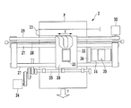
図1は、本発明の実施形態に適用可能なシリアル型インクジェット記録装置の概略構成を示した正面図である。キャリッジ32は、ガイドシャフト27およびリニアエンコーダ28によって主走査方向(矢印X方向)に沿って往復移動可能に支持されている。このキャリッジ32は、キャリッジモータ30を駆動して駆動ベルト29を移動させることにより、ガイドシャフト27に沿って往復移動する。また、キャリッジ32には、インクジェット記録ヘッド(以下、単に記録ヘッドともいう)21が着脱可能に搭載されている。記録ヘッド21には、インクを吐出するための吐出部(以下、ノズルともいう)が主走査方向に沿って複数配列されている。この記録ヘッド21の各ノズルの内に形成される液路には、液路内のインクを吐出させるための熱エネルギを発生する発熱素子(以下、ヒータともいう)が設けられている。また、このシリアル型インクジェット記録装置には、普通紙や高品位専用紙、OHPシート、光沢紙、光沢フィルム、ハガキ等の記録媒体Pを搬送する搬送機構が設けられている。この搬送機構は、不図示の搬送ローラと、排紙ローラ25および、搬送モータ26などを有し、搬送モータ26の駆動に伴い副走査方向(矢印Y方向)に間欠的に搬送される。また、記録ヘッド21および搬送機構には、後述のコントローラ部から送出される吐出信号および制御信号がフレキシブルケーブル23を介して送られ、その吐出信号および制御信号などに応じて各記録ヘッド21および搬送機構が動作する。すなわち、記録ヘッド21の発熱素子は、リニアエンコーダ28から出力されるキャリッジ32の位置信号と、吐出信号とに基づいて駆動され、駆動時に発生する熱エネルギによってインク滴をノズルから吐出させて記録媒体上に着弾させる。また搬送機構は、制御信号に基づき、記録ヘッド21の主走査と主走査との間において記録媒体Pを副走査方向へと一定量搬送する。この記録ヘッド21による記録動作と搬送機構による搬送動作とによって記録ヘッド21と記録媒体Pとを相対的に動かす動作を繰り返すことにより、記録媒体P全体に画像が形成される。また、記録領域外に設定されたキャリッジ32のホームポジションには、記録ヘッド21に形成される吐出口の密閉、開放を可能とするキャップ部35を備えた回復ユニット34が設置されている。
The first embodiment of the present invention will be described below with reference to the drawings.
FIG. 1 is a front view showing a schematic configuration of a serial type ink jet recording apparatus applicable to an embodiment of the present invention. The
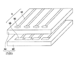
図2は、記録ヘッド21の吐出部(ノズル)近傍の構造を示した斜視図である。記録ヘッド21は、インクを加熱するための複数のヒータnbが形成された基板であるヒータボードndと、このヒータボードndの上にかぶせられる天板neとを備えている。天板neには、複数の吐出口naが形成されており、吐出口naの後方には、この吐出口naに連通するトンネル状の液路ncが形成されている。各液路ncは、その後方において1つのインク液室に共通に接続されており、インク液室にはインク供給口を介してインクが供給され、このインクはインク液室からそれぞれの液路ncに供給される。ヒータボードndと天板neとは、各液路ncに各ヒータnbが対応するように位置決めされて接合される。図2においては、4つのヒータnbしか示されていないが、実際の記録装置にはさらに多くのヒータndが設けられており、夫々の液路ncに対応して1つずつのヒータndが配置されている。このヒータnbに所定の駆動パルスを供給すると、ヒータnb上のインクが沸騰して気泡を形成し、この気泡の体積膨張により液路nc内のインクが吐出口naから液滴となって吐出される。このように、ノズルnは、吐出口naと、ヒータnbと、液路ncとにより構成されている。なお、本発明に適用可能なインクジェット記録方式は、図2に示したような発熱素子を使用した方式に限定されるものではない。例えば、インク滴を連続噴射し粒子化するコンティニュアス型のインクジェット方式であれば、荷電制御型、発散制御型等が適用可能である。また、必要に応じてインク滴を吐出するオンデマンド型のインクジェット記録方式であれば、ピエゾ振動素子の機械的振動により吐出口からインク滴を吐出する圧力制御方式等が適用可能である。
FIG. 2 is a perspective view showing a structure in the vicinity of the ejection portion (nozzle) of the
図3は、本実施形態におけるインクジェット記録装置の制御系の一構成例を示すブロック図である。データ入力部71は、ホストコンピュータなどをはじめとする外部機器80から送信される画像データおよび制御データなどを受信する。操作部72はデータ入力あるいは設定操作などを行う。また、CPU73は各種の情報処理および制御動作(記録制御)を行い、記憶媒体74は各種データを記憶する。この記憶媒体74には、記録媒体Pの種類に関する情報、インクに関する情報、記録時の温度、湿度等の環境に関する情報などの画像記録情報、を格納する記録情報格納部74a、および各種制御プログラム群を格納するプログラム格納部74bが設けられている。さらに、RAM75はCPU72の処理データや入力データなどを一時的に格納しており、画像データ処理部76は入力された画像データに対して色変換、二値化処理などを含む所定の画像処理を行う。また、画像記録部77は記録ヘッドや搬送機構などによって画像出力を実行し、バスライン78は本装置内のアドレス信号、データ、制御信号などを伝送する。より具体的に説明すると、外部機器80としては、例えば、スキャナやデジタルカメラなどの画像入力機器、あるいはパーソナルコンピュータなどがある。このスキャナやデジタルカメラ等から出力される多値画像データ(例えば、RGBの8bitデータ)やパーソナルコンピュータのハードディスク等に保存されている多値画像データは画像データ入力部71に入力される。また、操作部72は各種パラメータの設定および記録開始指示の入力などを行うための各種キーが備えられている。CPU73は記憶媒体中の各種プログラムに従ってインクジェット記録装置全体の制御を行う。記憶媒体74に格納されるプログラムとしては、制御プログラムやエラー処理プログラムに従ってインクジェット記録装置を動作させるためのプログラムがあり、本実施形態の動作は全てこのプログラムに従って実行される。また、このプログラムを格納する記憶媒体74としては、ROM、FD、CD−ROM、HD、メモリカード、光磁気ディスクなどが使用可能である。RAM75は、記憶媒体74に格納される各種プログラムを実行する際のワークエリア、エラー処理時の一時待避エリア及び画像処理時のワークエリアとして用いられる。また、RAM75では、記憶媒体74の中の各種テーブルをコピーした後、そのテーブルの内容を変更し、この変更したテーブルを参照しながら画像処理を進めることも可能である。画像処理部76は、入力された多値画像データ(例えば、8bitのRGBデータ)を画素毎に各インク色の多値データ(例えば、8bitのCMYBkデータ)に変換する色分解処理を行う。さらに、その各色の多値データをK値(例えば、17値)のデータに各画素毎に量子化し、その量子化された各画素が示す階調値“K”(階調値0〜16)に対応するドット配置パターンを設定する処理を行う。なお、ここではK値化処理には多値誤差拡散法を用いているが、これに限定されるものではなく、平均濃度保存法、ディザマトリックス法等、任意の中間調処理方法などを用いることも可能である。また、K値化処理を行った後は、それぞれの階調階調値に応じて単位領域毎にドット配置パターンに対応させるドット配置パターン化処理を行う。そして、記録ヘッドによる複数回の記録走査において、ドット配置パターン化処理によって生成された2値の記録データに対し、間引きマスクパターンにより各記録走査に記録データを分配する間引き処理を行う。なお、記録ヘッドによる複数回の記録走査には、2列以上のノズル列を有する記録ヘッドによって行われる1回の記録走査も含まれる。これら処理を繰り返すことにより、記録ヘッド21の各ノズルに対する吐出、不吐出を表す2値の記録データが作成される。そして、画像記録部77は、画像データ処理部76で作成された2値の記録データに基づいてインクを吐出し、記録媒体P上にドット画像を形成する。
FIG. 3 is a block diagram illustrating a configuration example of a control system of the ink jet recording apparatus according to the present embodiment. The
図4は、ノズル列を複数列備えた本実施形態の記録ヘッド21を吐出口面側から観察した場合の平面図である。本実施形態の記録ヘッド21には、インクを吐出するノズルが複数配列されてなるノズル列が、複数色分(ここでは4色分)主走査方向に6ブロックに分けて配列されている。ブロックC1およびブロックC2は、同色のシアンインクを、ブロックM1およびブロックM2は同色のマゼンタインクを、ブロックYはイエローインクを、ブロックBkはブラックインクを吐出するノズル列をそれぞれ示している。各ノズル列において、個々のノズルは各色とも同一ピッチである1/600インチのピッチで副走査方向に256個ずつ配列されており、副走査方向には約10.8mmの記録幅の画像を記録することが出来る。ブロックBkおよびブロックYのノズル列は600dpiのピッチで配列する吐出口列を2列有しており、各ノズル列の吐出口は副走査方向に互いに隣接ノズル間隔の半ピッチだけずれている。ブロックBkおよびブロックYの一対のノズル列に含まれる各吐出口からは、約5.5plのインク滴が吐出される。また、ブロックC1、C2、およびブロックM1、M2は、各ブロックに約5.5plのインク滴量を吐出するノズル列、約2.5plのインク滴量を吐出するノズル列、さらに、約1.5plのインク滴量を吐出するノズル列を有している。ブロックC1、C2、およびブロックM1、M2に含まれる同じ液滴量を吐出するノズル列は、ブロック間で一対のノズル列を構成し、互いの吐出口が副走査方向に隣接ノズル間隔の半ピッチずれた関係で配置されている。つまり、ブロックC1の隣接するノズル同士の間をブロックC2のノズルによって補完可能になっている。このように、各ブロックC1、C2、およびブロックM1、M2に配列された一対のノズル列の各々を、第1ノズル列、第2ノズル列と表す。なお、図4において、記録ヘッド21がキャリッジ32に装着された状態で、複数のノズルの配列方向(矢印α方向)は、記録媒体Pの搬送方向である副走査方向(Y方向)と一致する。従って、記録ヘッド21の走査方向は、この副走査方向と直交するX方向になる。
FIG. 4 is a plan view when the
次に、本発明の特徴的部分である間引き分割記録の実施形態について説明する。本実施形態では、所定の幅を持つ低記録率領域(高間引き率領域)と高記録率領域(低間引き率領域)とを有するマスクパターンを用いて記録データを間引くことにより、記録ヘッドの各ノズルに記録データを分配する。これは本実施形態の特徴的構成の一つである。 Next, an embodiment of thinning division recording, which is a characteristic part of the present invention, will be described. In the present embodiment, the print data is thinned out using a mask pattern having a low recording rate area (high thinning rate area) having a predetermined width and a high recording rate area (low thinning rate area). Distribute the recording data to the nozzles. This is one of the characteristic configurations of this embodiment.
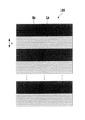
図5(a)から(c)は、本実施形態におけるマスクパターン110の一部を概念的に示した図である。マスクパターン110は、記録媒体の同一記録領域に記録すべき記録データを2回の走査に分割し各記録領域において記録媒体と記録ヘッドとが複数回相対移動(本実施形態では2回)して補完しながら完成させる所謂2パス記録方式に適合するマスクの一例である。そして、マスクパターン110は、記録率50%を越える高記録率領域Hnと、記録率50%を下回る低記録率領域Lnとを含んでいる。図5(a)は、第1ノズル列に適用される第1マスクパターン(C1として示した部分のみ)を説明する図であり、図5(b)は同様に第2ノズル列に適用される第2マスクパターン(C2として示した部分のみ)を説明する図である。また、図5(c)は、図5(a)、および(b)を合成したマスクパターンを示している。第1領域としての低記録率領域(高間引き率領域)Lnは、画像処理部76で2値化された記録データを高い間引き率で間引く領域である。また第2領域としての高記録率領域(低間引き率領域)Hnは、2値化された記録データを低い間引き率で間引いた領域である。なお本実施形態では、高記録率領域Hnは65%の記録率、低記録率領域Lnは35%の記録率に設定している。なお本実施形態において、マスクの記録率とは、所定領域に含まれる複数の画素のうち記録を許可する画素の割合であり、実際にドットが記録されるかは記録データにより決まる。
5A to 5C are diagrams conceptually showing a part of the
図5(a)に示されるように、第1ノズル列C1は上端から連続する4ノズル分が高記録率領域、次の4ノズル分が低記録率領域、さらに次の4ノズル分が高記録率領域となっており、このように高記録率領域と低記録率領域とが4ノズルずつ交互に設けられている。一方、図5(b)に示されるように、第2ノズル列C2は上端から連続する4ノズル分が低記録率領域、次の4ノズルが高記録率領域となっており、第1ノズル列とは反転するように高記録率領域と低記録率領域とが4ノズルずつ交互に設けられている。このように、第1ノズル列、第2ノズル列とも気流の通り道となる低記録率領域がノズル配列方向に4ノズル分の幅で複数設けられており、迂回気流による着弾位置ズレが抑制される。 As shown in FIG. 5A, in the first nozzle row C1, four nozzles continuous from the upper end are in a high recording rate area, the next four nozzles are in a low recording rate area, and the next four nozzles are in high recording. In this way, the high recording rate region and the low recording rate region are alternately provided by four nozzles. On the other hand, as shown in FIG. 5B, in the second nozzle row C2, the four nozzles continuous from the upper end are the low recording rate region, and the next four nozzles are the high recording rate region. The high recording rate region and the low recording rate region are alternately provided by four nozzles so as to be reversed. As described above, a plurality of low recording rate regions each having a width of four nozzles in the nozzle arrangement direction are provided in the first nozzle row and the second nozzle row in the direction of the air flow, and the landing position deviation due to the detour air current is suppressed. .
しかも、記録媒体上には第1ノズル列および第2ノズル列の足し合せで記録されるが、図5(c)に示すように、高記録率領域と低記録率領域とはノズル配列方向に沿って1画素単位で交互に配置している。このように、高記録率領域と低記録率領域とが1画素分という短い記録幅で交互に配置される。これによって、1パス目で高記録率領域、2パス目で低記録率領域として記録される領域と、1パス目で低記録率領域、2パス目で高記録率領域として記録される領域とに濃度ムラが発生しても目立たなくすることができる。 In addition, although the recording is performed by adding the first nozzle row and the second nozzle row on the recording medium, as shown in FIG. 5C, the high recording rate region and the low recording rate region are arranged in the nozzle arrangement direction. Are arranged alternately in units of one pixel. Thus, the high recording rate area and the low recording rate area are alternately arranged with a recording width as short as one pixel. Thus, an area recorded as a high recording rate area in the first pass, an area recorded as a low recording rate area in the second pass, an area recorded as a low recording rate area in the first pass, and a high recording rate area in the second pass. Even if density unevenness occurs, it can be made inconspicuous.
本実施形態の記録方法は、各記録領域を2回の走査で補完しながら完成させる。まず第1の走査で図5のマスクパターン110を用いて記録を行う。次に、記録ヘッド21のノズル列の長さの半分だけ記録媒体の搬送を行い、マスクパターン110の反転パターン(不図示)を用いて第2の走査を実行する。更に、前述と同様の搬送量の記録媒体搬送を行い、再びマスクパターン110を適用し、第1の走査を実行する。このように、第1の走査と第2の走査とを繰返して記録を行うことで画像を完成させる。このマスクパターン110を用いれば、図4に示すような高密度にノズルを配置したノズル列の記録ヘッドを高速走査して記録を行った場合にも、良好なインク滴の飛翔状態を得ることができる。これにより、着弾誤差の少ない良好な画像を形成することができる。
The recording method of the present embodiment is completed while complementing each recording area with two scans. First, printing is performed using the
ここで、高間引き率領域と低間引き率領域とが交互に配列されたマスクパターンを用いることよって、上述した着弾位置のズレが低減する理由(メカニズム)について説明する。シリアル方式やフルライン方式のインクジェット記録装置において、短時間で画像を完成させるためには、高い記録率で高速な相対走査を行うことが必要である。またその際、記録ヘッドと記録媒体との隙間に気流の乱れが生じることは上述した通りである。この気流の発生量と乱れ方は走査速度や記録率に大きく依存するが、マスクパターンにおける間引き率分布にも大きく依存している。本実施形態のように、ノズル配列方向の間引き率が高、低、高、低のように交互に配されたマスクパターンを用いると、高密度な吐出インクの壁に隙間が生じる。具体的には、マスクパターンの高間引き率領域に対応する箇所が隙間となることから、吐出インクの壁にはノズル配列方向に交互の隙間が生じる。すると、この隙間から気流が抜け、その分、迂回する気流の量が減り、結果的にこの迂回気流による着弾位置ズレも抑制される。 Here, the reason (mechanism) for reducing the deviation of the landing position described above by using the mask pattern in which the high thinning rate region and the low thinning rate region are alternately arranged will be described. In order to complete an image in a short time in a serial type or full line type inkjet recording apparatus, it is necessary to perform high-speed relative scanning at a high recording rate. At this time, the turbulence of the airflow is generated in the gap between the recording head and the recording medium as described above. The amount of generated air flow and how it is disturbed greatly depend on the scanning speed and the recording rate, but also greatly depend on the thinning rate distribution in the mask pattern. As in this embodiment, when mask patterns arranged alternately such that the thinning rate in the nozzle arrangement direction is high, low, high, and low are used, gaps are generated in the walls of the high-density ejected ink. Specifically, since a portion corresponding to the high thinning rate region of the mask pattern becomes a gap, alternate gaps are generated in the nozzle arrangement direction on the wall of the ejected ink. As a result, the airflow is removed from the gap, and the amount of the detouring airflow is reduced accordingly. As a result, the landing position deviation due to the detouring airflow is also suppressed.
ところで、ノズル配列方向における吐出インクの壁に気流が抜けるのには、十分な隙間を形成しなければならない。そのため従来の方法では、高間引き率領域は相応の領域幅を必要とし、1走査における濃淡パターンが目視で識別可能な大きさになることがあった。これは、各々の領域は異なる複数の走査によって画像が補完されるので、走査毎に記録濃度が異なる要素があった場合、マスクパターンをトレースした濃度ムラが記録画像に現れる。 By the way, a sufficient gap must be formed in order for airflow to escape through the wall of the ejected ink in the nozzle arrangement direction. For this reason, in the conventional method, the high thinning-out rate area needs to have a corresponding area width, and the grayscale pattern in one scan sometimes becomes a size that can be visually identified. This is because the image is complemented by a plurality of different scans in each region. Therefore, if there are elements having different print densities for each scan, density unevenness obtained by tracing the mask pattern appears in the print image.
ここで、記録画像に濃淡ムラが生じる原理を説明する。吐出液滴は細長い液柱状態で吐出口から射出された後、液柱が分断し、液柱先頭部分が主滴に、液柱尾引き部分がサテライト滴となって飛翔し、各々が主滴とサテライト滴として記録媒体上に着弾する。記録媒体上の主滴とサテライト滴との位置関係は各液滴の飛翔速度や、記録ヘッドと記録媒体間のギャップ、液滴が吐出口から射出される際の射出角度等によって変動する。 Here, the principle of occurrence of shading unevenness in the recorded image will be described. The ejected droplets are ejected from the ejection port in the form of an elongated liquid column, and then the liquid column is divided, and the liquid column head portion is ejected as the main droplet, and the liquid column tail portion is ejected as a satellite droplet. And land on the recording medium as satellite droplets. The positional relationship between the main droplet and the satellite droplet on the recording medium varies depending on the flying speed of each droplet, the gap between the recording head and the recording medium, the ejection angle when the droplet is ejected from the ejection port, and the like.
図6は、記録ヘッド21と記録媒体Pとの間で吐出液滴が飛翔する方向を示した図である。記録ヘッド21から吐出された主滴の射出方向dmと、サテライト滴の射出方向dsとが、キャリッジ走査方向Xにずれ成分を持った場合、往方向と復方向とで記録媒体Pに着弾した主滴とサテライト滴との着弾位置は大きく異なる。
FIG. 6 is a diagram showing the direction in which the ejected droplets fly between the
図7(a)、(b)は、記録媒体Pの画素内に着弾した主滴とサテライト滴との位置関係を模式的に示した平面図である。図7(a)は、図6に図示したような往方向(図6X方向)にキャリッジが移動している場合であり、図7(b)は、キャリッジが復方向に移動している場合を示している。図7(a)と図7(b)とを比較してわかるように、往方向で記録した場合は、復方向で記録した場合よりも1画素中のドット面積率が小さくなり記録画像としては薄くなってしまう。このような記録で記録率領域が目視可能な大きさを有する場合、記録画像には濃淡ムラが見えることになる。 FIGS. 7A and 7B are plan views schematically showing the positional relationship between main droplets and satellite droplets that have landed in the pixels of the recording medium P. FIG. 7A shows a case where the carriage is moving in the forward direction (X direction in FIG. 6) as shown in FIG. 6, and FIG. 7B shows a case where the carriage is moving in the backward direction. Show. As can be seen by comparing FIG. 7 (a) and FIG. 7 (b), when recording in the forward direction, the dot area ratio in one pixel is smaller than when recording in the backward direction. It will be thinner. In such a recording, when the recording rate area has a size that can be visually observed, unevenness in light and darkness is seen in the recorded image.
そこで本実施形態では、図5(c)に示すように、第1ノズル列および第2ノズル列がともに記録を終了した画像領域は、ノズル列方向(矢印α方向)の1画素毎に間引き率の異なるパターンで記録されている。従って、1走査内において間引き率の高低を繰返す空間周波数が最大になる。このため、異なる走査において、ドット面積率や吐出量等の変動要素があっても、目視での識別が不能な解像度で変動要素が分布するため、記録結果では濃度ムラとして認識できない。なおかつ、1回の走査における高記録率領域同士の間に存在する低記録率領域は、気流が抜けるのに十分な幅を備えており、気流による着弾位置ズレも抑制することができる。 Therefore, in the present embodiment, as shown in FIG. 5C, the image area where both the first nozzle row and the second nozzle row have finished recording is thinned out for each pixel in the nozzle row direction (arrow α direction). Are recorded in different patterns. Therefore, the spatial frequency that repeats the thinning rate within one scan is maximized. For this reason, even if there are fluctuating elements such as the dot area ratio and the discharge amount in different scans, the fluctuating elements are distributed at a resolution that cannot be visually identified. In addition, the low recording rate area existing between the high recording rate areas in one scan has a sufficient width to allow the airflow to escape, and the landing position deviation due to the airflow can also be suppressed.
このように、2パス記録による記録結果において、ノズル列方向で高記録率領域と低記録率領域とが1画素ごとに交互に配置されるように記録を行い、かつ記録中の高記録率領域同士の間に気流が抜けるのに十分な幅を持たせて記録を行う。これによって、記録ヘッドと記録媒体との間に発生する乱流を抑制し、マスクパターンに起因する濃度ムラを抑制することが可能なインクジェット記録装置およびインクジェット記録方法を実現することができた。 As described above, in the recording result by the two-pass recording, the recording is performed so that the high recording rate region and the low recording rate region are alternately arranged for each pixel in the nozzle row direction, and the high recording rate region being recorded is recorded. Recording is performed with a width sufficient for airflow to escape between them. Thus, an ink jet recording apparatus and an ink jet recording method capable of suppressing turbulent flow generated between the recording head and the recording medium and suppressing density unevenness due to the mask pattern can be realized.
なお上述の説明では、ノズル列C1、C2に適用されるマスクパターンにおいて、高記録率領域と低記録率領域は4ノズルの等間隔で交互に配置される構成であったが、高記録率領域と低記録率領域の周期はランダムであってもよい。すなわち、第1ノズル列C1は上端から4ノズル分が高記録率領域、次の2ノズル分が低記録率領域、さらに次の3ノズル分が高記録率領域というように、高記録率領域と低記録率領域との幅がランダムであってもよい。その場合、第2ノズル列C2のマスクは第1ノズル列C1のマスクと反転関係にあり、上端から4ノズル分が低記録率領域、次の2ノズル分が高記録率領域、さらに次の3ノズル分が低記録率領域となる。 In the above description, in the mask pattern applied to the nozzle rows C1 and C2, the high recording rate region and the low recording rate region are alternately arranged at equal intervals of 4 nozzles. The period of the low recording rate area may be random. That is, the first nozzle row C1 has a high recording rate area such that four nozzles from the upper end are a high recording rate region, the next two nozzles are a low recording rate region, and the next three nozzles are a high recording rate region. The width with the low recording rate area may be random. In this case, the mask of the second nozzle row C2 is in a reverse relationship with the mask of the first nozzle row C1, the four nozzles from the upper end are the low recording rate region, the next two nozzles are the high recording rate region, and the next three The nozzle portion becomes the low recording rate area.
また、本発明は2パス記録のみに適用できるものではなく、その他のパス数であってもよい。いずれのパス数であっても、高記録領域と低記録領域が記録される走査方向の組合せが領域ごとに異なることで発生する濃度ムラを軽減するという、本発明の目的を達成できる。ただし、2パスのような低パス記録において濃度ムラは発生しやすく、本発明はこのような低パス記録の構成に特に有用である。 Further, the present invention is not applicable only to two-pass printing, and other numbers of passes may be used. Regardless of the number of passes, it is possible to achieve the object of the present invention to reduce density unevenness that occurs when the combination of the scanning directions in which the high recording area and the low recording area are recorded differs from area to area. However, density unevenness is likely to occur in low pass recording such as two passes, and the present invention is particularly useful for such a low pass recording configuration.
また、第1ノズル列と第2ノズル列で高記録率領域と低記録率領域の記録率を異ならせてもよい。例えば、第1ノズル列の高記録率領域の記録率を65%、低記録率領域の記録率を35%とし、第2ノズル列の高記録率領域の記録率を70%、低記録率領域の記録率を30%としてもよい。 Further, the recording rates of the high recording rate region and the low recording rate region may be different between the first nozzle row and the second nozzle row. For example, the recording rate of the high recording rate region of the first nozzle row is 65%, the recording rate of the low recording rate region is 35%, the recording rate of the high recording rate region of the second nozzle row is 70%, and the low recording rate region The recording rate may be 30%.
21 記録ヘッド
32 キャリッジ
100 マスクパターン(従来)
110 マスクパターン(本実施形態)
P 記録媒体
n ノズル
21
110 Mask pattern (this embodiment)
P Recording medium n Nozzle
Claims (6)
前記第1ノズル列に対応する第1マスクパターンと前記第2ノズル列に対応する第2マスクパターンとを用い、前記第1ノズル列と第2ノズル列とにより記録すべき、前記同一の記録領域に対応する画像データを前記複数回の相対移動に分割する分割手段と、
前記複数回の移動それぞれにおいて、前記分割手段により分割された画像データに基づいて前記第1ノズル列と第2ノズル列とに画像を記録させる記録制御手段と、を備え、
前記第1マスクパターンと前記第2マスクパターンは、相対的に低い記録率の第1領域と相対的に高い記録率の第2領域とを前記ノズルの配列方向に対応する方向に交互に有し、前記第1マスクパターンの第1領域と前記第2マスクパターンの第2領域は前記対応する方向に同じ位置であり、前記第1マスクパターンの第2領域と前記第2マスクパターンの第1領域は前記対応する方向に同じ位置であることを特徴とするインクジェット記録装置。 A first nozzle row and a second nozzle row in which a plurality of nozzles that eject ink of the same color are arranged at a predetermined interval are arranged at a half of the predetermined interval in the arrangement direction of the plurality of nozzles. An inkjet recording apparatus that records an image on the recording medium by ejecting ink from the nozzles while relatively moving the recording head relative to the same recording area of the recording medium a plurality of times.
The same recording area to be recorded by the first nozzle row and the second nozzle row using a first mask pattern corresponding to the first nozzle row and a second mask pattern corresponding to the second nozzle row Dividing means for dividing the image data corresponding to the plurality of relative movements;
Recording control means for recording an image on the first nozzle row and the second nozzle row based on the image data divided by the dividing means in each of the plurality of movements;
The first mask pattern and the second mask pattern alternately have a first region having a relatively low recording rate and a second region having a relatively high recording rate in a direction corresponding to the arrangement direction of the nozzles. The first region of the first mask pattern and the second region of the second mask pattern are at the same position in the corresponding direction, and the second region of the first mask pattern and the first region of the second mask pattern Are the same positions in the corresponding directions.
前記第1ノズル列に対応する第1マスクパターンと前記第2ノズル列に対応する第2マスクパターンとを用い、前記第1ノズル列と第2ノズル列とにより記録すべき、前記同一の記録領域に対応する画像データを前記複数回の相対移動に分割する分割工程と、
前記複数回の移動それぞれにおいて、前記分割工程により分割された画像データに基づいて前記第1ノズル列と第2ノズル列とに画像を記録させる記録制御工程と、を備え、
前記第1マスクパターンと前記第2マスクパターンとに、相対的に低い記録率の第1領域と相対的に高い記録率の第2領域とを前記ノズルの配列方向に対応する方向に交互に備える工程と、
前記第1マスクパターンの第1領域と前記第2マスクパターンの第2領域とを、前記対応する方向に同じ位置に設け、前記第1マスクパターンの第2領域と前記第2マスクパターンの第1領域とを、前記対応する方向に同じ位置に設けることを特徴とするインクジェット記録方法。 A first nozzle row and a second nozzle row in which a plurality of nozzles that eject ink of the same color are arranged at a predetermined interval are arranged at a half of the predetermined interval in the arrangement direction of the plurality of nozzles. An inkjet recording method for recording an image on the recording medium by ejecting ink from the nozzle while moving the recording head relative to the same recording area of the recording medium a plurality of times.
The same recording area to be recorded by the first nozzle row and the second nozzle row using a first mask pattern corresponding to the first nozzle row and a second mask pattern corresponding to the second nozzle row Dividing step of dividing the image data corresponding to the plurality of relative movements,
A recording control step of recording an image on the first nozzle row and the second nozzle row based on the image data divided by the dividing step in each of the plurality of movements;
The first mask pattern and the second mask pattern are alternately provided with a first region having a relatively low recording rate and a second region having a relatively high recording rate in a direction corresponding to the arrangement direction of the nozzles. Process,
The first region of the first mask pattern and the second region of the second mask pattern are provided at the same position in the corresponding direction, and the second region of the first mask pattern and the first region of the second mask pattern are provided. An ink jet recording method comprising: providing regions at the same position in the corresponding direction.
Priority Applications (2)
| Application Number | Priority Date | Filing Date | Title |
|---|---|---|---|
| JP2009150075A JP2011005703A (en) | 2009-06-24 | 2009-06-24 | Ink jet recording apparatus and ink jet recording method |
| US12/816,732 US8287091B2 (en) | 2009-06-24 | 2010-06-16 | Inkjet printing apparatus and inkjet printing method |
Applications Claiming Priority (1)
| Application Number | Priority Date | Filing Date | Title |
|---|---|---|---|
| JP2009150075A JP2011005703A (en) | 2009-06-24 | 2009-06-24 | Ink jet recording apparatus and ink jet recording method |
Publications (2)
| Publication Number | Publication Date |
|---|---|
| JP2011005703A true JP2011005703A (en) | 2011-01-13 |
| JP2011005703A5 JP2011005703A5 (en) | 2012-08-09 |
Family
ID=43380235
Family Applications (1)
| Application Number | Title | Priority Date | Filing Date |
|---|---|---|---|
| JP2009150075A Pending JP2011005703A (en) | 2009-06-24 | 2009-06-24 | Ink jet recording apparatus and ink jet recording method |
Country Status (2)
| Country | Link |
|---|---|
| US (1) | US8287091B2 (en) |
| JP (1) | JP2011005703A (en) |
Cited By (3)
| Publication number | Priority date | Publication date | Assignee | Title |
|---|---|---|---|---|
| JP2012131135A (en) * | 2010-12-22 | 2012-07-12 | Riso Kagaku Corp | Density adjusting module and method for inkjet recording apparatus |
| JP2014188988A (en) * | 2013-03-28 | 2014-10-06 | Seiko Epson Corp | Printer and printing method |
| JP2019107810A (en) * | 2017-12-15 | 2019-07-04 | キヤノン株式会社 | Image processing device, image processing method and inkjet recording device |
Families Citing this family (4)
| Publication number | Priority date | Publication date | Assignee | Title |
|---|---|---|---|---|
| JP5787474B2 (en) * | 2009-10-08 | 2015-09-30 | キヤノン株式会社 | Image processing apparatus, image processing method, and program |
| JP6237178B2 (en) * | 2013-12-06 | 2017-11-29 | ブラザー工業株式会社 | Inkjet head and inkjet printer |
| JP6317141B2 (en) * | 2014-03-07 | 2018-04-25 | 株式会社ミマキエンジニアリング | Printing apparatus and printing method |
| JP6418036B2 (en) * | 2015-03-31 | 2018-11-07 | ブラザー工業株式会社 | Inkjet printer and inkjet head |
Citations (3)
| Publication number | Priority date | Publication date | Assignee | Title |
|---|---|---|---|---|
| JP2004106529A (en) * | 2002-08-30 | 2004-04-08 | Canon Inc | Method for adjusting recording position, ink jet recording device and ink jet recording system |
| JP2004243574A (en) * | 2003-02-12 | 2004-09-02 | Canon Inc | Ink jet recording head and ink jet recording method |
| JP2006192892A (en) * | 2004-12-13 | 2006-07-27 | Canon Inc | Ink-jet recording method and ink-jet recorder |
Family Cites Families (5)
| Publication number | Priority date | Publication date | Assignee | Title |
|---|---|---|---|---|
| JP3320317B2 (en) | 1996-09-03 | 2002-09-03 | キヤノン株式会社 | Ink jet printing apparatus and printing method |
| JP4666810B2 (en) | 2001-05-24 | 2011-04-06 | キヤノン株式会社 | Image recording apparatus and control method thereof |
| JP4603820B2 (en) | 2003-06-12 | 2010-12-22 | キヤノン株式会社 | Recording apparatus and recording method |
| WO2006064820A1 (en) | 2004-12-13 | 2006-06-22 | Canon Kabushiki Kaisha | Ink jet recording method and ink jet recording device |
| JP2008143091A (en) | 2006-12-12 | 2008-06-26 | Canon Inc | Inkjet recorder and inkjet recording method |
-
2009
- 2009-06-24 JP JP2009150075A patent/JP2011005703A/en active Pending
-
2010
- 2010-06-16 US US12/816,732 patent/US8287091B2/en not_active Expired - Fee Related
Patent Citations (3)
| Publication number | Priority date | Publication date | Assignee | Title |
|---|---|---|---|---|
| JP2004106529A (en) * | 2002-08-30 | 2004-04-08 | Canon Inc | Method for adjusting recording position, ink jet recording device and ink jet recording system |
| JP2004243574A (en) * | 2003-02-12 | 2004-09-02 | Canon Inc | Ink jet recording head and ink jet recording method |
| JP2006192892A (en) * | 2004-12-13 | 2006-07-27 | Canon Inc | Ink-jet recording method and ink-jet recorder |
Cited By (4)
| Publication number | Priority date | Publication date | Assignee | Title |
|---|---|---|---|---|
| JP2012131135A (en) * | 2010-12-22 | 2012-07-12 | Riso Kagaku Corp | Density adjusting module and method for inkjet recording apparatus |
| JP2014188988A (en) * | 2013-03-28 | 2014-10-06 | Seiko Epson Corp | Printer and printing method |
| JP2019107810A (en) * | 2017-12-15 | 2019-07-04 | キヤノン株式会社 | Image processing device, image processing method and inkjet recording device |
| JP7077003B2 (en) | 2017-12-15 | 2022-05-30 | キヤノン株式会社 | Image processing equipment, image processing methods and inkjet recording equipment |
Also Published As
| Publication number | Publication date |
|---|---|
| US20100328384A1 (en) | 2010-12-30 |
| US8287091B2 (en) | 2012-10-16 |
Similar Documents
| Publication | Publication Date | Title |
|---|---|---|
| JP4717620B2 (en) | Inkjet recording method and inkjet recording apparatus | |
| US7699436B2 (en) | Ink jet printing method and ink jet printing apparatus | |
| JP5063323B2 (en) | Inkjet recording apparatus and inkjet recording method | |
| JP5038076B2 (en) | Inkjet recording apparatus and inkjet recording method | |
| JP2011005703A (en) | Ink jet recording apparatus and ink jet recording method | |
| JP2013159017A (en) | Recording apparatus and recording control method | |
| JP2011126173A (en) | Inkjet recording system, inkjet recording method and program | |
| EP1790485B1 (en) | Inkjet recording device and inkjet recording method | |
| JP2003326750A (en) | Inkjet recorder and inkjet recording method | |
| JP2010058289A (en) | Fluid ejection device and fluid ejection method | |
| JP2008307793A (en) | Liquid discharge device and liquid discharge method | |
| JP4979485B2 (en) | Inkjet recording device | |
| JP2006168073A (en) | Inkjet recording system | |
| JP2008307722A (en) | Recording device and recording method | |
| JP2007038671A (en) | Inkjet recording device and inkjet recording method | |
| JP2009000836A (en) | Ink jet recording device and ink jet recording method | |
| JP5972037B2 (en) | Inkjet recording apparatus and inkjet recording method | |
| JP6238744B2 (en) | Recording control apparatus, recording apparatus, and recording control method | |
| JP2012025120A5 (en) | Image processing apparatus and image processing method | |
| JP2016175378A (en) | Droplet discharge device, mask pattern, and droplet discharge method | |
| JP5787474B2 (en) | Image processing apparatus, image processing method, and program | |
| JP6323039B2 (en) | PRINT CONTROL DEVICE, PRINT CONTROL METHOD, AND PROGRAM | |
| JP2014188988A (en) | Printer and printing method | |
| JP2010131826A (en) | Printing apparatus | |
| JP5460048B2 (en) | Inkjet recording apparatus and inkjet recording method |
Legal Events
| Date | Code | Title | Description |
|---|---|---|---|
| RD02 | Notification of acceptance of power of attorney |
Free format text: JAPANESE INTERMEDIATE CODE: A7422 Effective date: 20101106 |
|
| A521 | Written amendment |
Free format text: JAPANESE INTERMEDIATE CODE: A523 Effective date: 20120625 |
|
| A621 | Written request for application examination |
Free format text: JAPANESE INTERMEDIATE CODE: A621 Effective date: 20120625 |
|
| A131 | Notification of reasons for refusal |
Free format text: JAPANESE INTERMEDIATE CODE: A131 Effective date: 20130521 |
|
| A977 | Report on retrieval |
Free format text: JAPANESE INTERMEDIATE CODE: A971007 Effective date: 20130522 |
|
| A02 | Decision of refusal |
Free format text: JAPANESE INTERMEDIATE CODE: A02 Effective date: 20130924 |