JP5972037B2 - Inkjet recording apparatus and inkjet recording method - Google Patents
Inkjet recording apparatus and inkjet recording method Download PDFInfo
- Publication number
- JP5972037B2 JP5972037B2 JP2012106743A JP2012106743A JP5972037B2 JP 5972037 B2 JP5972037 B2 JP 5972037B2 JP 2012106743 A JP2012106743 A JP 2012106743A JP 2012106743 A JP2012106743 A JP 2012106743A JP 5972037 B2 JP5972037 B2 JP 5972037B2
- Authority
- JP
- Japan
- Prior art keywords
- recording
- ink
- color
- ejection port
- mask pattern
- Prior art date
- Legal status (The legal status is an assumption and is not a legal conclusion. Google has not performed a legal analysis and makes no representation as to the accuracy of the status listed.)
- Active
Links
- 238000000034 method Methods 0.000 title claims description 37
- 239000000976 ink Substances 0.000 claims description 280
- 238000003491 array Methods 0.000 claims description 83
- 239000003086 colorant Substances 0.000 claims description 23
- 238000010586 diagram Methods 0.000 description 21
- 238000001454 recorded image Methods 0.000 description 8
- 239000000758 substrate Substances 0.000 description 6
- 238000006243 chemical reaction Methods 0.000 description 4
- 238000006073 displacement reaction Methods 0.000 description 3
- 230000010354 integration Effects 0.000 description 3
- 230000000694 effects Effects 0.000 description 2
- 238000004088 simulation Methods 0.000 description 2
- 101100328887 Caenorhabditis elegans col-34 gene Proteins 0.000 description 1
- 238000001514 detection method Methods 0.000 description 1
- 238000009792 diffusion process Methods 0.000 description 1
- 238000007599 discharging Methods 0.000 description 1
- 238000005516 engineering process Methods 0.000 description 1
- 238000005187 foaming Methods 0.000 description 1
- 230000020169 heat generation Effects 0.000 description 1
- 230000007246 mechanism Effects 0.000 description 1
- 229910052709 silver Inorganic materials 0.000 description 1
- 239000004332 silver Substances 0.000 description 1
- -1 silver halide Chemical class 0.000 description 1
- GGCZERPQGJTIQP-UHFFFAOYSA-N sodium;9,10-dioxoanthracene-2-sulfonic acid Chemical compound [Na+].C1=CC=C2C(=O)C3=CC(S(=O)(=O)O)=CC=C3C(=O)C2=C1 GGCZERPQGJTIQP-UHFFFAOYSA-N 0.000 description 1
- 230000007723 transport mechanism Effects 0.000 description 1
Images


Landscapes
- Particle Formation And Scattering Control In Inkjet Printers (AREA)
- Ink Jet (AREA)
Description
本発明は、インクジェット記録装置およびインクジェット記録方法に関し、特に、集積密度が高い記録素子から少量のインクを吐出する記録ヘッドを用いて、高精細な画像を記録するために好適な記録技術に関するものである。 The present invention relates to an ink jet recording apparatus and an ink jet recording method, and particularly to a recording technique suitable for recording a high-definition image using a recording head that discharges a small amount of ink from a recording element having a high integration density. is there.
インクジェット記録装置においては、より一層の記録画像の高解像度化および記録速度の高速化を実現するために、記録ヘッドから吐出させるインクの少量化、インクの吐出周波数の向上、および多数の記録素子をより高密度に集積配列させる技術などが要求される。インクの吐出周波数は、記録素子の駆動周波数に対応する。また近年では、インクとして、シアン、マゼンタ、イエローおよびブラックの基本の4色に加えて、ライトシアン、ライトマゼンタ、およびグレーのような濃度の低いインクを同時に用いる技術も開発され、そのための記録装置も既に提供されている。濃度の低いインクを多く用いることは階調表現を豊かにし、また記録媒体へのインク滴の着弾位置のズレなどのノイズに対するロバスト性の向上に貢献する。このような技術を併用することにより、近年のインクジェット記録装置においては、高解像度および高階調の画像の高速記録して、銀塩写真に迫る高品位の画像が出力可能になってきている。 In an ink jet recording apparatus, in order to achieve higher resolution of recorded images and higher recording speed, the amount of ink ejected from the recording head is reduced, the ink ejection frequency is improved, and a large number of recording elements are provided. A technique for stacking and arranging higher density is required. The ink ejection frequency corresponds to the drive frequency of the recording element. In recent years, in addition to the basic four colors of cyan, magenta, yellow, and black, a technology that simultaneously uses low density inks such as light cyan, light magenta, and gray has been developed. Already provided. Using a lot of low-density ink enriches gradation expression and contributes to improvement of robustness against noise such as deviation of landing positions of ink droplets on a recording medium. By using such a technique together, in recent inkjet recording apparatuses, high-resolution and high-gradation images can be recorded at high speed, and high-quality images approaching those of silver halide photography can be output.
一方、記録素子の集積密度が高くて少量のインクを吐出可能な記録ヘッドを用いて、インクの吐出周波数を高くした場合には、「端部よれ」と称される現象が生じるおそれがある。 On the other hand, when the ink ejection frequency is increased using a recording head having a high integration density of recording elements and capable of ejecting a small amount of ink, there is a possibility that a phenomenon referred to as “end-to-end” may occur.
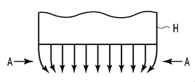
図1は「端部よれ」を説明するための模式図である。記録ヘッドHには、図1中の左右方向に沿って複数(例えば、768)の記録素子が配列されている。記録素子は、インクの吐出口、および、その吐出口からインクを吐出するためのエネルギーを発生する吐出エネルギー発生素子を含むものとする。このような記録ヘッドHの記録素子からは、図1中の下方に位置する不図示の記録媒体に向かってインク滴が吐出される。図1のように、同図中左右方向の記録素子列の両端部近傍に位置する記録素子から吐出されるインク滴は、その飛翔経路が記録素子列の中央に向かうように湾曲される。「端部よれ」は、このように記録素子列の両端部近傍に位置する記録素子から吐出されるインク滴の飛翔経路が湾曲する現象をいう。このような「端部よれ」は、次のような原理によって起こると考えられている。記録素子から吐出されたインク滴の周囲の空気は、そのインク滴と同じ方向に移動することにより、減圧状態となる領域を形成する。これに対して、記録ヘッドHの対向位置から外れた図1中左右の両側領域は減圧されないため、その両側領域の空気は、矢印Aのように減圧状態の領域に向かって移動する気流となる。その気流によって、図1のように、記録素子列の両端部近傍に位置する記録素子から吐出されるインク滴の飛翔経路が湾曲されることになる。このような「端部よれ」の現象は、高密度に配列された多数の記録素子の駆動周波数が高い場合に顕著に現れることが確認されている。 FIG. 1 is a schematic view for explaining “end-to-end”. In the recording head H, a plurality of (for example, 768) recording elements are arranged along the left-right direction in FIG. The recording element includes an ink discharge port and a discharge energy generating element that generates energy for discharging ink from the discharge port. From such recording elements of the recording head H, ink droplets are ejected toward a recording medium (not shown) positioned below in FIG. As shown in FIG. 1, the ink droplets ejected from the recording elements located in the vicinity of both ends of the recording element array in the left-right direction in FIG. 1 are curved so that their flight paths are directed toward the center of the recording element array. “End-to-end” refers to a phenomenon in which the flight path of ink droplets ejected from recording elements located in the vicinity of both ends of the recording element array is curved. Such “end-to-end” is considered to occur by the following principle. The air around the ink droplet ejected from the recording element moves in the same direction as the ink droplet, thereby forming a region in which the pressure is reduced. On the other hand, the left and right side regions in FIG. 1 that deviate from the position facing the recording head H are not depressurized, so the air in the both side regions becomes an airflow that moves toward the depressurized region as indicated by arrow A. . Due to the air flow, as shown in FIG. 1, the flight path of the ink droplets ejected from the recording elements located near both ends of the recording element array is curved. It has been confirmed that such a phenomenon of “end-of-edge” appears remarkably when the drive frequency of a large number of recording elements arranged at high density is high.
このような「端部よれ」が発生する状況では、記録素子列の両端部から吐出されたインク滴が記録媒体の正規の位置に着弾されない。そのため、記録ヘッドの走査と記録媒体の搬送とを繰り返して画像を記録するシリアルスキャン方式においては、記録ヘッドの前後の走査によって記録される画像のつなぎ部分に、記録濃度が薄い白すじ状の部分(白すじ)が生じるおそれがある。また、「端部よれ」の発生を抑えるために、記録ヘッドから吐出されるインク滴の体積を大きくして気流の影響を受けにくくした場合には、記録媒体に形成されるインクのドットが大きくなり、視覚的に記録画像の粒状感が目立つようになる。そのため、銀塩写真のように滑らかな高品位の画像を記録することが難しくなる。 In such a situation in which “end-to-end” occurs, the ink droplets ejected from both ends of the printing element array are not landed on the normal position of the printing medium. Therefore, in a serial scan method in which an image is recorded by repeatedly scanning the recording head and transporting the recording medium, a white streak-shaped portion having a low recording density is formed at a connecting portion of images recorded by scanning before and after the recording head. (White lines) may occur. Also, if the volume of ink droplets ejected from the recording head is increased to make it less susceptible to airflow in order to suppress the occurrence of “edge wobbling”, the ink dots formed on the recording medium become larger. As a result, the graininess of the recorded image becomes noticeable. Therefore, it becomes difficult to record a smooth high-quality image like a silver salt photograph.
特許文献1には、このような「端部よれ」の対策として、マスクパターンを用いて、記録素子列の端部に位置する記録素子の記録率を低くし、記録素子列の中央部に位置する記録素子の記録率を高くする方法が記載されている。また、特許文献2には、記録ディーティが高いと想定される記録素子列、あるいは記録デューティが高い記録素子列に対してのみ、「端部よれ」対策用のマスクパターンを用いる方法が記載されている。そのマスクパターンは、記録素子列の両端部に位置する記録素子の記録率を低くするためのマスクパターンである。
In
記録ヘッドの移動、および記録素子列の記録素子によるインクの吐出動作によって発生する気流は、その記録素子列に隣接する記録素子列の記録素子に対して、影響を及ぼすことが分かった。発明者らのシミュレーションツール等を活用した鋭意検討の末、互いに隣接する2つの記録素子列の記録デューティが異なる場合に、記録デューティの低い方の記録素子列から吐出されるインク滴の着弾位置が記録ヘッドの移動方向にずれることが分かった。 It has been found that the airflow generated by the movement of the recording head and the ink ejection operation by the recording elements in the recording element array affects the recording elements in the recording element array adjacent to the recording element array. As a result of diligent examination using the inventors' simulation tools and the like, when the print duty of two print element arrays adjacent to each other is different, the landing position of the ink droplet ejected from the print element array with the lower print duty is It was found that the recording head shifted in the moving direction.
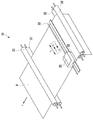
図2(a),(b)は、記録ヘッドHにおける2つの隣接する記録素子列L1,L2から異なる記録デューティでインク滴を吐出させながら、同図中の左右方向に記録走査したときの、記録ヘッドHと記録媒体Pとの間の気流を示すモデル図である。複数の記録素子が配列される記録素子列L1,L2は、それぞれ図2(a),(b)中の紙面の表裏方向に延在している。図2(a)のような右方への記録走査時は、記録デューティの高い記録素子列L1が走査方向の前方に位置し、記録デューティの低い記録素子列L2が走査方向の後方に位置する。一方、図2(b)のような左方への記録走査時は、記録デューティの低い記録素子列L2が走査方向の前方に位置し、記録デューティの高い記録素子列L1が走査方向の後方に位置する。図2(a)の場合には、記録デューティが低い記録素子列l2の直下に、記録媒体Pから記録ヘッドH方向に巻き上げられながら走査方向の後方に向かう気流A1が確認できた。一方、図2(b)の場合には、記録デューティが低い記録素子列L2の直下に、記録ヘッドHから記録媒体Pに吹き下ろされながら走査方向の前方に向かう気流A2が確認できた。気流A1よりも気流A2の方が、記録素子列L2から吐出されるインク滴の速度ベクトルに近いため、記録素子列L2から吐出されたインク滴の着弾は、その気流A2の影響を受けやすくなる。したがって図2(b)の場合、記録素子列L2から吐出されたインク滴の着弾位置は、走査方向の後方、つまり記録デューティが高い記録素子列L1寄にずれやすくなる。 FIGS. 2A and 2B are diagrams when recording scanning is performed in the left-right direction in FIG. 2 while ejecting ink droplets from two adjacent recording element arrays L1 and L2 in the recording head H at different recording duties. 3 is a model diagram showing an air flow between a recording head H and a recording medium P. FIG. The recording element rows L1 and L2 in which a plurality of recording elements are arranged extend in the front and back direction of the paper surface in FIGS. 2 (a) and 2 (b), respectively. At the time of the recording scan to the right as shown in FIG. 2A, the recording element row L1 having a high recording duty is located in the front in the scanning direction, and the recording element row L2 having a low recording duty is located in the rear in the scanning direction. . On the other hand, at the time of the recording scan to the left as shown in FIG. 2B, the recording element row L2 with a low recording duty is positioned in front of the scanning direction, and the recording element row L1 with a high recording duty is behind in the scanning direction. To position. In the case of FIG. 2 (a), an airflow A1 directed backward in the scanning direction while being wound up from the recording medium P in the direction of the recording head H can be confirmed immediately below the recording element array l2 having a low recording duty. On the other hand, in the case of FIG. 2B, an airflow A2 directed forward in the scanning direction while being blown down from the recording head H to the recording medium P can be confirmed immediately below the recording element array L2 having a low recording duty. Since the airflow A2 is closer to the velocity vector of the ink droplets ejected from the recording element array L2 than the airflow A1, the landing of the ink droplets ejected from the recording element array L2 is more susceptible to the airflow A2. . Accordingly, in the case of FIG. 2B, the landing positions of the ink droplets ejected from the recording element array L2 are likely to be shifted backward in the scanning direction, that is, toward the recording element array L1 having a high recording duty.
このように、隣接する記録素子列L1,L2の記録デューティの差は、それらの記録素子列から吐出されるインク滴の着弾位置に影響を及ぼす。特に、図2(b)のように走査方向の前方に記録デューティの低い記録素子列L2が位置する場合には、その記録素子列L2から吐出されたインク滴が走査方向の後方側に引き寄せられて、着弾位置のずれを生じるおそれがある。特に、マルチパス記録方式において、記録素子列の方向に記録率が変化するグラデーションマスクを使用している場合には、記録素子列の中央部の記録率が高くなるために、その中央部から吐出されるインクによって生じる気流の影響が大きくなりやすい。具体的には、その気流によって、隣接する記録素子列の中央部から吐出されるインク滴の着弾位置のずれが大きくなりやすい。グラデーションマスクを用いることにより、マルチパス記録方式における白すじの発生を抑えることができる反面、記録素子列の中央部から吐出されるインク滴の着弾位置のずれが記録画像に及ぼす影響は大きくなる。さらに、記録デューティが低い記録素子列から吐出されるインクと同色系のインクを吐出するために他の記録素子列が備えられていない場合には、そのインクの着弾位置のずれが記録画像に及ぼす影響は大きくなる。記録デューティが低い記録素子列から吐出されるインクを異なる量で吐出する他の記録素子列を備えていない場合も同様である。 As described above, the difference in recording duty between the adjacent recording element arrays L1 and L2 affects the landing position of the ink droplets ejected from these recording element arrays. In particular, as shown in FIG. 2B, when the recording element row L2 having a low recording duty is positioned in front of the scanning direction, the ink droplets ejected from the recording element row L2 are attracted to the rear side in the scanning direction. This may cause the landing position to shift. In particular, in a multi-pass printing method, when a gradation mask that changes the recording rate in the direction of the printing element array is used, the recording rate at the center of the printing element array becomes high, so that the discharge from the center is performed. The influence of the airflow generated by the ink that is applied tends to increase. Specifically, the deviation of the landing positions of the ink droplets ejected from the central part of the adjacent recording element arrays is likely to increase due to the air flow. By using the gradation mask, it is possible to suppress the occurrence of white streaks in the multi-pass printing method, but on the other hand, the influence of the deviation of the landing position of the ink droplets ejected from the central portion of the printing element array on the printed image becomes large. Further, when no other recording element array is provided for ejecting ink of the same color as the ink ejected from the recording element array having a low recording duty, the deviation of the landing position of the ink affects the recorded image. The impact will be greater. The same applies to the case where there is no other recording element array that ejects different amounts of ink ejected from the recording element array having a low recording duty.
また、上述したような気流の影響を小さく抑えるために、隣接する記録素子列間の距離を大きくした場合には、記録素子の配置の高密度化に逆行し、記録ヘッドおよびインクジェット記録装置の大型化を招くおそれがある。 Further, in order to suppress the influence of the airflow as described above, when the distance between the adjacent recording element arrays is increased, the recording head and the ink jet recording apparatus are increased in size, contrary to the increase in the density of the recording elements. There is a risk that
本発明の目的は、マルチパス記録方式において、互いに隣接する記録素子列間における気流の影響を抑えて、高精細な画像を記録することができるインクジェット記録装置およびインクジェット記録方法を提供することにある。 An object of the present invention is to provide an ink jet recording apparatus and an ink jet recording method capable of recording a high-definition image while suppressing the influence of an air flow between adjacent recording element arrays in a multi-pass recording method. .
本発明のインクジェット記録装置は、第1の色のインクを吐出する複数の吐出口が所定方向に配列された第1の吐出口列と、前記第1の色と異なる第2の色のインクを吐出する複数の吐出口が前記所定方向に配列された第2の吐出口列と、前記第2の色と同系色であり、前記第2の色と濃度が異なる色である第3の色のインクを吐出する複数の吐出口が前記所定方向に配列された第3の吐出口列と、を少なくとも含む複数の色のインクを吐出するための複数の吐出口列が、前記第1の吐出口列と前記第2の吐出口列が前記所定方向と交差する交差方向に隣接するように、前記交差方向に並んで配置された記録ヘッドと、前記記録ヘッドを記録媒体上の単位領域に対して前記交差方向に複数回走査させる走査手段と、前記単位領域に記録する画像に対応する画像データを取得する第1の取得手段と、前記第1の取得手段によって取得された前記画像データと、それぞれ前記複数の吐出口列のそれぞれの位置における記録率を定める複数のマスクパターンと、に基づいて、前記走査手段による前記複数回の走査のそれぞれにて前記単位領域にインクを吐出するために用いる記録データを生成する生成手段と、前記走査手段によって走査されている前記記録ヘッドから、前記生成手段によって生成された前記記録データに基づいてインクを吐出するように制御する制御手段と、を有するインクジェット記録装置であって、前記複数の吐出口列の中に、前記第1の吐出口列以外に前記第1の色と同系色のインクを吐出する吐出口列は存在せず、前記生成手段は、(i)前記第1の取得手段によって取得された前記第1の色のインクに対応する前記画像データと、前記複数のマスクパターンのうちの第1のマスクパターンと、に基づいて、前記第1の色のインクに対応する前記記録データを生成し、(ii)前記第1の取得手段によって取得された前記第2の色のインクに対応する前記画像データと、前記複数のマスクパターンのうちの、前記吐出口列の前記所定方向の端部における記録率と中央部における記録率の差分が前記第1のマスクパターンよりも小さく、且つ、前記吐出口列の前記所定方向の中央部における記録率が前記第1のマスクパターンよりも低い第2のマスクパターンと、に基づいて、前記第2の色のインクに対応する前記記録データを生成することを特徴とする。 The inkjet recording apparatus of the present invention includes a first ejection port array in which a plurality of ejection ports for ejecting a first color ink are arranged in a predetermined direction, and a second color ink different from the first color. a second ejection outlet array in which a plurality of discharge ports are arranged in the predetermined direction for ejecting said a second color and similar colors, a third color is a color that the second color and different concentrations A plurality of ejection port arrays for ejecting ink of a plurality of colors including at least a third ejection port array in which a plurality of ejection ports for ejecting ink are arranged in the predetermined direction are the first ejection ports. A recording head arranged in the intersecting direction so that the array and the second ejection port array are adjacent to each other in the intersecting direction intersecting the predetermined direction; and the recording head with respect to a unit area on the recording medium Scanning means for scanning in the intersecting direction a plurality of times, and an image to be recorded in the unit area A plurality of mask patterns for determining a recording rate at each position of each of the plurality of ejection port arrays; and a first acquisition unit that acquires image data corresponding to the image data; the image data acquired by the first acquisition unit; And generating means for generating recording data used for ejecting ink to the unit area in each of the plurality of scans by the scanning means, and the recording head being scanned by the scanning means Control means for controlling the ink to be ejected based on the recording data generated by the generating means, wherein the first ejection ports are arranged in the plurality of ejection port arrays. There is no ejection port array that ejects ink of the same color as the first color other than the ejection port array, and the generation unit includes (i) the first acquisition unit. The first color ink corresponding to the first color ink based on the image data corresponding to the first color ink and the first mask pattern of the plurality of mask patterns. It generates recording data, (ii) and the image data corresponding to the ink of said acquired by the first acquisition means second color, of the plurality of mask patterns, the predetermined said discharge port array direction of the difference between the recording rate in the recording rate and the central portion of the end portion is rather smaller than the first mask pattern, and the predetermined direction wherein the recording rate at the central portion of the first mask pattern of the discharge port array a low There second mask patterns than, based on, and generates the recording data corresponding to the ink of the second color.
本発明によれば、記録素子列から吐出されるインクの種類および記録デューティのうちの少なくとも一方と、その記録素子列に隣接する記録素子列から吐出されるインクの種類と、に応じて、記録データを間引くためマスクパターンを異ならせる。これにより、互いに隣接する記録素子列間における気流の影響を抑えて、高精細な画像をより記録することができる。 According to the present invention, recording is performed according to at least one of the type of ink ejected from the recording element array and the recording duty, and the type of ink ejected from the recording element array adjacent to the recording element array. Different mask patterns are used to thin out data. Thereby, the influence of the airflow between the recording element arrays adjacent to each other can be suppressed, and a high-definition image can be recorded more.
(第1の実施形態)
図19は、第1の実施形態に適用するインクジェット記録装置30の構成例を説明するための斜視図である。
(First embodiment)
FIG. 19 is a perspective view for explaining a configuration example of the ink
インクを吐出可能な記録ヘッド20は、矢印Xの主走査方向に移動可能なキャリッジ31に着脱可能に搭載され、記録媒体Pは、2つの搬送ローラ対33,34によって、主走査方向と交差(本例の場合は、直交)する矢印Yの副走査方向に搬送される。キャリッジ31は、ガイドシャフト34などによって主走査方向に移動自在にガイドされ、後述するキャリッジモータやベルトなどによって構成される移動機構によって主走査方向に往復移動される。
The
図3は、図19の記録装置30の制御系の構成を説明するためのブロック図である。CPU2は、インターフェース6を介して接続された外部のホスト装置1からの入力信号(画像信号を含む)にしたがって、記録動作を含む記録装置全体の動作を制御する。CPU2が実行する処理プログラムはROM3に格納されており、RAM4は、処理中の画像信号を一時的に保存するなどのワークエリアとして利用されている。記録ヘッド20は、記録ヘッドドライバ5によって駆動され、キャリッジ31を移動させるためのキャリッジモータ8はモータドライバ7によって駆動される。モータドライバ9は、搬送ローラ対33,34などを作動させるための搬送モータ10を駆動し、モータドライバ11は、記録媒体Pを給紙するための給紙モータ12を駆動する。
FIG. 3 is a block diagram for explaining the configuration of the control system of the
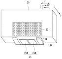
図4は、記録ヘッド20の概略斜視図である。複数の記録素子が形成された2枚の記録素子基板21(21A,21B)は、支持基盤22上に設けられており、それらの記録素子は、後述するように記録素子列を形成するように複数配列されている。記録素子は、不図示のインク供給ユニットから供給されたインクを駆動信号に基づいてZ方向にインク滴として吐出する。記録素子は、インクの吐出口と、インク供給ユニットから供給されたインクを吐出口から吐出するための吐出エネルギー発生素子と、を含み、その吐出エネルギー発生素子に駆動パルスが印加されることにより、吐出口からインクを吐出する構成となっている。吐出エネルギー発生素子としては、電気熱変換素子(ヒータ)やピエゾ素子などを用いることができる。電気熱変換素子を用いた場合には、その発熱によりインクを発泡させ、その発泡エネルギーを利用して吐出口からインクを吐出することができる。駆動パルスを生成するための駆動信号は、コンタクト端子基板23およびシート配線基板24等を介して記録素子基板21に入力される。
FIG. 4 is a schematic perspective view of the
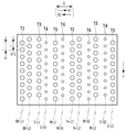
図5は、記録ヘッド20に複数備わる記録素子列の説明図である。記録素子基板21Aには、ライトシアン(LC)、マゼンタ(M)、イエロー(Ye)、ライトマゼンタ(LM)の4種のインクを吐出するための記録素子列が、主走査方向と交差(本例の場合は、直交)する方向に延在するように形成されている。一方、記録素子基板21Bには、シアン(C)、ブラック(Bk)、ライトグレー(LGy)、グレー(Gy)の4種のインクを吐出するための記録素子列が、主走査方向と交差(本例の場合は、直交)する方向に延在するように形成されている。
FIG. 5 is an explanatory diagram of a plurality of recording element arrays provided in the
図3において、CPU2は、ホスト装置1から入力した画像信号に基づいて記録ヘッドドライバ5を制御し、記録ヘッド20の記録素子からインクを吐出させる。同時に、キャリッジモータドライバ7を制御することにより、キャリッジモータ8を駆動して、記録ヘッド20と共にキャリッジ31を主走査方向に移動させる。このように、記録ヘッド20を移動させつつ、その記録ヘッド20からインクを吐出することにより、記録走査の1回分の画像が記録媒体Pに記録される。このような1回の記録走査と、搬送モータ10の駆動力による記録媒体Pの所定量の搬送と、を交互に行うことにより、記録媒体Pに順次画像が記録される。
In FIG. 3, the
図6は、ホスト装置1と記録装置30を含む記録システムの説明図である。ホスト装置1は、アプリケーション41とプリンタドライバ42を備えている。アプリケーション41は、入力情報に基づいて、プリンタドライバ42を介して記録装置30の記録制御、記録媒体Pの搬送機構の制御、およびキャリッジ31の移動制御などを行う。
FIG. 6 is an explanatory diagram of a recording system including the
プリンタドライバ42において、色補正部43は、アプリケーション41から入力した画像信号に対して、出力しようとする画像特性に合わせた色補正を行い、その画像信号を異なる信号に変換する。色変換部44は、入力されたRGB信号を、出力する記録装置30が使用するインク色に対応する信号に変換する。本例においては、シアン(C)、マゼンタ(M)、イエロー(Ye)、ブラック(Bk)、ライトシアン(LC)、ライトマゼンタ(LM)、グレー(Gy)、ライトグレー(LGy)の計8色のインクを使用可能である。ハーフトーニング部45は、入力されたインク色毎の多値信号に対して、誤差拡散等の擬似中間調処理(ハーフトーニング処理)を行って、その多値信号を、記録装置30が記録動作を実現するための階調数すなわち1ビットに付き2値の信号に変換する。
In the
プリンタドライバ42における記録モード制御部46は、プリンタドライバ42のユーザインターフェース上における記録媒体や記録品位の指定内容によって、色補正部43、色変換部44、ハーフトーニング部45で用いる各パラメータを設定する。また、記録モード制御部46は、記録モード情報を制御コマンドとして記録装置30に転送する。
The recording
記録装置30に備わるプリントバッファ47には、プリンタドライバ42においてハーフトーニング処理された2値の記録データが入力され、1走査分の記録データが、記録ヘッド20における記録素子のそれぞれに対応するようにマスク制御部50に転送される。マスク制御部50は、後述するように、プリンタドライバ42から転送される記録モード情報に基づいて、マルチパス方式の記録のために用意された複数のマスク(グラデーションマスク)のパターンの中から適切なものを選択する。そして、その選択したマスクパターンを用いて、入力された2値の記録データに対してマスク処理を行う。マスク処理により間引かれた2値の記録データは、記録ヘッドドライバ5に転送され、記録ヘッド20の各記録素子を駆動するための電気信号に変換される。その記録ヘッドドライバ5にて生成された電気信号は、記録ヘッド20の各記録素子に対して所定のタイミングで転送され、これにより、各記録素子が電気信号に応じてインクを吐出する。このように記録ヘッド20は、記録媒体上の単位記録領域を複数回走査するマルチパス方式において、マスク処理により走査毎に間引かれた記録データに基づいてインクを吐出する。
The
このようなホスト装置1と記録装置30を含む記録システムは、1つの記録装置を構成するものであってもよく、また、マスク制御部50の少なくとも一部はホスト装置1側に備えてもよい。
Such a recording system including the
図7は、マスク制御部50をさらに詳細に示したブロック図である。第1セレクタ51は、プリンタドライバ42から転送される記録モード情報の中の1つの情報である記録品位が「きれい」か「標準」であるかに応じて、つまり「きれいモード」であるか「標準モード」であるかに応じて、記録データを分ける。「きれいモード」であれば、全8色分のインクに対応する2値の記録データが第1マスク制御部52に転送される。一方、「標準モード」であれば、インクの属性に応じて第2セレクタ53が記録データを分ける。「標準モード」の場合には、「きれいモード」よりもマルチパス記録方式におけるパス数が少なく、1記録走査(1パス)当たりの記録デューティが高くなるため、記録素子列間の記録デューティの差が発生しやすいと想定する。したがって、記録モードが「きれいモード」であるか「標準モード」であるかを判定することは、間接的に、記録デューティを判定することになる。
FIG. 7 is a block diagram showing the
「標準モード」の場合には、インク色毎の記録データをインクの属性に応じて分ける。そのインクの属性は、インクが支配色であるか否かの属性であり、支配色であるシアン(C)、マゼンタ(M)、イエロー(Ye)、ブラック(Bk)のインクに対応する2値の記録データは、第1マスク制御部52へ転送される。支配色ではないライトシアン(LC)、ライトマゼンタ(LM)、グレー(Gy)、ライトグレー(LGy)の4色のインクに対応する記録データは、第3セレクタ54において、隣接する記録素子列の情報に基づいて分けられる。
In the “standard mode”, the recording data for each ink color is divided according to the attribute of the ink. The attribute of the ink is an attribute indicating whether or not the ink is the dominant color, and binary corresponding to the dominant colors of cyan (C), magenta (M), yellow (Ye), and black (Bk). Is transferred to the first
第3セレクタ54は、隣接する記録素子列から吐出されるインクと同系色の濃インクまたは淡インクが、記録装置において用いられるインクの中にある否かに応じて、支配色ではない4色のインクに対応する記録データを分ける。以下、支配色ではない4色のインクに対応する記録素子列を「本記録素子列」、また、それに隣接する記録素子列を「隣接記録素子列」ともいう。記録装置において用いられるインクの中に、隣接記録素子列から吐出されるインクと同系色である濃インクまたは淡インクがある場合、本記録素子列に対応する2値の記録データは、第1マスク制御部52へ転送される。一方、記録装置において用いられるインクの中に、隣接録素子列から吐出されるインクと同系色である濃インクまたは淡インクがない場合、本記録素子列に対応する2値の記録データは、第2マスク制御部55へ転送される。
The
本例の場合は、同系色である濃インクまたは淡インクが用いられないインクは、イエロー(Ye)のインクのみである。また、図5のように、支配色ではない4色のインクを吐出する記録素子列の中において、イエロー(Ye)のインクを吐出する記録素子列と隣接する記録素子列は、ライトマゼンタ(LM)のインクを吐出する記録素子列である。結局、ライトマゼンタ(LM)に対応する2値の記録データのみが第2マスク制御部55へ転送されることになる。
In the case of this example, the yellow (Ye) ink is the only ink that does not use dark or light inks of similar colors. Also, as shown in FIG. 5, among the recording element arrays that eject four colors of ink that are not the dominant colors, the recording element array adjacent to the recording element array that ejects yellow (Ye) ink is light magenta (LM). ). Eventually, only binary recording data corresponding to light magenta (LM) is transferred to the
第1マスク制御部52には、第1マスクパターン(マスクパターンA)が格納されており、第2マスク制御部55には、第2マスクパターン(マスクパターンB)が格納されている。第1および第2マスク制御部52,55は、それぞれのマスクパターンを用いて記録データをマスク処理し、そのマスク処理後の記録データを記録ヘッドドライバ5へ転送する。支配色であるシアン(C)、マゼンタ(M)、イエロー(Ye)、ブラック(Bk)のインクに対応する2値の記録データは、マスクパターンAを用いてマスク処理される。支配色ではないライトシアン(LC)、グレー(Gy)、ライトグレー(LGy)のインクに対応する2値の記録データは、マスクパターンAを用いてマスク処理される。また、支配色ではないライトマゼンタ(LM)のインクに対応する記録データは、マスクパターンBを用いてマスク処理される。
The first
図8は、本例において用いられる4パスのマルチパス記録用の2つのマスクパターンA,Bの説明図である。マスクパターンAにおいては、記録素子列の端部に位置する記録素子による記録率が約10%、その中央部に位置する記録素子による記録率が40%となっている。一方、マスクパターンBにおいては、記録素子列の端部に位置する記録素子による記録率が約15%、その中央部に位置する記録素子による記録率が35%となっている。記録素子列の端部に位置する記録素子の記録率に関して、マスクパターンAにおける値を所定値とした場合、マスクパターンBにおいては、その所定値よりも大きい値となる。なお、本明細書において「記録率」とは、マスクパターンにより定められる記録許容ドット数の割合のことであり、詳しくは、マスクパターンの領域に対応した全ドット数に対して、記録が許容されるドット数(記録許容ドット数)の割合のことである。また、記録素子と記録率は、1:1の関係であってもよく、また複数:1の関係であってもよい。 FIG. 8 is an explanatory diagram of two mask patterns A and B for 4-pass multi-pass printing used in this example. In the mask pattern A, the recording rate by the recording element located at the end of the printing element array is about 10%, and the recording rate by the recording element located at the center is 40%. On the other hand, in the mask pattern B, the recording rate by the recording element located at the end of the printing element array is about 15%, and the recording rate by the recording element located at the center is 35%. With respect to the recording rate of the recording element located at the end of the recording element array, when the value in the mask pattern A is a predetermined value, the mask pattern B has a value larger than the predetermined value. In this specification, the “recording rate” is the ratio of the number of dots allowed for printing determined by the mask pattern. Specifically, printing is allowed for the total number of dots corresponding to the area of the mask pattern. This is the ratio of the number of dots to be recorded (number of printable dots). Further, the recording element and the recording rate may have a 1: 1 relationship or a plurality of 1: 1 relationship.
マスクパターンBは、マスクパターンAと同様に記録素子列の端部の記録率が低く、その中央部の記録率が高く設定されているが、マスクパターンAほど記録率の高低差が大きくない。マスクパターンAのように記録率の高低差の大きいマスクパターンは、記録素子列の端部の記録率を小さくするため、前述したように気流による「端部よれ」を抑制することになる。しかし、記録素子列の中央部の記録デューティが高い分、その記録素子列に隣接する記録素子列に及ぼす気流の影響は大きくなる。 Like the mask pattern A, the mask pattern B has a low recording rate at the end of the printing element array and a high recording rate at the center, but the mask pattern A does not have a large difference in recording rate. A mask pattern having a large difference in recording rate, such as the mask pattern A, reduces the recording rate at the end of the recording element array, and thus suppresses “end-to-end” due to the air current as described above. However, since the recording duty at the central portion of the recording element array is high, the influence of the airflow on the recording element array adjacent to the recording element array is increased.
ここで、互いに隣接する記録素子列の記録デューティの差と、それらの記録素子列の主走査方向におけるインクの着弾位置ずれと、の関係について説明する。以下の着弾位置のずれデータは、シミュレーションツールによって得られたものである。 Here, a description will be given of the relationship between the print duty difference between the print element arrays adjacent to each other and the landing position deviation of the ink in the main scanning direction of the print element arrays. The following landing position deviation data is obtained by a simulation tool.
図5の記録ヘッドにおいて互いに隣接する記録素子列のうち、ライトマゼンタ(LM)の記録素子列の記録デューティを50%とし、イエロー(Ye)の記録素子列を記録デューティ12.5%として、4パスのマルチパス記録を実行した場合を想定する。ここでは仮に、それらの記録素子列の記録データは、いずれも図8(a)のマスクパターンA(端部10%、中央部40%)を用いてマスク処理することとする。ライトマゼンタ(LM)の記録素子列(以下、「記録素子列LM」ともいう)の中央部の1走査当たりの記録デューティは、(50/4)×(40/25)=20%となる。一方、イエロー(Ye)の記録素子列(以下、「記録素子列Ye」ともいう)の中央部の1走査当たりの記録デューティは、(12.5/4)×(40/25)=5%となる。また、これらの式において、(40/25)は、4パスの記録方式における記録率の平均(25%)に対する中央部の記録率(40%)の割合を意味する。このような記録デューティ差の条件で往復走査したときに、イエロー(Ye)の記録素子列から吐出されたインク滴の走査方向の着弾位置ずれは、図15(a),(b)および図16のように生じた。これらの図の縦軸は、記録ヘッドの走査方向を正にしたときの着弾位置のずれ量(ヨレ量)を数値化したものである。
Of the recording element arrays adjacent to each other in the recording head of FIG. 5, the recording duty of the light magenta (LM) recording element array is 50%, and the yellow (Ye) recording element array is 42.5%. Assume that multi-pass recording is performed. Here, it is assumed that the recording data of these recording element arrays are all masked using the mask pattern A (the
図15(a)および(b)は、それぞれ、記録ヘッドを矢印X1方向に往走査および矢印X2に復走査させたときに記録素子列Yeから吐出されるイエロー(Ye)のインク滴(主滴)の着弾位置ずれを示す。往走査時は、図15(a)のように、記録素子列Yeの中央部から吐出されるイエロー(Ye)のインク滴の着弾位置が走査方向とは逆の方向、つまり記録素子列LMの方向に3μmほどずれた。一方、復走査時は、図15(b)のように、記録素子列Yeの全域から吐出されるイエロー(Ye)のインク滴の着弾位置には特異的なずれが現れない。図16は、往走査時に記録素子列Yeから吐出されるイエロー(Ye)のインクの小滴(サテライト)の着弾位置ずれを示す。サテライトは、インク滴(主滴)の後に遅れて吐出されるインクの小滴であり、インク滴に遅れて着弾する。サテライトは、その吐出速度が遅く、その質量が小さいために気流の影響を受けやすく、その着弾位置のずれは10μm近くにまでに達する。 FIGS. 15A and 15B show yellow (Ye) ink droplets (main droplets) ejected from the recording element array Ye when the recording head is moved forward and backward in the direction of the arrow X1 and X2, respectively. ) Shows landing position deviation. At the time of forward scanning, as shown in FIG. 15A, the landing position of yellow (Ye) ink droplets ejected from the central portion of the recording element array Ye is in the direction opposite to the scanning direction, that is, in the recording element array LM. The direction shifted by about 3 μm. On the other hand, during backward scanning, as shown in FIG. 15B, there is no specific deviation in the landing positions of yellow (Ye) ink droplets ejected from the entire area of the printing element array Ye. FIG. 16 shows the landing position deviation of a small droplet (satellite) of yellow (Ye) ink ejected from the printing element array Ye during forward scanning. A satellite is a small droplet of ink ejected after an ink droplet (main droplet), and landed after the ink droplet. The satellite is slow in discharge speed and small in mass, and thus is easily affected by air current, and the displacement of its landing position reaches nearly 10 μm.
これらのデータから、図2(a),(b)を用いて説明した走査方向とインク滴の着弾位置のずれとの関係が証明された。つまり、図2(b)のように、走査方向の前方に記録デューティの低い記録素子列(記録素子列Ye)が位置する場合に、その記録素子列から吐出されたインク滴が記録デューティの高い記録素子列LM側(走査方向の後方側)に引き寄せられることが証明された。 From these data, the relationship between the scanning direction described with reference to FIGS. 2A and 2B and the deviation of the landing position of the ink droplet was proved. That is, as shown in FIG. 2B, when a printing element row (printing element row Ye) with a low printing duty is positioned in front of the scanning direction, ink droplets ejected from the printing element row have a high printing duty. It has been proved that it is attracted to the recording element array LM side (rear side in the scanning direction).
本実施形態においては、イエロー(Ye)のインク滴の着弾位置のずれを小さく抑えるために、記録素子列LMの記録データに適用するマスクパターンを図8(b)のマスクパターンB(端部15%、中央部35%)とする。記録素子列LMの記録デューティを50%として、それを4パスのマルチパス記録を実行する際、その記録素子列LMの中央部の1走査当たりの記録デューティは、(50/4)×(35/25)=17.5%となる。これにより、記録素子列LMの中央部の記録デューティ(17.5%)と、記録素子列Yeの中央部の記録ディーティ(5%)と、の差が小さくなった。この結果、記録素子列Yeから吐出されるイエロー(Ye)のインク滴の着弾位置のずれは、図17(a),(b)のように小さく抑えることができた。
In the present embodiment, in order to suppress the deviation of the landing position of yellow (Ye) ink droplets, the mask pattern applied to the recording data of the recording element array LM is the mask pattern B (end portion 15) of FIG. %,
図17(a)は、記録ヘッドを矢印X1の往方向に走査させたときのイエロー(Ye)のインク滴の着弾位置のずれを示す。図15(a)の場合と同様に、記録素子列Yeの中央部から吐出されたインク滴が記録素子列LMの方向にずれているものの、そのずれ量は1μmほどであって、図15(a)の場合よりも半減している。一方、記録ヘッドを矢印X2の復方向に走査させたときは、図17(b)のように、記録素子列Yeの全域に渡って特異的な着弾位置ずれは現れていない。図18は、録ヘッドを往方向に走査させたときのイエロー(Ye)のサテライトの着弾位置のずれを示し、その着弾位置ずれは5μm未満に抑えられた。 FIG. 17A shows the deviation of the landing positions of yellow (Ye) ink droplets when the recording head is scanned in the forward direction of the arrow X1. As in the case of FIG. 15A, although the ink droplets ejected from the central portion of the recording element array Ye are displaced in the direction of the recording element array LM, the displacement amount is about 1 μm, and FIG. It is halved compared with the case of a). On the other hand, when the recording head is scanned in the backward direction of the arrow X2, as shown in FIG. 17B, no specific landing position deviation appears across the entire area of the recording element array Ye. FIG. 18 shows the deviation of the landing position of the yellow (Ye) satellite when the recording head is scanned in the forward direction, and the landing position deviation is suppressed to less than 5 μm.
本実施形態においては、支配色であるシアン(C)、マゼンタ(M)、イエロー(Ye)、ブラック(Bk)のインクは「端部よれ」の影響が画像に現れやすいことから、それらのインクの記録データには、記録率の高低差の大きいマスクパターンAを適用する。支配色以外の他の4色のインクのそれぞれについては、他の記録素子列から吐出されるインクと同色系の濃インクまたは淡インクを吐出する記録素子列が隣接するか否かに応じて、マスクパターンAもしくはマスクパターンBを適用する。イエロー(Ye)のインクに関しては、それと同色系の濃インクおよび淡インクがない。そのため、イエロー(Ye)のインクは、隣接する記録素子列から吐出されるインクの影響を受けやすく、走査方向に着弾位置がずれた場合には、それを補完する同系色のインクがないために最終的な記録画像に対する影響が大きくなる。そこで本実施形態においては、前述したように、イエロー(Ye)のインクを吐出する記録素子列Yeに隣接する記録素子列LMに対してマスクパターンBを適用する。これにより、その記録素子列LMの中央部の記録率を低減させ、その記録素子列LMがイエロー(Ye)のインクに及ぼす影響を小さくして、イエロー(Ye)のインクの着弾位置のずれを生じにくくする。この場合、ライトマゼンタ(LM)のインクに対する「端部よれ」のリスクが高くなる。しかし、それと同系色のマゼンタ(M)のインクを吐出する記録素子列に対してマスクパターンAを適用することにより、最終的な記録画像に対する影響が軽減できることが確認できた。 In the present embodiment, the dominant colors cyan (C), magenta (M), yellow (Ye), and black (Bk) inks are likely to be affected by the “edge shift” in the image. A mask pattern A having a large difference in recording rate is applied to the recording data. For each of the other four color inks other than the dominant color, depending on whether or not the recording element array that discharges dark ink or light ink of the same color system as the ink discharged from the other recording element array is adjacent, Mask pattern A or mask pattern B is applied. Regarding yellow (Ye) ink, there is no dark ink and light ink of the same color system. For this reason, yellow (Ye) ink is easily affected by ink ejected from adjacent recording element arrays, and when the landing position is shifted in the scanning direction, there is no ink of a similar color that complements the landing position. The effect on the final recorded image is increased. Therefore, in the present embodiment, as described above, the mask pattern B is applied to the printing element row LM adjacent to the printing element row Ye that ejects yellow (Ye) ink. As a result, the recording rate of the central portion of the recording element array LM is reduced, the influence of the recording element array LM on the yellow (Ye) ink is reduced, and the landing position shift of the yellow (Ye) ink is reduced. Make it difficult to occur. In this case, the risk of “swinging edge” with respect to light magenta (LM) ink increases. However, it was confirmed that the influence on the final recorded image can be reduced by applying the mask pattern A to the recording element array that ejects magenta (M) ink of the same color as that.
このように、記録素子列の方向に記録率が変化するグラデーションマスクを選択的に用いることにより、記録画像における白すじの発生を防止しつつ、記録素子列の中央部から吐出されるインク滴の着弾位置のずれを小さく抑えることができる。この結果、集積密度が高い記録素子から少量のインク滴を吐出する記録ヘッドを用いて、高精細な画像を記録することができる。 In this way, by selectively using a gradation mask whose recording rate changes in the direction of the recording element array, it is possible to prevent ink droplets ejected from the center of the recording element array while preventing the occurrence of white streaks in the recorded image. The deviation of the landing position can be kept small. As a result, a high-definition image can be recorded using a recording head that discharges a small amount of ink droplets from a recording element having a high integration density.
(第2の実施形態)
次に、本発明の第2の実施形態について説明する。
図9は、各記録素子列に適用されるマスクパターンの決定処理を説明するためのフローチャートである。本処理が開始されると、まずステップS1にて所定量の記録データが入力される。次のステップS2では、1ページ分の記録データが入力されたか否かを判定する。記録データが1ページ分入力されていない場合にはステップS1に戻り、その際、入力された記録データに基づいてインク色毎の記録デューティをカウントし、その記録デューティをDn(n=0〜7)として記憶する。このようなステップS1,S2,S3は、記録データが1ページ分入力されるまで繰り返される。
(Second Embodiment)
Next, a second embodiment of the present invention will be described.
FIG. 9 is a flowchart for explaining a mask pattern determination process applied to each printing element array. When this process is started, first, a predetermined amount of recording data is input in step S1. In the next step S2, it is determined whether or not recording data for one page has been input. If one page of recording data has not been input, the process returns to step S1, and at that time, the recording duty for each ink color is counted based on the input recording data, and the recording duty is set to Dn (n = 0 to 7). ). Such steps S1, S2, and S3 are repeated until one page of recording data is input.
ステップS2において、1ページ分の記録データが入力されたと判断された場合には、ステップS4に進み、変数nを0に設定する。本実施形態において、変数nはインク色の種類分用意された識別番号(以下、「色番号」ともいう)であり、本例の場合、nは0〜7の整数である。ステップS5では、色番号nが7より小さいか否かを判定する。これにより、8色分のインクの全ての記録データに対する処理が終了したか否かを判定し、それが終了したときには本処理を終了する。 If it is determined in step S2 that one page of recording data has been input, the process proceeds to step S4, and the variable n is set to zero. In the present embodiment, the variable n is an identification number (hereinafter also referred to as “color number”) prepared for each type of ink color. In this example, n is an integer of 0 to 7. In step S5, it is determined whether the color number n is smaller than 7. Thereby, it is determined whether or not the processing for all the recording data of the ink for eight colors is completed. When the processing is completed, this processing is terminated.
一方、ステップS5において、n<7と判定された場合にはステップS6へ進み、色番号nに対応する記録デューティDnの値が、予め決められた閾値Th以上である否かを判定する。記録デューティDnが閾値Th未満、つまり所定値未満と判定された場合には、隣接する記録素子列に与える気流の影響が小さいと判断して、ステップS9へ進む。このステップS9においては、適用するマスクパターンとして、記録素子列の端部に位置する記録素子の記録率が20%、かつ中央部に位置する記録素子の記録率が80%に設定された図8(a)のマスクパターンAを選択する。 On the other hand, if it is determined in step S5 that n <7, the process proceeds to step S6, and it is determined whether or not the value of the recording duty Dn corresponding to the color number n is greater than or equal to a predetermined threshold Th. Than the recording duty Dn is the threshold Th, that is, when it is judged less than the predetermined value, it is determined that the influence of air current applied to the adjacent recording element array is small, the process proceeds to step S9. In this step S9, as a mask pattern to be applied, the recording rate of the recording element located at the end of the printing element array is set to 20%, and the recording rate of the recording element located at the center is set to 80%. The mask pattern A in (a) is selected.
記録デューティDnが閾値Th以上(Dn≧Th)のとき、つまり所定値以上のときには、ステップS7へ進む。ステップS7では、記録装置において用いられるインクの中に、隣接する記録素子列から吐出されるインクと同系色の濃インクまたは淡インクがある否かを判定する。以下、記録デューティDnが閾値Th以上(Dn≧Th)の記録素子列を「本記録素子列」、また、それに隣接する記録素子列を「隣接記録素子列」ともいう。記録装置において用いられるインクの中に、隣接記録素子列から吐出されるインクと同色系の濃インクまたは淡インクがない場合、その隣接記録素子列が気流の影響を受けると最終的な記録画像への影響が大きいと判断して、ステップS8に進む。そして、そのステップS8において、本記録素子列に適用するマスクパターンとして、記録素子列の端部に位置する記録素子の記録率が30%、中央部に位置する記録素子の記録率が70%に設定された図8(b)のマスクパターンBを選択する。 When the recording duty Dn is not less than the threshold value Th (Dn ≧ Th), that is, not less than the predetermined value, the process proceeds to step S7. In step S7, it is determined whether or not the ink used in the printing apparatus includes dark ink or light ink having the same color as the ink ejected from the adjacent printing element array. Hereinafter, a recording element array in which the recording duty Dn is equal to or greater than the threshold Th (Dn ≧ Th) is also referred to as “main recording element array”, and a recording element array adjacent thereto is also referred to as “adjacent recording element array”. If there is no dark ink or light ink of the same color system as the ink ejected from the adjacent recording element array in the ink used in the recording apparatus, when the adjacent recording element array is affected by the air current, the final recorded image is obtained. Is determined to have a large influence, the process proceeds to step S8. In step S8, as a mask pattern to be applied to the recording element array, the recording rate of the recording element positioned at the end of the recording element array is 30%, and the recording rate of the recording element positioned at the center is 70%. The set mask pattern B in FIG. 8B is selected.
一方、記録装置において用いられるインクの中に、隣接記録素子列から吐出されるインクと同色系の濃インクまたは淡インクがある場合には、その隣接記録素子列が気流の影響を受けても最終的な記録画像への影響が軽微であると判断して、ステップS9に進む。そのステップS9では、本記録素子列に適用するマスクパターンとして図8(a)のマスクパターンAを選択する。 On the other hand, when the ink used in the recording apparatus includes dark ink or light ink of the same color as the ink ejected from the adjacent recording element array, the final recording is performed even if the adjacent recording element array is affected by the air current. It is determined that the effect on the actual recorded image is slight, and the process proceeds to step S9. In step S9, the mask pattern A shown in FIG. 8A is selected as a mask pattern to be applied to the printing element array.
色番号nのインクの記録データに適用するマスクパターンを選択した後、ステップS10において色番号nをインクリメントしてからステップS5に戻り、次の色番号のインクの記録データに適用するマスクパターンを選択する。以上の処理を全8色のインクについて行うことにより、本処理を終了する。 After selecting the mask pattern to be applied to the print data of the ink of color number n, the color number n is incremented in step S10, and then the process returns to step S5 to select the mask pattern to be applied to the print data of the next color number of ink. To do. This processing is completed by performing the above processing for all eight colors of ink.
図10は、本実施形態のおける記録データの処理工程を概略的に示すブロック図である。前述した図6の構成と同様の部分には、同一符号を付して説明は省略する。48は記録デューティ検出部であり、プリントバッファ47に入力された記録データに対し、それぞれのインク色毎に記録デューティ(Dn)をカウントする。その処理は、図9のS1からS3の処理に対応する。記録デューティ検出部48によって検出された記録デューティ(Dn)は、前述したようにマスクパターンを選択するための情報としてマスク制御部50に転送される。
FIG. 10 is a block diagram schematically showing recording data processing steps in the present embodiment. Portions similar to those in the configuration of FIG. 6 described above are denoted by the same reference numerals and description thereof is omitted. A recording
図11は、本実施形態におけるマスク制御部50の処理内容を説明するためのブロック図である。第1セレクタ61は、記録素子列毎の記録デューティDnが閾値Th以上であるか否かに応じて、記録素子列毎の記録データを分ける。Dn<Thの記録素子列の記録データは、第1マスク制御部52へ転送される。Dn≧Thの記録素子列の記録データは、第2セレクタ62によって分けられる。すなわち、第2セレクタ62は、記録装置において用いられるインクの中に、隣接記録素子列から吐出されるインクと同系色の濃インクまたは淡インクがある否かを判定する。記録装置において用いられるインクの中に、隣接記録素子列から吐出されるインクと同系色の濃インクまたは淡インクがある場合には、本記録素子列の記録データは第1マスク制御部52へ転送される。一方、それがない場合には、本記録素子列の記録データは第2マスク制御部55へ転送される。
FIG. 11 is a block diagram for explaining the processing contents of the
図12は、記録素子列毎の記録デューティDnと閾値Thとの関係の一例の説明図である。本例の場合、ライトシアン(LC)、ライトマゼンタ(LM)、グレー(Gy)の3色のインクに対応する記録デューティDnが閾値Thを超えている。したがって、これら以外のインクを吐出する記録素子列の記録データに対しては、図8(a)のマスクパターンAが適用されることになる。 FIG. 12 is an explanatory diagram of an example of the relationship between the recording duty Dn and the threshold Th for each printing element array. In the case of this example, the recording duty Dn corresponding to the three color inks of light cyan (LC), light magenta (LM), and gray (Gy) exceeds the threshold Th. Therefore, the mask pattern A shown in FIG. 8A is applied to print data of a print element array that ejects ink other than these.
また、ライトシアン(LC)用の記録素子列を本記録素子列とした場合、それに隣接する隣接記録素子列が吐出するインクはマゼンタ(M)のインクとなる。記録装置において用いられるインクの中には、そのマゼンタ(M)と同系色のライトマゼンタ(LM)があるため、ライトシアン(LC)用の記録素子列の記録データに対しては、図8(a)のマスクパターンAが適用されることになる。また、グレー(Gy)用の記録素子列を本記録素子列とした場合、それに隣接する隣接記録素子列が吐出するインクはライトグレー(LG)のインクとなる。記録装置において用いられるインクの中には、そのライトグレー(LG)と同系色のブラック(Bk)があるため、グレー(Gy)用の記録素子列の記録データに対しては、図8(a)のマスクパターンAが適用されることになる。この場合、記録装置において用いられるインク(本記録素子列が吐出するインクを含む)の中に、ライトグレー(LG)と同系色のグレー(Gy)があると判断してもよい。また、ライトマゼンタ(LM)用の記録素子列を本記録素子列とした場合、それに隣接する隣接記録素子列が吐出するインクは、イエロー(Ye)とシアン(C)のインクとなる。記録装置において用いられるインクの中には、シアン(C)と同系色のライトシアン(LC)はあるものの、イエロー(Ye)と同系色のインクはない。したがって、ライトマゼンタ(LM)用の記録素子列の記録データに対しては、図8(b)のマスクパターンBが適用されることになる。 When the recording element array for light cyan (LC) is the main recording element array, the ink ejected by the adjacent recording element array adjacent thereto is magenta (M) ink. Among the inks used in the recording apparatus, there is light magenta (LM) of the same color as the magenta (M). Therefore, for the recording data of the recording element array for light cyan (LC), FIG. ) Mask pattern A is applied. Further, when the gray (Gy) recording element array is the main recording element array, the ink ejected by the adjacent recording element array adjacent thereto is light gray (LG) ink. Among the inks used in the printing apparatus, there is black (Bk) of the same color as the light gray (LG). Therefore, for the print data of the gray (Gy) print element array, FIG. ) Mask pattern A is applied. In this case, it may be determined that the ink used in the printing apparatus (including the ink ejected from the printing element array) includes a gray (Gy) similar in color to the light gray (LG). Further, when the light magenta (LM) recording element array is the main recording element array, the inks ejected by the adjacent recording element arrays adjacent thereto are yellow (Ye) and cyan (C) inks. Among the inks used in the recording apparatus, although there is light cyan (LC) similar in color to cyan (C), there is no ink similar in color to yellow (Ye). Therefore, the mask pattern B in FIG. 8B is applied to the recording data of the light magenta (LM) recording element array.
結局、本例の場合は、ライトマゼンタ(LM)用の記録素子列に対してのみマスクパターンBが適用され、他の7つの記録素子列に対してはマスクパターンAが適用されることになる。 Eventually, in the case of this example, the mask pattern B is applied only to the light magenta (LM) printing element array, and the mask pattern A is applied to the other seven printing element arrays. .
(第3の実施形態)
図13は、本実施形態にて用いられる記録ヘッドにおける記録素子列(「ノズル列」ともいう)の説明図である。
(Third embodiment)
FIG. 13 is an explanatory diagram of a printing element array (also referred to as “nozzle array”) in the recording head used in the present embodiment.
本例の場合、イエロー(Ye),マゼンタ(M),シアン(C),ブラック(Bk)のインクを吐出する記録素子列が形成されている。ブラック(Bk)のインクを吐出する記録素子は、比較的大きい吐出口71から大インク滴を吐出するものであり、記録素子列(大ノズル列)Bk−L1,Bk−L2を形成するように所定のピッチPで複数配列されている。記録素子列Bk−L1の記録素子と記録素子列Bk−L2の記録素子は、半ピッチ(P/2)ずれている。同様に、比較的大きい吐出口72からイエロー(Ye)の大インク滴を吐出する記録素子は、記録素子列Ye−L1,Ye−L2(大ノズル列)を形成するように複数配列されている。同様に、比較的大きい吐出口73および75からシアン(C)およびマゼンタ(M)の大インク滴を吐出する記録素子は、それぞれ、大ノズル列としての記録素子列C−L1,C−L2およびM−L1,M−L2(大ノズル列)を形成するように複数配列されている。ただし、記録素子列C−L1,C−L2は主走査方向に離れて形成され、記録素子列M−L1,M−L2も主走査方向に離れて形成されている。
In the case of this example, a printing element array for ejecting yellow (Ye), magenta (M), cyan (C), and black (Bk) ink is formed. The recording element that ejects black (Bk) ink ejects large ink droplets from a relatively
同様に、比較的小さい吐出口74からシアン(C)およびマゼンタ(M)の小インク滴を吐出する記録素子は、記録素子列C−S1,C−S2およびM−S1,M−S2(小ノズル列)を形成するように複数配列されている。ただし、記録素子列C−S1,C−S2は主走査方向に離れて形成され、記録素子列M−S1,M−S2も主走査方向に離れて形成されている。
Similarly, the recording elements that eject cyan (C) and magenta (M) small ink droplets from the relatively
記録素子列C−L1,C−S1,M−L1,M−S1および記録素子列C−L2,C−S2,M−L2,M−S2は、記録素子列Ye−L1,Ye−L2の一方側(矢印X1方向側)と他方側(矢印X2方向側)のそれぞれに対称的に配列されている。ブラック(K)およびイエロー(Y)用の記録素子列Bk−L1,Bk−L2およびYe−L1,Ye−L2は、いずれも大インク滴を吐出する大ノズル列である。一方、シアン(C)とマゼンタ(M)用の記録素子列は、それぞれ、大インク滴および小インク滴を吐出する大ノズル列および小ノズル列を含み、これらのノズル列は、イエロー(Y)用の記録素子列を中心として対称的に配置されている。 The recording element arrays C-L1, C-S1, M-L1, and M-S1 and the recording element arrays C-L2, C-S2, M-L2, and M-S2 are the recording element arrays Ye-L1 and Ye-L2. They are arranged symmetrically on one side (arrow X1 direction side) and the other side (arrow X2 direction side). The black (K) and yellow (Y) printing element arrays Bk-L1, Bk-L2 and Ye-L1, Ye-L2 are all large nozzle arrays that eject large ink droplets. On the other hand, the recording element arrays for cyan (C) and magenta (M) include a large nozzle array and a small nozzle array that eject large ink droplets and small ink droplets, respectively, and these nozzle arrays are yellow (Y). Are arranged symmetrically with respect to the recording element array.
図14は、本実施形態において、各記録素子列に適用されるマスクパターンの決定処理を説明するためのフローチャートである。前述した図9の処理と同様の部分には同一符号を付して、その説明を省略する。また、前述した第2の実施形態と同様に、記録デューティDnが閾値Th以上(Dn≧Th)の記録素子列を「本記録素子列」、また、それに隣接する記録素子列を「隣接記録素子列」ともいう。 FIG. 14 is a flowchart for explaining a mask pattern determination process applied to each printing element array in the present embodiment. The same parts as those in the process of FIG. 9 described above are denoted by the same reference numerals, and the description thereof is omitted. Similarly to the above-described second embodiment, a recording element array whose recording duty Dn is equal to or greater than the threshold Th (Dn ≧ Th) is referred to as “main recording element array”, and a recording element array adjacent thereto is referred to as “adjacent recording element” It is also called “column”.
記録ヘッドには、図13のように計13の記録素子列が形成されているため、nは0〜11の整数である。ステップS5Aでは、色番号nが11より小さいか否かを判定する。これにより、計13の記録素子列の全ての記録データに対する処理が終了したか否かを判定し、それが終了したときには本処理を終了する。ステップS7Aでは、隣接記録素子列から吐出されるインクは、大小のインク滴として吐出されるべきインクであるか否かを判定する。隣接記録素子列が吐出するインクが大小の大インク滴として吐出されるべきインクである場合には、本記録素子列に適用されるマスクパターンとしてマスクパターンAを選択する。一方、そうではない場合には、本記録素子列に適用されるマスクパターンとしてマスクパターンBを選択する。 Since a total of 13 recording element arrays are formed in the recording head as shown in FIG. 13, n is an integer from 0 to 11. In step S5A, it is determined whether the color number n is smaller than 11. Thus, it is determined whether or not the processing for all the recording data of the 13 recording element arrays has been completed, and when this processing is completed, this processing is terminated. In step S7A, it is determined whether or not the ink ejected from the adjacent recording element array is ink that should be ejected as large and small ink droplets. When the ink ejected by the adjacent recording element array is ink to be ejected as large and small ink droplets, the mask pattern A is selected as the mask pattern applied to the recording element array. On the other hand, if this is not the case, the mask pattern B is selected as the mask pattern applied to this printing element array.
例えば、シアン(C)およびマゼンタ(M)のインクに対応する全ての記録素子列の記録デューティが閾値Thを超えていない場合には、3つの記録素子列C−L1,M−S1,M−S2に対してマスクパターンAが適用されることになる。それは、これらに記録素子列に隣接する記録素子列Bk−L2,Te−L1,Ye−L2から吐出されるインクが、大小のインク滴として吐出されるべきインクではないからである。また、記録素子列C−L1,M−S1,M−S2以外の記録素子列に対しては、マスクパターンAが適用されることになる。 For example, when the printing duty of all printing element arrays corresponding to cyan (C) and magenta (M) inks does not exceed the threshold Th, three printing element arrays C-L1, M-S1, and M- The mask pattern A is applied to S2. This is because the ink ejected from the recording element arrays Bk-L2, Te-L1, and Ye-L2 adjacent to the recording element arrays is not ink that should be ejected as large and small ink droplets. Further, the mask pattern A is applied to recording element arrays other than the recording element arrays C-L1, M-S1, and M-S2.
(他の実施形態)
本発明において、記録素子列に適用するマスクパターンは、その記録素子列を「本記録素子列」とし、それに隣接する記録素子列を「隣接記録素子列」とした場合、それらの本記録素子列と隣接記録素子列におけるインクの吐出条件に応じて選択する。すなわち、第1の実施形態においては、記録モード、本記録素子列から吐出されるインクの種類、および隣接記録素子列から吐出されるインクの種類に応じて、本記録素子列に適用するマスクパターンを選択する。第2および第3の実施形態においては、本記録素子列の記録デューティおよび隣接記録素子列から吐出されるインクの種類に応じて、本記録素子列に適用するマスクパターンを選択する。
(Other embodiments)
In the present invention, the mask pattern applied to the recording element array is such that when the recording element array is “main recording element array” and the adjacent recording element array is “adjacent recording element array”, those recording element arrays And selected according to the ink discharge conditions in the adjacent recording element array. That is, in the first embodiment, the mask pattern applied to the recording element array according to the recording mode, the type of ink ejected from the recording element array, and the type of ink ejected from the adjacent recording element array. Select. In the second and third embodiments, a mask pattern to be applied to the recording element array is selected according to the recording duty of the recording element array and the type of ink ejected from the adjacent recording element array.
このように本発明は、本記録素子列から吐出されるインクの種類および本記録素子列の記録デューティのうちの少なくとも一方と、隣接記録素子列から吐出されるインクの種類と、に応じて、本記録素子列に適用するマスクパターンを異ならせる。本記録素子列に適用するマスクパターンの選択条件としては、このような記録モード、本記録素子列および隣接記録素子列から吐出されるインクの種類、本記録素子列の記録デューティなどの種々の条件を組み合わせることができる。それらの条件の組み合わせは、上述した実施形態のみに特定されない。 As described above, according to the present invention, at least one of the type of ink ejected from the recording element array and the recording duty of the recording element array, and the type of ink ejected from the adjacent recording element array, Different mask patterns are applied to this printing element array. The selection conditions for the mask pattern to be applied to the printing element array include various conditions such as the printing mode, the type of ink ejected from the printing element array and the adjacent printing element array, and the printing duty of the printing element array. Can be combined. The combination of these conditions is not specified only in the above-described embodiment.
本発明は、マルチパス記録方式に広く適用することができ、そのパス数は、前述した4パスのみに特定されない。 The present invention can be widely applied to the multi-pass recording method, and the number of passes is not limited to the above-described four passes.
2 CPU
20 記録ヘッド
50 マスク制御部
51 第1セレクタ
52 第1マスク制御部
53 第2セレクタ
54 第3セレクタ
55 第2マスク制御部
2 CPU
20
Claims (9)
前記記録ヘッドを記録媒体上の単位領域に対して前記交差方向に複数回走査させる走査手段と、
前記単位領域に記録する画像に対応する画像データを取得する第1の取得手段と、
前記第1の取得手段によって取得された前記画像データと、それぞれ前記複数の吐出口列のそれぞれの位置における記録率を定める複数のマスクパターンと、に基づいて、前記走査手段による前記複数回の走査のそれぞれにて前記単位領域にインクを吐出するために用いる記録データを生成する生成手段と、
前記走査手段によって走査されている前記記録ヘッドから、前記生成手段によって生成された前記記録データに基づいてインクを吐出するように制御する制御手段と、を有するインクジェット記録装置であって、
前記複数の吐出口列の中に、前記第1の吐出口列以外に前記第1の色と同系色のインクを吐出する吐出口列は存在せず、
前記生成手段は、(i)前記第1の取得手段によって取得された前記第1の色のインクに対応する前記画像データと、前記複数のマスクパターンのうちの第1のマスクパターンと、に基づいて、前記第1の色のインクに対応する前記記録データを生成し、(ii)前記第1の取得手段によって取得された前記第2の色のインクに対応する前記画像データと、前記複数のマスクパターンのうちの、前記吐出口列の前記所定方向の端部における記録率と中央部における記録率の差分が前記第1のマスクパターンよりも小さく、且つ、前記吐出口列の前記所定方向の中央部における記録率が前記第1のマスクパターンよりも低い第2のマスクパターンと、に基づいて、前記第2の色のインクに対応する前記記録データを生成することを特徴とするインクジェット記録装置。 The first ejection port array in which a plurality of ejection ports that eject ink of the first color are arranged in a predetermined direction, and the plurality of ejection ports that eject ink of a second color different from the first color are A second ejection port array arranged in a predetermined direction and a plurality of ejection ports that eject ink of a third color that is the same color as the second color and has a density different from that of the second color A plurality of ejection port arrays for ejecting ink of a plurality of colors including at least a third ejection port array arranged in the predetermined direction, the first ejection port array and the second ejection port Recording heads arranged side by side in the intersecting direction so that the rows are adjacent to the intersecting direction intersecting the predetermined direction;
Scanning means for causing the recording head to scan the unit area on the recording medium a plurality of times in the intersecting direction;
First acquisition means for acquiring image data corresponding to an image to be recorded in the unit area;
The plurality of scans by the scanning unit based on the image data acquired by the first acquisition unit and a plurality of mask patterns that respectively define recording rates at respective positions of the plurality of ejection port arrays. Generating means for generating recording data used for ejecting ink to the unit area in each of
Control means for controlling to eject ink from the recording head being scanned by the scanning means based on the recording data generated by the generating means, and an ink jet recording apparatus comprising:
In the plurality of ejection port arrays, there is no ejection port array that ejects ink of the same color as the first color other than the first ejection port array,
The generation unit is based on (i) the image data corresponding to the first color ink acquired by the first acquisition unit, and a first mask pattern of the plurality of mask patterns. Generating the recording data corresponding to the first color ink, and (ii) the image data corresponding to the second color ink acquired by the first acquisition unit; of the mask pattern, rather smaller than the predetermined direction of the mask pattern difference of the recording rate is the first in the recording rate and the central portion of the end portion of the discharge port array, and the predetermined direction of the discharge port array Lee that of the low There second mask pattern than the recording rate is the first mask pattern at the center, based on, and generates the recording data corresponding to the ink of the second color Kujetto recording device.
前記生成手段は、(ii−1)前記第2の取得手段によって取得された前記情報が示すインクの吐出量が所定の閾値よりも多い場合、前記第1の取得手段によって取得された前記第2の色のインクに対応する前記画像データと、前記複数のマスクパターンのうちの前記第2のマスクパターンと、に基づいて、前記第2の色のインクに対応する前記記録データを生成し、(ii−2)前記第2の取得手段によって取得された前記情報が示すインクの吐出量が前記所定の閾値よりも少ない場合、前記第1の取得手段によって取得された前記第2の色のインクに対応する前記画像データと、前記複数のマスクパターンのうちの前記第1のマスクパターンと、に基づいて、前記第2の色のインクに対応する前記記録データを生成することを特徴とする請求項1に記載のインクジェット記録装置。 A second obtaining unit for obtaining information relating to the ejection amount of the second color ink on the recording medium;
(Ii-1) When the ink discharge amount indicated by the information acquired by the second acquisition unit is greater than a predetermined threshold, the generation unit is configured to acquire the second acquired by the first acquisition unit. Generating the recording data corresponding to the second color ink based on the image data corresponding to the second color ink and the second mask pattern of the plurality of mask patterns; ii-2) When the ink discharge amount indicated by the information acquired by the second acquisition unit is less than the predetermined threshold, the second color ink acquired by the first acquisition unit The recording data corresponding to the ink of the second color is generated based on the corresponding image data and the first mask pattern of the plurality of mask patterns. The ink-jet recording apparatus according to Motomeko 1.
前記生成手段は、(ii−1)前記決定手段によって前記第1の記録モードが実行する記録モードとして決定された場合、前記第1の取得手段によって取得された前記第2の色のインクに対応する前記画像データと、前記複数のマスクパターンのうちの前記第2のマスクパターンと、に基づいて、前記第2の色のインクに対応する前記記録データを生成し、(ii−2)前記決定手段によって前記第2の記録モードが実行する記録モードとして決定された場合、前記第1の取得手段によって取得された前記第2の色のインクに対応する前記画像データと、前記複数のマスクパターンのうちの前記第1のマスクパターンと、に基づいて、前記第2の色のインクに対応する前記記録データを生成することを特徴とする請求項1に記載のインクジェット記録装置。 A first recording mode for performing recording by causing the scanning unit to scan the unit area a first number of times by the scanning unit; and the first recording mode for the unit region by the scanning unit. Among a plurality of recording modes including a second recording mode in which recording is performed by scanning a second number greater than the number of times, one recording mode is performed as a recording mode executed when recording on the recording medium. A determination means for determining;
The generation means corresponds to (ii-1) the second color ink acquired by the first acquisition means when the determination means determines that the first recording mode is to be executed. Generating the recording data corresponding to the ink of the second color based on the image data to be performed and the second mask pattern of the plurality of mask patterns, and (ii-2) the determination When the second recording mode is determined as the recording mode to be executed by the means, the image data corresponding to the second color ink acquired by the first acquisition means, and the plurality of mask patterns said first mask pattern out, on the basis of, inkjet according to claim 1, characterized in that to generate the recording data corresponding to the ink of the second color Door recording device.
前記生成手段は、前記第1の取得手段によって取得された前記第3の色のインクに対応する前記画像データと、前記複数のマスクパターンのうちの前記第1のマスクパターンと、に基づいて、前記第3の色のインクに対応する前記記録データを生成することを特徴とする請求項1から3のいずれか1項に記載のインクジェット記録装置。 The third color is a color having a higher density than the second color,
The generating unit is based on the image data corresponding to the ink of the third color acquired by the first acquiring unit, and the first mask pattern of the plurality of mask patterns. The inkjet recording apparatus according to claim 1, wherein the recording data corresponding to the third color ink is generated.
前記記録ヘッドを記録媒体上の単位領域に対して前記交差方向に複数回走査させる走査手段と、
前記単位領域に記録する画像に対応する前記複数の色のインクのそれぞれに対応する画像データを取得する第1の取得手段と、
前記第1の取得手段によって取得された前記複数の色のインクのそれぞれに対応する前記画像データのそれぞれに対して、それぞれ前記複数の吐出口列のそれぞれの位置における記録率を定める複数のマスクパターンの中から1つの前記マスクパターンを選択する選択手段と、
前記第1の取得手段によって取得された複数の色のインクのそれぞれに対応する前記画像データと、前記選択手段によって選択された前記複数の色のインクのそれぞれに対応する前記マスクパターンと、に基づいて、前記走査手段による前記複数回の走査のそれぞれにて前記単位領域にインクを吐出するために用いる前記複数の色のインクのそれぞれに対応する記録データを生成する生成手段と、
前記走査手段によって走査されている前記記録ヘッドから、前記生成手段によって生成された前記記録データに基づいてインクを吐出するように制御する制御手段と、を有するインクジェット記録装置であって、
前記選択手段は、(i)1つの前記吐出口列に関し、前記交差方向に隣接する他の前記吐出口列が、前記複数の吐出口列の中に当該他の吐出口列以外に当該他の吐出口列から吐出するインクの色と同系色のインクを吐出する吐出口列が存在する吐出口列である場合、前記1つの吐出口列から吐出するインクに対応する前記画像データに対して前記複数のマスクパターンのうちの第1のマスクパターンを選択し、(ii)1つの前記吐出口列に関し、前記交差方向に隣接する他の前記吐出口列が、前記複数の吐出口列の中に当該他の吐出口列以外に当該他の吐出口列から吐出するインクの色と同系色のインクを吐出する吐出口列が存在しない吐出口列である場合、前記1つの吐出口列から吐出するインクに対応する前記画像データに対して前記複数のマスクパターンのうちの、前記吐出口列の前記所定方向の端部における記録率と中央部における記録率の差分が前記第1のマスクパターンよりも小さく、且つ、前記吐出口列の前記所定方向の中央部における記録率が前記第1のマスクパターンよりも低い第2のマスクパターンを選択することを特徴とするインクジェット記録装置。 For a plurality of the ejection port arrays configured by having ejection port arrays in which a plurality of ejection ports for ejecting the same color ink are arranged in a predetermined direction, one for each color , the plurality of ejection port arrays Recording heads arranged side by side in a crossing direction crossing a predetermined direction;
Scanning means for causing the recording head to scan the unit area on the recording medium a plurality of times in the intersecting direction;
First acquisition means for acquiring image data corresponding to each of the plurality of color inks corresponding to the image to be recorded in the unit area;
A plurality of mask patterns for determining a recording rate at each position of the plurality of ejection port arrays for each of the image data corresponding to each of the plurality of colors of ink acquired by the first acquisition unit Selecting means for selecting one of the mask patterns from
Based on the image data corresponding to each of the plurality of color inks acquired by the first acquisition unit, and the mask pattern corresponding to each of the plurality of color inks selected by the selection unit. Generating means for generating recording data corresponding to each of the plurality of color inks used for ejecting ink to the unit region in each of the plurality of scans by the scanning means;
Control means for controlling to eject ink from the recording head being scanned by the scanning means based on the recording data generated by the generating means, and an ink jet recording apparatus comprising:
The selection means (i) relates to one ejection port array, and the other ejection port arrays adjacent in the intersecting direction include the other ejection port arrays other than the other ejection port arrays. In the case where there is an ejection port array that ejects ink of the same color as the color of ink ejected from the ejection port array, the image data corresponding to the ink ejected from the one ejection port array A first mask pattern is selected from among a plurality of mask patterns, and (ii) with respect to one of the plurality of discharge port arrays, the other discharge port arrays adjacent in the intersecting direction are included in the plurality of discharge port arrays. In the case where there is no ejection port array that ejects ink of the same color as the color of ink ejected from the other ejection port array other than the other ejection port array, ejection is performed from the one ejection port array. The image data corresponding to ink Of the number of the mask pattern, the difference between the recording rate in the recording rate and the central portion in the predetermined direction of the end portion of the discharge port array rather smaller than the first mask pattern, and wherein said discharge port array an ink jet recording apparatus characterized by recording rate in the central portion in a predetermined direction to select a low There second mask pattern than the first mask pattern.
前記単位領域に記録する画像に対応する画像データを取得する第1の取得工程と、
前記第1の取得工程において取得された前記画像データと、それぞれ前記複数の吐出口列のそれぞれの位置における記録率を定める複数のマスクパターンと、に基づいて、前記走査工程における前記複数回の走査のそれぞれにて前記単位領域にインクを吐出するために用いる記録データを生成する生成工程と、
前記走査工程において走査されている前記記録ヘッドから、前記生成工程において生成された前記記録データに基づいてインクを吐出するように制御する制御工程と、を有するインクジェット記録方法であって、
前記複数の吐出口列の中に、前記第1の吐出口列以外に前記第1の色と同系色のインクを吐出する吐出口列は存在せず、
前記生成工程は、(i)前記第1の取得工程において取得された前記第1の色のインクに対応する前記画像データと、前記複数のマスクパターンのうちの第1のマスクパターンと、に基づいて、前記第1の色のインクに対応する前記記録データを生成し、(ii)前記第1の取得工程において取得された前記第2の色のインクに対応する前記画像データと、前記複数のマスクパターンのうちの、前記吐出口列の前記所定方向の端部における記録率と中央部における記録率の差分が前記第1のマスクパターンよりも小さく、且つ、前記吐出口列の前記所定方向の中央部における記録率が前記第1のマスクパターンよりも低い第2のマスクパターンと、に基づいて、前記第2の色のインクに対応する前記記録データを生成することを特徴とするインクジェット記録方法。 The first ejection port array in which a plurality of ejection ports that eject ink of the first color are arranged in a predetermined direction, and the plurality of ejection ports that eject ink of a second color different from the first color are A second ejection port array arranged in a predetermined direction and a plurality of ejection ports that eject ink of a third color that is the same color as the second color and has a density different from that of the second color A plurality of ejection port arrays for ejecting ink of a plurality of colors including at least a third ejection port array arranged in the predetermined direction, the first ejection port array and the second ejection port A scanning step of causing the recording heads arranged in the cross direction to scan a plurality of times in the cross direction with respect to the unit area on the print medium so that the columns are adjacent to the cross direction crossing the predetermined direction;
A first acquisition step of acquiring image data corresponding to an image to be recorded in the unit area;
The plurality of scans in the scanning step based on the image data acquired in the first acquisition step and a plurality of mask patterns that respectively define recording rates at respective positions of the plurality of ejection port arrays. Generating a recording data used for ejecting ink to the unit area in each of the above,
A control step of controlling to eject ink from the recording head being scanned in the scanning step based on the recording data generated in the generation step,
In the plurality of ejection port arrays, there is no ejection port array that ejects ink of the same color as the first color other than the first ejection port array,
The generation step is based on (i) the image data corresponding to the first color ink acquired in the first acquisition step, and a first mask pattern of the plurality of mask patterns. Generating the recording data corresponding to the first color ink, and (ii) the image data corresponding to the second color ink acquired in the first acquisition step; of the mask pattern, rather smaller than the predetermined direction of the mask pattern difference of the recording rate is the first in the recording rate and the central portion of the end portion of the discharge port array, and the predetermined direction of the discharge port array Lee that of the low There second mask pattern than the recording rate is the first mask pattern at the center, based on, and generates the recording data corresponding to the ink of the second color Kujetto recording method.
前記単位領域に記録する画像に対応する前記複数の色のインクのそれぞれに対応する画像データを取得する第1の取得工程と、
前記第1の取得工程において取得された前記複数の色のインクのそれぞれに対応する前記画像データのそれぞれに対して、それぞれ前記複数の吐出口列のそれぞれの位置における記録率を定める複数のマスクパターンの中から1つの前記マスクパターンを選択する選択工程と、
前記第1の取得工程において取得された複数の色のインクのそれぞれに対応する前記画像データと、前記選択工程において選択された前記複数の色のインクのそれぞれに対応する前記マスクパターンと、に基づいて、前記走査工程における前記複数回の走査のそれぞれにて前記単位領域にインクを吐出するために用いる前記複数の色のインクのそれぞれに対応する記録データを生成する生成工程と、
前記走査工程において走査されている前記記録ヘッドから、前記生成工程において生成された前記記録データに基づいてインクを吐出するように制御する制御工程と、を有するインクジェット記録方法であって、
前記選択工程は、(i)1つの前記吐出口列に関し、前記交差方向に隣接する他の前記吐出口列が、前記複数の吐出口列の中に当該他の吐出口列以外に当該他の吐出口列から吐出するインクの色と同系色のインクを吐出する吐出口列が存在する吐出口列である場合、前記1つの吐出口列から吐出するインクに対応する前記画像データに対して前記複数のマスクパターンのうちの第1のマスクパターンを選択し、(ii)1つの前記吐出口列に関し、前記交差方向に隣接する他の前記吐出口列が、前記複数の吐出口列の中に当該他の吐出口列以外に当該他の吐出口列から吐出するインクの色と同系色のインクを吐出する吐出口列が存在しない吐出口列である場合、前記1つの吐出口列から吐出するインクに対応する前記画像データに対して前記複数のマスクパターンのうちの、前記吐出口列の前記所定方向の端部における記録率と中央部における記録率の差分が前記第1のマスクパターンよりも小さく、且つ、前記吐出口列の前記所定方向の中央部における記録率が前記第1のマスクパターンよりも低い第2のマスクパターンを選択することを特徴とするインクジェット記録方法。 For a plurality of the ejection port arrays configured by having ejection port arrays in which a plurality of ejection ports for ejecting the same color ink are arranged in a predetermined direction, one for each color , the plurality of ejection port arrays A scanning step of scanning the recording heads arranged side by side in the intersecting direction intersecting the predetermined direction a plurality of times in the intersecting direction with respect to the unit area on the recording medium;
A first acquisition step of acquiring image data corresponding to each of the plurality of color inks corresponding to the image to be recorded in the unit region;
A plurality of mask patterns for determining a recording rate at each position of the plurality of ejection port arrays for each of the image data corresponding to each of the plurality of color inks acquired in the first acquisition step. A selection step of selecting one of the mask patterns from
Based on the image data corresponding to each of the plurality of color inks acquired in the first acquisition step, and the mask pattern corresponding to each of the plurality of color inks selected in the selection step. A generation step of generating recording data corresponding to each of the plurality of color inks used to eject ink to the unit region in each of the plurality of scans in the scanning step;
A control step of controlling to eject ink from the recording head being scanned in the scanning step based on the recording data generated in the generation step,
The selection step (i) relates to one discharge port array, and the other discharge port arrays adjacent in the intersecting direction include other ones in the plurality of discharge port arrays in addition to the other discharge port arrays. In the case where there is an ejection port array that ejects ink of the same color as the color of ink ejected from the ejection port array, the image data corresponding to the ink ejected from the one ejection port array A first mask pattern is selected from among a plurality of mask patterns, and (ii) with respect to one of the plurality of discharge port arrays, the other discharge port arrays adjacent in the intersecting direction are included in the plurality of discharge port arrays. In the case where there is no ejection port array that ejects ink of the same color as the color of ink ejected from the other ejection port array other than the other ejection port array, ejection is performed from the one ejection port array. The image data corresponding to ink Of the number of the mask pattern, the difference between the recording rate in the recording rate and the central portion in the predetermined direction of the end portion of the discharge port array rather smaller than the first mask pattern, and wherein said discharge port array an ink jet recording method characterized by recording rate in the central portion in a predetermined direction to select a second mask pattern have lower than the first mask pattern.
Priority Applications (1)
| Application Number | Priority Date | Filing Date | Title |
|---|---|---|---|
| JP2012106743A JP5972037B2 (en) | 2012-05-08 | 2012-05-08 | Inkjet recording apparatus and inkjet recording method |
Applications Claiming Priority (1)
| Application Number | Priority Date | Filing Date | Title |
|---|---|---|---|
| JP2012106743A JP5972037B2 (en) | 2012-05-08 | 2012-05-08 | Inkjet recording apparatus and inkjet recording method |
Publications (3)
| Publication Number | Publication Date |
|---|---|
| JP2013233699A JP2013233699A (en) | 2013-11-21 |
| JP2013233699A5 JP2013233699A5 (en) | 2015-08-13 |
| JP5972037B2 true JP5972037B2 (en) | 2016-08-17 |
Family
ID=49760216
Family Applications (1)
| Application Number | Title | Priority Date | Filing Date |
|---|---|---|---|
| JP2012106743A Active JP5972037B2 (en) | 2012-05-08 | 2012-05-08 | Inkjet recording apparatus and inkjet recording method |
Country Status (1)
| Country | Link |
|---|---|
| JP (1) | JP5972037B2 (en) |
Families Citing this family (4)
| Publication number | Priority date | Publication date | Assignee | Title |
|---|---|---|---|---|
| JP6488803B2 (en) * | 2015-03-23 | 2019-03-27 | セイコーエプソン株式会社 | Droplet ejection apparatus, mask pattern, and droplet ejection method |
| JP6498034B2 (en) * | 2015-05-19 | 2019-04-10 | キヤノン株式会社 | Inkjet recording apparatus, control method, and program |
| WO2018235386A1 (en) | 2017-06-21 | 2018-12-27 | 富士フイルム株式会社 | Image processing apparatus and method, dither mask set, and image recording apparatus |
| JP7551380B2 (en) * | 2020-07-29 | 2024-09-17 | キヤノン株式会社 | Image processing method and image processing device |
Family Cites Families (3)
| Publication number | Priority date | Publication date | Assignee | Title |
|---|---|---|---|---|
| JP4468016B2 (en) * | 2004-03-05 | 2010-05-26 | キヤノン株式会社 | Inkjet recording apparatus and inkjet recording method |
| JP4652894B2 (en) * | 2004-06-09 | 2011-03-16 | キヤノン株式会社 | Inkjet recording method, inkjet recording apparatus, and program |
| JP2011121208A (en) * | 2009-12-08 | 2011-06-23 | Canon Inc | Recording apparatus and recording method |
-
2012
- 2012-05-08 JP JP2012106743A patent/JP5972037B2/en active Active
Also Published As
| Publication number | Publication date |
|---|---|
| JP2013233699A (en) | 2013-11-21 |
Similar Documents
| Publication | Publication Date | Title |
|---|---|---|
| JP4182123B2 (en) | Inkjet recording head and inkjet recording apparatus | |
| JP5038076B2 (en) | Inkjet recording apparatus and inkjet recording method | |
| US8091977B2 (en) | Inkjet printing apparatus and inkjet printing method | |
| JP5478875B2 (en) | Inkjet recording apparatus and inkjet recording method | |
| US9561656B2 (en) | Ink-jet printer | |
| JP2018079614A (en) | Image processing system and image processing method | |
| JP2011005701A (en) | Inkjet printing apparatus and inkjet printing method | |
| JP2007301770A (en) | Inkjet recording apparatus and inkjet recording method | |
| JP2011005703A (en) | Ink jet recording apparatus and ink jet recording method | |
| JP2002166578A (en) | Method and apparatus for ink jet recording | |
| JP5972037B2 (en) | Inkjet recording apparatus and inkjet recording method | |
| JP4566396B2 (en) | Inkjet recording apparatus and inkjet recording method | |
| WO2007007679A1 (en) | Inkjet recording device and inkjet recording method | |
| JP5178384B2 (en) | Inkjet recording apparatus and inkjet recording method | |
| JP5312143B2 (en) | Inkjet recording apparatus and inkjet recording method | |
| JP5224968B2 (en) | Inkjet recording apparatus and inkjet recording method | |
| US20070046725A1 (en) | Printing method, printing system, and storage medium storing program | |
| JP2008307722A (en) | Recording device and recording method | |
| JP4468016B2 (en) | Inkjet recording apparatus and inkjet recording method | |
| US8342631B2 (en) | Inkjet print apparatus and inkjet print method | |
| JP5273919B2 (en) | Inkjet recording method and inkjet recording apparatus | |
| JP6212902B2 (en) | Printing apparatus and printing method | |
| US8177328B2 (en) | Ink jet printing apparatus and ink jet printing method | |
| JP2005349605A (en) | Ink jet recording method and ink jet recorder | |
| JP2005169950A (en) | Inkjet recording method and inkjet recording apparatus |
Legal Events
| Date | Code | Title | Description |
|---|---|---|---|
| A621 | Written request for application examination |
Free format text: JAPANESE INTERMEDIATE CODE: A621 Effective date: 20150508 |
|
| A521 | Written amendment |
Free format text: JAPANESE INTERMEDIATE CODE: A523 Effective date: 20150626 |
|
| A977 | Report on retrieval |
Free format text: JAPANESE INTERMEDIATE CODE: A971007 Effective date: 20160316 |
|
| A131 | Notification of reasons for refusal |
Free format text: JAPANESE INTERMEDIATE CODE: A131 Effective date: 20160322 |
|
| A521 | Written amendment |
Free format text: JAPANESE INTERMEDIATE CODE: A523 Effective date: 20160520 |
|
| TRDD | Decision of grant or rejection written | ||
| A01 | Written decision to grant a patent or to grant a registration (utility model) |
Free format text: JAPANESE INTERMEDIATE CODE: A01 Effective date: 20160614 |
|
| A61 | First payment of annual fees (during grant procedure) |
Free format text: JAPANESE INTERMEDIATE CODE: A61 Effective date: 20160712 |
|
| R151 | Written notification of patent or utility model registration |
Ref document number: 5972037 Country of ref document: JP Free format text: JAPANESE INTERMEDIATE CODE: R151 |