JP4652894B2 - Inkjet recording method, inkjet recording apparatus, and program - Google Patents
Inkjet recording method, inkjet recording apparatus, and program Download PDFInfo
- Publication number
- JP4652894B2 JP4652894B2 JP2005170013A JP2005170013A JP4652894B2 JP 4652894 B2 JP4652894 B2 JP 4652894B2 JP 2005170013 A JP2005170013 A JP 2005170013A JP 2005170013 A JP2005170013 A JP 2005170013A JP 4652894 B2 JP4652894 B2 JP 4652894B2
- Authority
- JP
- Japan
- Prior art keywords
- recording
- data
- ink
- ink droplets
- recording mode
- Prior art date
- Legal status (The legal status is an assumption and is not a legal conclusion. Google has not performed a legal analysis and makes no representation as to the accuracy of the status listed.)
- Expired - Fee Related
Links
Images


Landscapes
- Ink Jet (AREA)
Description
本発明は、複数のノズル列が形成された記録ヘッドを用い、その記録ヘッドを移動させつつ、それらのノズル列のノズルからインク滴を吐出することによって、種々の被記録媒体に画像を記録するためのインクジェット記録方法、インクジェット記録装置、およびプログラムに関するものである。 The present invention uses a recording head in which a plurality of nozzle arrays are formed, and records images on various recording media by ejecting ink droplets from the nozzles of these nozzle arrays while moving the recording head. The present invention relates to an inkjet recording method, an inkjet recording apparatus, and a program.
本発明は、紙や布、革、不織布、OHP用紙等、さらには金属等の被記録媒体を用いる機器の全てに適用可能である。具体的な適用機器としては、プリンタ、複写機、ファクシミリ等の事務機器や工業用生産機器等を挙げることができる。 The present invention is applicable to all devices that use recording media such as paper, cloth, leather, nonwoven fabric, OHP paper, and metal. Specific examples of applicable equipment include office equipment such as printers, copiers, and facsimile machines, and industrial production equipment.
パソコンやワープロ等のOA機器が広く普及している現在、これら機器で入力した情報を種々の被記録媒体に記録するために、様々な記録装置および記録方法が開発されている。特にOA機器では、その情報処理能力の向上に伴って処理する映像情報などがカラー化される傾向にあり、処理情報を出力する記録装置にあってもカラー化が進んでいる。カラー画像を記録可能な記録装置としては、コストおよび機能などに応じた様々なものがあり、比較的単純な機能を有する安価なものから、記録すべき画像の種類や使用目的などに応じて記録速度や画質などを選択可能な多機能なものまで、種々存在している。 At present, OA devices such as personal computers and word processors are widely used, and various recording devices and recording methods have been developed to record information input by these devices on various recording media. Particularly in OA equipment, video information to be processed tends to be colored as the information processing capability is improved, and colorization is progressing even in a recording apparatus that outputs processing information. There are various recording devices that can record color images depending on the cost and function, etc., and they can be recorded according to the type of image to be recorded and the purpose of use, etc., from an inexpensive one having a relatively simple function. There are a variety of functions that can select speed and image quality.
また、インクジェット記録装置は、低騒音、低ランニングコスト、小型化が可能であり、また記録画像のカラー化が容易であるため、プリンタ、複写機、ファクシミリ等に広く利用されている。一般に、カラーインクジェット記録装置は、シアン、マゼンタ、イエローの3色のカラーインク、または、これらのインクにさらに黒を加えた4色のインクを使用してカラー画像の記録を行う。また、従来のインクジェット記録装置においては、インクが滲まずに高発色のカラー画像を記録するために、被記録媒体として、インク吸収層を有する専用紙を使用するのが一般的であった。現在では、インクの改良により、プリンタや複写機等で大量に使用される「普通紙」に対して記録適性を持たせたインクも実用化されている。 Inkjet recording apparatuses are widely used in printers, copiers, facsimiles, and the like because they can reduce noise, reduce running costs, and can be easily downsized, and make it easy to colorize recorded images. Generally, a color ink jet recording apparatus records a color image using three color inks of cyan, magenta, and yellow, or four color inks obtained by adding black to these inks. Further, in a conventional ink jet recording apparatus, in order to record a high color image without ink bleeding, a special paper having an ink absorbing layer is generally used as a recording medium. At present, inks that are suitable for recording on “plain paper” used in large quantities in printers, copiers, and the like have been put into practical use by improving inks.
また、いわゆるシリアルスキャンタイプのインクジェット記録装置においては、複数色のインクを用いてカラー記録などを行うための記録手段として、記録に使用する各インク色に対応するノズル郡を配設したインクジェット記録ヘッドが用いられる。その記録ヘッドは、ノズルを構成する吐出口からインクの吐出が可能である。シリアルスキャンタイプのインクジェット記録装置は、記録ヘッドを主走査方向に移動させつつ、その吐出口からインクを吐出する動作と、被記録媒体を主走査方向と交差する副走査方向に搬送する動作、とを交互に繰り返すことにより、被記録媒体上に順次画像を記録する。そのため、記録ヘッドとしては、記録に使用する各インク色毎に対応するノズル群(使用ノズル群)を主走査方向に沿って順次横並びに配設した所謂横並び記録ヘッドが用いられている。この横並び記録ヘッドは、同一の記録走査において、各ノズル群のそれぞれから同一のラスター上にインク滴を吐出可能である。 In addition, in a so-called serial scan type ink jet recording apparatus, an ink jet recording head provided with nozzle groups corresponding to each ink color used for recording as a recording means for performing color recording using a plurality of colors of ink Is used. The recording head can discharge ink from the discharge ports constituting the nozzles. The serial scan type inkjet recording apparatus has an operation of ejecting ink from its ejection port while moving the recording head in the main scanning direction, and an operation of transporting the recording medium in the sub-scanning direction intersecting the main scanning direction. By alternately repeating the above, images are sequentially recorded on the recording medium. Therefore, as the recording head, a so-called side-by-side recording head is used in which nozzle groups (used nozzle groups) corresponding to each ink color used for recording are sequentially arranged side by side along the main scanning direction. This side-by-side print head can eject ink droplets from the nozzle groups onto the same raster in the same print scan.
この横並び記録ヘッドを用いたインクジェット記録装置において、より高画質の画像を記録すべく高解像度記録を実現するためには、ノズルを含む記録ヘッドの記録素子の集積密度を高めた高密度記録ヘッドを用いることが有効である。最近では、半導体プロセスを用いた高密度記録ヘッドも登場し、ノズル列が600dpi(約42.3μm)の高密度記録ヘッドも製造されるようになっている。 In order to realize high resolution recording in order to record a higher quality image in the ink jet recording apparatus using the side-by-side recording head, a high-density recording head having an increased integration density of recording elements of the recording head including the nozzle is used. It is effective to use. Recently, a high-density recording head using a semiconductor process has appeared, and a high-density recording head having a nozzle row of 600 dpi (about 42.3 μm) has been manufactured.
更に、ノズルをより高密度に配置するために、1つのインク色に対応するノズル列を互いに平行な複数のノズル列に分け、それらのノズル列におけるノズルの位置を副走査方向に所定量オフセットした記録ヘッドも製造されるようになった。例えば、1つのノズル列におけるノズルの配置密度が600dpiの場合、このノズル列を2つ並列に配置して、それら2つのノズル列におけるノズルの位置を副走査方向に1200dpi(約21.2μm)分だけずらすことによって、1200dpiの高密度記録ヘッドとして用いることができる。 Further, in order to arrange the nozzles with higher density, the nozzle row corresponding to one ink color is divided into a plurality of parallel nozzle rows, and the nozzle positions in these nozzle rows are offset by a predetermined amount in the sub-scanning direction. Recording heads were also manufactured. For example, when the nozzle arrangement density in one nozzle row is 600 dpi, two nozzle rows are arranged in parallel, and the nozzle positions in the two nozzle rows are 1200 dpi (about 21.2 μm) in the sub-scanning direction. It can be used as a high-density recording head of 1200 dpi by shifting only by the distance.
また、より高画質記録を行うための他の方法としては、画像を記録するインク滴の小液滴化が挙げられる。その小液滴化のためには、ノズルを含む記録ヘッドの記録素子の小サイズ化を図り、小液滴のインクを吐出可能な記録ヘッドを用いることが有効である。最近では、インクの吐出量が4〜5plの記録ヘッドも登場して、高精細記録に有利な記録ヘッドが製造されるようになっている。 Further, as another method for performing higher image quality recording, it is possible to reduce the size of ink droplets for recording an image. In order to reduce the size of the droplets, it is effective to reduce the size of the recording element of the recording head including the nozzles and use a recording head capable of discharging small droplets of ink. Recently, a recording head having an ink discharge amount of 4 to 5 pl has appeared, and a recording head advantageous for high-definition recording has been manufactured.
このように、高密度配置したノズルから吐出する小液滴のインクを吐出することにより、より高画質の画像を記録することが可能となる。 As described above, by ejecting small droplets of ink ejected from nozzles arranged at high density, it becomes possible to record a higher quality image.
しかし、横並び記録ヘッドを用いる場合には、主走査方向に並ぶ複数のノズル列において、それぞれのノズルからのインクの吐出が互いに影響し合うおそれがある。すなわち、ノズルから吐出されたインク滴が周囲の空気を引き込むため、多数のインク滴の吐出と同時に記録ヘッドが主走査方向に高速移動することにより、空気の流れ(気流)が発生し、それがインクの吐出に悪影響を及ぼすおそれがある。 However, when using a side-by-side recording head, in a plurality of nozzle rows arranged in the main scanning direction, there is a possibility that the ejection of ink from each nozzle affects each other. That is, since the ink droplets ejected from the nozzles draw the surrounding air, the recording head moves at high speed in the main scanning direction simultaneously with the ejection of a large number of ink droplets, thereby generating an air flow (airflow). There is a risk of adversely affecting ink ejection.
ここで具体的に、そのような気流の発生メカニズムについて説明する。まず図1を用いて、記録ヘッドの動作に応じた気流の発生について説明をする。 Here, the generation mechanism of such airflow will be specifically described. First, the generation of airflow according to the operation of the recording head will be described with reference to FIG.
図1は、記録ヘッドHの吐出口形成面を上部から見た図であり、この吐出口形成面には、ノズルNを構成する吐出口が形成されている。L1,L2はノズルの列(ノズル列)であり、それぞれのノズルNから、図1の紙面に直交する方向にインクが吐出される。記録ヘッドHは、図1中矢印Xの主走査方向に移動しながら、ノズル列L1,L2のノズルNからインクを吐出して記録を行う。その際、ノズル列L1のノズルNの鉛直下に吐出されるインク滴が周囲の空気を引き込み、あたかも矢印X方向に移動する「気体の壁」をつくる。その「気体の壁」が矢印X方向に移動することにより、その「気体の壁」の後方に空気の回り込みが生じて、それが図1中の矢印A方向の気流となる。その気流がノズル列L2の前方に流れ込む結果、そのノズル列L2のノズルNから吐出されるインク滴が悪影響を受け、その吐出方向にずれが生じるおそれがある。 FIG. 1 is a top view of the discharge port forming surface of the recording head H, and the discharge ports forming the nozzles N are formed on the discharge port forming surface. L1 and L2 are nozzle rows (nozzle rows), and ink is ejected from each nozzle N in a direction perpendicular to the paper surface of FIG. The recording head H performs recording by ejecting ink from the nozzles N of the nozzle rows L1 and L2 while moving in the main scanning direction indicated by the arrow X in FIG. At that time, the ink droplets ejected vertically below the nozzles N of the nozzle row L1 draw in the surrounding air, creating a “gas wall” that moves in the direction of the arrow X. When the “gas wall” moves in the direction of the arrow X, air wraps around behind the “gas wall”, which becomes an airflow in the direction of arrow A in FIG. As a result of the airflow flowing in front of the nozzle row L2, the ink droplets ejected from the nozzles N of the nozzle row L2 are adversely affected, and there is a possibility that a deviation occurs in the ejection direction.
図2は、記録ヘッドHを横方向から見た図であり、ここでは「気体の壁」の後方における空気の流れを示す。ノズル列L1,L2のノズルNから矢印B方向にインク滴を吐出することにより、上方から下方へと空気の流れができ、その流れの向きは、矢印Aのように被記録媒体Wの付近で後方に変わるおそれがある。 FIG. 2 is a view of the recording head H as viewed from the side, and shows the flow of air behind the “gas wall”. By ejecting ink droplets from the nozzles N in the nozzle rows L1 and L2 in the direction of the arrow B, an air flow can be generated from above to below, and the direction of the flow is in the vicinity of the recording medium W as indicated by the arrow A. May change backwards.
図3は、記録ヘッドHを主走査方向の正面から見た図であり、ノズル列L2に着目している。図3において、ノズル列L2の端部に位置するノズル(端部ノズル)から吐出されたインク滴は、矢印A方向の気流の影響により、被記録媒体Wに近付くにしたがって吐出方向がノズル列L2の内側へ曲がるおそれがある。そのような曲がりが生じた場合、端部ノズルから吐出されたインク滴は、被記録媒体W上における本来の着弾位置からノズル列L2の内側にずれた位置に着弾してしまい、インク滴の吐出方向のずれ(ヨレ)やインク滴の不吐出が生じた場合と同様に、画像弊害として認識されてしまう。この原因は、図1で説明した「気体の壁」の後方に流れ込む気流と、図2で説明したインク吐出による気流と、の双方が影響して、端部ノズルから吐出されたインク滴の吐出方向を曲げてしまうためである。 FIG. 3 is a diagram of the recording head H viewed from the front in the main scanning direction, and focuses on the nozzle row L2. In FIG. 3, the ink droplets ejected from the nozzles (end nozzles) located at the end of the nozzle row L2 are ejected in the nozzle row L2 as they approach the recording medium W due to the influence of the airflow in the direction of arrow A. There is a risk of bending inside. When such bending occurs, the ink droplets ejected from the end nozzles land on the recording medium W at positions shifted from the original landing position to the inside of the nozzle row L2, and the ink droplets are ejected. Similar to the case where the direction is shifted or the ink droplets are not ejected, it is recognized as a bad image. This is because both the airflow flowing behind the “gas wall” explained in FIG. 1 and the airflow caused by the ink ejection explained in FIG. 2 influence the ejection of the ink droplets ejected from the end nozzles. This is because the direction is bent.
このように、従来の横並びの記録ヘッドを用いた記録装置にあっては、インク滴の吐出に伴う気流によって、画像弊害を引き起こすおそれがあった。 As described above, in the conventional recording apparatus using the side-by-side recording heads, there is a possibility that an image defect may be caused by the air flow accompanying the ejection of ink droplets.
特許文献1には、所定の記録領域を記録ヘッドの複数回の走査によって完成させるマルチパス記録方式において、その走査回数(パス数)と気流の悪影響度との関係を考慮して、インク付与量を制御する方法が記載されている。すなわち、気流の悪影響を回避すべく、パス数に応じてインクの付与量を制御する。 Japanese Patent Application Laid-Open No. 2004-151867 discusses the amount of ink applied in consideration of the relationship between the number of scans (number of passes) and the adverse effect of airflow in a multi-pass printing method in which a predetermined print area is completed by a plurality of scans of the print head. A method of controlling is described. That is, the amount of ink applied is controlled according to the number of passes in order to avoid the adverse effects of airflow.
ところで、近年の記録速度の高速化の要望に応える手段として、記録ヘッドの駆動周波数の向上、つまり記録ヘッドの主走査方向への移動速度を上げる方法が考えられる。その場合、記録ヘッドの移動速度に応じて、上述したような気流の影響度も変化する。例えば、同じパス数で記録をする場合であっても、記録ヘッドの移動速度が異なれば、吐出されるインク滴に対する気流の影響度も大きく変わってくる。もちろん、気流の影響度は記録ヘッドが高速で移動する場合に大きくなり、被記録媒体上におけるインクの着弾精度が悪化して、画像品位の低下を招くおそれがある。 By the way, as a means for responding to the recent demand for higher recording speed, a method of improving the driving frequency of the recording head, that is, increasing the moving speed of the recording head in the main scanning direction can be considered. In that case, the influence of the airflow as described above also changes according to the moving speed of the recording head. For example, even when recording is performed with the same number of passes, if the moving speed of the recording head is different, the degree of influence of the air flow on the ejected ink droplets also varies greatly. Of course, the influence of the airflow increases when the recording head moves at high speed, and the landing accuracy of the ink on the recording medium is deteriorated, and there is a possibility that the image quality is lowered.
本発明の目的は、インクの吐出に伴う気流影響が生じないように記録データを生成することにより、記録ヘッドの移動速度の如何に拘わらず、高品位の画像を記録することができるインクジェット記録方法、インクジェット記録装置、およびプログラムを提供することにある。 SUMMARY OF THE INVENTION An object of the present invention is to provide an ink jet recording method capable of recording a high-quality image regardless of the moving speed of the recording head by generating recording data so as not to cause an airflow effect accompanying ink ejection. An inkjet recording apparatus and a program are provided.
本発明のインクジェット記録方法は、第1のインク滴を吐出可能なノズルが所定方向に配列された第1のノズル列と前記第1のインク滴と同色で前記1のインク滴よりも量の多い第2のインク滴を吐出可能なノズルが前記所定方向に配列された第2のノズル列とを少なくとも備えた記録ヘッドを前記所定方向と交差する方向に移動させつつ、記録データに基づいて前記第1および第2のノズル列から前記第1および第2のインク滴を吐出することによって、被記録媒体に画像を記録するインクジェット記録方法であって、第1の移動速度で前記記録ヘッドを移動させて前記被記録媒体に画像を記録する第1の記録モードと、前記第1の移動速度よりも速い第2の移動速度で前記記録ヘッドを移動させて前記被記録媒体に画像を記録する第2の記録モードと、を含む複数の記録モードの中から1つの記録モードを指定する指定工程と、前記指定工程において指定された記録モードに応じて、入力画像データを前記第1および第2のノズル列それぞれに対応する前記記録データに変換する変換工程とを含み、前記変換工程は、前記第1の記録モードよりも前記第2の記録モードの方が前記被記録媒体の単位領域あたりの前記第1のインク滴の最大吐出数が少なくなるように且つ前記第1および第2の記録モードのいずれにおいても前記第2のインク滴の吐出数が前記被記録媒体の単位領域あたりに吐出可能な吐出数において最大となる単位領域に対して前記第1のインク滴が吐出されないように、前記第1および第2のノズル列それぞれに対応する前記記録データに変換することを特徴とする。 The ink jet recording method of the present invention has the same color as the first nozzle row in which the nozzles capable of ejecting the first ink droplet are arranged in a predetermined direction and the first ink droplet, and has a larger amount than the first ink droplet. While moving a recording head having at least a second nozzle row in which nozzles capable of ejecting second ink droplets are arranged in the predetermined direction in a direction crossing the predetermined direction, the first An ink jet recording method for recording an image on a recording medium by ejecting the first and second ink droplets from first and second nozzle arrays, wherein the recording head is moved at a first moving speed. A first recording mode for recording an image on the recording medium, and a second recording mode for recording the image on the recording medium by moving the recording head at a second movement speed higher than the first movement speed. of A designation step for designating one recording mode from a plurality of recording modes including a recording mode, and input image data in accordance with the recording mode designated in the designation step. A conversion step of converting the recording data corresponding to each of the first recording mode and the conversion step in the second recording mode per unit area of the recording medium than in the first recording mode. The number of ejections of the second ink droplets can be ejected per unit area of the recording medium in both the first and second recording modes so that the maximum number of ink droplets ejected is reduced. as the relative becomes maximum unit region first ink droplet is not ejected in, characterized by converting the recording data corresponding to each of the first and second nozzle rows To.
本発明のインクジェット記録装置は、第1のインク滴を吐出可能なノズルが所定方向に配列された第1のノズル列と前記第1のインク滴と同色で前記1のインク滴よりも量の多い第2のインク滴を吐出可能なノズルが前記所定方向に配列された第2のノズル列とを少なくとも備えた記録ヘッドを前記所定方向と交差する方向に移動させつつ、記録データに基づいて前記第1および第2のノズル列から前記第1および第2のインク滴を吐出することによって、被記録媒体に画像を記録するインクジェット記録装置であって、第1の移動速度で前記記録ヘッドを移動させて前記被記録媒体に画像を記録する第1の記録モードと、前記第1の移動速度よりも速い第2の移動速度で前記記録ヘッドを移動させて前記被記録媒体に画像を記録する第2の記録モードと、を含む複数の記録モードの中から1つの記録モードを指定する指定手段と、前記指定手段において指定された記録モードに応じて、入力画像データを前記第1および第2のノズル列それぞれに対応する前記記録データに変換する変換手段とを含み、前記変換手段は、前記第1の記録モードよりも前記第2の記録モードの方が前記被記録媒体の単位領域あたりの前記第1のインク滴の最大吐出数が少なくなるように且つ前記第1および第2の記録モードのいずれにおいても前記第2のインク滴の吐出数が前記被記録媒体の単位領域あたりに吐出可能な吐出数において最大となる単位領域に対して前記第1のインク滴が吐出されないように、前記第1および第2のノズル列それぞれに対応する前記記録データに変換することを特徴とする。 The inkjet recording apparatus of the present invention has the same color as the first nozzle row in which the nozzles capable of discharging the first ink droplet are arranged in a predetermined direction and the first ink droplet, and has a larger amount than the first ink droplet. While moving a recording head having at least a second nozzle row in which nozzles capable of ejecting second ink droplets are arranged in the predetermined direction in a direction crossing the predetermined direction, the first An ink jet recording apparatus that records an image on a recording medium by ejecting the first and second ink droplets from the first and second nozzle arrays, wherein the recording head is moved at a first moving speed. A first recording mode for recording an image on the recording medium, and a second recording mode for recording the image on the recording medium by moving the recording head at a second movement speed higher than the first movement speed. of A designation unit for designating one of the plurality of recording modes including the recording mode, and input image data in accordance with the recording mode designated by the designation unit. Conversion means for converting the recording data corresponding to each of the first recording mode and the conversion means in the second recording mode rather than the first recording mode. The number of ejections of the second ink droplets can be ejected per unit area of the recording medium in both the first and second recording modes so that the maximum number of ink droplets ejected is reduced. as the relative becomes maximum unit region first ink droplet is not ejected in, characterized by converting the recording data corresponding to each of the first and second nozzle rows To.
本発明のプログラムは、第1のインク滴を吐出可能なノズルが所定方向に配列された第1のノズル列と前記第1のインク滴と同色で前記1のインク滴よりも量の多い第2のインク滴を吐出可能なノズルが前記所定方向に配列された第2のノズル列とを少なくとも備えた記録ヘッドを前記所定方向と交差する方向に移動させつつ、前記第1および第2のノズル列から前記第1および第2のインク滴を吐出して被記録媒体に画像を記録するための記録データを生成する処理をコンピュ−タに実行させるためのプログラムであって、前記処理は、第1の移動速度で前記記録ヘッドを移動させて前記被記録媒体に画像を記録する第1の記録モードと、前記第1の移動速度よりも速い第2の移動速度で前記記録ヘッドを移動させて前記被記録媒体に画像を記録する第2の記録モードと、を含む複数の記録モードの中から1つの記録モードを指定する指定工程と、前記指定手段において指定された記録モードに応じて、入力画像データを前記第1および第2のノズル列それぞれに対応する前記記録データに変換する変換工程とを含み、前記変換工程は、前記第1の記録モードよりも前記第2の記録モードの方が前記被記録媒体の単位領域あたりの前記第1のインク滴の最大吐出数が少なくなるように且つ前記第1および第2の記録モードのいずれにおいても前記第2のインク滴の吐出数が前記被記録媒体の単位領域あたりに吐出可能な吐出数において最大となる単位領域に対して前記第1のインク滴が吐出されないように、前記第1および第2のノズル列それぞれに対応する前記記録データに変換することを特徴とする。 According to the program of the present invention, the first nozzle row in which nozzles capable of ejecting the first ink droplet are arranged in a predetermined direction and the second ink having the same color as the first ink droplet and having a larger amount than the first ink droplet. The first and second nozzle rows while moving a recording head having at least a second nozzle row in which nozzles capable of ejecting ink droplets are arranged in the predetermined direction in a direction intersecting the predetermined direction A program for causing a computer to execute processing for generating recording data for ejecting the first and second ink droplets from the recording medium and recording an image on a recording medium. A first recording mode for recording the image on the recording medium by moving the recording head at a moving speed of the recording medium, and a movement of the recording head at a second moving speed that is faster than the first moving speed. Images on the recording medium A designation step for designating one recording mode from a plurality of recording modes including a second recording mode for recording, and input image data according to the recording mode designated by the designation means. A conversion step of converting into the recording data corresponding to each of the second nozzle arrays, wherein the conversion step is a unit area of the recording medium in the second recording mode rather than in the first recording mode. The number of the first ink droplets per unit area of the recording medium so that the maximum number of the first ink droplets discharged is reduced, and in both the first and second recording modes. as the first ink droplet is not ejected against becomes maximum unit region in can eject the ejection speed, variable on the recording data corresponding to each of the first and second nozzle rows Characterized in that it.
本発明によれば、記録ヘッドの移動速度に応じて、複数のノズル列から吐出されるインク滴の単位領域当たりの吐出量を異ならせるように、入力画像データを複数のノズル列のそれぞれに対応する記録データに変換することにより、インクの吐出に伴う気流影響が生じないように記録データを生成することができる。この結果、記録ヘッドの移動速度の如何に拘わらず、高品位の画像を記録することができる。 According to the present invention, the input image data corresponds to each of the plurality of nozzle rows so that the ejection amount per unit area of the ink droplets ejected from the plurality of nozzle rows varies according to the moving speed of the recording head. By converting the recording data into the recording data, the recording data can be generated so that the influence of the air flow accompanying the ink ejection does not occur. As a result, a high-quality image can be recorded regardless of the moving speed of the recording head.
以下、本発明の実施形態を図面に基づいて説明する。本例は、複数の記録ヘッドを有するシリアルプリンタ型のインクジェット記録装置としての適用例である。 Hereinafter, embodiments of the present invention will be described with reference to the drawings. This example is an application example as a serial printer type inkjet recording apparatus having a plurality of recording heads.
(記録装置の構成)
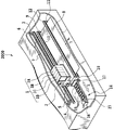
図4は、本発明を適用可能なインクジェット記録装置の要部の模式的斜視図である。
(Configuration of recording device)
FIG. 4 is a schematic perspective view of a main part of an ink jet recording apparatus to which the present invention is applicable.
図4において、複数(4個)のヘッドカートリッジ1A,1B,1C,1Dがキャリッジ2に交換可能に搭載されている。カートリッジ1A〜1Dのそれぞれには、インクを吐出可能な記録ヘッドと、その記録ヘッドにインクを供給するインクタンク部と、記録ヘッドを駆動する信号を受けるためのコネクターと、が含まれている。以下の説明では、ヘッドカートリッジ1A〜1Dの全体または任意の1つを記録ヘッド1ともいう。
In FIG. 4, a plurality (four) of
ヘッドカートリッジ1A〜1Dは、それぞれ異なる色のインクを用いて記録をするためのものであり、それらのインクタンク部には、例えばシアン(C)、マゼンタ(M)、イエロー(Y)、黒(Bk)などの異なるインクが収納されている。各ヘッドカートリッジ1A〜1Dはキャリッジ2に交換可能に搭載され、そのキャリッジ2には、カートリッジ1A〜1D側のコネクターを介して各記録ヘッドに駆動信号等を伝達するためのコネクタホルダ(電気接続部)が設けられている。
The
キャリッジ2は、装置本体に設置されたガイドシャフト3によって、矢印Xの主走査方向に移動可能にガイドされている。このキャリッジ2は、主走査モータ4により、モータプーリ5、従動プーリ6、及びタイミングベルト7を介して駆動され、その位置及び移動が制御される。用紙やプラスチック薄板等の被記録媒体8は、2組の搬送ローラ9,10及び11,12の回転により、記録ヘッド1の吐出口面と対向する位置(記録部)を通して搬送(紙送り)される。記録ヘッド1の吐出口面はノズルを構成する吐出口が形成される面であり、記録ヘッド1は、その吐出口からインク滴の吐出が可能である。被記録媒体8は、記録部において平坦な記録面を形成するように、その裏面がプラテン(不図示)により支持される。キャリッジ2に搭載された各カートリッジにおける記録ヘッド1の吐出口面は、キャリッジ2から下方へ突出して、2組の搬送ローラ9,10及び11,12の間の被記録媒体8の記録面と対向する。
The
本例の記録ヘッド1は、熱エネルギーを利用してインクを吐出するインクジェット記録ヘッドであり、熱エネルギーを発生するための電気熱変換体(ヒーター)を備えている。すなわち、電気熱変換体から発生する熱エネルギーによってノズル内のインクに膜沸騰を生じさせ、そのときの気泡の成長、収縮によって生じる圧力変化を利用して、吐出口からインク滴を吐出させる。記録ヘッド1におけるインクの吐出方式は何ら特定されず、例えば、ピエゾ素子などを用いてインクを吐出する方式であってもよい。
The
図5は、本例の記録ヘッド1におけるインク吐出部13の主要部の模式的斜視図である。図5において、被記録媒体8と所定の隙間(約0.5〜2[mm]程度)をおいて対面する吐出口面21には、所定のピッチで複数の吐出口22が形成されている。インクが供給される共通液室23と各吐出口22とは各流路24によって連通され、インクの吐出エネルギーを発生するための電気熱変換体(発熱抵抗体など)25が各流路24の壁面に沿って配設されている。記録ヘッド1は、各吐出口22がキャリッジ2の走査方向(矢印X方向)と交差する方向に列状に並ぶように、キャリッジ2に搭載される。画像信号または吐出信号に基づいて電気熱変換体25を駆動(通電)することにより、それに対応する流路24内のインクを膜沸騰させ、そのときに発生する圧力を利用して吐出口22からインク滴を吐出させることができる。
FIG. 5 is a schematic perspective view of the main part of the
(記録システムの構成)
図6は、本発明の適用対象の一例である記録システムのハードウェア構成を示すブロック図である。本実施形態に係るシステムは、概して、記録データの生成、及びその生成のためのUI(ユーザインタフェース)設定等を行うホスト装置1000と、その記録データに基づいて被記録媒体に画像を形成するインクジェット記録装置2000と、によって構成される。
(Configuration of recording system)
FIG. 6 is a block diagram showing a hardware configuration of a recording system that is an example to which the present invention is applied. The system according to the present embodiment generally includes a
ホスト装置(ホストコンピュータ)1000は、CPU1001、ROM1002、RAM1003、システムバス1004、種々の入出力機器のためのI/Oコントローラ(CRTC,HDC,FDCなど)1005、外部インタフェース(I/F)1006、ハードディスクドライブ(HDD)やフロッピー(登録商標)ディスクドライブ(FDD)などの外部記憶装置(HDD/FDD)1007、リアルタイムクロック(RTC)1008、CRT1009、およびキーボードやマウスなどの入力装置(KeyBoard/Mouse)1010等を備える。
A host device (host computer) 1000 includes a
CPU1001は、外部記憶装置1007等からRAM1003に読み込んだアプリケーションプログラムや、通信プログラム、プリンタドライバ、オペレーティングシステム(OS)等に基づいて動作する。電源投入時は、ROM1002によりブートし、外部記憶装置1007等からOSをRAM1003にロードした後、アプリケーションプログラムやドライバソフトウェア等も同様にロードすることにより、システムとして機能する。外部I/F1006は、RAM1003や外部記憶装置1007(HDD)内にスプールした記録データを順次記録装置2000に送信する。入力装置1010は、I/Oコントローラ1005を介して、ユーザからの指示データをホストコンピュータ内に取り込む。RTC1008は、システム時間を計時するためのものであり、I/Oコントローラ1005を介して時間情報の取得や設定等を行う。CRT1009は表示装置であり、I/Oコントローラ1005内のCRTCにより制御される。これらのCRT1009および入力装置1010のブロックにより、ユーザインタフェースが構成される。
The
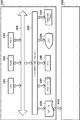
図7は、図6のインクジェット記録装置2000における制御系のブロック構成図である。
FIG. 7 is a block diagram of a control system in the
図7においてコントローラ100は主制御部であり、例えば、マイクロコンピュータ形態のCPU101、プログラムや所要のテーブルその他の固定データを格納したROM103、記録データを展開する領域や作業用の領域等を設けたRAM105、および後述する図13に示される記録制御部1010を有する。記録データ、その他のコマンド、ステータス信号等は、不図示のインタフェース(I/F)を介して、前述したホスト装置1000とコントローラ100との間にて送受信される。
In FIG. 7, a
操作部120は操作者による指示入力を受容するスイッチ群であり、電源スイッチ122、プリント開始を指示するためのスイッチ124、吸引回復の起動を指示するための回復スイッチ126等を含む。ヘッドドライバ140は、記録データ等に応じて、記録ヘッド1の電気熱変換体(以下、「吐出ヒータ」ともいう)25を駆動するドライバである。ヘッドドライバ140は、記録データを吐出ヒータ25の位置に対応させて整列させるシフトレジスタ、記録データを適宜のタイミングでラッチするラッチ回路、駆動タイミング信号に同期して吐出ヒータ25を作動させる論理回路素子の他、インクドットの形成位置を合わせるために駆動タイミング(吐出タイミング)を適切に設定するタイミング設定部等を有する。
The operation unit 120 is a switch group that receives an instruction input from an operator, and includes a
本例においては、記録ヘッド1にサブヒータ142が設けられている。サブヒータ142は、記録ヘッド1におけるインクの吐出特性を安定させるための温度調整を行うものであり、例えば、吐出ヒータ25と同時に記録ヘッド1の基板上に形成される形態、または記録ヘッドの本体ないしはヘッドカートリッジに取り付けられる形態とすることができる。
In this example, a
モータ・ドライバ150は、キャリッジ2を主走査方向に移動させるための主走査モータ4を駆動するドライバである。モータ・ドライバ160は、被記録媒体8を副走査方向に搬送するための副走査モータ162を駆動するドライバである。
The
図8は、本発明の適用対象の一例である記録システムを記録データの流れに沿って示した機能ブロック図である。本実施形態の記録装置2000は、前述したように、シアン、マゼンタ、イエローおよびブラックの4色のインクを用いて記録を行うものである。
FIG. 8 is a functional block diagram showing a recording system as an example of an application target of the present invention along the flow of recording data. As described above, the
ホスト装置1000のオペレーティングシステムで動作するプログラムとしては、アプリケーションやプリンタドライバがある。アプリケーションJ0001は、記録装置2000によって記録する記録データの作成処理を実行する。この記録データ、もしくは、その編集等がなされる前のデータは、種々の媒体を介してパーソナルコンピュータ(PC)形態のホスト装置1000に取り込むことができる。本例のPC形態のホスト装置1000は、デジタルカメラで撮像した例えばJPEG形式の画像データを、CFカードを介して取り込むことができる。また、スキャナで読み取った例えばTIFF形式の画像データや、CD−ROMに格納される画像データをも取り込むことができる。さらには、インターネットを介してWEB上のデータを取り込むこともできる。これらの取り込まれたデータは、ホスト装置1000のモニタに表示され、アプリケーションJ0001を介して編集、加工等がなされることによって、例えばsRGB規格の記録データR、G、Bが作成される。そして記録の指示に応じて、この記録データがプリンタドライバに渡される。
Examples of programs that operate on the operating system of the
本実施形態のプリンタドライバは、前段処理J0002、後段処理J0003、γ補正J0004、ハーフトーニングJ0005、および印刷データ作成J0006の処理部を有している。前段処理J0002は、色域(Gamut)のマッピングを行う処理である。 The printer driver of the present embodiment includes processing units for pre-processing J0002, post-processing J0003, γ correction J0004, halftoning J0005, and print data creation J0006. The pre-stage process J0002 is a process for mapping a color gamut.
本実施形態の前段処理J0002は、3次元LUTと補間演算を併用して、8ビットの画像データR、G、Bを記録装置2000の色域内のデータR、G、Bにデータ変換する。3次元LUTは、sRGB規格の画像データR、G、Bによって再現される色域を本プリントシステムの記録装置2000によって再現される色域内に写像する関係を内容とするルックアップテーブルである。
The pre-stage process J0002 of the present embodiment converts 8-bit image data R, G, and B into data R, G, and B in the color gamut of the
後段処理J0003は、前段処理J0002によって色域のマッピングがなされたデータR、G、Bに基づき、このデータが表す色を再現するインク毎の分解データを求める処理である。本例においては、イエロー、マゼンタ、シアン、ブラックのインク色毎、さらにシアンおよびマゼンタのインク色に関してはドットサイズ毎の分解データ、つまり分解データY、M、C、K、SC、SMを求める。Y,M,C,Kは、後述するように、イエロー、マゼンタ、シアン、ブラックのインクによって形成される大ドット用の分解データであり、またSCおよびSMは、後述するように、シアンおよびマゼンタのインクによって形成される小ドット用の分解データである。本実施形態の後段処理J0003では、前段処理J0002と同様に3次元LUTと補間演算を併用する。 The post-stage process J0003 is a process for obtaining the separation data for each ink that reproduces the color represented by this data based on the data R, G, and B on which the color gamut is mapped by the pre-stage process J0002. In this example, separation data for each dot size, that is, separation data Y, M, C, K, SC, and SM is obtained for each ink color of yellow, magenta, cyan, and black, and for cyan and magenta ink colors. Y, M, C, and K are separation data for large dots formed by yellow, magenta, cyan, and black ink, as will be described later, and SC and SM are cyan and magenta, as will be described later. This is the decomposition data for small dots formed by the ink. In the latter stage processing J0003 of the present embodiment, the three-dimensional LUT and the interpolation calculation are used together as in the former stage processing J0002.
γ補正J0004は、後段処理J0003によって求められたインク色およびドットサイズ毎の分解データのそれぞれに対して、階調値変換を行う。具体的には、記録装置2000において用いられる各色のインクの階調特性に応じた1次元LUTを用いて、インク色およびドットサイズに対応した分解データを記録装置2000の階調特性に線形的に対応付けるように変換する。
The γ correction J0004 performs gradation value conversion for each of the ink color and the separation data for each dot size obtained by the post-processing J0003. Specifically, by using a one-dimensional LUT corresponding to the gradation characteristics of each color ink used in the
ハーフトーニングJ0005は、8ビットの色分解データY、M、C、K、SC、SMのそれぞれを量子化して、2ビットのデータに変換する。本実施形態では、誤差拡散法を用いて8ビットデータを2ビットデータに変換する。この2ビットデータは、後述する記録装置2000のドット配置パターン化処理における配置パターンを示すためのインデックスデータである。記録情報作成処理J0006は、その2ビットのインデックスデータを内容とする記録データに記録制御情報を加えて記録情報を作成する。
Halftoning J0005 quantizes each of 8-bit color separation data Y, M, C, K, SC, and SM and converts the data into 2-bit data. In this embodiment, 8-bit data is converted into 2-bit data using an error diffusion method. This 2-bit data is index data for indicating an arrangement pattern in a dot arrangement patterning process of the
なお、上述したアプリケーションおよびプリンタドライバの処理は、それらのプログラムに従ってCPU1001(図6参照)により行われる。そのプログラムは、ROM1002もしくはハードディスクなどの外部記憶装置1007から読み出されて用いられ、また、そのプログラムに従う処理の実行に際しては、RAM1003がワークエリアとして用いられる。
Note that the processing of the application and printer driver described above is performed by the CPU 1001 (see FIG. 6) according to these programs. The program is read from the
記録装置2000は、データ処理に関しては、ドット配置パターン化処理J0007とマスクデータ変換処理J0008を行う。ドット配置パターン化処理J0007は、実際の記録画像に対応する画素毎に、記録データである2ビットのインデックスデータ(階調値情報)に対応したドット配置パターンに従って、ドット配置を行う。このように、2ビットデータで表現される各画素に対して、その画素の階調値に対応したドット配置パターンを割当てることにより、画素内の複数のエリア毎にドットのオン・オフ、つまりドットを形成するか否かが定義されて、1画素内の各エリアに対して「1」または「0」の吐出データが配置される。
The
このようにして得られる1ビットの吐出データは、マスクデータ変換処理J0008によってマスク処理がなされる。すなわち、記録ヘッド1の記録走査毎の吐出データを生成する。所定領域の記録画像を記録ヘッド1の複数回の走査によって完成させるマルチパス記録においては、それぞれの走査に対応したマスクを用いた処理によって、それぞれの走査毎の吐出データを生成する。走査毎の吐出データY、M、C、K、SC、SMは適切なタイミングでヘッド駆動回路(ヘッドドライバ)140に送られ、それらの吐出データに基づいて、記録へッド1が駆動されてインクが吐出される。
The 1-bit ejection data obtained in this way is subjected to a mask process by a mask data conversion process J0008. That is, ejection data for each recording scan of the
なお、記録装置2000における上述のドット配置パターン化処理J0007やマスクデータ変換処理J0008は、記録装置2000の制御部を構成するCPU101(図7参照)の制御下において、専用のハードウェア回路を用いて実行される。これらの処理は、プログラムに従ってCPU101により実行されてもよく、または、パーソナルコンピュータ(PC)形態のホスト装置100において例えばプリンタドライバによって実行されてもよい。本発明を適用する上において、これら処理の形態が問われないことは、以下の説明からも明らかである。
Note that the above-described dot arrangement patterning process J0007 and mask data conversion process J0008 in the
また、本明細書において「画素」とは、階調表現できる最小単位のことであり、複数ビットの多値データの画像処理(上述した前段処理、後段処理、γ補正、ハーフトーニング等の処理)の対象となる最小単位である。また、ハーフトーニング処理において、1つの画素はm×n(例えば2×2)のマスで構成されるパターンに対応し、この1画素内の各マスは「エリア」と定義する。この「エリア」は、ドットのオン・オフが定義される最小単位である。これに関連して、上述した前段処理、後段処理、γ補正にいう「画像データ」は、処理対象である画素の集合を表しており、各画素は、本実施形態では8ビットの階調値を内容とするデータである。また、上述したハーフトーニングにいう「画素データ」は、処理対象である画素データそのものを表しており、本実施形態のハーフトーニングでは、上記の8ビットの階調値を内容とする画素データが2ビットの階調値を内容とする画素データ(インデックスデータ)に変換される。 Further, in this specification, “pixel” is a minimum unit that can express gradation, and image processing of multi-bit multi-bit data (processing such as the above-described pre-processing, post-processing, γ correction, halftoning, etc.) This is the smallest unit that is subject to In the halftoning process, one pixel corresponds to a pattern composed of m × n (for example, 2 × 2) cells, and each cell in one pixel is defined as an “area”. This “area” is a minimum unit in which dot on / off is defined. In this connection, the “image data” referred to in the above-described pre-stage processing, post-stage processing, and γ correction represents a set of pixels to be processed, and each pixel has an 8-bit gradation value in this embodiment. Is the data. Further, the “pixel data” referred to in the above halftoning represents the pixel data itself to be processed, and in the halftoning of the present embodiment, there are two pieces of pixel data containing the above 8-bit gradation value. It is converted into pixel data (index data) containing bit gradation values.
(気流制御)
図9、図10、図11(a),(b)は、記録ヘッド1の移動速度に応じた気流制御の手法について説明する図である。ここでは、記録媒体上の所定領域に記録すべき画像を記録ヘッド1の4回の走査によって完成させる、いわゆる4パス記録の例をとって説明する。
(Airflow control)
FIGS. 9, 10, 11 (a) and 11 (b) are diagrams for explaining a method of airflow control according to the moving speed of the
図9は、本例において用いる記録ヘッドの説明図であり、シアン(C),マゼンタ(M),イエロー(Y),ブラック(K)のインクを吐出するためのノズル列が形成されている。シアンインク吐出用のノズル列としては、大ドット形成用のノズル列C1,C2と、小ドット形成用のノズル列C3,C4が形成されており、それらは主走査方向において対称的となるように配列されている。ノズル列C1,C3は共通液室を挟んで隣接し、またノズル列C2,C4は共通液室を挟んで隣接する。同様に、マゼンタインク吐出用のノズル列として、大ドット形成用のノズル列M1,M2と、小ドット形成用のノズル列M3,M4が形成されている。また、イエローインク吐出用のノズル列としては大ドット形成用のノズル列Y1,Y2が形成され、同様に、ブラックインク吐出用のノズル列として大ドット形成用のノズル列K1,K2が形成されている。 FIG. 9 is an explanatory diagram of the recording head used in this example, in which nozzle arrays for ejecting cyan (C), magenta (M), yellow (Y), and black (K) inks are formed. As the nozzle rows for cyan ink ejection, nozzle rows C1 and C2 for forming large dots and nozzle rows C3 and C4 for forming small dots are formed so that they are symmetrical in the main scanning direction. It is arranged. The nozzle rows C1 and C3 are adjacent to each other across the common liquid chamber, and the nozzle rows C2 and C4 are adjacent to each other across the common liquid chamber. Similarly, nozzle rows M1 and M2 for forming large dots and nozzle rows M3 and M4 for forming small dots are formed as nozzle rows for discharging magenta ink. In addition, nozzle rows Y1 and Y2 for forming large dots are formed as nozzle rows for discharging yellow ink, and nozzle rows K1 and K2 for forming large dots are similarly formed as nozzle rows for discharging black ink. Yes.
このような記録ヘッドを用いた場合には、矢印X(X1,X2)の主走査方向において双方向記録を実施して、カラー画像を記録することができる。以下、矢印X1を往路方向、矢印X2を復路方向ともいう。このような双方向記録において、例えば、往路記録時にノズル列C1,C3,M1,M3,K1,K2,Y1,Y2を用い、復路記録時にノズル列C2,C4,M2,M4,K1,K2,Y1,Y2を用いることにより、それぞれの記録時におけるインクの打ち込み順序を合わせることができる。 When such a recording head is used, a color image can be recorded by performing bidirectional recording in the main scanning direction indicated by an arrow X (X1, X2). Hereinafter, the arrow X1 is also referred to as the forward direction, and the arrow X2 is also referred to as the return direction. In such bidirectional recording, for example, nozzle rows C1, C3, M1, M3, K1, K2, Y1, and Y2 are used during forward printing, and nozzle rows C2, C4, M2, M4, K1, K2, and so on during backward printing. By using Y1 and Y2, it is possible to match the order of ink ejection at the time of recording.
本例においては、往路記録時および復路記録時に全てのノズル列を用いて記録する。これにより、記録速度を高めることができる。その際には、略等しい量の同色インク滴を吐出する対のノズル列(大ドット形成用の対のノズル列、または小ドット形成用の対のノズル列)に対して、記録データをほぼ等しく割り振り(振りまき処理)、それらの対のノズル列の一方に記録データが偏らないようにする。このように対のノズル列を均等に使用することにより、インクの打ち込み順序が異なる部分を均等に分散させて、色ムラの発生を抑制することができると共に、それぞれのノズル内の吐出ヒータに掛かる負担を分散させることができる。例えば、シアンインクを比較的多く吐出させる大ドット形成用の記録データは、ノズル列C1,C2に均等に振りまくように展開し、シアンインクを比較的少なく吐出させる小ドット形成用の記録データは、ノズル列C3,C4に均等に振りまくように展開する。 In this example, recording is performed using all nozzle rows during forward recording and backward recording. Thereby, the recording speed can be increased. In that case, the recording data is almost equal to a pair of nozzle rows (a pair of nozzles for forming a large dot or a pair of nozzles for forming a small dot) that eject ink droplets of substantially the same amount of the same color. Allocation (sprinkling process) is performed so that the recording data is not biased to one of the pair of nozzle rows. By using the pair of nozzle rows evenly in this way, it is possible to evenly distribute portions with different ink ejection orders, thereby suppressing the occurrence of color unevenness and applying to the discharge heaters in the respective nozzles. The burden can be distributed. For example, the recording data for forming large dots for ejecting a relatively large amount of cyan ink is developed so as to be distributed evenly to the nozzle rows C1 and C2, and the recording data for forming small dots for ejecting a relatively small amount of cyan ink is: The nozzle rows C3 and C4 are spread out evenly.
本例においては、大ドットを形成するノズル列を第1ノズル列L1、小ドットを形成するノズル列を第2ノズル列L2とする。ノズル列の間の距離が小さければ小さいほど、それらのノズル間における気流の影響が大きくなるため、共通液室を挟むように配されたノズル列の間における気流の影響は大きい。また、インクの吐出量が少ないノズル列、つまり運動エネルギーが小さい小インク滴を吐出するノズル列に対しては、気流の影響度が大きくなる。さらに、記録ヘッドの移動速度が高いほど、気流の影響度は大きくなる。 In this example, a nozzle row that forms large dots is a first nozzle row L1, and a nozzle row that forms small dots is a second nozzle row L2. The smaller the distance between the nozzle rows, the greater the influence of the airflow between the nozzles, and the greater the influence of the airflow between the nozzle rows arranged so as to sandwich the common liquid chamber. Further, the influence of the airflow becomes large for the nozzle row having a small ink discharge amount, that is, the nozzle row for discharging a small ink droplet having a small kinetic energy. Furthermore, the higher the moving speed of the recording head, the greater the influence of the airflow.
本例においては、図10のように、4パス記録において記録ヘッドの移動速度が異なる場合に、第1ノズル列L1と第2ノズル列L2との間における気流の影響を抑制するための気流制御ライン1401,1402,1403を実験的に得た。
In this example, as shown in FIG. 10, when the moving speed of the recording head is different in four-pass printing, the air flow control for suppressing the influence of the air flow between the first nozzle row L1 and the second nozzle row L2.
図10において、縦軸および横軸は1画素当たりにおけるドットの形成数である。また図9のように、同一のラスター(R0〜R15)上に位置する大ドット形成用のノズルは各インク色において1つずつであり、同様に、同一のラスター(R0〜R15)上に位置する小ドット形成用のノズルは各インク色において1つずつである。そのため、例えば、ノズル列C1によって1画素内に形成される大ドットは、図11(a)のように偶数ラスター上における2ドットが最大となり、またノズル列C3によって1画素内に形成される小ドットは、図11(b)のように奇数ラスター上における2ドットが最大となる。したがってシアンインク吐出用のノズル列に関しては、図10における横軸は、第1ノズル列L1としてのノズル列C1,C2による1画素内の合計の形成ドット数(最大数4)であり、図10における縦軸は、第2ノズル列L2としてのノズル列C3,C4による1画素内の合計の形成ドット数(最大数4)である。大ドット形成用の記録データはノズル列C1,C2に対して均等に振り分けられ、また小ドット形成用の記録データはノズル列C3,C4に対して均等に振り分けられる。 In FIG. 10, the vertical and horizontal axes represent the number of dots formed per pixel. Also, as shown in FIG. 9, one large dot forming nozzle is positioned on the same raster (R0 to R15), and similarly, the nozzle is positioned on the same raster (R0 to R15). There is one small dot forming nozzle for each ink color. Therefore, for example, the large dots formed in one pixel by the nozzle row C1 are the largest two dots on the even raster as shown in FIG. 11A, and the small dots formed in one pixel by the nozzle row C3. As shown in FIG. 11B, the maximum number of dots is 2 dots on the odd raster. Therefore, regarding the nozzle row for cyan ink ejection, the horizontal axis in FIG. 10 is the total number of dots formed in one pixel (maximum number 4) by the nozzle rows C1 and C2 as the first nozzle row L1, and FIG. The vertical axis represents the total number of dots formed in one pixel (maximum number 4) by the nozzle rows C3 and C4 as the second nozzle row L2. The recording data for forming large dots is equally distributed to the nozzle rows C1 and C2, and the recording data for forming small dots is equally distributed to the nozzle rows C3 and C4.
気流制御ライン1401,1402,1403は、1画素内において、第1ノズル列によって形成されるドット数と、第2ノズル列によって形成されるドット数と、比率を表すことになる。
The
まず、気流制御ライン1401に基づいて、第1ノズル列と第2ノズル列によって形成される1画素当たりのドット数について考察する。気流制御ライン1401の上側の領域は、インクの吐出に伴う気流の影響が大きく、高品位の画像の記録が難しいNG領域である。一方、第1ノズル列と第2ノズル列による形成ドット数の合計が少ない領域、つまり気流制御ライン1401の下側の領域は、インクの吐出に伴う気流の影響が小さく、高品位の画像の記録が可能なOK領域である。記録制御するときには、第1および第2ノズル列によって形成されるドット数がOK領域内となるような記録データに基づいて、記録しなければならない。
First, based on the
3本の気流制御ライン1401,1402,1403は、4パス記録において記録ヘッドの移動速度が異なる場合の気流制御ラインである。記録ヘッドの移動速度が35[インチ/秒]のときには、気流制御ライン1401のOK領域内においてドットを形成するような記録データを生成し、その記録データに基づいて画像を記録する。また、記録ヘッドの移動速度が25[インチ/秒]のときには、気流制御ライン1402のOK領域内においてドットを形成するような記録データを生成し、その記録データに基づいて画像を記録する。また、記録ヘッドの移動速度が12.5[インチ/秒]のときには、気流制御ライン1403のOK領域内においてドットを形成するような記録データを生成し、その記録データに基づいて画像を記録する。記録ヘッドの移動速度が遅いほど気流の影響度が小さくなるため、その移動速度が遅いほど気流制御ラインは高めになり、OK領域が広くなる。このように、記録ヘッドの移動速度に応じたOK領域内においてドットを形成するように記録データを生成し、その記録データに基づいて画像を記録する。したがって、記録ヘッドの移動速度の如何に拘わらず、気流の影響のない記録制御の実現が可能となる。
The three air
図12は、大ドット形成用の記録データと小ドット形成用の記録データの構成例の説明図であり、それらのデータは、互い独立した2ビットのデータ形式となっている。大ドット形成用の記録データがレベル1のときは1画素に大ドットが1つ形成され、同様に、小ドット形成用の記録データがレベル1のときは1画素に小ドットが1つ形成される。その場合、前者のレベル1の記録データは、大ドット形成用の対のノズル列(例えば、シアンインクの場合にはノズル列C1,C2)に対して均等に振りまかれ、後者のレベル1の記録データは、小ドット形成用の対のノズル列(シアンインクの場合にはノズル列C3,C4)に均等に振りまかれる。
FIG. 12 is an explanatory diagram of a configuration example of recording data for forming large dots and recording data for forming small dots, and these data are in a 2-bit data format independent of each other. When the recording data for forming large dots is
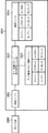
図13は、このような記録データの振りまき処理を説明するためのブロック構成図である。 FIG. 13 is a block diagram for explaining such a recording data distribution process.
インクジェット記録装置2000の記録制御部1010において、受信バッファ1011は、ホスト装置1000から2ビットに量子化された記録データを受信し、ドット配置パターン格納ユニット1012はドット配置パターンを格納する。ドット配置パターン割り付けモジュール1013は、前述した図8のドット配置パターン化処理を実行するものであり、格納ユニット1012に格納されたドット配置バターンを用いて、受信バッファ1011内の記録データにドット配置パターンを割り付ける。展開バッファ(プリントバッファ)1014は、モジュール1013によって割り付けられたドット配置パターンにより、記録データを展開する。モジュール1013は、ROM103(図7参照)に格納されてCPU101(図7参照)によって実行されるソフトウェアモジュールである。受信バッファ1011、格納ユニット1012、および展開バッファ1014は、DRAMの所定のアドレス領域に用意する。
In the
格納ユニット1002には、ドット配置パターンが予め番号を割り付けて格納されている。そのドット配置パターンは、図12のように、大きさが異なるドット毎の記録データ(レベル0〜3の量子化データ)が取り得るドット配置パターンである。そして、それらの中から選択したパターンを展開バッファに1004に展開し、その展開したパターンにしたがってドットが形成される。図13において、大シアンはシアンインクによる大ドット形成用のパターン、小シアンはシアンインクによる小ドット形成用のパターン、大マゼンタはマゼンタインクによる大ドット形成用のパターン、小マゼンタはマゼンタインクによる小ドット形成用のパターン、大イエローはイエローインクによる大ドット形成用のパターン、大ブラックはブラックインクによる大ドット形成用のパターンである。
In the
図14は、ドット配置パターン割り付けモジュール1003によるデータ展開処理を説明するためのフローチャートである。
FIG. 14 is a flowchart for explaining data expansion processing by the dot arrangement
まず、ホスト装置1000から転送された記録データ(2ビットの量子化データ)を受信し、その記録データを受信バッファ1001に格納する(ステップS1)。そして、その格納した記録データの中から1画素分の記録データを読み出し(ステップS2)、その記録データのレベル(0〜3)に対応するドット配置パターンを選択して、そのパターンを展開バッファ1005に展開する(ステップS3)。同一レベルの記録データに対してドット配置パターンが2つある場合には、それらのうちのいずれかを選択して展開することになる。その際には、それらの同一レベルの2つのドット配置パターンを交互に割り当てる。本例の場合、レベル1の記録データによってシアンインクの小ドットを形成するときには、図12のような2つのパターンを交互に割り当てて、ノズル列C3,C4に対して記録データを均等に振りまく。そして、受信バッファ1001に格納した記録データの全画素について、展開バッファ1004への展開が終了したか否かを判定し(ステップS4)、それが終了していなければステップS2に戻り、それが終了したときにはデータの展開処理を終了する。
First, recording data (2-bit quantized data) transferred from the
(記録データの生成)
図15(a),(b),(c)および図16(a),(b),(c)は、図9のように、大ドット形成用のノズル列と小ドット形成用のノズル列に対応する記録データの生成方法の具体的な説明図である。
(Generation of recorded data)
FIGS. 15A, 15B and 16C and FIGS. 16A, 16B and 16C show a nozzle array for forming large dots and a nozzle array for forming small dots as shown in FIG. FIG. 6 is a specific explanatory diagram of a method for generating recording data corresponding to the above.
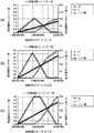
本実施形態においては、記録画像の各階調レベルに関して、階調性を維持しつつ、気流制御ラインのOK領域内となる記録データを生成する。本例においては、図15(a),(b),(c)のような後段処理J0003(図8参照)でのデータ変換処理を含む一連のデータ処理を介して、最終的に、各ノズル列に対応した記録データを生成する。後段処理J0003は、前述したように、R,G,Bに関して8ビットずつの輝度データ(後段処理入力データ)を入力し、8ビットずつの色分解データC,M,Y,K,SC,SM(後段処理出力データ)に変換する。 In the present embodiment, for each gradation level of the recorded image, recording data that is within the OK region of the airflow control line is generated while maintaining gradation. In this example, each nozzle is finally obtained through a series of data processing including data conversion processing in the subsequent stage processing J0003 (see FIG. 8) as shown in FIGS. 15 (a), 15 (b), and 15 (c). Record data corresponding to the column is generated. As described above, the post-stage processing J0003 receives 8-bit luminance data (post-stage processing input data) for R, G, and B, and outputs 8-bit color separation data C, M, Y, K, SC, SM. Convert to (post-processing output data).
図15(a),(b),(c)は、シアンインクによる大ドット形成用のCデータと、シアンインクによる小ドット形成用のSCデータと、に関しての生成方法を代表して説明するための図である。それらのシアンインクによる大ドットと小ドットは、互いに隣接するノズル列(図9中のノズル列C1(L1)とC3(L2)、またはC2(L1)とC4(L2))を用いて形成される。また、これらの図15(a),(b),(c)においては、説明の便宜上、R,G,Bの8ビットずつのデータの内、GおよびBデータを(255)に固定した。したがって、これらの図の横軸つまりR,G,Bに関しての後段処理入力データ(R,G,B)は、GおよびBデータが(255)のときのRデータの変化(色相の変化)を示している。要するに、横軸は、白(255,255,255)から最大濃度のシアン(0,255,255)に至る範囲を示している。一方、これらの図の縦軸は、8ビットの後段処理出力データ(C,SC)の値を示している。また、後段処理J0003によるデータ変換の仕方は、記録ヘッドの移動速度に応じて異なる。本例の場合は、記録ヘッドの移動速度が35[インチ/秒]、25[インチ/秒]、および12.5[インチ/秒]のときに、それぞれ図15(a),(b),(c)のようにデータ変換を行う。 FIGS. 15A, 15B, and 15C are representatively described with respect to generation methods for C data for forming large dots using cyan ink and SC data for forming small dots using cyan ink. FIG. These large and small dots formed by cyan ink are formed using nozzle rows adjacent to each other (nozzle rows C1 (L1) and C3 (L2) in FIG. 9 or C2 (L1) and C4 (L2)). The In FIGS. 15A, 15B, and 15C, for convenience of explanation, G and B data are fixed to (255) among 8-bit data of R, G, and B. Therefore, the post-processing input data (R, G, B) with respect to the horizontal axes of these drawings, that is, R, G, B, represents the change in R data (hue change) when the G and B data are (255). Show. In short, the horizontal axis shows the range from white (255, 255, 255) to the maximum density of cyan (0, 255, 255). On the other hand, the vertical axis in these figures indicates the value of 8-bit post-processing output data (C, SC). Further, the method of data conversion by the post-processing J0003 differs depending on the moving speed of the recording head. In the case of this example, when the moving speed of the recording head is 35 [inch / second], 25 [inch / second], and 12.5 [inch / second], FIGS. Data conversion is performed as in (c).
図15(a)は、記録ヘッドの移動速度が最速の35[インチ/秒]である記録モードが指定された場合に行われる後段処理についての説明図である。図15(a)のように、後段処理入力データが(255、255、255)〜(160,255,255)程度の範囲内の場合、小シアンドットだけで画像形成を行うようにSCデータだけを出力する。その際、小シアンドットの形成数が徐々に増加するように、SCデータを出力する。後段処理入力データが(160,255,255)になったとき、SCデータの出力値は最大(約128)となる。この最大出力値(128)のときの小ドット形成数は、図16(a)のように「2」となるが、この「2」は図10の気流制御ライン1401より下側に位置している。従って、気流問題は発生しない。
FIG. 15A is an explanatory diagram of the subsequent processing that is performed when the recording mode in which the moving speed of the recording head is 35 [inch / second] is designated. As shown in FIG. 15A, when the post-process input data is in the range of (255, 255, 255) to (160, 255, 255), only the SC data is formed so that the image is formed with only small cyan dots. Is output. At this time, SC data is output so that the number of small cyan dots formed gradually increases. When the post-processing input data becomes (160, 255, 255), the output value of the SC data becomes the maximum (about 128). The number of small dots formed at the maximum output value (128) is “2” as shown in FIG. 16A. This “2” is located below the air
次いで、図15(a)において後段処理入力データが(160,255,255)〜(44、255,255)程度の範囲内の場合には、大シアンドットと小シアンドットで画像形成を行うようにCデータとSCデータの両方を出力する。その際、小シアンドットの形成数が徐々に減少し、且つ大シアンドットの形成数が徐々に増加するように、CデータおよびSCデータを出力する。具体的には、後段処理入力データが(92,255,255)になったとき、CデータおよびSCデータの出力値は共に約64程度になり、そのときのドット形成数は共に「1」になる(図16(a)参照)。更に、後段処理入力データが(44,255,255)になったとき、SCデータの出力値は0になり、Cデータの出力値は約100になる。そのときのドット形成数は、小ドットが「0」、大ドットが「1.7」になる(図16(a)参照)。大ドットの形成数と小ドットの形成数が共に「1」となる場合も、小ドットの形成数が「0」且つ大ドットの形成数が「1.7」となる場合も、図10の気流制御ライン1401より下側に位置している。従って、気流問題は発生しない。
Next, in FIG. 15A, when the post-process input data is in the range of about (160, 255, 255) to (44, 255, 255), image formation is performed with large cyan dots and small cyan dots. Output both C data and SC data. At that time, the C data and the SC data are output so that the number of small cyan dots is gradually decreased and the number of large cyan dots is gradually increased. Specifically, when the post-processing input data becomes (92, 255, 255), the output values of C data and SC data are both about 64, and the number of dot formations at that time is both “1”. (See FIG. 16A). Furthermore, when the post-processing input data becomes (44, 255, 255), the output value of SC data becomes 0 and the output value of C data becomes about 100. The number of dots formed at that time is “0” for small dots and “1.7” for large dots (see FIG. 16A). The case where the number of large dots and the number of small dots are both “1”, or the number of small dots is “0” and the number of large dots is “1.7” is shown in FIG. It is located below the
最後に、図15(a)において後段処理入力データが(44,255,255)〜(0、255,255)程度の範囲内の場合には、大シアンドットだけで画像形成を行うように、Cデータだけを出力する。その際、大シアンドットの形成数が徐々に増加するように、Cデータを出力する。後段処理入力データが(0,255,255)になったとき、Cデータの出力値は最大(約128)となる。この最大出力値(128)のときの大ドット形成数は、図16(a)のように「2」となるが、この「2」は図10の気流制御ライン1401より下側に位置している。従って、気流問題は発生しない。
Finally, in FIG. 15A, when the post-processing input data is in the range of (44, 255, 255) to (0, 255, 255), image formation is performed using only large cyan dots. Output only C data. At this time, C data is output so that the number of large cyan dots formed gradually increases. When the post-processing input data becomes (0, 255, 255), the output value of the C data becomes the maximum (about 128). The number of large dots formed at this maximum output value (128) is “2” as shown in FIG. 16A, but this “2” is located below the air
このように記録ヘッドの移動速度が最も速い図15(a)の場合、気流の影響が比較的大きいため、大ドットおよび小ドットの形成数に関する制約を厳しくしている。具体的には、大ドットおよび小ドットの形成数が図10の記録制御ライン1401より下側の狭小なOK領域内に収まるように、大ドット用ノズル列および小ドット用ノズル列に対応する記録データを生成している。こうすることで、記録ヘッドの移動速度が最速の場合の気流影響を抑制している。
In this way, in the case of FIG. 15A where the moving speed of the recording head is the fastest, the influence of the air flow is relatively large, and thus the restrictions on the number of large dots and small dots formed are severe. Specifically, the recording corresponding to the large dot nozzle row and the small dot nozzle row is such that the number of large dots and small dots formed falls within the narrow OK region below the
これに対し、図15(c)は、記録ヘッドの移動速度が最も低い12.5[インチ/秒]の記録モードが指定された場合に行われる後段処理についての説明図である。図15(c)のように、小ドットの形成が許容される後段処理入力データの範囲は、図15(a)に比べて広くなる。つまり、小ドットが使用できる階調範囲が広くなっているので、ハイライト部分の粒状性低減に有利である。また、図15(c)は、図15(a)に比べて、小ドットの最大形成数や大ドットの最大形成数を多くしているため、表現できる濃度域が広い。 On the other hand, FIG. 15C is an explanatory diagram of the subsequent processing that is performed when the recording mode of 12.5 [inches / second] in which the moving speed of the recording head is the lowest is designated. As shown in FIG. 15C, the range of post-processing input data in which the formation of small dots is allowed is wider than that in FIG. That is, since the gradation range in which small dots can be used is widened, it is advantageous for reducing the graininess of the highlight portion. Further, in FIG. 15C, the maximum number of small dots and the maximum number of large dots are increased as compared to FIG.
更に、図15(c)は、図15(a)に比べて、小ドットと大ドットを単位領域内で混在させる場合の大小ドットの最大合計数を多くしている。気流の影響が大きい程、大ドットと小ドットの混在数を制約する必要が高いのであるが、図15(c)は図15(a)の場合に比べて気流の影響が小さいため、上述した制約が小さく、その結果、大ドットと小ドットの最大混在数を多くできる。大ドットと小ドットの最大混在数の許容範囲が広いほど、大ドットの入り始めにおける小ドットの打ち込み量を比較的多く設計できるので、中間調域における大ドットの粒状感を低減できる。また、中間調域から高濃度域においては、インク滴の吐出ヨレに起因する搬送方向のスジが発生しやすい。しかし、大ドットと小ドットの最大混在数を多くすれば、この濃度域において記録に関与するノズル数を増すことが可能となるため、上述したヨレの影響を低減できる。図15(c)の場合は、大ドットおよび小ドットの形成数が図10の記録制御ライン1403より下側に位置するOK領域内に収まるように、大ドット用ノズル列および小ドット用ノズル列に対応する記録データを生成している。 Further, in FIG. 15C, the maximum total number of large and small dots when the small dots and the large dots are mixed in the unit area is increased as compared with FIG. The greater the influence of airflow, the higher the need to restrict the number of mixed large and small dots. However, the influence of the airflow is smaller in FIG. 15C than in the case of FIG. The restrictions are small, and as a result, the maximum number of mixed large dots and small dots can be increased. As the allowable range of the maximum number of large dots and small dots mixed is wider, a relatively large amount of small dots can be designed at the beginning of large dots, so that the granularity of large dots in the halftone region can be reduced. Also, streaks in the transport direction due to ink droplet ejection deviation are likely to occur from the halftone area to the high density area. However, if the maximum number of large dots and small dots mixed is increased, the number of nozzles involved in recording in this density range can be increased, so that the influence of the above-mentioned deviation can be reduced. In the case of FIG. 15C, the large dot nozzle row and the small dot nozzle row so that the number of large dots and small dots formed falls within the OK region located below the recording control line 1403 in FIG. Recording data corresponding to is generated.
これを具体的に説明すると、図15(c)において後段処理入力データが(255、255、255)〜(160,255,255)程度の範囲内の場合、SCデータの出力値を徐々に増加させる。後段処理入力データが(160,255,255)となったとき、SCデータの出力値は最大(約256)となる。この最大出力値(256)のときの小ドット形成数は、図16(c)のように「4」となるが、この「4」は図10の気流制御ライン1403より下側に位置している。従って、気流問題は発生しない。 Specifically, in FIG. 15C, when the post-stage processing input data is in the range of (255, 255, 255) to (160, 255, 255), the output value of the SC data is gradually increased. Let When the post-stage processing input data becomes (160, 255, 255), the output value of the SC data becomes the maximum (about 256). The number of small dots formed at the maximum output value (256) is “4” as shown in FIG. 16C, but this “4” is located below the air flow control line 1403 in FIG. Yes. Therefore, the airflow problem does not occur.
次いで、図15(c)において後段処理入力データが(160、255、255)〜(116,255,255)程度の範囲内の場合、SCデータの出力値を最大(約256)に保ったまま、Cデータを徐々に増加させる。後段処理入力データが(116,255,255)となったとき、図16(c)のように、小ドットの形成数は「4」、大ドットの形成数は「1」となる。このドット数の組合せは、図10の気流制御ライン1403より下側に位置しているため、気流問題は発生しない。 Next, in FIG. 15C, when the post-stage processing input data is in the range of (160, 255, 255) to (116, 255, 255), the output value of the SC data is kept at the maximum (about 256). , C data is gradually increased. When the post-processing input data becomes (116, 255, 255), as shown in FIG. 16C, the number of small dots formed is “4” and the number of large dots formed is “1”. Since the combination of the number of dots is located below the airflow control line 1403 in FIG. 10, no airflow problem occurs.
最後に、図15(c)において後段処理入力データが(116、255、255)〜(0、255、255)程度の範囲内の場合には、SCデータの出力値を徐々に減少させながら、Cデータの出力値を徐々に増加させる。後段処理入力データが(64、255、255)になったとき、SCデータおよびCデータの出力値は共に(約128)となる。このときの小ドット形成数および大ドット形成数は共に「2」となる(図16(c)参照)。このドット数の組合せは、図10の気流制御ライン1403より下側に位置しているため、気流問題は発生しない。また、後段処理入力データが(0,255,255)になったとき、Cデータの出力値は最大(約255)となる。この最大出力値(255)のときの大ドット形成数は、図16(c)のように「4」となるが、この「4」は図10の気流制御ライン1403より下側に位置している。従って、気流問題は発生しない。 Finally, in FIG. 15C, when the post-stage processing input data is within the range of (116, 255, 255) to (0, 255, 255), the output value of the SC data is gradually decreased, The output value of C data is gradually increased. When the post-processing input data becomes (64, 255, 255), the output values of SC data and C data are both (about 128). At this time, the number of small dots and the number of large dots are both “2” (see FIG. 16C). Since the combination of the number of dots is located below the airflow control line 1403 in FIG. 10, no airflow problem occurs. Further, when the post-stage processing input data becomes (0, 255, 255), the output value of the C data becomes the maximum (about 255). The number of large dots formed at this maximum output value (255) is “4” as shown in FIG. 16C, but this “4” is located below the air flow control line 1403 in FIG. Yes. Therefore, the airflow problem does not occur.
このように記録ヘッドの移動速度が最も遅い図15(c)の場合、気流の影響が比較的小さいため、大ドットおよび小ドットの形成数に関する制約を図15(a)に比べて比較的緩くしている。具体的には、大ドットおよび小ドットの形成数が図10の記録制御ライン1403より下側の広大なOK領域内に収まるように、大ドット用ノズル列および小ドット用ノズル列に対応する記録データを生成している。こうすることで、記録ヘッドの移動速度が遅い場合の気流影響を抑制している。 In this way, in the case of FIG. 15C where the moving speed of the recording head is the slowest, since the influence of the airflow is relatively small, the restrictions on the number of large dots and small dots formed are relatively loose compared to FIG. is doing. Specifically, printing corresponding to the large dot nozzle row and the small dot nozzle row so that the number of large dots and small dots formed is within a large OK region below the print control line 1403 in FIG. Data is being generated. By doing so, the influence of the airflow when the moving speed of the recording head is slow is suppressed.
なお、記録ヘッドの移動速度が25[インチ/秒]のときは、図15(b)のように、小ドットの形成が許容される後段処理入力データの範囲は図15(a)よりは広く、図15(c)よりも狭くなる。そのため、小ドットと大ドットを単位領域内で混在させる場合の大小ドットの合計数は、図15(a)に比べて多いが、図15(c)に比べて少ない。この図15(b)の場合は、大ドットおよび小ドットの形成数が図10の記録制御ライン1402より下側に位置するOK領域内に収まるように、大ドット用ノズル列および小ドット用ノズル列に対応する記録データを生成している。
When the moving speed of the recording head is 25 [inch / second], as shown in FIG. 15B, the range of the post-processing input data in which the formation of small dots is allowed is wider than that in FIG. This is narrower than that shown in FIG. Therefore, the total number of large and small dots when a small dot and a large dot are mixed in the unit area is larger than that in FIG. 15A, but smaller than that in FIG. 15C. In the case of FIG. 15B, the large dot nozzle row and the small dot nozzle so that the number of large dots and small dots formed is within the OK region located below the
このような後段処理J0003を含む一連のデータ変換処理により記録データを生成した後、前述したように、その記録データに基づいて記録ヘッドからインクを吐出することにより被記録媒体上に画像を記録する。 After generating recording data by a series of data conversion processes including such post-processing J0003, as described above, an image is recorded on the recording medium by ejecting ink from the recording head based on the recording data. .
図16(a),(b),(c)は、図15(a),(b),(c)の処理を含む一連のデータ変換処理により生成された記録データに基づいて、シアンインクによる大ドットと小ドットを被記録媒体上に形成した場合の説明図である。 FIGS. 16A, 16B, and 16C are based on cyan ink based on print data generated by a series of data conversion processes including the processes of FIGS. 15A, 15B, and 15C. It is explanatory drawing at the time of forming a large dot and a small dot on a to-be-recorded medium.
これらの図の横軸は、図15(a),(b),(c)の横軸と同様に、後段処理J0003における後段処理入力データ(R,G,B)である。また左縦軸は、被記録媒体上の単位記録面積当たりに形成される大ドットと小ドットの数であり、右縦軸は、その単位記録面積に対するシアンインクの合計付与量[pl(ピコリットル)]、つまり大ドットと小ドットを形成するためのシアンインクの合計の打ち込み量である。 The horizontal axis in these figures is the post-stage process input data (R, G, B) in the post-stage process J0003, similarly to the horizontal axes in FIGS. 15 (a), (b), and (c). The left vertical axis represents the number of large dots and small dots formed per unit recording area on the recording medium, and the right vertical axis represents the total amount of cyan ink applied to the unit recording area [pl (picoliters). )], That is, the total amount of cyan ink for forming large dots and small dots.
単位記録面積当たりに形成される大ドットおよび小ドットの数は、記録ヘッドの移動速度に応じて変化する図15(a),(b),(c)の後段処理出力データ(Cデータ,SCデータの出力値)に対応し、結果的に、シアンインクの合計付与量が後段処理入力データに対して直線的に変化する。 The numbers of large dots and small dots formed per unit recording area change in accordance with the moving speed of the recording head. The post-processing output data (C data, SC) shown in FIGS. 15A, 15B, and 15C. As a result, the total amount of cyan ink applied changes linearly with respect to the post-processing input data.
図15(a),(b),(c)に共通することは、後段処理入力データが低濃度領域(例えば、(255,255,255)〜(200,255,255)程度の範囲)のときには、記録画像におけるハイライト部の粒状感を考慮し、小ドットのみによって画像を記録する。その小ドットの形成数は、後段処理入力データが大きくなるにつれて徐々に増やして記録濃度を高める。後段処理入力データが中間調レベル領域以上のときには、必要な記録濃度を得る上においては大ドットを形成する方が効率がよい。仮に、小ドットのみによって画像を記録した場合には、マルチパス記録方式におけるパス数にもよるが、小ドットを形成するための小インク滴が被記録媒体に着弾するときの着弾精度が悪化して、記録画像に濃度むらが生じるおそれがある。そのため、中間調レベル領域では、小ドットと大ドットを混在させて画像を形成する。そのような中間調レベル領域から最大濃度領域にかけては、前述した気流の影響を抑制するために、大ドットの形成用のノズル列と小ドット形成用のノズル列の記録比率を変えて、大ドットを小ドットよりも多く形成する。 What is common to FIGS. 15A, 15B, and 15C is that the post-processing input data is in a low concentration region (for example, a range of (255, 255, 255) to (200, 255, 255)). Sometimes, the image is recorded with only small dots in consideration of the graininess of the highlight portion in the recorded image. The number of small dots formed is gradually increased as the post-processing input data increases to increase the recording density. When the post-processing input data is greater than or equal to the halftone level region, it is more efficient to form large dots in order to obtain the required recording density. If an image is recorded using only small dots, the landing accuracy will deteriorate when small ink droplets for forming small dots land on the recording medium, depending on the number of passes in the multi-pass recording method. As a result, the density unevenness may occur in the recorded image. Therefore, in the halftone level region, an image is formed by mixing small dots and large dots. In such a halftone level area to the maximum density area, in order to suppress the influence of the airflow described above, the recording ratio of the nozzle array for forming large dots and the nozzle array for forming small dots is changed to provide large dots. More than small dots.
本実施形態においては、気流影響、小インク滴の着弾精度、および大ドットを形成し始めるときの記録画像の粒状感を考慮して、上述したように記録データを生成する。このように、記録ヘッドの移動速度によって異なる気流影響を考慮して、記録データを生成することにより、良好な画像を記録ことができる。 また本実施形態においては、記録ヘッドの移動速度に応じて、互いに近接するノズル列から吐出される1画素当たり(単位領域当たり)のインクの吐出量を制御するように、前段処理J1003によって、RGBの入力画像データをC,M,Y,K、SC,SMの記録データに変換する。例えば、記録ヘッドの移動速度毎に、図15(a),(b),(c)のように入出力データを関連付けるテーブルを設けておくことにより、前段処理J1003においては、そのようなテーブルを用いて上述したようなデータ変換をすることができる。 In the present embodiment, recording data is generated as described above in consideration of the influence of airflow, the landing accuracy of small ink droplets, and the granularity of a recorded image when large dots are formed. In this way, a good image can be recorded by generating the recording data in consideration of the influence of the airflow that varies depending on the moving speed of the recording head. In this embodiment, the pre-process J1003 performs RGB processing so as to control the ejection amount of ink per pixel (per unit area) ejected from nozzle rows adjacent to each other according to the moving speed of the recording head. Are converted into C, M, Y, K, SC, SM recording data. For example, by providing a table for associating input / output data as shown in FIGS. 15A, 15B, and 15C for each moving speed of the recording head, such a table is used in the pre-stage processing J1003. Data conversion as described above can be performed.
上述したように、記録ヘッドの移動速度に応じて、近接する複数のノズル列によって形成する単位領域当たり(上述した例では1画素当たり)のドットの形成数を制御すべく、記録データを生成することにより、相互のインク吐出による気流の影響を抑制することができる。近接するノズル列間における気流の影響は、記録ヘッドの移動速度に応じて変化する。そのため、その移動速度に応じた記録データを生成して、それらのノズル列から吐出するインクの吐出量を制御することにより、複数のノズル列を用いた記録に最適な制御を行って高画質の画像を記録することができる。互いに近接するノズル列のインクの吐出量を制御することは、それらのノズル列から吐出されるインク量の比率を制御することにもなる。 As described above, print data is generated in order to control the number of dots formed per unit area (per pixel in the above example) formed by a plurality of adjacent nozzle rows in accordance with the moving speed of the print head. Thereby, the influence of the airflow by mutual ink discharge can be suppressed. The influence of the airflow between adjacent nozzle rows changes according to the moving speed of the recording head. Therefore, by generating print data according to the moving speed and controlling the ejection amount of ink ejected from these nozzle rows, optimal control is performed for printing using a plurality of nozzle rows, and high image quality is achieved. Images can be recorded. Controlling the amount of ink ejected from nozzle rows adjacent to each other also controls the ratio of the amount of ink ejected from those nozzle rows.
また、上述した実施形態では4パス記録の場合について説明したが、本発明の記録パス数は「4」に限定されるものではない。本発明の記録パス数(N)は整数であればよく、1パス、2パス、8パス等、様々なパス数に適用できる。 In the above-described embodiment, the case of 4-pass printing has been described. However, the number of print passes of the present invention is not limited to “4”. The number of recording passes (N) of the present invention may be an integer, and can be applied to various numbers of passes such as 1 pass, 2 passes, and 8 passes.
また、上述した実施形態では、同色の大小ドットを記録可能な形態について説明したが、本発明はこのような形態に限られるものではない。例えば、同色について単一ドットしか記録できない形態についても適用可能である。この場合、同色インクを吐出するためのノズル列を少なくとも2つ有し、それらノズル列に対して記録ヘッドの移動速度に応じた記録データを生成すればよい。また、同系色のインク(例えば、淡シアンインク、濃シアンインク)を用いる形態にも適用可能である。この場合、上述した大ドットと小ドットの関係を濃ドットと淡ドットに適用し、濃インクノズル列と淡インクノズル列に対して、記録ヘッドの移動速度に応じた記録データを生成すればよい。 In the above-described embodiment, the form capable of recording large and small dots of the same color has been described. However, the present invention is not limited to such a form. For example, the present invention can be applied to a form in which only a single dot can be recorded for the same color. In this case, it is sufficient to have at least two nozzle rows for ejecting the same color ink, and to generate print data corresponding to the moving speed of the print head for these nozzle rows. Further, the present invention can be applied to a form using inks of similar colors (for example, light cyan ink and dark cyan ink). In this case, the relationship between the large dot and the small dot described above is applied to the dark dot and the light dot, and print data corresponding to the moving speed of the print head is generated for the dark ink nozzle row and the light ink nozzle row. .
(他の実施形態)
記録ヘッドの吐出口面と被記録媒体との対向間隔(紙間距離)をも考慮して、記録データを生成することにより、結果的に、近接するノズル列からのインクの吐出量(インク滴の吐出数に対応)を制御することもできる。紙間距離が大きくなったときは、インク滴の飛翔距離が長くなってインク滴の飛翔速度が低下し、その運動エネルギーが減少するため、気流の影響を受けやすくなる。そこで、紙間距離が大きくなるにつれて気流の影響をより強く抑制するように記録データを生成して、結果的に、近接するノズル列からのインクの吐出量を制御する。例えば、ヘッド移動速度が12.5[インチ/秒]の場合を考える。この場合、紙間距離が大きい程、図10の気流制御ライン1403のOK領域を狭くし、狭いOK領域内で大ドットと小ドットが形成されるようにデータ処理を行う。
(Other embodiments)
By generating the recording data in consideration of the facing distance (inter-paper distance) between the ejection port surface of the recording head and the recording medium, the ink ejection amount (ink droplets) from the adjacent nozzle rows is consequently generated. Can be controlled). When the inter-paper distance is increased, the flying distance of the ink droplet is increased, the flying speed of the ink droplet is decreased, and the kinetic energy is decreased, so that it is easily affected by the air flow. Therefore, print data is generated so as to suppress the influence of the airflow more strongly as the inter-paper distance increases, and as a result, the ink discharge amount from the adjacent nozzle rows is controlled. For example, consider a case where the head moving speed is 12.5 [inches / second]. In this case, as the inter-paper distance increases, the OK area of the airflow control line 1403 in FIG. 10 is narrowed, and data processing is performed so that large dots and small dots are formed in the narrow OK area.
また、図9中のノズル列C3,M1のように、異なるインクを吐出するノズル列が隣接する場合には、それらのノズル列C3,M1に対する気流の影響を抑制するように記録データを生成して、結果的に、それらのノズル列C3,M1からのインクの吐出量を制御することもできる。その場合には、インク滴が小さくかつ記録ヘッドの移動方向の後側に位置するノズル列に対する気流の大きな影響を考慮し、インクの吐出量を制御してその影響を回避するように、記録データを生成することができる。 In addition, when nozzle rows that eject different inks are adjacent, such as nozzle rows C3 and M1 in FIG. 9, print data is generated so as to suppress the influence of airflow on these nozzle rows C3 and M1. As a result, the amount of ink discharged from the nozzle rows C3 and M1 can also be controlled. In such a case, the print data is controlled so that the ink discharge amount is controlled and the influence is avoided by taking into consideration the large influence of the air flow on the nozzle row located on the rear side in the movement direction of the print head with small ink droplets. Can be generated.
また、図9中の矢印X1方向に記録ヘッドが移動する往路記録時に、例えば、ノズル列C2,C4に対して前述したような吐出量の制御を行うべく記録データを生成する場合には、ノズル列M2の存在も考慮して、それに隣接するノズル列C4からのインク量を制限するように記録データを生成してもよい。このように、吐出するインクの種類に拘わらず、互いに隣接するノズル列に対して、気流の影響を抑制するための吐出量の制御を行うように、記録データを生成することができる。つまり、互いに隣接するノズル列に対しては、単位領域当たりにおけるインクの吐出量(インク滴の吐出数に対応)を制御すべく記録データを生成することにより、気流の影響を抑制することができる。 In the case of forward printing in which the printing head moves in the direction of the arrow X1 in FIG. 9, for example, when printing data is generated so as to control the ejection amount as described above for the nozzle rows C2 and C4, the nozzles Considering the presence of the row M2, print data may be generated so as to limit the amount of ink from the nozzle row C4 adjacent to the row M2. Thus, regardless of the type of ink to be ejected, it is possible to generate print data so as to control the ejection amount for suppressing the influence of the airflow on the nozzle rows adjacent to each other. In other words, for the nozzle rows adjacent to each other, the print data is generated so as to control the ink discharge amount per unit area (corresponding to the number of ink droplet discharges), thereby suppressing the influence of the airflow. .
また、各ノズル列から吐出されるインク滴のサイズが異なる場合に限らず、それらの液滴サイズが同一の場合にも、気流影響を考慮して記録データを生成することにより、同様の効果を得ることが可能である。 In addition, not only when the size of the ink droplets ejected from each nozzle row is different, but also when the droplet size is the same, the same effect can be obtained by generating recording data in consideration of the influence of airflow. It is possible to obtain.
また本発明は、記録ヘッドの移動速度が異なる複数の記録モードを指定して、画像を記録する場合に、その指定された記録モードに応じて、複数のノズル列から単位領域当たりに吐出されるインクの吐出量が異なる記録データを生成することができればよい。つまり、記録ヘッドの移動速度が異なる複数の記録モードに応じた画像処理によって、気流の影響を未然に回避可能な記録データが生成できればよい。記録データは、所定の輝度レベルを示す入力画像データを変換することによって生成できる。 Further, according to the present invention, when a plurality of recording modes having different recording head moving speeds are specified and an image is recorded, ejection is performed from a plurality of nozzle arrays per unit area according to the specified recording mode. It suffices as long as it can generate recording data with different ink ejection amounts. That is, it is only necessary to generate print data that can avoid the influence of the airflow by image processing corresponding to a plurality of print modes in which the moving speed of the print head is different. The recording data can be generated by converting input image data indicating a predetermined luminance level.
(その他)
なお、本発明は、前述した実施形態の機能を実現するソフトウェアのプログラムを、システム或いは装置に直接或いは遠隔から供給し、そのシステム或いは装置のコンピュータが該供給されたプログラムコードを読み出して実行することによっても達成される場合を含む。その場合、プログラムの機能を有していれば、形態は、プログラムである必要はない。
(Other)
In the present invention, a software program that realizes the functions of the above-described embodiments is directly or remotely supplied to a system or apparatus, and the computer of the system or apparatus reads and executes the supplied program code. Including the case where it is also achieved by In that case, as long as it has the function of a program, the form does not need to be a program.
従って、本発明の機能処理をコンピュータで実現するために、該コンピュータにインストールされるプログラムコード自体も本発明を実現するものである。つまり、本発明のクレームでは、本発明の機能処理を実現するためのコンピュータプログラム自体も含まれる。 Accordingly, since the functions of the present invention are implemented by computer, the program code installed in the computer also implements the present invention. That is, the claims of the present invention include the computer program itself for realizing the functional processing of the present invention.
その場合、プログラムの機能を有していれば、オブジェクトコード、インタプリタにより実行されるプログラム、OSに供給するスクリプトデータ等、プログラムの形態を問わない。 In this case, the program may be in any form as long as it has a program function, such as an object code, a program executed by an interpreter, or script data supplied to the OS.
プログラムを供給するための記憶媒体としては、例えば、フレキシブルディスク、ハードディスク、光ディスク、光磁気ディスク、MO、CD−ROM、CD−R、CD−RW、磁気テープ、不揮発性のメモリカード、ROM、DVD(DVD−ROM,DVD−R)などがある。 As a storage medium for supplying the program, for example, flexible disk, hard disk, optical disk, magneto-optical disk, MO, CD-ROM, CD-R, CD-RW, magnetic tape, nonvolatile memory card, ROM, DVD (DVD-ROM, DVD-R).
その他、プログラムの供給方法としては、クライアントコンピュータのブラウザを用いてインターネットのホームページに接続し、該ホームページから本発明のコンピュータプログラムそのもの、もしくは圧縮され自動インストール機能を含むファイルをハードディスク等の記憶媒体にダウンロードすることによっても供給できる。また、本発明のプログラムを構成するプログラムコードを複数のファイルに分割し、それぞれのファイルを異なるホームページからダウンロードすることによっても実現可能である。つまり、本発明の機能処理をコンピュータで実現するためのプログラムファイルを複数のユーザに対してダウンロードさせるWWWサーバも、本発明の範囲に含まれるものである。 As another program supply method, a client computer browser is used to connect to an Internet homepage, and the computer program itself of the present invention or a compressed file including an automatic installation function is downloaded from the homepage to a storage medium such as a hard disk. Can also be supplied. It can also be realized by dividing the program code constituting the program of the present invention into a plurality of files and downloading each file from a different homepage. That is, a WWW server that allows a plurality of users to download a program file for realizing the functional processing of the present invention on a computer is also included in the scope of the present invention.
また、本発明のプログラムを暗号化してCD−ROM等の記憶媒体に格納してユーザに配布し、所定の条件をクリアしたユーザに対し、インターネットを介してホームページから暗号化を解く鍵情報をダウンロードさせ、その鍵情報を使用することにより暗号化されたプログラムを実行してコンピュータにインストールさせて実現することも可能である。 In addition, the program of the present invention is encrypted, stored in a storage medium such as a CD-ROM, distributed to users, and key information for decryption is downloaded from a homepage via the Internet to users who have cleared predetermined conditions. It is also possible to execute the encrypted program by using the key information and install the program on a computer.
また、コンピュータが、読み出したプログラムを実行することによって、前述した実施形態の機能が実現される他、そのプログラムの指示に基づき、コンピュータ上で稼動しているOSなどが、実際の処理の一部または全部を行ない、その処理によっても前述した実施形態の機能が実現され得る。 In addition to the functions of the above-described embodiments being realized by the computer executing the read program, the OS running on the computer based on the instruction of the program is a part of the actual processing. Alternatively, the functions of the above-described embodiment can be realized by performing all of them and performing the processing.
さらに、記憶媒体から読み出されたプログラムが、コンピュータに挿入された機能拡張ボードやコンピュータに接続された機能拡張ユニットに備わるメモリに書き込まれた後、そのプログラムの指示に基づき、その機能拡張ボードや機能拡張ユニットに備わるCPUなどが実際の処理の一部または全部を行ない、その処理によっても前述した実施形態の機能が実現される。 Furthermore, after the program read from the storage medium is written to a memory provided in a function expansion board inserted into the computer or a function expansion unit connected to the computer, the function expansion board or The CPU or the like provided in the function expansion unit performs part or all of the actual processing, and the functions of the above-described embodiments are realized by the processing.
1 ヘッドカートリッジ(記録ヘッド)
2 キャリッジ
8 被記録媒体
1000 ホスト装置
2000 記録装置
J0001 アプリケーション
J0002 前段処理
J0003 後段処理
J0004 γ補正
J0005 ハーフトーニング
J0006 記録情報の作成
J0007 ドット配置パターン化処理
J0008 マスクデータ変換処理
1 Head cartridge (recording head)
2
Claims (5)
第1の移動速度で前記記録ヘッドを移動させて前記被記録媒体に画像を記録する第1の記録モードと、前記第1の移動速度よりも速い第2の移動速度で前記記録ヘッドを移動させて前記被記録媒体に画像を記録する第2の記録モードと、を含む複数の記録モードの中から1つの記録モードを指定する指定工程と、
前記指定工程において指定された記録モードに応じて、入力画像データを前記第1および第2のノズル列それぞれに対応する前記記録データに変換する変換工程とを含み、
前記変換工程は、前記第1の記録モードよりも前記第2の記録モードの方が前記被記録媒体の単位領域あたりの前記第1のインク滴の最大吐出数が少なくなるように且つ前記第1および第2の記録モードのいずれにおいても前記第2のインク滴の吐出数が前記被記録媒体の単位領域あたりに吐出可能な吐出数において最大となる単位領域に対して前記第1のインク滴が吐出されないように、前記第1および第2のノズル列それぞれに対応する前記記録データに変換することを特徴とするインクジェット記録方法。 A first nozzle row in which nozzles capable of ejecting first ink droplets are arranged in a predetermined direction and a second ink droplet having the same color as the first ink droplet and having a larger amount than the first ink droplet can be ejected. From the first and second nozzle arrays based on the recording data, a recording head having at least a second nozzle array in which the nozzles are arranged in the predetermined direction is moved in a direction crossing the predetermined direction. An inkjet recording method for recording an image on a recording medium by ejecting the first and second ink droplets,
A first recording mode in which the recording head is moved at a first moving speed to record an image on the recording medium; and the recording head is moved at a second moving speed that is faster than the first moving speed. A designation step for designating one recording mode from among a plurality of recording modes including a second recording mode for recording an image on the recording medium.
A conversion step of converting input image data into the recording data corresponding to each of the first and second nozzle rows in accordance with the recording mode specified in the specifying step,
In the converting step, the first recording mode is configured such that the maximum number of ejections of the first ink droplets per unit area of the recording medium is smaller in the second recording mode than in the first recording mode. In both of the second recording mode and the second recording mode, the first ink droplets are ejected from a unit region where the number of ejected second ink droplets is the largest in the number of ejectable per unit region of the recording medium. as not ejected, the ink jet recording method characterized by converting the recording data corresponding to each of the first and second nozzle rows.
第1の移動速度で前記記録ヘッドを移動させて前記被記録媒体に画像を記録する第1の記録モードと、前記第1の移動速度よりも速い第2の移動速度で前記記録ヘッドを移動させて前記被記録媒体に画像を記録する第2の記録モードと、を含む複数の記録モードの中から1つの記録モードを指定する指定手段と、
前記指定手段において指定された記録モードに応じて、入力画像データを前記第1および第2のノズル列それぞれに対応する前記記録データに変換する変換手段とを含み、
前記変換手段は、前記第1の記録モードよりも前記第2の記録モードの方が前記被記録媒体の単位領域あたりの前記第1のインク滴の最大吐出数が少なくなるように且つ前記第1および第2の記録モードのいずれにおいても前記第2のインク滴の吐出数が前記被記録媒体の単位領域あたりに吐出可能な吐出数において最大となる単位領域に対して前記第1のインク滴が吐出されないように、前記第1および第2のノズル列それぞれに対応する前記記録データに変換することを特徴とするインクジェット記録装置。 A first nozzle row in which nozzles capable of ejecting first ink droplets are arranged in a predetermined direction and a second ink droplet having the same color as the first ink droplet and having a larger amount than the first ink droplet can be ejected. From the first and second nozzle arrays based on the recording data, a recording head having at least a second nozzle array in which the nozzles are arranged in the predetermined direction is moved in a direction crossing the predetermined direction. An inkjet recording apparatus that records an image on a recording medium by ejecting the first and second ink droplets,
A first recording mode in which the recording head is moved at a first moving speed to record an image on the recording medium; and the recording head is moved at a second moving speed that is faster than the first moving speed. Designation means for designating one recording mode from a plurality of recording modes including a second recording mode for recording an image on the recording medium.
Conversion means for converting input image data into the recording data corresponding to each of the first and second nozzle rows in accordance with the recording mode designated by the designation means;
The converting means is configured so that the maximum number of ejections of the first ink droplets per unit area of the recording medium is smaller in the second recording mode than in the first recording mode. In both of the second recording mode and the second recording mode, the first ink droplets are ejected from a unit region where the number of ejected second ink droplets is the largest in the number of ejectable per unit region of the recording medium. An inkjet recording apparatus, wherein the recording data is converted into the recording data corresponding to each of the first and second nozzle arrays so as not to be ejected.
前記処理は、
第1の移動速度で前記記録ヘッドを移動させて前記被記録媒体に画像を記録する第1の記録モードと、前記第1の移動速度よりも速い第2の移動速度で前記記録ヘッドを移動させて前記被記録媒体に画像を記録する第2の記録モードと、を含む複数の記録モードの中から1つの記録モードを指定する指定工程と、
前記指定手段において指定された記録モードに応じて、入力画像データを前記第1および第2のノズル列それぞれに対応する前記記録データに変換する変換工程とを含み、
前記変換工程は、前記第1の記録モードよりも前記第2の記録モードの方が前記被記録媒体の単位領域あたりの前記第1のインク滴の最大吐出数が少なくなるように且つ前記第1および第2の記録モードのいずれにおいても前記第2のインク滴の吐出数が前記被記録媒体の単位領域あたりに吐出可能な吐出数において最大となる単位領域に対して前記第1のインク滴が吐出されないように、前記第1および第2のノズル列それぞれに対応する前記記録データに変換することを特徴とするプログラム。 A first nozzle row in which nozzles capable of ejecting first ink droplets are arranged in a predetermined direction and a second ink droplet having the same color as the first ink droplet and having a larger amount than the first ink droplet can be ejected. The first and second nozzle rows from the first and second nozzle rows are moved while moving a recording head including at least a second nozzle row in which different nozzles are arranged in the predetermined direction. A program for causing a computer to execute processing for generating recording data for discharging an ink droplet of 2 to record an image on a recording medium,
The process is
A first recording mode in which the recording head is moved at a first moving speed to record an image on the recording medium; and the recording head is moved at a second moving speed that is faster than the first moving speed. A designation step for designating one recording mode from among a plurality of recording modes including a second recording mode for recording an image on the recording medium.
A conversion step of converting input image data into the recording data corresponding to the first and second nozzle rows in accordance with the recording mode specified by the specifying means,
In the converting step, the first recording mode is configured such that the maximum number of ejections of the first ink droplets per unit area of the recording medium is smaller in the second recording mode than in the first recording mode. In both of the second recording mode and the second recording mode, the first ink droplets are ejected from a unit region where the number of ejected second ink droplets is the largest in the number of ejectable per unit region of the recording medium. A program for converting into the recording data corresponding to each of the first and second nozzle arrays so as not to be ejected.
Priority Applications (1)
| Application Number | Priority Date | Filing Date | Title |
|---|---|---|---|
| JP2005170013A JP4652894B2 (en) | 2004-06-09 | 2005-06-09 | Inkjet recording method, inkjet recording apparatus, and program |
Applications Claiming Priority (2)
| Application Number | Priority Date | Filing Date | Title |
|---|---|---|---|
| JP2004171741 | 2004-06-09 | ||
| JP2005170013A JP4652894B2 (en) | 2004-06-09 | 2005-06-09 | Inkjet recording method, inkjet recording apparatus, and program |
Publications (3)
| Publication Number | Publication Date |
|---|---|
| JP2006021532A JP2006021532A (en) | 2006-01-26 |
| JP2006021532A5 JP2006021532A5 (en) | 2008-01-24 |
| JP4652894B2 true JP4652894B2 (en) | 2011-03-16 |
Family
ID=35795133
Family Applications (1)
| Application Number | Title | Priority Date | Filing Date |
|---|---|---|---|
| JP2005170013A Expired - Fee Related JP4652894B2 (en) | 2004-06-09 | 2005-06-09 | Inkjet recording method, inkjet recording apparatus, and program |
Country Status (1)
| Country | Link |
|---|---|
| JP (1) | JP4652894B2 (en) |
Families Citing this family (13)
| Publication number | Priority date | Publication date | Assignee | Title |
|---|---|---|---|---|
| JP5247006B2 (en) * | 2006-05-09 | 2013-07-24 | キヤノン株式会社 | Inkjet recording apparatus and inkjet recording method |
| US7926917B2 (en) * | 2006-12-06 | 2011-04-19 | Canon Kabushiki Kaisha. | Liquid recording head |
| US8622502B2 (en) * | 2007-12-13 | 2014-01-07 | Canon Kabushiki Kaisha | Ink jet printing apparatus and ink jet printing method |
| JP5171321B2 (en) * | 2008-03-07 | 2013-03-27 | キヤノン株式会社 | Image processing apparatus and image processing method |
| JP5183357B2 (en) * | 2008-08-21 | 2013-04-17 | キヤノン株式会社 | Inkjet recording head |
| JP4893762B2 (en) * | 2009-01-30 | 2012-03-07 | ブラザー工業株式会社 | Inkjet head |
| US8328311B2 (en) * | 2009-08-11 | 2012-12-11 | Canon Kabushiki Kaisha | Printing apparatus and printing method |
| JP2011093135A (en) * | 2009-10-28 | 2011-05-12 | Seiko Epson Corp | Printing apparatus and printing method |
| JP2013056523A (en) * | 2011-09-09 | 2013-03-28 | Mimaki Engineering Co Ltd | Printer head, inkjet printer, and printing method |
| JP5972037B2 (en) * | 2012-05-08 | 2016-08-17 | キヤノン株式会社 | Inkjet recording apparatus and inkjet recording method |
| JP6048244B2 (en) * | 2013-03-19 | 2016-12-21 | セイコーエプソン株式会社 | Printing apparatus and printing method |
| JP6448315B2 (en) * | 2014-11-07 | 2019-01-09 | キヤノン株式会社 | Inkjet recording apparatus and recording control method |
| JP6519186B2 (en) * | 2015-01-14 | 2019-05-29 | セイコーエプソン株式会社 | Recording apparatus and recording method |
Citations (4)
| Publication number | Priority date | Publication date | Assignee | Title |
|---|---|---|---|---|
| JP2000079710A (en) * | 1998-07-03 | 2000-03-21 | Seiko Epson Corp | Printer and recording medium |
| JP2004082639A (en) * | 2002-08-28 | 2004-03-18 | Canon Inc | Ink jet recording method and ink jet recording apparatus |
| JP2004098464A (en) * | 2002-09-09 | 2004-04-02 | Canon Inc | Inkjet recording method, recording system, inkjet recorder, recording data generating method, program, and printer driver |
| JP2004142452A (en) * | 2002-10-03 | 2004-05-20 | Canon Inc | Method and apparatus for inkjet recording, and program |
-
2005
- 2005-06-09 JP JP2005170013A patent/JP4652894B2/en not_active Expired - Fee Related
Patent Citations (4)
| Publication number | Priority date | Publication date | Assignee | Title |
|---|---|---|---|---|
| JP2000079710A (en) * | 1998-07-03 | 2000-03-21 | Seiko Epson Corp | Printer and recording medium |
| JP2004082639A (en) * | 2002-08-28 | 2004-03-18 | Canon Inc | Ink jet recording method and ink jet recording apparatus |
| JP2004098464A (en) * | 2002-09-09 | 2004-04-02 | Canon Inc | Inkjet recording method, recording system, inkjet recorder, recording data generating method, program, and printer driver |
| JP2004142452A (en) * | 2002-10-03 | 2004-05-20 | Canon Inc | Method and apparatus for inkjet recording, and program |
Also Published As
| Publication number | Publication date |
|---|---|
| JP2006021532A (en) | 2006-01-26 |
Similar Documents
| Publication | Publication Date | Title |
|---|---|---|
| JP4652894B2 (en) | Inkjet recording method, inkjet recording apparatus, and program | |
| JP3414325B2 (en) | Printing device and recording medium | |
| US7556343B2 (en) | Ink-jet printing method, printing system, ink-jet printing apparatus, print data generating method, program and printer driver | |
| US7350893B2 (en) | Inkjet printing method | |
| US20060262329A1 (en) | Image processing device, image processing method and program product for the same | |
| EP1048472B1 (en) | Dot forming timing-adjustable printer | |
| JP5072349B2 (en) | Image forming apparatus and control method thereof | |
| JP4560193B2 (en) | Data processing method and data processing apparatus | |
| JP4979485B2 (en) | Inkjet recording device | |
| JP4235569B2 (en) | Recording method and recording apparatus | |
| JP2004142452A (en) | Method and apparatus for inkjet recording, and program | |
| JP2003094693A (en) | Printer and recording medium | |
| JP4561571B2 (en) | Image processing apparatus, image processing method, printing apparatus, printing method, program, and recording medium | |
| US6488351B1 (en) | Method and apparatus for increasing number of available printing gradations on an ink jet printer | |
| JP5072350B2 (en) | Image forming apparatus and control method thereof | |
| JP2000071439A (en) | Image processor, image processing method and recording medium | |
| JP2006231735A (en) | Image processor, image processing method, control program, and recorder | |
| JP5171321B2 (en) | Image processing apparatus and image processing method | |
| JP2004142206A (en) | Image processor | |
| JP2006001054A (en) | Inkjet recorder, inkjet recording method, data generator and program | |
| JP2006168052A (en) | Printer and its control method | |
| JP2005238484A (en) | Printing apparatus, printing method, and program for printing | |
| JP4284498B2 (en) | Print control apparatus, print control program, print control method, and recording rate conversion data creation method | |
| JPH10100391A (en) | Printer | |
| JP2005001353A (en) | Ink jet printing method, printing system, ink jet printing device, the printing data generation method, program, and printer driver |
Legal Events
| Date | Code | Title | Description |
|---|---|---|---|
| A521 | Request for written amendment filed |
Free format text: JAPANESE INTERMEDIATE CODE: A523 Effective date: 20071203 |
|
| A621 | Written request for application examination |
Free format text: JAPANESE INTERMEDIATE CODE: A621 Effective date: 20071203 |
|
| A977 | Report on retrieval |
Free format text: JAPANESE INTERMEDIATE CODE: A971007 Effective date: 20091019 |
|
| A131 | Notification of reasons for refusal |
Free format text: JAPANESE INTERMEDIATE CODE: A131 Effective date: 20091106 |
|
| A521 | Request for written amendment filed |
Free format text: JAPANESE INTERMEDIATE CODE: A523 Effective date: 20100105 |
|
| A131 | Notification of reasons for refusal |
Free format text: JAPANESE INTERMEDIATE CODE: A131 Effective date: 20101001 |
|
| RD02 | Notification of acceptance of power of attorney |
Free format text: JAPANESE INTERMEDIATE CODE: A7422 Effective date: 20101106 |
|
| A521 | Request for written amendment filed |
Free format text: JAPANESE INTERMEDIATE CODE: A523 Effective date: 20101118 |
|
| TRDD | Decision of grant or rejection written | ||
| A01 | Written decision to grant a patent or to grant a registration (utility model) |
Free format text: JAPANESE INTERMEDIATE CODE: A01 Effective date: 20101210 |
|
| A01 | Written decision to grant a patent or to grant a registration (utility model) |
Free format text: JAPANESE INTERMEDIATE CODE: A01 |
|
| A61 | First payment of annual fees (during grant procedure) |
Free format text: JAPANESE INTERMEDIATE CODE: A61 Effective date: 20101216 |
|
| R150 | Certificate of patent or registration of utility model |
Ref document number: 4652894 Country of ref document: JP Free format text: JAPANESE INTERMEDIATE CODE: R150 Free format text: JAPANESE INTERMEDIATE CODE: R150 |
|
| FPAY | Renewal fee payment (event date is renewal date of database) |
Free format text: PAYMENT UNTIL: 20131224 Year of fee payment: 3 |
|
| LAPS | Cancellation because of no payment of annual fees |