JP2008143091A - Inkjet recorder and inkjet recording method - Google Patents
Inkjet recorder and inkjet recording method Download PDFInfo
- Publication number
- JP2008143091A JP2008143091A JP2006334730A JP2006334730A JP2008143091A JP 2008143091 A JP2008143091 A JP 2008143091A JP 2006334730 A JP2006334730 A JP 2006334730A JP 2006334730 A JP2006334730 A JP 2006334730A JP 2008143091 A JP2008143091 A JP 2008143091A
- Authority
- JP
- Japan
- Prior art keywords
- recording
- image
- density
- recording medium
- scanning
- Prior art date
- Legal status (The legal status is an assumption and is not a legal conclusion. Google has not performed a legal analysis and makes no representation as to the accuracy of the status listed.)
- Pending
Links
Images


Classifications
-
- B—PERFORMING OPERATIONS; TRANSPORTING
- B41—PRINTING; LINING MACHINES; TYPEWRITERS; STAMPS
- B41J—TYPEWRITERS; SELECTIVE PRINTING MECHANISMS, i.e. MECHANISMS PRINTING OTHERWISE THAN FROM A FORME; CORRECTION OF TYPOGRAPHICAL ERRORS
- B41J29/00—Details of, or accessories for, typewriters or selective printing mechanisms not otherwise provided for
- B41J29/02—Framework
-
- B—PERFORMING OPERATIONS; TRANSPORTING
- B41—PRINTING; LINING MACHINES; TYPEWRITERS; STAMPS
- B41J—TYPEWRITERS; SELECTIVE PRINTING MECHANISMS, i.e. MECHANISMS PRINTING OTHERWISE THAN FROM A FORME; CORRECTION OF TYPOGRAPHICAL ERRORS
- B41J2/00—Typewriters or selective printing mechanisms characterised by the printing or marking process for which they are designed
- B41J2/005—Typewriters or selective printing mechanisms characterised by the printing or marking process for which they are designed characterised by bringing liquid or particles selectively into contact with a printing material
- B41J2/01—Ink jet
- B41J2/17—Ink jet characterised by ink handling
- B41J2/175—Ink supply systems ; Circuit parts therefor
- B41J2/17503—Ink cartridges
- B41J2/1752—Mounting within the printer
Abstract
Description
本発明は、高密度に配列する複数の記録素子からインクを吐出する記録ヘッドを用いて、記録媒体に画像を形成するインクジェット記録装置に関する。特に、上記記録ヘッドを記録媒体に相対的に走査させながらインクの吐出を行うシリアル型のインクジェット記録装置の記録ヘッド制御方法に関する。 The present invention relates to an ink jet recording apparatus that forms an image on a recording medium using a recording head that ejects ink from a plurality of recording elements arranged at high density. In particular, the present invention relates to a recording head control method for a serial type ink jet recording apparatus that discharges ink while scanning the recording head relative to a recording medium.
シリアル型のインクジェット記録装置では、記録ヘッドを搭載するキャリッジが記録媒体面と平行に移動走査しながら記録を行う記録主走査と、当該記録主走査とは交差する方向に記録媒体を搬送する搬送動作とを交互に行うことにより、画像を形成する。そして、このような記録装置に適用可能な記録ヘッドには、記録情報に基づいてインクを吐出するための多数の記録素子が、上記記録主走査と交差する方向に所定の配列密度で配備されている。 In a serial type ink jet recording apparatus, a recording main scan in which a carriage on which a recording head is mounted moves and scans in parallel with the recording medium surface, and a conveying operation for conveying the recording medium in a direction intersecting the recording main scanning Are alternately performed to form an image. In a recording head applicable to such a recording apparatus, a large number of recording elements for ejecting ink based on recording information are arranged at a predetermined arrangement density in a direction crossing the recording main scan. Yes.
特許文献1には、熱エネルギを利用してインクを吐出させる方式のインクジェット記録ヘッドが開示されている。同文献の記録ヘッドによれば、個々の記録素子は、インクを吐出するための吐出口と、この吐出口近傍までインクを導く液路と、更に液路中に配備された電気熱変換素子(ヒータ)とから構成されている。そして、画像データに基づいて個々の電気熱変換素子に電圧パルスを印加することによって、これに接触するインク中に膜沸騰が生じ、生成された気泡の成長作用によって、吐出口から液滴が吐出される仕組みになっている。
また、特許文献2には、より高精細な画像を高速に出力するという要求に対応するために、特許文献1と同様に熱エネルギを利用しながらも、記録素子の配列密度を更に高め、極少量のインク滴を高周波に吐出可能な記録ヘッドの新たな構成が開示されている。近年では、特許文献2に開示されている構成を採用することにより、粒状感の少なく高精細な画像を高速に出力することが可能となっている。
Further, in
しかしながら、個々の記録素子が高密度で配置され小液滴なインクを高周波数で吐出可能な記録ヘッドにおいては、記録ヘッドと記録媒体との間に気流が発生し、個々のインク滴の吐出方向に影響を与えてしまうことが確認されている。具体的には、所定方向に配列する複数の記録素子列のうち、端部近傍に配置する記録素子から吐出されたインクが、中央部に配置する記録素子の方向に偏向されるなどの現象が起こる。 However, in a recording head in which individual recording elements are arranged at high density and can eject small droplets of ink at a high frequency, an air flow is generated between the recording head and the recording medium, and the ejection direction of the individual ink droplets It has been confirmed that it will affect. Specifically, among a plurality of recording element arrays arranged in a predetermined direction, there is a phenomenon such that ink ejected from a recording element arranged near the end is deflected in the direction of the recording element arranged in the center. Occur.
図1は、上記画像弊害を模式的に説明するための図である。ここでは、1回の記録走査によって一様な画像を記録した場合の、記録媒体での記録状態を示している。記録ヘッドの端部に位置する吐出口より吐出されたインク滴が、中央部のほうへ引き付けられるように偏向して記録媒体に着弾されているので、結果として中央部の濃度が端部領域よりも高くなってしまっている。そして、このように形成された画像領域が副走査方向に連続すると、画像全体にバンド状の濃度むらを引き起こす。以下このような現象を便宜上、端部よれ現象と称す。 FIG. 1 is a diagram for schematically explaining the above-described image adverse effects. Here, the recording state on the recording medium when a uniform image is recorded by one recording scan is shown. Since the ink droplets ejected from the ejection port located at the end of the recording head are deflected so as to be attracted toward the central portion and landed on the recording medium, as a result, the density at the central portion is higher than that at the end region. Has also become higher. When the image area thus formed continues in the sub-scanning direction, band-shaped density unevenness is caused in the entire image. Hereinafter, such a phenomenon is referred to as an end-to-end phenomenon for convenience.
このような端部よれ現象の程度は、記録ヘッド上における記録素子の配列密度が高いほど、駆動周波数が高いほど、更に吐出量(液適量)が小さいほど、大きくなる。また、キャリッジの移動速度や記録媒体と吐出口面との距離(以下、紙間距離と称す)によっても影響を受ける。 The degree of the edge sway phenomenon becomes larger as the arrangement density of the recording elements on the recording head is higher, the driving frequency is higher, and the discharge amount (appropriate liquid amount) is smaller. Further, it is affected by the moving speed of the carriage and the distance between the recording medium and the ejection port surface (hereinafter referred to as the inter-paper distance).
但し、端部よれを引き起こすようなインクの偏向はマルチパス記録法を採用することによりある程度抑制することが出来る。マルチパス記録方法とは、記録ヘッドの1回の記録走査で記録可能な記録データを、複数の記録走査に分けて段階的に画像を完成させていく記録方法である。マルチパス記録方法を採用することによって、1回の記録主走査で記録するデータ数が低減するので、記録ヘッドの実質的な駆動周波数を下げることが出来、端部よれの発生を抑制することが出来るのである。そして、マルチパス数、すなわち1回の記録主走査で記録可能なデータの分割数が大きいほど、端部よれ現象の低減効果を得ることが出来る。 However, the deflection of the ink that causes the edge portion can be suppressed to some extent by adopting the multi-pass recording method. The multi-pass printing method is a printing method in which print data that can be printed by one print scan of the print head is divided into a plurality of print scans to complete an image step by step. By adopting the multi-pass printing method, the number of data to be printed in one printing main scan is reduced, so that the substantial driving frequency of the printing head can be lowered and the occurrence of edge twisting can be suppressed. It can be done. Further, as the number of multi-passes, that is, the number of divisions of data that can be printed in one printing main scan is larger, the effect of reducing the edge twist phenomenon can be obtained.
特許文献3には、このような端部よれ現象を更に積極的に目立たなくするための記録方法が開示されている。マルチパス記録方法では、1回の記録主走査で記録を許容するデータの位置を定めるために、記録の許容・非許容を1画素単位で定めたマスクパターンを一般に用いている。特許文献3では、より端部に位置する記録素子に対応する記録許容率を、中央に位置する記録素子に対応する記録率よりも低く抑えているようなマスクパターンが開示されている。このようなマスクパターンを用いれば、インク滴の偏向が起こりやすい記録素子からの吐出回数を積極的に抑える効果が、通常のマルチパス記録方法の効果と相俟って、一様性に優れた画像を出力することが可能となる。
但し、マルチパス記録方法においては、1回の記録主走査で記録可能な領域を複数回の記録走査で完成させるため、記録に要する時間が増大し、スループットの低下を招いてしまっていた。 However, in the multi-pass printing method, an area that can be printed by one printing main scan is completed by a plurality of printing scans, so the time required for printing increases and the throughput decreases.
本発明は、上記問題点を解決するためになされたものであり、その目的とするところは、極力スループットを低減させない状態で、端部よれ現象を抑えたインクジェット記録方法を提供することである。 The present invention has been made to solve the above-described problems, and an object of the present invention is to provide an ink jet recording method in which the phenomenon of edge portion is suppressed without reducing the throughput as much as possible.
そのために本発明においては、画像データに基づいて記録媒体にドットを記録する記録素子を複数配列して構成される記録ヘッドを前記記録媒体に対して移動する記録主走査と、該記録主走査と交差する方向に前記記録媒体を搬送する副走査とを間欠的に繰り返すことにより前記記録媒体に画像を形成するインクジェット記録装置において、前記画像データより、ドットの記録密度情報を検知する手段と、該記録密度情報に応じて、前記記録主走査の走査速度および前記記録媒体の同一画像領域に対する前記記録主走査の走査回数を設定する手段と、設定された前記走査速度および前記走査回数に従って前記記録媒体に画像を記録する手段と、を備え、前記設定手段は、前記記録密度情報の値が大きいほど前記走査回数を多く且つ前記走査速度を大きく設定することを特徴とする。 Therefore, in the present invention, a recording main scan in which a recording head configured by arranging a plurality of recording elements for recording dots on a recording medium based on image data is moved with respect to the recording medium; In an inkjet recording apparatus that forms an image on the recording medium by intermittently repeating sub-scanning that transports the recording medium in the intersecting direction, means for detecting recording density information of dots from the image data, Means for setting the scanning speed of the recording main scan and the number of scans of the recording main scan for the same image area of the recording medium according to the recording density information; and the recording medium according to the set scanning speed and the number of scans And the setting unit increases the number of scans and increases the scan speed as the value of the recording density information increases. The large and setting.
また、画像データに基づいて記録媒体にドットを記録する記録素子を複数配列して構成される記録ヘッドを前記記録媒体に対して移動する記録主走査と、該記録主走査と交差する方向に前記記録媒体を搬送する副走査とを間欠的に繰り返すことにより前記記録媒体に画像を形成するインクジェット記録方法において、前記画像データより、ドットの記録密度情報を検知する工程と、該記録密度情報に応じて、前記記録主走査の走査速度および前記記録媒体の同一画像領域に対する前記記録主走査の走査回数を設定する工程と、設定された前記走査速度および前記走査回数に従って前記記録媒体に画像を記録する工程と、を有し、前記設定工程は、前記記録密度情報の値が大きいほど前記走査回数を多く且つ前記走査速度を大きく設定することを特徴とする。 Also, a recording main scan in which a recording head configured by arranging a plurality of recording elements for recording dots on a recording medium based on image data is moved with respect to the recording medium, and the direction in a direction crossing the recording main scan. In an inkjet recording method for forming an image on the recording medium by intermittently repeating sub-scanning for conveying the recording medium, a step of detecting dot recording density information from the image data, and according to the recording density information Setting the scanning speed of the recording main scan and the number of scans of the recording main scan for the same image area of the recording medium, and recording the image on the recording medium according to the set scanning speed and the number of scans And the setting step sets a larger number of scans and a larger scan speed as the value of the recording density information is larger. And features.
本発明によれば、画像データより得られるドットの記録密度情報に応じて、端部よれが発生しない程度のキャリッジの走査速度およびマルチパス数を設定することが出来る。よって、必要以上にスループットを低減することなく端部よれが発生しない好適な画像を出力することが可能となる。 According to the present invention, it is possible to set the carriage scanning speed and the number of multi-passes to such an extent that no edge wobbling occurs according to the dot recording density information obtained from the image data. Therefore, it is possible to output a suitable image that does not cause edge distortion without reducing the throughput more than necessary.
(実施例1)
図2は、本実施例に適用するインクジェット記録装置の内部機構を説明するための構成図である。装置本体の主な内部機構は、シャーシM3019に設置・保護されている。M4001はキャリッジであり、不図示の記録ヘッドカートリッジを搭載した状態で、キャリッジモータ4の駆動力によって図の主走査方向へ往復移動可能になっている。記録動作コマンドが入力されると、給紙部M3022に積載されている記録媒体の1枚が図の副走査方向に給紙され、キャリッジM4001に搭載された記録ヘッドカートリッジによって記録可能な位置まで搬送される。その後、キャリッジM4001が主走査方向に移動しながら記録ヘッドが画像データに従ってインクの吐出を行う記録主走査と、搬送手段による記録媒体の副走査方向(記録主走査とは交差する方向)への搬送動作とを間欠的に繰り返すことによって、記録媒体に順次画像が形成される。本実施例の記録ヘッドカートリッジは、インクを滴として吐出することが可能な記録ヘッドH1000と、この記録ヘッドH1000にインクを供給するためのインクタンクを備えている。
(Example 1)
FIG. 2 is a configuration diagram for explaining the internal mechanism of the ink jet recording apparatus applied to this embodiment. Main internal mechanisms of the apparatus main body are installed and protected in a chassis M3019. Reference numeral M4001 denotes a carriage which can be reciprocated in the main scanning direction in the figure by the driving force of the
図3は、本実施例の記録ヘッドH1000を吐出口面側から観察した場合の平面図である。本実施例の記録ヘッドH1000には、6色分のインクを吐出するための6列の吐出口列(記録素子列)が主走査方向に複数配列されている。それぞれは、ブラック(Bk)、ライトシアン(LC)、シアン(C)、ライトマゼンタ(LM)、マゼンタ(M)、およびイエロー(Y)のインクに対応している。記録ヘッドH1000が主走査方向に移動しながら、個々の吐出口より所定の周波数でインクを吐出することにより、記録媒体に1200dpi(ドット/インチ;参考値)の記録密度でドットが記録される構成になっている。 FIG. 3 is a plan view when the recording head H1000 of this embodiment is observed from the ejection port surface side. In the recording head H1000 of this embodiment, a plurality of six ejection port arrays (recording element arrays) for ejecting ink for six colors are arranged in the main scanning direction. Each corresponds to black (Bk), light cyan (LC), cyan (C), light magenta (LM), magenta (M), and yellow (Y) ink. A configuration in which dots are recorded on a recording medium at a recording density of 1200 dpi (dot / inch; reference value) by ejecting ink at a predetermined frequency from each ejection port while the recording head H1000 moves in the main scanning direction. It has become.
図4は、本実施例の記録装置における制御の構成を説明するためのブロック図である。200は、装置内の各機構からの情報を取得したりコマンドを送信したりすることによって、装置全体の制御を司るコントローラである。コントローラ200にはCPU201のほかに、各種プログラムを格納するROM203や、CPU201の作業用の領域として使用されるRAM205が備えられている。ROM203には、上記プログラムのほか、記録制御に必要なテーブルや固定データなどが格納されており、本発明を実現するための画像濃度や記録密度に対するマルチパス数やキャリッジスピードのテーブルもROM203に格納されている。
FIG. 4 is a block diagram for explaining a control configuration in the recording apparatus of the present embodiment.
記録装置の外部に接続されたホスト装置210は、画像データの供給源であるが、記録に係る画像等のデータの作成、処理等を行うコンピュータとする他、画像読み取り用のリーダ部等の形態であってもよい。画像データ、その他のコマンド、ステータス信号等は、インターフェイス(I/F)212を介してコントローラ200との間で送受信される。本実施例の記録装置において、ホスト装置210からコントローラ200へ送信される画像データは600ppi(ピクセル/インチ;参考値)の多値信号であり、記録ヘッドH1000が記録媒体に記録する画像データは、1200dpiの2値信号である。すなわち、コントローラ200は、記録を実行する際、600ppiの多値信号を1200dpiの2値信号に変換する画像処理も実行する。
The
ヘッドドライバ240は、2値の記録データに応じて記録ヘッドH1000の電気熱変換体(ヒータ)25を駆動するためのドライバである。記録ヘッドH1000には、適正温度まで記録ヘッドを過熱するためのサブヒータ242も設けられている。
The
キャリッジモータドライバ250は、キャリッジM4001を移動するキャリッジモータ4を駆動するためのドライバであり、搬送モータドライバ270は、記録媒体を副走査方向に搬送する搬送モータ34を駆動するためのドライバである。
The
以下に、本実施例の特徴事項について説明する。本実施例の記録装置は1200dpiの密度でドットの記録を行うことが出来るが、通常の画像においてドットの記録密度(記録濃度)は常に高い状態ではない。比較的記録密度の高い高濃度の画像もあれば、記録密度の低い低濃度の画像もある。すなわち、端部よれ現象が目立ちやすい画像もあれば、目立ち難い画像もある。このような状況において、例えば特許文献3に記載されているような従来のマルチパス記録方法では、どの様な画像を記録する場合であっても端部よれ現象が現れない程度に充分なマルチパス数によって画像データを分割し、記録ヘッドの吐出周波数を下げていた。具体的には、2パスのマルチパスで端部よれが充分防止できるような記録密度の画像であっても、より厳しい条件の記録密度を基準にして、全ての画像に対し4パスのマルチパス記録方法を採用しているような場合があった。
Below, the characteristic matter of a present Example is demonstrated. Although the recording apparatus of this embodiment can perform dot recording at a density of 1200 dpi, the dot recording density (recording density) is not always high in a normal image. Some images have a relatively high recording density and high density, while others have a low recording density and low density. That is, there are images in which the phenomenon of edge distortion is easily noticeable, and there are images in which it is difficult to notice. In such a situation, the conventional multi-pass recording method described in, for example,
本発明者らは上記点に着目し、端部よれを抑制しながらスループットを向上させるためには、画像の記録密度を予め取得し、この記録密度が端部よれの発生が懸念されない程度である場合には、必要以上にマルチパス数を増やさないことが有効であると判断した。更に、マルチパス数を高く設定する場合であっても、端部よれ現象が目立たない程度にキャリッジの走査速度を上昇させることが出来れば、更に有効であるとも判断した。 The present inventors pay attention to the above points, and in order to improve the throughput while suppressing edge distortion, the recording density of the image is acquired in advance, and this recording density is such that the occurrence of edge distortion is not a concern. In this case, it was determined that it would be effective not to increase the number of multipaths more than necessary. Furthermore, even when the number of multi-passes is set high, it has been determined that it is more effective if the carriage scanning speed can be increased to such an extent that the phenomenon of edge deflection is not noticeable.
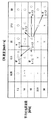
図5(a)および(b)は、基準条件に対し、マルチパス数、すなわち同一画像領域に対して記録走査する回数の変更とともに、記録ヘッドの平均吐出周波数とキャリッジの走査速度を変動させた場合の記録時間への影響を説明するための図である。ここで基準条件とは、図5(a)の左端部欄に示した条件、すなわち2パスのマルチパス記録を双方向で行い、キャリッジ速度が25インチ/秒の場合を示している。表中、一走査時間とは、同図(b)を参照するに、記録媒体の記録幅領域を1走査するために要する時間t1を示している。また、ランプU/D時間とは、所定の速度で等速移動しているキャリッジが減速し、停止し、反対方向の所定の速度まで加速するために要する時間t2を示している。この値は、上記キャリッジの速度t1に応じて変動する。更に、一走査総所要時間とは、2パス記録においては、キャリッジによる一往復の記録主走査のために要する時間を示しており、他のマルチパス数(P)においては2パスの一往復で完成される画像領域を完成させるのに要される時間を示している。例えば、4(P)パス記録であれば、2パスが2回の記録走査で完成される領域を4(P)回の記録走査で完成させることになるので、2パスの一走査層所要時間に対し4/2=2(P/2)を乗算した値となっている。
5A and 5B, the average ejection frequency of the recording head and the scanning speed of the carriage were changed with the change of the number of multi-passes, that is, the number of times of recording scanning for the same image area, with respect to the reference condition. It is a figure for demonstrating the influence on the recording time in a case. Here, the reference condition indicates the condition shown in the left end column of FIG. 5A, that is, the case where two-pass multi-pass printing is performed bidirectionally and the carriage speed is 25 inches / second. In the table, one scanning time indicates the time t1 required for one scanning of the recording width region of the recording medium, with reference to FIG. The ramp U / D time indicates a time t2 required for the carriage moving at a constant speed to decelerate, stop, and accelerate to a predetermined speed in the opposite direction. This value varies according to the carriage speed t1. Further, the total time required for one scan indicates the time required for one-way recording main scanning by the carriage in two-pass printing, and in two passes one round-trip for other multi-pass numbers (P). It shows the time required to complete the completed image area. For example, in the case of 4 (P) pass printing, an area where 2 passes are completed by 2 print scans is completed by 4 (P) print scans, so the time required for 1 scan layer of 2
図5(a)において、 条件Aは、キャリッジ速度は基準条件と等しいまま、マルチパス数を4パスに変更した場合を示している。走査回数が基準条件の倍に増えていることから一走査総所要時間も倍に増大している。条件Bは、マルチパス数は基準条件と等しいまま、キャリッジ速度を1/2に落とした状態を示している。キャリッジ速度が低速になった分、一走査総所要時間も基準条件に比べて増大している。条件B´は、マルチパス数を1パスに変更するとともに、記録ヘッドの吐出周波数を基準条件から変えないために、キャリッジ速度を1/2に低減した状態を示している。キャリッジ速度は低減されているが、マルチパス数を少なくした効果により、一走査総所要時間は基準条件に比べて低減している。条件Cは、マルチパス数を4パスに変更すると同時に、キャリッジ速度も倍速にした場合を示している。マルチパス数を増大させた分、一走査総所要時間は増えているが、キャリッジ速度も同時に上げているので、条件Aの場合よりは少なく抑えられている。また、条件C´は、マルチパス数を3パスに増やすと同時に、キャリッジ速度も3/2倍に上げた状態を示している。マルチパス数を増やした分一走査総所要時間は増大するが、キャリッジ速度も上げているので、基準条件の3/2倍までは増えていない。更に、条件Dは、マルチパス数はそのままで、キャリッジ速度を2倍に増やした場合を示している。キャリッジ速度を2倍にしている分、一走査時間は半分に低減しているが、キャリッジが高速になるほどランプU/D時間は増大するので、一走査総記録時間に関しては基準条件とあまり変わりはない。 In FIG. 5A, the condition A shows a case where the number of multi-passes is changed to 4 passes while the carriage speed is equal to the reference condition. Since the number of scans has doubled the reference condition, the total time required for one scan has also doubled. Condition B shows a state in which the carriage speed is reduced to ½ while the number of multipaths is equal to the reference condition. Since the carriage speed is reduced, the total time required for one scan is increased as compared with the reference condition. Condition B ′ shows a state in which the carriage speed is reduced to ½ in order to change the number of multi-passes to 1 and not change the ejection frequency of the recording head from the reference condition. Although the carriage speed is reduced, the total time required for one scan is reduced as compared with the reference condition due to the effect of reducing the number of multi-passes. Condition C shows a case where the number of multi-passes is changed to 4 and at the same time the carriage speed is doubled. Although the total time required for one scan increases as the number of multi-passes is increased, the carriage speed is also increased at the same time. Condition C ′ indicates a state in which the number of multi-passes is increased to 3 and at the same time the carriage speed is increased to 3/2 times. Although the total time required for one scan increases as the number of multi-passes is increased, the carriage speed is also increased, so it has not increased to 3/2 times the reference condition. Further, the condition D shows a case where the carriage speed is doubled while the number of multi-passes remains unchanged. Since the carriage speed is doubled, the one scanning time is reduced to half, but the ramp U / D time increases as the carriage speed increases, so the total recording time for one scanning is not much different from the reference condition. Absent.
図6は、上記のように基準条件に対して様々に条件を振って一様な画像を記録した場合の、端部よれ現象の程度を説明するための図である。図において、横軸はキャリッジの走査速度であり、25インチ/秒を中心とした5段階の速度を示している。また、縦軸は吐出口列当たりの平均吐出周波数であり、7.5KHz〜30KHzまでの5段階の周波数を示している。この平均吐出周波数は、上記一様な画像を記録する際のマルチパス数と、キャリッジ速度によって、定められる値である。それぞれの条件において示した印は、○が端部よれ現象の弊害が目立たない状態、△が然程目立たないが弊害が確認できる状態、×が弊害が目立つ状態を示している。 FIG. 6 is a diagram for explaining the degree of the end-to-end phenomenon when a uniform image is recorded under various conditions with respect to the reference condition as described above. In the drawing, the horizontal axis represents the scanning speed of the carriage, and shows five speeds centered on 25 inches / second. The vertical axis represents the average discharge frequency per discharge port array, and shows five stages of frequencies from 7.5 KHz to 30 KHz. This average ejection frequency is a value determined by the number of multi-passes when the uniform image is recorded and the carriage speed. The mark shown in each condition indicates a state in which the bad effect of the phenomenon due to the edge portion is not noticeable, a state in which Δ is not so noticeable but the harmful effect can be confirmed, and a state in which the bad effect is noticeable.
図5(a)で説明した基準条件は、表の中央に示しており、端部よれの評価は△である。また、基準条件に対して6種類の方法で条件を振った条件A〜Dは、表中にそれぞれの記号で示している。例えば条件Aの場合、一走査総記録時間は増大しているが、マルチパス数が増え、平均吐出周波数が半減している分、端部よれ現象は目立たなくなっている。条件Bの場合、マルチパス数は変えていないがキャリッジ速度を低下させた分、一走査総記録時間は増大しているが、平均吐出周波数が低減しているので端部よれ現象は目立ち難くなっている。但し、本発明者らの見解によれば、画像品位は十分ではない程度とみなしている。条件B´の場合、キャリッジスピードを低減しているが、マルチパス数も1パスに低減しているので平均吐出周波数の値は基準条件と変わらず、端部よれ現象も改善されていない。条件Cの場合、マルチパス数と同時にキャリッジ速度も増加させているので平均駆動周波数は基準条件と変わらないが、マルチパス数が2パスから4パスに増えている分、端部よれ弊害の影響が分散され、基準条件の場合よりは良好な画像が得られている。条件C´の場合、マルチパス数とキャリッジ速度の増加に伴い、平均駆動周波数は基準条件より低減している。よって、平均駆動周波数の低下とマルチパス数の増加の効果により、端部よれの程度は良好になっている。条件Dの場合、マルチパス数はそのままでキャリッジ速度を増大させているので、平均吐出周波数も増大し、端部よれ現象の程度は改善されていない。 The reference condition described with reference to FIG. 5A is shown in the center of the table, and the evaluation of the edge portion is Δ. In addition, conditions A to D in which conditions are given by six kinds of methods with respect to the reference conditions are indicated by respective symbols in the table. For example, in the case of condition A, although the total recording time for one scan is increased, the phenomenon of the edge portion becomes inconspicuous as the number of multi-passes increases and the average ejection frequency is halved. In condition B, although the number of multi-passes is not changed, the total recording time for one scan increases as the carriage speed is lowered, but the average ejection frequency is reduced, so the end-to-end phenomenon is less noticeable. ing. However, according to the view of the present inventors, the image quality is considered to be insufficient. In the case of condition B ′, the carriage speed is reduced, but since the number of multi-passes is also reduced to one pass, the value of the average ejection frequency is not different from the reference condition, and the edge sway phenomenon is not improved. In condition C, the carriage speed is increased at the same time as the number of multi-passes, so the average drive frequency does not change from the reference condition, but the influence of the adverse effects on the edges is increased by the amount of multi-passes increasing from 2 to 4 passes. Are dispersed, and an image better than that in the reference condition is obtained. In the case of the condition C ′, the average driving frequency is reduced from the reference condition as the number of multipaths and the carriage speed increase. Therefore, the degree of edge deflection is good due to the effect of lowering the average drive frequency and increasing the number of multipaths. In the condition D, the carriage speed is increased with the number of multi-passes as it is, so the average discharge frequency is also increased, and the degree of the end-to-end phenomenon is not improved.
本発明者らは、図5(a)や図6に示した評価結果より、端部よれ現象の品位が許容できる範囲(すなわち評価が○の条件)であって、なるべくスループットの向上を期待できる条件で画像を記録するような構成を設けることが有効であると判断した。但し、図6に示した平均吐出周波数は、マルチパス数やキャリッジ速度のほか、記録すべき画像の記録密度によっても変動する。よって、本実施例においては、既に説明したように、ページ内の記録密度を予め取得する手段を設け、得られた記録密度に応じて、端部よれの発生しないマルチパス数とキャリッジ速度の組み合わせが選択されるような構成を備えるものとする。 Based on the evaluation results shown in FIG. 5A and FIG. 6, the present inventors are within a range in which the quality of the end-to-end phenomenon can be tolerated (that is, the condition where the evaluation is ◯), and the improvement in throughput can be expected as much as possible. It was determined that it would be effective to provide a configuration for recording an image under conditions. However, the average ejection frequency shown in FIG. 6 varies depending on the recording density of the image to be recorded in addition to the number of multipasses and the carriage speed. Therefore, in this embodiment, as already described, a means for acquiring the recording density in the page in advance is provided, and the combination of the number of multi-passes and the carriage speed in which the edge portion does not occur according to the obtained recording density. Is selected.
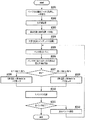
図7は、本実施例の記録装置におけるコントローラ200が行う記録制御工程を説明するためのフローチャートである。ホスト装置210から記録実行コマンドが入力されると、コントローラ200は、まずステップS101において、ページ全体の画像データを取得し、インク色毎にRAM205内に一時的に格納する。このとき格納される画像データは、各画素が0〜255で表される600ppiの濃度データである。数値が高いほど、濃度が高い、すなわち記録密度が高くなることを示している。その後、ステップS102に進み、ページ内における最大の平均濃度値Mdを取得する。
FIG. 7 is a flowchart for explaining a recording control process performed by the
図8(a)および(b)は、本実施例における平均濃度最大値Mdの算出方法を説明するための模式図である。図8(b)はステップS102で2値化された画像データ領域を模式的に示した図である。本実施例では、このような画像データ領域を、600ppiのd画素×w画素の単位領域に分割し、それぞれの単位領域内での平均濃度値を算出する。つまり、d画素×w画素領域に含まれる各画素の濃度値(0〜255)を調べ領域内の平均値を算出する。そして、ページ内に含まれる全単位領域の中で最も大きな値を平均濃度最大値Mdと定めることとする。図において、X0は画像データの主走査方向幅に含まれる単位領域の個数を示し、Y0は画像データの副走査方向幅に含まれる単位領域の個数を示している。 FIGS. 8A and 8B are schematic diagrams for explaining a method of calculating the average density maximum value Md in this embodiment. FIG. 8B is a diagram schematically showing the image data area binarized in step S102. In this embodiment, such an image data area is divided into 600 ppi d pixel × w pixel unit areas, and an average density value in each unit area is calculated. That is, the density value (0 to 255) of each pixel included in the d pixel × w pixel region is examined, and the average value in the region is calculated. Then, the largest value among all the unit areas included in the page is determined as the average density maximum value Md. In the figure, X0 indicates the number of unit areas included in the width of the image data in the main scanning direction, and Y0 indicates the number of unit areas included in the width of the image data in the sub-scanning direction.
図9は、ステップS102において、コントローラ200が行う平均濃度最大値Mdを取得するための工程を説明するためのフローチャートである。まず、コントローラ200は、変数yおよびMdを初期値0にセットする(ステップS201)。続くステップS202では、変数xを0にセットする。ここで、xは各単位領域の主走査方向の位置を管理するための変数、yは副走査方向の位置を管理するための変数である。
FIG. 9 is a flowchart for explaining the process for obtaining the average density maximum value Md performed by the
ステップS203では、注目する単位領域内の平均の記録濃度Avgを算出し、これをMdと比較する。すなわち、注目する単位領域内に含まれる全ての画素の濃度値を取得し、これらの平均値Avgと現段階の平均濃度最大値Mdとを比較する。Avg>Mdであった場合、注目する単位領域から得られた平均濃度値が現段階の平均濃度最大値Mdであると判断し、ステップS204へ進みMd=Avgとする。一方、Avg≦Mdであった場合、平均濃度最大値Mdは現状のままで良いと判断し、ステップ205へ進む。 In step S203, the average recording density Avg in the unit area of interest is calculated and compared with Md. That is, the density values of all the pixels included in the unit area of interest are acquired, and the average value Avg is compared with the average density maximum value Md at the current stage. If Avg> Md, it is determined that the average density value obtained from the unit area of interest is the average density maximum value Md at the current stage, and the process proceeds to step S204 where Md = Avg. On the other hand, if Avg ≦ Md, it is determined that the average density maximum value Md may remain as it is, and the process proceeds to step 205.
ステップS205では、注目する単位領域を主走査方向に1つ分ずらすために、xをインクリメントし、ステップS206へ進む。ステップS206では、パラメータxとX0を比較し、x=X0である場合には、主走査方向に配列する一連の単位領域は全て検出積みであると判断しステップS207へ進む。一方、x≠X0である場合には、主走査方向に隣接する次の単位領域の平均濃度を検出するためにステップS203へ戻る。 In step S205, x is incremented to shift the unit area of interest by one in the main scanning direction, and the process proceeds to step S206. In step S206, the parameters x and X0 are compared. If x = X0, it is determined that all the series of unit areas arranged in the main scanning direction are detection stacks, and the process proceeds to step S207. On the other hand, if x ≠ X0, the process returns to step S203 to detect the average density of the next unit area adjacent in the main scanning direction.
ステップS207では、注目する単位領域を副走査方向に1つ分ずらすために、yをインクリメントし、ステップS208へ進む。ステップS208では、パラメータyとY0を比較し、y=Y0である場合には、主走査方向に配列する一連の単位領域は全て検出積みであると判断し、図7のステップ103に戻る。一方、y≠Y0である場合には、副走査方向に隣接する次の単位領域の平均濃度を検出するためにステップS202に戻る。このような工程によって最終的に得られたMdは、ページ内の全単位領域において、最大の平均濃度を示す値となる。すなわち、ここで得られた平均濃度最大値を有する単位領域が、ページ内で最も濃度の高い領域、記録密度の高い領域、そして端部よれ現象が懸念される領域となる。従って、当該領域における端部よれ現象が回避されるような記録方法が選択されれば、ページ内の全ての領域においても端部よれ現象は回避できる。 In step S207, y is incremented in order to shift the unit area of interest by one in the sub-scanning direction, and the process proceeds to step S208. In step S208, the parameters y and Y0 are compared. If y = Y0, it is determined that all the series of unit areas arranged in the main scanning direction are detection stacks, and the process returns to step 103 in FIG. On the other hand, if y ≠ Y0, the process returns to step S202 to detect the average density of the next unit area adjacent in the sub-scanning direction. The Md finally obtained by such a process is a value indicating the maximum average density in all unit regions in the page. That is, the unit area having the maximum average density obtained here is the area with the highest density in the page, the area with the high recording density, and the area where the edge twist phenomenon is a concern. Therefore, if a recording method that avoids the edge twisting phenomenon in the area is selected, the edge twisting phenomenon can be avoided in all the areas in the page.
図7のフローチャートに戻る。ステップS102によって平均濃度最大値Mdが得られるとステップS103へ進み、次にコントローラ200は、Mdの値が0〜85、86〜170および171〜255のいずれに含まれるかによって工程を分岐する。そして、0≦Md≦85の場合はステップS104へ、86≦Md≦170の場合はステップS105へ、更に171≦Md≦255の場合はステップS106へそれぞれ進む。
Returning to the flowchart of FIG. When the average density maximum value Md is obtained in step S102, the process proceeds to step S103. Next, the
ステップS104〜S106では、コントローラ200が、予めROM203内に格納されているテーブルを参照することにより、それぞれのMdに対応したキャリッジ速度およびマルチパス数を設定する。
In steps S104 to S106, the
図10は、ROM203に格納されているテーブルの内容を説明するための図である。Mdが0≦Md≦85の場合は、キャリッジ速度25インチ/秒の2パス記録が設定される。86≦Md≦170の場合は、キャリッジ速度37.5インチ/秒の3パス記録が設定される。更に、171≦Md≦255の場合は、キャリッジ速度50インチ/秒の4パス記録が設定される。結果、比較的Mdの値が低い、すなわちドットの記録密度が低いときのみ図5(a)で示した基準条件が設定され、記録密度が高まるにつれて、条件C´、条件Cと段階的にマルチパス数を多く且つキャリッジ速度が速い条件が設定される。
FIG. 10 is a diagram for explaining the contents of the table stored in the
ステップS104〜S106によってキャリッジ速度とマルチパス数が設定されると、ステップS107に進み、コントローラ200は、600ppiで格納されている全色全画素に対し2値化処理を行い、1200dpiの2値データに変換する。このとき採用する2値化方法は、誤差拡散方法やディザ法など公知の技術を採用することが出来る。更に、ステップS108に進み、コントローラ200は、2値化後の画像データをヘッドドライバに転送しつつ、設定されたマルチパス数とキャリッジ速度に従って各種ドライバを制御することにより、記録媒体に1ページ分の画像を記録する。以上で本処理が終了する。
When the carriage speed and the number of multi-passes are set in steps S104 to S106, the process proceeds to step S107, and the
以上説明したように、本実施例によれば、記録すべき画像のページ内の濃度の最大値を記録密度情報として検知し、この値に応じてマルチパス数とキャリッジ速度を設定する。これにより、然程画像濃度が高くないページにおいても必要以上にスループットを低減することなく、ページごとに最適な記録方法で端部よれが発生しない好適な画像を出力することが可能となる。 As described above, according to the present embodiment, the maximum density value in the page of the image to be recorded is detected as the recording density information, and the number of multi-passes and the carriage speed are set according to this value. As a result, it is possible to output a suitable image in which the edge portion does not occur with an optimum recording method for each page without reducing the throughput more than necessary even on a page where the image density is not so high.
なお、本実施例において単位領域d×wの、副走査方向の幅wは記録ヘッドの記録幅に相当する値が適切であるが、主走査方向の幅dは端部よれ現象の発生状態に応じて可変である。再度図1を参照するに、一般的な端部よれ現象は、記録ヘッドが主走査方向に走査する際、記録開始位置から顕著に現れるわけではない。記録走査が開始され、ある程度の吐出動作が連続的に行われ更に気流が発生した結果、発生する現象である。よって実際の端部よれ現象が確認されるのは、記録走査開始位置からある程度距離を置いた位置からとなる。本実施例ではこの距離に相当する画素数を実験的に求めた結果、約5mmであったため、600dpiのこの幅に相当する128画素を単位領域の幅dとしている。これにより、少なくとも個々の単位領域に対する走査内において端部よれ現象が発生することは回避できる。 In the present embodiment, the width w in the sub-scanning direction of the unit area d × w is appropriately a value corresponding to the recording width of the recording head, but the width d in the main scanning direction is in a state where an end-to-edge phenomenon occurs. It is variable accordingly. Referring to FIG. 1 again, the general edge twist phenomenon does not appear remarkably from the recording start position when the recording head scans in the main scanning direction. This is a phenomenon that occurs as a result of the start of recording scan, continuous discharge operation to a certain extent, and the generation of airflow. Therefore, the actual edge sway phenomenon is confirmed from a position at a certain distance from the recording scan start position. In the present embodiment, the number of pixels corresponding to this distance was experimentally obtained and found to be about 5 mm, so 128 pixels corresponding to this width of 600 dpi is set as the width d of the unit region. As a result, it is possible to avoid the occurrence of the edge sway phenomenon at least in the scanning for each unit region.
(実施例2)
以下に本発明の第2の実施例について説明する。本実施例においても図2〜図4で説明した記録装置および記録ヘッドを適用する。但し、第1の実施例と異なり、本実施例の記録装置には、ホスト装置210から、レッド(R)、グリーン(G)およびブルー(B)の多値の輝度データが600ppiで入力されるものとする。そして、コントローラ200によって様々な画像処理を施した後、2値の濃度データが表すドットの記録密度から、マルチパス数やキャリッジ速度を設定するものとする。
(Example 2)
The second embodiment of the present invention will be described below. Also in this embodiment, the recording apparatus and the recording head described with reference to FIGS. However, unlike the first embodiment, multi-value luminance data of red (R), green (G), and blue (B) is input at 600 ppi from the
図11は、本実施例の記録装置におけるコントローラ200が行う記録制御工程を説明するためのフローチャートである。ホスト装置210から記録実行コマンドが入力されると、コントローラ200は、まずステップS301において、ページ全体の画像データを取得し、RAM205内に一時的に格納する。このとき格納される画像データは、各画素が0〜255で表される600ppiの輝度データ(RGB)である。
FIG. 11 is a flowchart for explaining a recording control process performed by the
続くステップS302でコントローラ200は、格納された輝度データ(RGB)を色分解し、記録装置が用いる6色インク用の濃度データに変換する。この色分解処理により、各画素が0〜255で表される600ppiの濃度データが6色分(Bk、LC、C、LM、M、Y)生成され、保存される。
In subsequent step S302, the
更に、ステップS303に進み、600ppiの256階調の濃度データは、多値の誤差拡散処理により、同じく600ppiの5値(0〜4)の濃度データに変換される。更に、ステップS304において、600dpiの5値の濃度データは、1200dpiの2値の濃度データに変換される。本実施例において、このときの2値化方法はインデックス展開処理を採用する。 In step S303, density data of 256 gradations of 600 ppi is converted into density data of 5 values (0 to 4) of 600 ppi by multi-value error diffusion processing. Further, in step S304, the 600 dpi 5-value density data is converted into 1200 dpi 2-value density data. In this embodiment, the binarization method at this time employs index expansion processing.
インデックス展開処理では、600dpiの各画素に与えられる濃度値を、それぞれの濃度値に対応したドットパターンに変換する。600dpiの1画素領域は、1200dpiでは2画素×2画素領域に相当し、1200dpiの各画素はドットを記録する画素(1)とドットを記録しない画素(0)に分類される。濃度値が上昇するに連れて、ドットを記録する画素が徐々に増えていくように設定されている。本実施例において、コントローラ200内のROM203には、このように濃度値に対応付けられたパターンが予め記憶されている。そして、CPU201はこのパターンを参照することにより、600dpiの5値データを、1200dpiの2値データに変換することが出来る。
In the index development process, the density value given to each pixel of 600 dpi is converted into a dot pattern corresponding to each density value. One pixel area of 600 dpi corresponds to a 2 pixel × 2 pixel area at 1200 dpi, and each pixel of 1200 dpi is classified into a pixel (1) for recording dots and a pixel (0) for not recording dots. It is set so that the number of pixels for recording dots gradually increases as the density value increases. In this embodiment, the
再び図11に戻る。ステップS305では、2値化された1ページ分の2値データのうち、次の記録走査で記録する領域に対し2パス用のマスクパターンをかけ、パス分割する。具体的には、1走査分の2値の画像データと、ドット記録の許容・非許容が定められた2パス用のマスクパターンとの間で論理積をとり、約半分に間引かれた1走査分のドットデータを得る。 Returning again to FIG. In step S305, a 2-pass mask pattern is applied to an area to be recorded in the next recording scan in the binarized binary data for one page, and the pass is divided. Specifically, a logical product is obtained between binary image data for one scan and a two-pass mask pattern for which dot recording is permitted / non-permitted. Obtain dot data for scanning.
更に、ステップS306では、ステップS305で得られた1走査分のドットデータ領域を図12に示すように単位領域(d×w)ごとに検出し、1走査内におけるドット記録密度の最大値Mdを取得する。 Further, in step S306, the dot data area for one scan obtained in step S305 is detected for each unit area (d × w) as shown in FIG. 12, and the maximum value Md of dot recording density in one scan is determined. get.
本実施例におけるドット記録密度最大値Mdを取得するための工程も、第1の実施例と同様に図9に示したフローチャートに沿って略説明することが出来る。但し、本実施例では単位領域(d×w)内に記録されるドット数の割合を単位領域内のドット記録密度とし、ステップS203においては、この値を現段階の記録密度最大値Mdと比較する。また、本実施例では、記録走査毎にマルチパス数やキャリッジ速度を可変とするので、副走査方向用の変数yは用いないことから、ステップS207およびS208は省略される。 The process for obtaining the dot recording density maximum value Md in the present embodiment can also be roughly described along the flowchart shown in FIG. 9 as in the first embodiment. However, in this embodiment, the ratio of the number of dots recorded in the unit area (d × w) is the dot recording density in the unit area, and in step S203, this value is compared with the maximum recording density Md at the current stage. To do. Further, in this embodiment, since the number of multi-passes and the carriage speed are variable for each print scan, the variable y for the sub-scanning direction is not used, so steps S207 and S208 are omitted.
ステップS306によってページ内の記録密度最大値Mdが算出されると、ステップS307に進み、コントローラ200は、記録密度最大値Mdが0%≦Md≦25%の範囲に含まれるか、あるいは25%<Md≦50%の範囲に含まれるかを判断する。既にステップS305において、2パスでのパス分割が成された後のドットデータであるので、記録密度最大値Mdは最大でも50%となる。そして、0≦Md≦25の場合はステップS308へ、25<Md≦50の場合はステップS309へそれぞれ進む。
When the recording density maximum value Md in the page is calculated in step S306, the process proceeds to step S307, and the
ステップS308およびS309では、コントローラ200が、予めROM203内に格納されているテーブルを参照することにより、それぞれのMdに対応したキャリッジ速度およびマルチパス数を設定する。
In steps S308 and S309, the
図13は、ROM203に格納されているテーブルの内容を説明するための図である。Mdが0≦Md≦25の場合は、キャリッジ速度25インチ/秒の2パス記録が設定される。一方、25<Md≦50の場合は、キャリッジ速度50インチ/秒の4パス記録が設定される。
FIG. 13 is a diagram for explaining the contents of the table stored in the
ステップS308またはS309によってキャリッジ速度とマルチパス数が設定されるとステップS310に進み、コントローラ200は設定されたマルチパス数とキャリッジ速度に従って各種ドライバを制御することにより、記録媒体に1バンド分の記録を行う。
When the carriage speed and the number of multi-passes are set in step S308 or S309, the process proceeds to step S310, and the
具体的には、ステップS308によって2パスのマルチパス記録が設定されているとき、ステップS305のパス分割で得られた2値データを、そのままキャリッジ速度25インチ/秒で記録する。一方、ステップS309によって4パスのマルチパス記録が設定されているとき、ステップS305のパス分割で得られた2値データは更に2つに分割される。 Specifically, when 2-pass multi-pass printing is set in step S308, the binary data obtained by the pass division in step S305 is recorded as it is at a carriage speed of 25 inches / second. On the other hand, when 4-pass multi-pass printing is set in step S309, the binary data obtained by the pass division in step S305 is further divided into two.
図14(a)〜(c)は、4パスのマルチパス記録を行うために、2パス用にパス分割された画像データを更に2分割する方法を説明するための図である。図14(a)は、ステップS305において、2パスに分割された画像データを部分的に示した模式図である。図において、○を示した領域がドットを記録する1200dpiの画素を示している。図14(b)および(c)は、同図(a)を更に2分割した状態を示している。ここでは、主走査方向に対し、記録画素が1画素おきに配置するように、2つの画像データに分割されている。 FIGS. 14A to 14C are diagrams for explaining a method of further dividing the image data divided for two passes into two to perform four-pass multi-pass printing. FIG. 14A is a schematic diagram partially showing image data divided into two passes in step S305. In the figure, a region indicated by ◯ indicates a 1200 dpi pixel on which a dot is recorded. FIGS. 14B and 14C show a state where FIG. 14A is further divided into two parts. Here, the image data is divided into two image data so that the recording pixels are arranged every other pixel in the main scanning direction.
ステップS309によって4パスのマルチパス記録が設定された場合、本実施例ではこのように分割した2つのデータ図14(b)および(c)を2回の記録走査に分けて記録する。25インチ/秒のキャリッジ速度に相当する駆動周波数しか実現できない記録ヘッドであっても、図14に示すようにデータを2分割すれば、記録ヘッドの実質的な駆動周波数を変えることなく、キャリッジ速度を倍速にすることが出来る。本実施例の4パス記録モードでは、図14に示すような特徴的な分割方法を採用することにより、50インチ/秒のキャリッジ速度を実現しているのである。 When 4-pass multi-pass printing is set in step S309, in this embodiment, the two data FIGS. 14B and 14C divided in this way are divided into two printing scans. Even in a recording head that can realize only a driving frequency corresponding to a carriage speed of 25 inches / second, if the data is divided into two as shown in FIG. 14, the carriage speed is not changed without changing the substantial driving frequency of the recording head. Can be doubled. In the 4-pass printing mode of this embodiment, a carriage speed of 50 inches / second is realized by adopting a characteristic dividing method as shown in FIG.
設定されたマルチパス数およびキャリッジ速度によって1バンド分の記録が完了すると、記録媒体は副走査方向に所定量搬送され、ステップS311へ進む。ステップS311では、ページ内の全バンドに対する記録処理が完了したか否かを判断する。まだ記録すべきバンドが残っていると判断された場合は、ステップS305に戻り、次のバンド領域に対するパス分割を実行する。一方、ステップS311で、全てのバンドに対する記録処理が完了したと判断された場合には、本処理を終了する。 When the recording for one band is completed with the set number of multi-passes and the carriage speed, the recording medium is conveyed by a predetermined amount in the sub-scanning direction, and the process proceeds to step S311. In step S311, it is determined whether the recording process for all the bands in the page has been completed. If it is determined that there are still bands to be recorded, the process returns to step S305 to execute pass division for the next band area. On the other hand, if it is determined in step S311 that the recording process for all the bands has been completed, this process ends.
本実施例によれば、2パスのマルチパスを基本モードとしておきながらも、記録密度が高い走査領域が存在する記録走査のみ、キャリッジ速度を高速にした4パスのマルチパス記録に切り替えられる。よって、ページ内の最大濃度によってマルチパス数を決定してしまう第1の実施例に比べて、更に効率的にスループット上げながら、端部よれが発生しない画像を出力することが可能となる。また、ドット記録密度最大値Mdを検出するためにコントローラ200に必要とされるメモリサイズも、ページ内の全領域を検索する第1の実施例に比べて小さくて済むので、より安価な装置を実現することが可能となる。
According to the present embodiment, while the two-pass multi-pass is set as the basic mode, only the recording scan in which the scanning area having a high recording density exists can be switched to the four-pass multi-pass printing with a high carriage speed. Therefore, compared to the first embodiment in which the number of multi-passes is determined by the maximum density in the page, it is possible to output an image that does not cause edge distortion while increasing the throughput more efficiently. Further, since the memory size required for the
4 キャリッジモータ
25 電気熱変換体(ヒータ)
34 搬送モータ
200 コントローラ
203 ROM
205 RAM
210 ホスト装置
212 インターフェイス
240 ヘッドドライバ
250 キャリッジモータドライバ
270 搬送モータドライバ
H1000 記録ヘッド
4
34
205 RAM
210
Claims (6)
前記画像データより、ドットの記録密度情報を検知する手段と、
該記録密度情報に応じて、前記記録主走査の走査速度および前記記録媒体の同一画像領域に対する前記記録主走査の走査回数を設定する手段と、
設定された前記走査速度および前記走査回数に従って前記記録媒体に画像を記録する手段と、を備え、
前記設定手段は、前記記録密度情報の値が大きいほど前記走査回数を多く且つ前記走査速度を大きく設定することを特徴とするインクジェット記録装置。 A recording main scan in which a recording head configured by arranging a plurality of recording elements for recording dots on the recording medium based on image data is moved relative to the recording medium, and the recording medium in a direction crossing the recording main scan In an inkjet recording apparatus that forms an image on the recording medium by intermittently repeating sub-scanning that conveys
Means for detecting dot recording density information from the image data;
Means for setting the scanning speed of the recording main scan and the number of scans of the recording main scan for the same image area of the recording medium in accordance with the recording density information;
Means for recording an image on the recording medium according to the set scanning speed and the number of scans,
The ink jet recording apparatus, wherein the setting means sets the number of scanning times and the scanning speed to be larger as the value of the recording density information is larger.
前記画像データより、ドットの記録密度情報を検知する工程と、
該記録密度情報に応じて、前記記録主走査の走査速度および前記記録媒体の同一画像領域に対する前記記録主走査の走査回数を設定する工程と、
設定された前記走査速度および前記走査回数に従って前記記録媒体に画像を記録する工程と、を有し、
前記設定工程は、前記記録密度情報の値が大きいほど前記走査回数を多く且つ前記走査速度を大きく設定することを特徴とするインクジェット記録方法。 A recording main scan in which a recording head configured by arranging a plurality of recording elements for recording dots on the recording medium based on image data is moved relative to the recording medium, and the recording medium in a direction crossing the recording main scan In the ink jet recording method for forming an image on the recording medium by intermittently repeating sub-scanning to convey
A step of detecting dot recording density information from the image data;
Setting the scanning speed of the recording main scan and the number of scans of the recording main scan for the same image area of the recording medium according to the recording density information;
Recording an image on the recording medium according to the set scanning speed and the number of scans, and
In the inkjet recording method, the setting step sets the number of scanning times and the scanning speed to be larger as the value of the recording density information is larger.
Priority Applications (2)
| Application Number | Priority Date | Filing Date | Title |
|---|---|---|---|
| JP2006334730A JP2008143091A (en) | 2006-12-12 | 2006-12-12 | Inkjet recorder and inkjet recording method |
| US11/953,996 US7695088B2 (en) | 2006-12-12 | 2007-12-11 | Ink jet printing apparatus and ink jet printing method |
Applications Claiming Priority (1)
| Application Number | Priority Date | Filing Date | Title |
|---|---|---|---|
| JP2006334730A JP2008143091A (en) | 2006-12-12 | 2006-12-12 | Inkjet recorder and inkjet recording method |
Publications (2)
| Publication Number | Publication Date |
|---|---|
| JP2008143091A true JP2008143091A (en) | 2008-06-26 |
| JP2008143091A5 JP2008143091A5 (en) | 2010-05-20 |
Family
ID=39542147
Family Applications (1)
| Application Number | Title | Priority Date | Filing Date |
|---|---|---|---|
| JP2006334730A Pending JP2008143091A (en) | 2006-12-12 | 2006-12-12 | Inkjet recorder and inkjet recording method |
Country Status (2)
| Country | Link |
|---|---|
| US (1) | US7695088B2 (en) |
| JP (1) | JP2008143091A (en) |
Families Citing this family (5)
| Publication number | Priority date | Publication date | Assignee | Title |
|---|---|---|---|---|
| JP5139876B2 (en) * | 2008-04-25 | 2013-02-06 | キヤノン株式会社 | Image forming apparatus and image forming method |
| JP2011005703A (en) * | 2009-06-24 | 2011-01-13 | Canon Inc | Ink jet recording apparatus and ink jet recording method |
| US8711425B2 (en) * | 2010-05-28 | 2014-04-29 | Hewlett-Packard Development Company, L.P. | Selecting one of a plurality of print modes based on pixel coverage of a document |
| US9757955B2 (en) * | 2015-12-09 | 2017-09-12 | Funai Electric Co., Ltd. | Imaging apparatus and method of using colorant density for reducing printing defects |
| US10137690B2 (en) | 2016-01-29 | 2018-11-27 | Canon Kabushiki Kaisha | Ink jet recording apparatus and ink jet recording method |
Citations (9)
| Publication number | Priority date | Publication date | Assignee | Title |
|---|---|---|---|---|
| JPH05309874A (en) * | 1992-02-26 | 1993-11-22 | Canon Inc | Recording method and device of image, record, and processed product |
| JPH05318768A (en) * | 1992-05-25 | 1993-12-03 | Canon Inc | Recording apparatus |
| JPH06106734A (en) * | 1992-09-29 | 1994-04-19 | Toppan Printing Co Ltd | Method and device for printing |
| JPH0789161A (en) * | 1993-04-28 | 1995-04-04 | Canon Inc | Device and method for forming image |
| JPH09240025A (en) * | 1996-03-12 | 1997-09-16 | Canon Inc | Recording apparatus and its method |
| JP2001180045A (en) * | 1999-12-27 | 2001-07-03 | Canon Inc | Image recording device |
| US6390585B1 (en) * | 1998-07-21 | 2002-05-21 | Hewlett-Packard Company | Selectively warming a printhead for optimized performance |
| JP2005224955A (en) * | 2004-02-10 | 2005-08-25 | Canon Inc | Printer |
| JP2006007759A (en) * | 2004-05-26 | 2006-01-12 | Canon Inc | Recording apparatus, controlling method and computer program |
Family Cites Families (8)
| Publication number | Priority date | Publication date | Assignee | Title |
|---|---|---|---|---|
| JPS5451837A (en) | 1977-09-30 | 1979-04-24 | Ricoh Co Ltd | Ink jet head device |
| JP2960608B2 (en) | 1992-06-04 | 1999-10-12 | キヤノン株式会社 | Method for manufacturing liquid jet recording head |
| TW226450B (en) | 1992-08-31 | 1994-07-11 | Canon Kk | |
| US5790150A (en) * | 1994-02-17 | 1998-08-04 | Colorspan Corporation | Method for controlling an ink jet printer in a multipass printing mode |
| US6270178B1 (en) * | 1995-05-30 | 2001-08-07 | Canon Kabushiki Kaisha | Method and apparatus for measuring the amount of discharged ink, printing apparatus, and method of measuring the amount of ink discharged in the printing apparatus |
| JP4164224B2 (en) | 1999-08-24 | 2008-10-15 | キヤノン株式会社 | Inkjet recording apparatus and inkjet recording method |
| EP1080919B1 (en) | 1999-08-24 | 2007-08-15 | Canon Kabushiki Kaisha | Ink jet printing apparatus and ink jet printing method |
| JP4666810B2 (en) | 2001-05-24 | 2011-04-06 | キヤノン株式会社 | Image recording apparatus and control method thereof |
-
2006
- 2006-12-12 JP JP2006334730A patent/JP2008143091A/en active Pending
-
2007
- 2007-12-11 US US11/953,996 patent/US7695088B2/en not_active Expired - Fee Related
Patent Citations (9)
| Publication number | Priority date | Publication date | Assignee | Title |
|---|---|---|---|---|
| JPH05309874A (en) * | 1992-02-26 | 1993-11-22 | Canon Inc | Recording method and device of image, record, and processed product |
| JPH05318768A (en) * | 1992-05-25 | 1993-12-03 | Canon Inc | Recording apparatus |
| JPH06106734A (en) * | 1992-09-29 | 1994-04-19 | Toppan Printing Co Ltd | Method and device for printing |
| JPH0789161A (en) * | 1993-04-28 | 1995-04-04 | Canon Inc | Device and method for forming image |
| JPH09240025A (en) * | 1996-03-12 | 1997-09-16 | Canon Inc | Recording apparatus and its method |
| US6390585B1 (en) * | 1998-07-21 | 2002-05-21 | Hewlett-Packard Company | Selectively warming a printhead for optimized performance |
| JP2001180045A (en) * | 1999-12-27 | 2001-07-03 | Canon Inc | Image recording device |
| JP2005224955A (en) * | 2004-02-10 | 2005-08-25 | Canon Inc | Printer |
| JP2006007759A (en) * | 2004-05-26 | 2006-01-12 | Canon Inc | Recording apparatus, controlling method and computer program |
Also Published As
| Publication number | Publication date |
|---|---|
| US7695088B2 (en) | 2010-04-13 |
| US20080150991A1 (en) | 2008-06-26 |
Similar Documents
| Publication | Publication Date | Title |
|---|---|---|
| JP5013712B2 (en) | Inkjet recording apparatus and inkjet recording method | |
| JP4717620B2 (en) | Inkjet recording method and inkjet recording apparatus | |
| JP5038076B2 (en) | Inkjet recording apparatus and inkjet recording method | |
| US20100013878A1 (en) | Bi-directional print masking | |
| JP2006341406A (en) | Inkjet recording system | |
| JP2007296754A (en) | Ink-jet recording method and mist-reduction-condition setting device | |
| WO2006064820A1 (en) | Ink jet recording method and ink jet recording device | |
| JP2011143712A (en) | Ink-jet recording device and ink-jet recording method | |
| JP2008168629A (en) | Inkjet recorder and inkjet recording method | |
| JP5478875B2 (en) | Inkjet recording apparatus and inkjet recording method | |
| WO2014125679A1 (en) | Recording device and recording method | |
| JP4006198B2 (en) | Inkjet recording method, recording apparatus, and data processing method | |
| JP4480175B2 (en) | Inkjet recording method and inkjet recording apparatus | |
| JP5698505B2 (en) | Inkjet recording device | |
| JP2008143091A (en) | Inkjet recorder and inkjet recording method | |
| JP2006168073A (en) | Inkjet recording system | |
| JPH0811298A (en) | Ink jet recording method and apparatus | |
| JP5224684B2 (en) | Inkjet recording apparatus and inkjet recording method | |
| JP2007168202A (en) | Ink-jet recording device, data processor, and ink-jet recording method | |
| JP5979812B2 (en) | Image processing apparatus and image processing method | |
| JP4468016B2 (en) | Inkjet recording apparatus and inkjet recording method | |
| JP2009061774A (en) | Inkjet recorder and inkjet recording method | |
| JP5273919B2 (en) | Inkjet recording method and inkjet recording apparatus | |
| JP4280400B2 (en) | Inkjet recording method, recording apparatus, and data processing method | |
| JP2005349605A (en) | Ink jet recording method and ink jet recorder |
Legal Events
| Date | Code | Title | Description |
|---|---|---|---|
| A621 | Written request for application examination |
Free format text: JAPANESE INTERMEDIATE CODE: A621 Effective date: 20091214 |
|
| A521 | Request for written amendment filed |
Free format text: JAPANESE INTERMEDIATE CODE: A523 Effective date: 20100402 |
|
| RD02 | Notification of acceptance of power of attorney |
Free format text: JAPANESE INTERMEDIATE CODE: A7422 Effective date: 20101106 |
|
| A977 | Report on retrieval |
Free format text: JAPANESE INTERMEDIATE CODE: A971007 Effective date: 20110929 |
|
| A131 | Notification of reasons for refusal |
Free format text: JAPANESE INTERMEDIATE CODE: A131 Effective date: 20111007 |
|
| A131 | Notification of reasons for refusal |
Free format text: JAPANESE INTERMEDIATE CODE: A131 Effective date: 20130305 |
|
| A521 | Request for written amendment filed |
Free format text: JAPANESE INTERMEDIATE CODE: A523 Effective date: 20130507 |
|
| A02 | Decision of refusal |
Free format text: JAPANESE INTERMEDIATE CODE: A02 Effective date: 20130528 |