JP4717620B2 - Inkjet recording method and inkjet recording apparatus - Google Patents
Inkjet recording method and inkjet recording apparatus Download PDFInfo
- Publication number
- JP4717620B2 JP4717620B2 JP2005359510A JP2005359510A JP4717620B2 JP 4717620 B2 JP4717620 B2 JP 4717620B2 JP 2005359510 A JP2005359510 A JP 2005359510A JP 2005359510 A JP2005359510 A JP 2005359510A JP 4717620 B2 JP4717620 B2 JP 4717620B2
- Authority
- JP
- Japan
- Prior art keywords
- recording
- image data
- area
- scanning
- nozzle
- Prior art date
- Legal status (The legal status is an assumption and is not a legal conclusion. Google has not performed a legal analysis and makes no representation as to the accuracy of the status listed.)
- Expired - Fee Related
Links
Images


Description
本発明は、インクを吐出するノズルを高密度に配列してなるノズル列を有するインクジェット記録ヘッドを用いて、記録媒体上に画像を記録するインクジェット記録方法およびインクジェット記録装置に関する。 The present invention relates to an ink jet recording method and an ink jet recording apparatus for recording an image on a recording medium using an ink jet recording head having a nozzle row in which nozzles for ejecting ink are arranged at high density.
コンピュータやワードプロセッサ等の情報処理機器および通信機器の普及に伴い、それらの機器において処理されたデジタル画像情報を出力する出力装置の需要が高まっている。この出力装置の一つとして、インク滴を吐出して記録媒体上にドットを形成することにより画像を形成するインクジェット記録装置が急速に普及している。このインクジェット記録装置は、記録速度および記録画像の解像度の向上を図るため、インク滴を吐出するインク吐出口、液路、および記録素子等からなる吐出部(以下、ノズルともいう)を多数個、集積・配列した記録ヘッドを用いる。 With the spread of information processing devices such as computers and word processors and communication devices, there is an increasing demand for output devices that output digital image information processed by these devices. As one of the output devices, an ink jet recording apparatus that forms an image by ejecting ink droplets to form dots on a recording medium is rapidly spreading. In order to improve the recording speed and the resolution of a recorded image, this ink jet recording apparatus has a large number of ejection portions (hereinafter also referred to as nozzles) composed of ink ejection ports for ejecting ink droplets, liquid paths, and recording elements, An integrated and arranged recording head is used.
また、近年ではカラーの記録画像を出力可能とする要求が高まっている。このため、カラー画像を記録するインクジェット記録装置では、黒インクを吐出する記録ヘッドに加え、複数種のカラーインクを吐出するための記録ヘッドを用いて記録動作を行う。この際、記録ヘッドと記録媒体とは非接触な状態に保たれるため、低騒音での記録動作が可能となる。また、インクジェット記録装置は、ノズルの高密度化によって高解像度の画像を高速に記録することが可能である。しかも普通紙等の記録材に対しても現像や定着などの格別な処理を施す必要がないため、低価格で高品位な画像を得ることができるという種々の利点を有している。特に、オンデマンド型のインクジェット記録装置はそのカラー化が容易であり、かつ装置自体の小型化、簡略化が可能なことから将来の需要についても有望視されている。また、記録画像のカラー化の要求が高まるにつれ、インクジェット記録装置に対し、さらなる高画質化と高速化が要請されている。 In recent years, there has been an increasing demand to be able to output color recording images. For this reason, in an inkjet recording apparatus that records a color image, a recording operation is performed using a recording head that ejects a plurality of types of color inks in addition to a recording head that ejects black ink. At this time, since the recording head and the recording medium are kept in a non-contact state, the recording operation can be performed with low noise. Further, the ink jet recording apparatus can record high-resolution images at high speed by increasing the nozzle density. In addition, since there is no need to perform special processing such as development and fixing on a recording material such as plain paper, it has various advantages that a high-quality image can be obtained at a low price. In particular, an on-demand type ink jet recording apparatus is easy to color, and since the apparatus itself can be reduced in size and simplified, future demand is also promising. Further, as the demand for colorization of recorded images increases, there is a demand for higher image quality and higher speed for inkjet recording apparatuses.
一方、近年のノズルの集積配列化の技術進歩を背景に、さらに高密度かつ長尺な記録ヘッドの製作が可能になりつつある。一般に、高密度かつ長尺に製作された記録ヘッドは、長尺記録ヘッドと呼ばれており、この長尺記録ヘッドは、記録媒体に対する一回の記録走査によって記録媒体上に記録できる領域の幅を、従来の短尺な記録ヘッドを用いた場合に比べて拡大することが可能となる。このため、従来と同様に高い画像品質を維持しつつ、今までにない高速記録を実現できる極めて有用な技術として、さらなる技術開発が進められている。 On the other hand, against the background of recent technological advances in nozzle integration, it is becoming possible to manufacture recording heads with higher density and longer length. In general, a recording head manufactured in high density and long is called a long recording head, and this long recording head has a width of an area that can be recorded on the recording medium by a single recording scan on the recording medium. Can be enlarged as compared with the case where a conventional short recording head is used. For this reason, further technical development has been promoted as an extremely useful technique capable of realizing unprecedented high-speed recording while maintaining high image quality as in the past.
しかしながら、上記のような高密度かつ長尺な記録ヘッドを用いて記録動作を行うインクジェット記録装置にあっては、以下のような問題が発生することがある。
すなわち、ノズルを高密度に配列した長尺な記録ヘッドから同時に多数のインク滴を吐出すると共に、高速に記録ヘッドの記録走査ないしは記録媒体の走査を行うと、記録ヘッドと記録媒体との間に不規則な気流(乱流)が発生する。その結果、インク滴の着弾位置が乱れるという問題が生じる。また、記録ヘッドと記録媒体との間に生じる乱流は、インク液滴の吐出状態に大きく影響していることも知られており、これも着弾精度を低下させる要因となっている。そして、このような着弾位置の変動により、画像内には筋状あるいは渦状の濃度むらが発生し、画像品質を著しく低下させるという問題があり、これが高速かつ高品質な画像記録を実現する上で妨げとなっている。
However, the following problems may occur in an inkjet recording apparatus that performs a recording operation using a high-density and long recording head as described above.
That is, when a large number of ink droplets are simultaneously ejected from a long recording head in which nozzles are arranged at a high density, and a recording scan of the recording head or a scanning of the recording medium is performed at a high speed, there is a gap between the recording head and the recording medium. Irregular airflow (turbulence) is generated. As a result, there arises a problem that the landing positions of the ink droplets are disturbed. It is also known that the turbulent flow generated between the recording head and the recording medium has a great influence on the ink droplet ejection state, and this is also a factor that lowers the landing accuracy. Such fluctuations in the landing position cause streaky or vortex density unevenness in the image, which causes a problem of remarkably lowering the image quality. This realizes high-speed and high-quality image recording. It is a hindrance.
現在、上記のような筋状の濃度むらを解決する技術として、特許文献1または特許文献2に開示された技術が知られている。
特許文献1には、記録ヘッドに設けられているノズル列を、一定のピッチをもって印字と非印字のノズル群に分け、さらに一定のピッチを細かくする技術が開示されている。この技術によれば、発生するスジ状の濃度むら(スジむら)を視覚上認識し難いものとすることができる。
Currently, a technique disclosed in
また、特許文献2には、複数回の主走査によって同一の記録領域内の画像を完成させる記録方式を採る場合に、同一の記録領域内の画像を複数回の主走査に振り分けるためのマスクパターンが開示されている。このマスクパターンは、ノズル列の中央側よりも端部側の間引き率が大に設定されている。このマスクパターンを用いることにより、端部ノズルの使用頻度を少なくし、端部ノズルからの吐出ヨレによって生じる濃度むらを解消することができる。 Further, Patent Document 2 discloses a mask pattern for distributing an image in the same recording area to a plurality of times of main scanning when a recording method for completing an image in the same recording area by a plurality of times of main scanning is adopted. Is disclosed. In this mask pattern, the thinning rate is set larger at the end side than at the center side of the nozzle row. By using this mask pattern, it is possible to reduce the frequency of use of the end nozzles and eliminate density unevenness caused by ejection deviation from the end nozzles.
しかしながら、上記各特許文献に記載の技術は、記録ヘッドと記録媒体との間に発生する乱流の発生に対する画像の劣化を回避する点において未だ改善の余地がある。すなわち、記録ヘッドと記録媒体との間に発生する乱流はノズル列の端部に限らず、ノズル列内全域において発生する可能性があり、また、ノズル列同士の乱流の影響も無視できなくなっている。このため、従来の技術だけでは乱流の発生に対する画像の劣化を十分に回避することが困難である。 However, the techniques described in each of the above patent documents still have room for improvement in terms of avoiding image degradation due to the occurrence of turbulent flow generated between the recording head and the recording medium. In other words, the turbulent flow generated between the recording head and the recording medium is not limited to the end of the nozzle row and may occur in the entire nozzle row, and the influence of the turbulent flow between the nozzle rows can be ignored. It is gone. For this reason, it is difficult to sufficiently avoid image degradation due to the occurrence of turbulence only with the conventional technique.
今後、インクジェット記録装置に必要なことは、更なる高速化、高画質化を同時に実現することである。そのためには、上記のような乱流による画像品質の劣化を改善することが求められる。 In the future, what is required of an ink jet recording apparatus is to simultaneously realize higher speed and higher image quality. For this purpose, it is required to improve the deterioration of the image quality due to the turbulent flow as described above.
本発明はインクの吐出部を高密度に配列した記録ヘッドを用いて高速に記録を行う場合にも記録ヘッドと記録媒体との間に発生する乱流を低減でき、インク滴の着弾精度の低下を軽減できるインクジット記録装置およびインクジェット記録方法の提供を目的とする。 The present invention can reduce turbulent flow generated between a recording head and a recording medium even when high-speed recording is performed using a recording head in which ink discharge portions are arranged at high density, and the ink droplet landing accuracy is reduced. It is an object of the present invention to provide an ink jet recording apparatus and an ink jet recording method capable of reducing the above problem.
上記目的を達成するための本発明は、以下の構成を有する。 In order to achieve the above object, the present invention has the following configuration.
すなわち、本発明の第1の形態は、前記同一の記録領域に記録すべき画像に対応する多値の画像データを、2値の画像データに変換する変換手段と、前記同一の記録領域に対する複数回の走査それぞれに対応する異なるマスクパターンを用い、前記同一の記録領域に対応する2値の画像データを間引く間引き手段と、前記複数回の走査それぞれにおいて前記間引き手段により間引かれた2値の画像データに基づいて前記同一の記録領域に間引き画像を記録することにより、前記同一の記録領域に記録すべき画像を完成させる記録制御手段とを備え、前記異なるマスクパターンの夫々は、前記2値の画像データを相対的に高い間引き率で間引く第1領域と相対的に低い間引き率で間引く第2領域とが前記ノズルの配列方向に配列されるとともに、前記第1領域の前記ノズル列方向の幅は前記第2領域の前記ノズル配列方向の幅よりも大きいことを特徴とする。 That is, the first embodiment of the present invention, the multi-valued image data corresponding to an image to be recorded on the same recording area, converting means for converting the binary image data, against the same recording area using different mask patterns corresponding to the respective scanning multiple times, and thinning means for thinning the image data of the corresponding binary to the same recording area, thinned by said thinning means in each of said plurality of scans 2 Recording control means for completing an image to be recorded in the same recording area by recording a thinned image in the same recording area based on value image data, each of the different mask patterns A first region that thins out binary image data at a relatively high thinning rate and a second region that thins out at a relatively low thinning rate are arranged in the nozzle arrangement direction. The width of the nozzle row direction of the first region may be greater than the nozzle arrangement width of the second region.
本発明の第2の形態は、複数のノズルが配列された記録ヘッドを記録媒体に対して相対的に走査させつつ前記ノズルよりインク滴を吐出することによって前記記録媒体に画像を記録するインクジェット記録装置であって、前記記録媒体の同一の記録領域に対して前記記録ヘッドを相対的に複数回走査させる走査手段と、前記同一の記録領域に記録すべき画像構成する各画素に対応する多値の画像データを、2値の画像データに変換する変換手段と、前記同一の記録領域に対する複数回の走査それぞれに対応する異なるマスクパターンを用い、前記同一の記録領域に対応する2値の画像データを間引く間引き手段と、前記複数回の走査それぞれにおいて前記間引き手段により間引かれた2値の画像データに基づいて前記同一の記録領域に間引き画像を記録することにより、前記同一の記録領域に記録すべき画像を完成させる記録制御手段とを備え、前記異なるマスクパターンの夫々は、前記2値の画像データの記録を許容するエリアと前記2値の画像データの記録を許容しないエリアとが配列されてなり、且つ前記ノズルの配列方向に、前記画素の幅の整数倍の幅の単位で、前記記録許容エリアが占める割合が相対的に高い部分と相対的に低い部分とが繰り返し配列されてなるくことを特徴とする。 The second aspect of the present invention is an ink jet recording which records an image on the recording medium by ejecting ink droplets from the nozzle while scanning a recording head in which a plurality of nozzles are arranged relative to the recording medium. A scanning means for relatively scanning the recording head a plurality of times with respect to the same recording area of the recording medium, and a multivalue corresponding to each pixel constituting an image to be recorded in the same recording area Binary image data corresponding to the same recording area by using conversion means for converting the image data into binary image data and different mask patterns corresponding to each of a plurality of scans on the same recording area And thinning out the same recording area based on binary image data thinned out by the thinning means in each of the plurality of scans. Recording control means for completing an image to be recorded in the same recording area by recording an image, and each of the different mask patterns includes an area allowing recording of the binary image data and the 2 An area that does not allow recording of value image data is arranged, and in the nozzle arrangement direction, the proportion of the recording allowable area is relatively high in a unit of a width that is an integral multiple of the width of the pixel. A portion and a relatively low portion are repeatedly arranged.
本発明の第3の形態は、複数のノズルが配列された記録ヘッドを記録媒体に対して相対的に走査させつつ前記ノズルよりインク滴を吐出することによって前記記録媒体に画像を記録するインクジェット記録方法であって、前記記録媒体の同一の記録領域に対して前記記録ヘッドを相対的に複数回走査させる走査工程と、前記同一の記録領域に記録すべき画像に対応する多値の画像データを、2値の画像データに変換する工程と、前記同一の記録領域に対する複数回の走査それぞれに対応する異なるマスクパターンを用い、前記同一の記録領域に対応する2値の画像データを間引く工程と、前記複数回の走査それぞれにおいて間引かれた2値の画像データに基づいて前記同一の記録領域に間引き画像を記録することにより、前記同一の記録領域に記録すべき画像を完成させる工程とを備え、前記異なるマスクパターンの夫々は、前記2値の画像データを相対的に高い間引き率で間引く第1領域と相対的に低い間引き率で間引く第2領域とが前記ノズルの配列方向に配列されるとともに、前記第1領域の前記ノズル列方向の幅は前記第2領域の前記ノズル配列方向の幅よりも大きいことを特徴とする。 The third aspect of the present invention is an ink jet recording which records an image on the recording medium by ejecting ink droplets from the nozzle while scanning a recording head in which a plurality of nozzles are arranged relatively to the recording medium. A scanning step of relatively scanning the recording head a plurality of times with respect to the same recording area of the recording medium, and multivalued image data corresponding to an image to be recorded in the same recording area. , thinning the step of converting the binary image data, the binary image data using a different mask patterns corresponding to the respective scanning multiple times, corresponding to the same recording area against the same recording area Ku and as engineering, by recording the image thinning the same recording area on the basis of the binary image data drawn between Te said plural scans each odor, the same recording area And a degree Engineering of Ru to complete an image to be recorded, each of the different mask patterns are first thinned out in the first region and the relatively low thinning rate of thinning out image data at a relatively high thinning rate of the binary Two regions are arranged in the nozzle arrangement direction, and the width of the first region in the nozzle array direction is larger than the width of the second region in the nozzle arrangement direction .
本発明の第4の形態は、複数のノズルが配列された記録ヘッドを記録媒体に対して相対的に走査させつつ前記ノズルよりインク滴を吐出することによって前記記録媒体に画像を形成するインクジェット記録方法であって、前記記録媒体の同一の記録領域に対して前記記録ヘッドを相対的に複数回走査させる工程と、前記同一の記録領域に記録すべき画像を構成する各画素に対応する多値の画像データを、2値の画像データに変換する工程と、前記同一の記録領域に対する複数回の走査それぞれに対応する異なるマスクパターンを用いて、前記同一の記録領域に対応する2値の画像データを間引く工程と、前記複数回の走査それぞれにおいて前記間引かれた2値の画像データに基づいて前記同一の記録領域に間引き画像を記録することにより、前記同一の記録領域に記録すべき画像を完成させる工程とを備え、前記異なるマスクパターンの夫々は、前記2値の画像データの記録を許容するエリアと前記2値の画像データの記録を許容しないエリアとが配列されてなり、且つ前記ノズルの配列方向に、前記画素の幅の整数倍の幅の単位で、前記記録許容エリアが占める割合が相対的に高い部分と相対的に低い部分とが繰り返し配列されてなることを特徴とする。 According to a fourth aspect of the present invention, ink jet recording is performed in which an image is formed on the recording medium by ejecting ink droplets from the nozzle while scanning a recording head in which a plurality of nozzles are arranged relative to the recording medium. A method of relatively scanning the recording head a plurality of times with respect to the same recording area of the recording medium; and a multivalue corresponding to each pixel constituting an image to be recorded in the same recording area The binary image data corresponding to the same recording area using a step of converting the image data into binary image data and different mask patterns corresponding to each of a plurality of scans of the same recording area A thinning image is recorded in the same recording area based on the binary image data thinned out in each of the plurality of scans. A step of completing an image to be recorded in the same recording area, wherein each of the different mask patterns does not allow the recording of the binary image data and the recording of the binary image data. In the arrangement direction of the nozzles, there are a relatively high portion and a relatively low portion in which the recording allowable area occupies a unit of an integral multiple of the pixel width in the nozzle arrangement direction. It is characterized by being repeatedly arranged.
なお、本発明において「走査」とは、次のような動作を指す。すなわち、略列状に高密度にノズルを配置した1列のノズル列と記録媒体とをノズルの配列方向に対して交差する(斜めであってもかまわない)方向に相対的に移動させつつインクを吐出することによって、画像の全てないしは一部を記録する動作のことを指す。従って、ノズル列を主走査方向に複数本並設した場合には、各ノズル列と記録媒体とが、一回の相対的移動を行うときであっても並べたノズル列の数に相当する複数の「走査」が行われると説明する。また、いわゆるマルチパス記録のように、記録ヘッドと記録媒体とが繰り返し相対的移動を行う場合にあっても、その相対的移動の繰り返し回数に相当する複数の「走査」が行われたと説明する。例えば、同色の3本の記録ヘッドを有するヘッドユニットにより3パスのマルチパス記録を行った場合には、合計9回の「走査」が行われたものとして説明する。 In the present invention, “scanning” refers to the following operation. That is, ink is moved while relatively moving in a direction intersecting the nozzle arrangement direction (which may be oblique) with one nozzle row in which nozzles are arranged in a high density in a substantially row shape. Refers to an operation of recording all or a part of an image by ejecting. Therefore, when a plurality of nozzle rows are arranged in parallel in the main scanning direction, a plurality of nozzle rows and a recording medium correspond to the number of arranged nozzle rows even when the relative movement is performed once. It will be described that “scanning” is performed. In addition, even when the recording head and the recording medium repeatedly perform relative movement as in so-called multi-pass recording, it will be described that a plurality of “scans” corresponding to the number of repetitions of the relative movement have been performed. . For example, in the case where three-pass multi-pass printing is performed by a head unit having three print heads of the same color, a description will be given assuming that a total of nine “scans” have been performed.
本発明によれば、インクの吐出部を高密度に配列した記録ヘッドを用いて高速に記録を行う場合にも、記録ヘッドと記録媒体との間に発生する乱流が軽減され、インク滴の着弾位置を高精度に保つことが可能になり、高品質な画像が得られる。 According to the present invention, even when recording is performed at high speed using a recording head in which ink ejection portions are arranged at high density, turbulence generated between the recording head and the recording medium is reduced, and ink droplets are reduced. The landing position can be maintained with high accuracy, and a high-quality image can be obtained.
以下、図面を参照して本発明の実施形態を詳細に説明する。
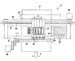
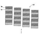
図1は、本発明の実施形態に適用可能なライン型インクジェット記録装置の概略構成を示す斜視図である。
図1において、11は記録に使用するインクを貯留してなるインクタンクであり、このインクタンクには、所定の色材を含有するインクが貯留されている。このインクタンク11に貯留されたインクは、インク供給部12介してラインヘッド(記録ヘッド)17に供給される。ラインヘッド17は、ヘッド保持部材14によって昇降可能に保持され、記録媒体19との対向間隔(以下、紙間と称す)が調整可能になっている。なお、このラインヘッドは、後に図2を用いて詳述するように、記録媒体Pの幅方向(X方向)と直交する方向に沿って、インクを吐出する複数の吐出部(以下、ノズルともいう)を高密度に配列した構成を有している。また、15はラインヘッド17に設けられた各ノズルの吐出口を密閉、開放可能に設けられたキャッピング部材である。このキャッピング部材15は、インク溶剤の蒸発に起因するインクの固着あるいは塵埃などの異物の付着などによる各ノズルの目詰まりを防止する目的で各ラインヘッド毎に設置されている。そして、このキャッピング部材15は、必要に応じてインク吐出口を密閉(キャッピング)し得るよう構成されている。また、記録媒体Pは、不図示の給紙機構によって搬送ローラ18、搬送ベルト16を主な構成要素とする搬送機構に給紙される。この搬送機構およびラインヘッド17は、不図示のコントローラ部によってその動作を制御される。すなわち、ラインクヘッド17は、コントローラ部からフレキシブルケーブル13により送られる吐出データに基づき各ノズルからインクを吐出し、搬送システムは、ラインヘッド17におけるインク吐出動作に同期して記録媒体を搬送する。この記録媒体の搬送動作およびインクの吐出動作によって記録媒体に画像が記録される。
Hereinafter, embodiments of the present invention will be described in detail with reference to the drawings.
FIG. 1 is a perspective view showing a schematic configuration of a line type ink jet recording apparatus applicable to an embodiment of the present invention.
In FIG. 1,
図3は、本発明の実施形態に適用可能なシリアル型インクジェット記録装置の概略構成を示す正面図である。
図において、32はガイドシャフト27およびリニアエンコーダ28によって主走査方向(X方向)に沿って往復移動可能に支持されたキャリッジである。このキャリッジ32は、キャリッジモータ30を駆動し、駆動ベルト29を移動させることにより、ガイドシャフト27に沿って往復移動する。また、キャリッジ32には、複数のインクジェット記録ヘッド(以下、単に記録ヘッドと称する)22が着脱可能に搭載されている。各記録ヘッドには、インクを吐出するための吐出部(以下、ノズルとも言う)が主走査方向に沿って複数配列されている。この記録ヘッド21の各ノズルの内に形成される液路には、液路内のインクを吐出させるための熱エネルギーを発生する発熱素子(電気熱変換体)が設けられている。また、21は、前記各記録ヘッドに所定の色のインクを供給するインクタンクであり、このインクタンク21と、記録ヘッド22とにより、インクカートリッジが構成されている。
FIG. 3 is a front view showing a schematic configuration of a serial type inkjet recording apparatus applicable to the embodiment of the present invention.
In the figure, 32 is a carriage supported by a
また、このシリアル型インクジェット記録装置には、普通紙や高品位専用紙、OHPシート、光沢紙、光沢フィルム、ハガキ等の記録媒体Pを搬送する搬送機構が設けられている。この搬送機構は、不図示の搬送ローラと、排紙ローラ25および、搬送モータ26などを有し、搬送モータ26の駆動に伴い副走査方向(Y方向)に間欠的に搬送される。
Further, this serial type ink jet recording apparatus is provided with a transport mechanism for transporting a recording medium P such as plain paper, high-quality exclusive paper, OHP sheet, glossy paper, glossy film, postcard and the like. This transport mechanism includes a transport roller (not shown), a
上記記録ヘッド22および搬送機構には、後述のコントローラ部から送出される吐出信号および制御信号がフレキシブルケーブル23を介して送られ、その吐出信号および制御信号などに応じて各記録ヘッド22および搬送機構が動作する。
A discharge signal and a control signal sent from a controller unit, which will be described later, are sent to the
すなわち、記録ヘッドの発熱素子は、リニアエンコーダ28から出力されるキャリッジ32の位置信号と、吐出信号とに基づいて駆動され、駆動時に発生する熱エネルギーによってインク滴をノズルから吐出させて記録媒体上に着弾させる。また、搬送機構は、前記制御信号に基づき、記録ヘッドの主走査と主走査との間において記録媒体を副走査方向へと一定量搬送する。この記録ヘッドによる記録動作と搬送機構による搬送動作とを繰り返すことにより、記録媒体全体に画像が形成される。また、記録領域外に設定されたキャリッジ32のホームポジションには、記録ヘッドに形成される吐出口の密閉、開放を可能とするキャップ部35を備えた回復ユニット34が設置されている。
That is, the heating element of the recording head is driven based on the position signal of the
次に、図6を参照しつつ、前述した各インクジェット記録装置の記録ヘッドに設けられる吐出部(ノズル)の構造を説明する。
図6において、記録ヘッド17,22は、インクを加熱するための複数のヒータnbが形成された基板であるヒータボードndと、このヒータボードndの上にかぶせられる天板neとから概略構成されている。天板neには、複数の吐出口naが形成されており、吐出口naの後方には、この吐出口naに連通するトンネル状の液路ncが形成されている。各液路ncは、その後方において1つのインク液室に共通に接続されており、インク液室にはインク供給口を介してインクが供給され、このインクはインク液室からそれぞれの液路ncに供給される。
Next, the structure of the ejection part (nozzle) provided in the recording head of each ink jet recording apparatus described above will be described with reference to FIG.
In FIG. 6, the recording heads 17 and 22 are roughly constituted by a heater board nd, which is a substrate on which a plurality of heaters nb for heating ink are formed, and a top board ne placed on the heater board nd. ing. A plurality of discharge ports na are formed in the top plate ne, and a tunnel-like liquid path nc communicating with the discharge ports na is formed behind the discharge ports na. Each liquid path nc is connected to one ink liquid chamber in common behind it, and ink is supplied to the ink liquid chamber via an ink supply port, and this ink is supplied from the ink liquid chamber to each liquid path nc. To be supplied.
このヒータボードndと天板neとは、各液路ncに各ヒータnbが対応するように位置決めされて接合される。図6においては、4つのヒータnbしか示されていないが、ヒータnbは、夫々の液路ncに対応して1つずつ配置されている。このヒータnbに所定の駆動パルスを供給すると、ヒータnb上のインクが沸騰して気泡を形成し、この気泡の体積膨張により液路nc内のインクが吐出口naから液滴となって吐出される。また、吐出口naと、ヒータnbと、液路ncとにより、ノズル(吐出部)nが構成されている。 The heater board nd and the top plate ne are positioned and joined so that each heater nb corresponds to each liquid path nc. In FIG. 6, only four heaters nb are shown, but one heater nb is arranged corresponding to each liquid path nc. When a predetermined drive pulse is supplied to the heater nb, the ink on the heater nb boils to form bubbles, and the ink in the liquid path nc is discharged as droplets from the discharge port na due to the volume expansion of the bubbles. The Further, the discharge port na, the heater nb, and the liquid path nc constitute a nozzle (discharge portion) n.
なお、本発明に適用可能なインクジェット記録方式は、図6に示したような発熱素子(ヒータ)を使用した方式に限定されるものではない。例えば、インク滴を連続噴射し粒子化するコンティニュアス型のインクジェット方式であれば、荷電制御型、発散制御型等が適用可能である。また、必要に応じてインク滴を吐出するオンデマンド型のインクジェット記録方式であれば、ピエゾ振動素子の機械的振動により吐出口からインク滴を吐出する圧力制御方式等が適用可能である。 The ink jet recording method applicable to the present invention is not limited to the method using a heating element (heater) as shown in FIG. For example, a charge control type, a divergence control type, and the like can be applied to a continuous ink jet system that continuously ejects ink droplets into particles. In addition, as long as it is an on-demand type ink jet recording system that ejects ink droplets as necessary, a pressure control system that ejects ink droplets from ejection ports by mechanical vibration of a piezoelectric vibration element can be applied.
図7は本実施形態におけるインクジェット記録装置の制御系の一構成例を示すブロック図である。
図7において、71はホストコンピュータなどをはじめとする外部機器80から送信される画像データおよび制御データなどを受信するデータ入力部、72はデータ入力あるいは設定操作などを行う操作部である。また、73は各種の情報処理および制御動作を行うCPU、74は各種データを記憶する記憶媒体である。この記憶媒体74には、記録媒体の主に種類に関する情報、インクに関する情報、記録時の温度、湿度などの環境に関する情報などの画像記録情報、を格納する記録情報格納部74a、および各種制御プログラム群を格納するプログラム格納部74bなどを含む。さらに、75はCPU72の処理データや入力データなどを一時的に格納するRAM、76は入力された画像データに対して色変換、二値化処理などを含む所定の画像処理を行う画像データ処理部である。また、77は記録ヘッドや搬送機構などによって画像出力を実行する画像記録部、78は本装置内のアドレス信号、データ、制御信号などを伝送するバスラインである。
FIG. 7 is a block diagram illustrating a configuration example of a control system of the ink jet recording apparatus according to the present embodiment.
In FIG. 7,
より具体的に説明すると、外部機器80としては、例えば、スキャナやデジタルカメラなどの画像入力機器、あるいはパーソナルコンピュータなどがある。このスキャナやデジタルカメラ等から出力される多値画像データ(例えば、RGBの8bitデータ)やパーソナルコンピュータのハードディスク等に保存されている多値画像データは画像データ入力部71に入力される。また、操作部72は各種パラメータの設定および記録開始指示の入力などを行うための各種キーが備えられている。CPU73は記憶媒体中の各種プログラムに従ってインクジェット記録装置全体の制御を行う。記憶媒体74に格納されるプログラムとしては、制御プログラムやエラー処理プログラムに従ってインクジェット記録装置を動作させるためのプログラムがあり、本実施形態の動作は全てこのプログラムに従って実行される。また、このプログラムを格納する記憶媒体74としては、ROM、FD、CD−ROM、HD、メモリカード、光磁気ディスクなどが使用可能である。RAM75は、記憶媒体74に格納される各種プログラムを実行する際のワークエリア、エラー処理時の一時待避エリア及び画像処理時のワークエリアとして用いられる。また、RAM75では、記憶媒体74の中の各種テーブルをコピーした後、そのテーブルの内容を変更し、この変更したテーブルを参照しながら画像処理を進めることも可能である。
More specifically, the
画像処理部76は、入力された多値画像データ(例えば、8bitのRGBデータ)を画素毎に各インク色の多値データ(例えば、8bitのCMYBkデータ)に変換する色分解処理を行う。さらに、その各色の多値データをK値(例えば、17値)のデータに各画素毎に量子化し、その量子化された各画素が示す階調値“K”(階調値0〜16)に対応するドット配置パターンを設定する処理を行う。なお、ここではK値化処理には多値誤差拡散法を用いているが、これに限定されるものではなく、平均濃度保存法、ディザマトリックス法等、任意の中間調処理方法などを用いることも可能である。また、前述のK値化処理を行った後は、それぞれの階調を後述のドット配置パターン(このパターンは、ドット集中型からなる画像の単位形状INDEXと称されることがある)に対応させるドット配置パターン化処理を行う。そして、記録ヘッドによる複数回の記録走査において、ドット配置パターン化処理によって生成された2値の記録データに対し、間引きマスクパターンにより各記録走査に記録データを分配する間引き処理を行う。なお、前記の記録ヘッドによる複数回の記録走査には、2列以上のノズル列を有する記録ヘッドによって行われる1回の記録走査も含まれる。
これら処理を繰り返すことにより、記録ヘッドの各ノズルに対する吐出、不吐出を表す2値の記録データが作成される。そして、画像記録部77は、画像データ処理部76で作成された2値の記録データに基づいてインクを吐出し、記録媒体上にドット画像を形成する。
The
By repeating these processes, binary recording data representing ejection and non-ejection for each nozzle of the recording head is created. The
次に、上記各インクジェット記録装置に用いられる記録ヘッドに設けられるノズルの配列状態を、図2、図4および図5に基づき説明する。
図2は、図1に示すフルライン型インクジェット記録装置に用いられる記録ヘッド(ラインヘッド)17のノズルの配列状態を示す図である。
図2において、この記録ヘッド17は、複数本(ここでは4本)のノズル列17A,17B,17C,17Dを記録媒体の搬送方向(Y方向)に並設してなる。各ノズル列は、同一の構成を有し、いずれも2本の中ノズル列を連結した所謂つなぎヘッドとなっている。すなわち、ノズル列17Aは、中ノズル列171と中ノズル列175とからなる。また、ラインクヘッド17Bは、中ノズル列172と中ノズル列176とからなる。また、ラインヘッド17Cは、中ノズル列173と中ノズル列177とからなる。さらに、ラインヘッド17Dは、中ノズル列174と中ノズル列177とからなる。
Next, the arrangement state of the nozzles provided in the recording head used in each of the ink jet recording apparatuses will be described with reference to FIG. 2, FIG. 4, and FIG.
FIG. 2 is a diagram showing an arrangement state of nozzles of a recording head (line head) 17 used in the full line type ink jet recording apparatus shown in FIG.
In FIG. 2, the
また、各ラインヘッドを構成する各ノズル列17A,17B,17C,および17Dは、次のような構成を有する。なお、各ノズル列はいずれも同一の構成を有するため、以下の説明では、ノズル列17Aを例に採り説明する。
Each
ノズル列17Aを構成する中ノズル列171は、複数(ここでは4本)の小ノズル列NG1〜NG4によって構成されている。これらの小ノズル列は、千鳥状に配置されている。さらに、各小ノズル列は、平均2.5plのインク液滴を吐出する複数のノズルnを千鳥状に配列することにより、副走査方向におけるノズルの配列密度を高密度化した構成となっている。また、ノズル列171内の隣接する小ノズル列は、互いに端部がオーバーラップしており、ノズル列全体として一定の配列密度が得られるようになっている。この実施形態では、ノズル列171におけるノズルの配列密度は1200dpiとなっている。
The
このように構成されたノズル列は、4個の小ノズル列、すなわち一つの中ノズル列によって略4インチ幅の記録を一記録走査で行うことが可能であり、さらに、ラインヘッド全体では、各ノズル列171,175により略8インチ幅の記録が可能になっている。なお、他のラインヘッド17C,17B,17Dも同様の構成を有している。
The nozzle array configured in this manner can perform recording of approximately 4 inches width by one recording scan by four small nozzle arrays, that is, one middle nozzle array. The
また、図2では、4個のノズル列が副走査方向(Y方向)に並設されているラインヘッドを示したが、本発明は上記のような構成を有するラインヘッドに限らず、その他の構成を有するラインヘッドを用いることも可能である。例えば、同一のノズルから大小のインク滴を吐出させることを可能とするものであっても良いし、また濃インクと淡インクを吐出可能なものであってもよい。また4列に限らず、その他の本数のノズル列を並設したものでもよい。 2 shows a line head in which four nozzle rows are arranged in parallel in the sub-scanning direction (Y direction), the present invention is not limited to the line head having the above-described configuration, It is also possible to use a line head having a configuration. For example, it may be possible to eject large and small ink droplets from the same nozzle, or it may be capable of ejecting dark ink and light ink. Further, the number of nozzle rows is not limited to four, and other numbers of nozzle rows may be provided in parallel.
次に、図4および図5に基づき、図3に示すシリアル型インクジェット記録装置に用いる記録ヘッドの構成例を説明する。
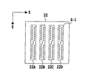
図4に示す記録ヘッド22は、4本のノズル列22A、22B、22Cおよび22Dが、単一の記録ヘッド構成部材に並設された構成を有している。各ノズル列には、複数のノズルnが一定の配列方向(Y方向)に沿って千鳥状に高密度に配列されている。この記録ヘッドにおいては、各ノズル列の配列密度は1200dpi、各ノズルの平均インク滴量は2.5plとなっている。
Next, a configuration example of a recording head used in the serial type ink jet recording apparatus shown in FIG. 3 will be described with reference to FIGS.
The
また、記録ヘッド22がキャリッジ32に装着された状態で、複数のノズルの配列方向は、記録媒体の搬送方向である副走査方向(Y方向)と一致する。従って、記録ヘッド22の走査方向は、この副走査方向と直交するX方向となる。
In the state where the
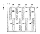
一方、図5に示す記録ヘッド22も、図4に示す記録ヘッドと同様に、4本のノズル列22A、22B、22C、および22Dが、単一の記録媒体構成部材に並設された構成を有している。
On the other hand, the
但し、図5に示す記録ヘッド22では、各ノズル列が、いずれも2本の小ノズル列を連結した比較的長尺なノズル列となっている。すなわち、ノズル列22Aは、小ノズル列2211と小ノズル列225とからなる。ノズル列22Bは、小ノズル列222と小ノズル列226とからなる。ノズル列22Cは小ノズル列223と小ノズル列227とからなる。ノズル列22Dは、小ノズル列224と小ノズル列228とからなる。また、各ノズル列を構成する2本の小ノズル列は、互いに端部がオーバーラップした状態で配置されている。
However, in the
さらに、各小ノズル列は、平均2.5plのインク液滴を吐出する複数のノズルnをY方向に沿って千鳥状に配列することにより、副走査方向(Y方向)におけるノズルの配列密度を高密度化した構成となっている。なお、この図5に示す記録ヘッド22においても、各ノズル列におけるノズルの配列密度は、1200dpiとなっている。
Furthermore, each small nozzle row arranges a plurality of nozzles n that eject ink droplets of an average of 2.5 pl in a staggered manner along the Y direction, thereby reducing the nozzle arrangement density in the sub-scanning direction (Y direction). It has a high density configuration. In the
なお、図4および図5に示す記録ヘッドにおいても、図3に示すように、各ノズル列毎に記録ヘッドを構成し、それらを個々に着脱可能とすることも可能である。 4 and 5, it is also possible to form a recording head for each nozzle row and make them detachable individually as shown in FIG.
次に、本発明の特徴的部分である間引き分割記録の実施形態について説明する。
この実施形態では、所定の幅を持つ低記録率領域(高間引き率領域)と高記録率領域(低間引き率領域)とを有するマスクパターンを用いて記録データを間引くことにより、記録ヘッドの各ノズルに記録データを分配する。これは、この実施形態の特徴的構成の一つである。
Next, an embodiment of thinning division recording, which is a characteristic part of the present invention, will be described.
In this embodiment, by thinning out print data using a mask pattern having a low print rate area (high thinning rate area) and a high print rate area (low thinning rate area) having a predetermined width, Distribute the recording data to the nozzles. This is one of the characteristic configurations of this embodiment.
まず、本発明者らが鋭意検討を重ねた結果、本発者らが見い出した本発明の原理について以下に述べる。
図3に示すようなシリアル型のインクジェット記録装置において、記録ヘッド22の走査を行うキャリッジ32の走査速度が遅い場合、あるいはノズルが150dpi程度の極めて低い密度で配列されている場合には、ノズル列内に発生する乱流は弱い。しかし、ノズルが600dpi以上の高密度で配列され、かつ高速で高記録率の画像を記録すると、強い乱流が発生する。
First, the principle of the present invention found out by the present inventors as a result of extensive studies by the present inventors will be described below.
In the serial type ink jet recording apparatus as shown in FIG. 3, when the scanning speed of the
これは次のような実験から確認された。すなわち、記録ヘッド22と記録媒体Pとの距離間隔を0.5mmから3.0mm程度に設定し、記録ヘッド22と記録媒体Pとの相対走査速度が5inch/s(sec)を超えるような高速で主走査を行った。この際、6pl以下の小液滴を吐出するノズルを600dpi程度の高密度に配列したノズル列を有する記録ヘッドを使用した場合には、ノズル列の中で同時にインク滴を吐出する領域幅が広いと、乱流が強く発生し、着弾精度が著しく劣化することが観察された。
This was confirmed by the following experiment. In other words, the distance between the
この場合、普通紙に代表されるように紙面が比較的粗な記録媒体では、着弾したインク滴の拡散(滲み)が大きいことから、ある程度の着弾位置の変動は画質として許容される範囲にある。しかし、コート紙や光沢紙のように滲みの少ない記録媒体に記録を行う場合には、着弾位置の乱れが顕在化し、濃度むらとして認識され易い。 In this case, in a recording medium having a relatively rough paper surface as represented by plain paper, the landing ink droplets have a large diffusion (bleeding), and therefore, a certain amount of variation in the landing position is within the allowable range for image quality. . However, when recording is performed on a recording medium with less bleeding such as coated paper or glossy paper, the landing position is disturbed and is easily recognized as density unevenness.
上記のように実験を繰り返した結果、インクジェット記録装置において画像劣化が顕著に現れる記録条件は以下のようであることが確認された。 As a result of repeating the experiment as described above, it was confirmed that the recording conditions in which the image deterioration appears remarkably in the ink jet recording apparatus are as follows.
すなわち、
(1) 記録ヘッドのノズル列が600dpi以上の密度で略一列(ここで、略一列とは、図3や図9等に示される千鳥配置も含む)に配置されていること、
(2) ノズルからのインク滴の量が6pl以下の小液滴であること、
(3) 記録ヘッドと記録媒体の相対移動速度、すなわち記録走査速度が5inch/s以上であること、
(4) 記録ヘッドと記録媒体との距離間隔が0.5mm以上であること
等が挙げられる。
That is,
(1) The nozzle rows of the recording head are arranged in a substantially single row with a density of 600 dpi or more (here, the substantially one row includes the staggered arrangement shown in FIGS. 3 and 9).
(2) The amount of ink droplets from the nozzle is a small droplet of 6 pl or less,
(3) The relative movement speed of the recording head and the recording medium, that is, the recording scanning speed is 5 inches / s or more,
(4) The distance between the recording head and the recording medium is 0.5 mm or more.
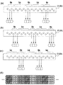
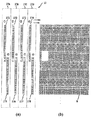
さらに、1回の主走査中における記録率が高いことほど画像の劣化が顕著になるということも確認した。図9はその際のインク液滴の着弾の様子を模式的に示したものである。 Furthermore, it was also confirmed that the higher the recording rate during one main scan, the more noticeable the deterioration of the image. FIG. 9 schematically shows how ink droplets land at that time.
図9Aは1200dpiの密度でノズルを略一列に配列したノズル列からインク滴を吐出した際の、インク滴の飛翔方向および記録媒体上に形成されたドットの様子を示している。このときの記録条件は、次のように設定した。
記録ヘッドと記録媒体との相対移動速度(記録走査速度)は2.5inch/sという非常に低速に設定した。各ノズルの駆動周波数は3kHzに設定した。記録率は100%(ノズル列の全てのノズルから吐出させた状態)に設定した。記録ヘッドと記録媒体との離間距離は0.4mmに設定した。
このような記録条件において、図示のように、各ノズル列から吐出されたインク滴は、図中の矢印に示すように、略同一方向へと飛翔するため、インク滴の着弾位置に乱れが生じることはなく、濃度むらのない画像が形成された。
FIG. 9A shows the flying direction of ink droplets and the state of dots formed on a recording medium when ink droplets are ejected from a nozzle row in which nozzles are arranged in approximately one row at a density of 1200 dpi. The recording conditions at this time were set as follows.
The relative movement speed (recording scanning speed) between the recording head and the recording medium was set to a very low speed of 2.5 inches / s. The drive frequency of each nozzle was set to 3 kHz. The recording rate was set to 100% (state in which ejection was performed from all nozzles in the nozzle row). The separation distance between the recording head and the recording medium was set to 0.4 mm.
Under such recording conditions, as shown in the figure, the ink droplets ejected from each nozzle row fly in substantially the same direction as indicated by the arrows in the figure, and therefore, the landing positions of the ink droplets are disturbed. There was nothing, and an image having no uneven density was formed.
一方、図9Bは、記録条件として、記録走査速度を15inch/sという高速に設定すると共に、記録ヘッドと記録媒体との距離間隔を1.5mmに設定し、その他の条件は図9Aと同様にしてインク液滴を吐出した状態を示している。
この場合、記録ヘッドと記録媒体の間に乱流が生じ、その結果、ノズルから吐出されたインク滴の飛翔方向は不均一になり、着弾位置に乱れが生じた。この着弾位置の乱れにより、形成される画像には濃度むらや白スジ、黒スジが発生した。
On the other hand, in FIG. 9B, the recording scanning speed is set to a high speed of 15 inches / s as the recording conditions, the distance between the recording head and the recording medium is set to 1.5 mm, and the other conditions are the same as in FIG. 9A. In this state, ink droplets are ejected.
In this case, a turbulent flow is generated between the recording head and the recording medium. As a result, the flying directions of the ink droplets ejected from the nozzles are non-uniform, and the landing position is disturbed. Due to the disturbance of the landing position, density unevenness, white stripes, and black stripes occurred in the formed image.
図9Cは、図9Aおよび図9Bと同様のノズル列において、3ノズル幅の領域HNと6ノズル幅の領域LNとを交互に設定した場合を示している。ここで、3ノズル幅の領域HNは高記録率で記録する高記録率領域とし、6ノズル幅の領域LNは低記録率で記録する低記録率領域としている。この場合、記録走査速度を15inch/sという高速に設定しても、インク液滴の着弾位置に乱れが生じることはなかった。 FIG. 9C shows a case where the 3-nozzle-width region HN and the 6-nozzle-width region LN are alternately set in the same nozzle row as in FIGS. 9A and 9B. Here, the region HN having a width of 3 nozzles is a high recording rate region for recording at a high recording rate, and the region LN having a width of 6 nozzles is a low recording rate region for recording at a low recording rate. In this case, even when the recording scanning speed was set to 15 inches / s, the landing position of the ink droplets was not disturbed.
図10は、1200dpiの密度で配列されたノズル列の中に、前述の図9Cと同様に、6ノズル幅の低記録率領域Lnと3ノズル幅の高記録率領域Hnとを交互に設定し、3回の走査記録を繰り返して画像を形成する様子を示している。図10Aは、第1走査時に吐出されたインク滴の飛翔状態および記録媒体への着弾状態を示している。図10Bは第2走査時に吐出されたインク滴の飛翔状態および記録媒体への着弾状態を示している。図10Cは第3走査時に吐出されたインク滴の飛翔状態および記録媒体への着弾状態を示している。図10Dは、図10A〜図10Cの計3回の走査によるドット形成状態を示している。 In FIG. 10, in the nozzle array arranged at a density of 1200 dpi, similarly to the above-described FIG. 9C, a low recording rate region Ln with 6 nozzles and a high recording rate region Hn with 3 nozzles are alternately set. It shows a state in which an image is formed by repeating scanning and recording three times. FIG. 10A shows the flying state of the ink droplets ejected during the first scan and the landing state on the recording medium. FIG. 10B shows the flying state of the ink droplets ejected during the second scanning and the landing state on the recording medium. FIG. 10C shows the flying state of the ink droplets ejected during the third scan and the landing state on the recording medium. FIG. 10D shows a dot formation state by a total of three scans of FIGS. 10A to 10C.
図10に示すように、この場合にもインクの着弾位置に乱れは生じず、良好な画像を形成することができる。なお図10に示す例では、便宜上、低記録率領域からインク吐出を行わない場合を示しているが、吐出を全く行わないことは、記録条件として必須ではなく、比率として低ければ同様の効果があることも別途確認している。また図10では、便宜上、高記録率領域から全吐出(100%の記録率)を行う場合を示しているが、低記録比率の吐出の状態に応じて比率を変えたりすることも可能である。なお、ノズル列内の記録率の高低は、記録データを間引くためのマスクパターンMの間引き率の高低に依存する。従って、ノズル列内の高記録率領域Hmに対応するマスクパターンの間引き率は低く設定され、ノズル列内の低記録率領域Lmに対応するマスクパターンの間引き率は高く設定されている。 As shown in FIG. 10, even in this case, the ink landing position is not disturbed, and a good image can be formed. In the example shown in FIG. 10, for convenience, the case where ink is not ejected from the low recording rate area is shown. However, it is not essential as a recording condition that ejection is not performed at all. It is also confirmed that there is. For convenience, FIG. 10 shows a case in which all ejections (100% recording rate) are performed from the high recording rate area, but the ratio can be changed according to the ejection state of the low recording rate. . Note that the level of the recording rate in the nozzle row depends on the level of the thinning rate of the mask pattern M for thinning out the recording data. Accordingly, the thinning rate of the mask pattern corresponding to the high recording rate region Hm in the nozzle row is set low, and the thinning rate of the mask pattern corresponding to the low recording rate region Lm in the nozzle row is set high.
図11ないし図15は、上述のようにノズル列内に高記録率領域Hnと低記録率領域Lnとを交互に設定するよう、記録データに対する間引き処理を行うためのマスクパターンを概念的に示した図である。
図11に示すマスクパターン110は、低記録率領域(高間引き率領域)Lmと、高記録率領域(低間引き率領域)Hmと、を交互に配列したパターンとなっている。低記録率領域(高間引き率領域)は、前述の画像処理部76で2値化された記録データを、高い間引き率で間引く領域である。また、高記録率領域(低間引き率領域)Hmは、前記2値化された記録データを低い間引き率で間引く領域である。この各領域Lm,Hmは、主走査方向に沿って直線的に延在する短冊状の領域となっている。
FIGS. 11 to 15 conceptually show mask patterns for performing thinning processing on print data so as to alternately set the high print rate area Hn and the low print rate area Ln in the nozzle row as described above. It is a figure.
A
なお、マスクパターンの間引き率とは、予め定めた記録許容エリアと非記録エリアとで構成されるマスクパターンの全エリアのうち、間引く箇所を示す非記録エリアが占める割合を指す。一方、マスクパターンの記録率とは、予め定めた記録許容エリアと非記録エリアとで構成されるマスクパターンの全エリアのうち、記録許容エリアが占める割合を指し、マスクパターンの記録率と間引き率とは逆の意である。よって、前述の低間引き率領域と高記録率領域、高間引き率領域と低間引き率領域、はそれぞれ同じ意を表わす。また、マスクパターンの間引き率および記録率は予め定められた値であり、いずれも画像データに影響される値ではない。 The mask pattern thinning rate refers to the ratio of the non-recording area indicating the thinned-out portion of the total area of the mask pattern composed of a predetermined recording allowable area and a non-recording area. On the other hand, the mask pattern recording rate refers to the ratio of the recording allowable area to the total area of the mask pattern composed of the predetermined recording allowable area and the non-recording area. The mask pattern recording rate and the thinning rate The opposite is true. Therefore, the low thinning rate region and the high recording rate region, and the high thinning rate region and the low thinning rate region have the same meaning. Further, the thinning rate and recording rate of the mask pattern are predetermined values, and neither is a value affected by the image data.
このマスクパターン110を用いれば、図2、4、5に示すような高密度にノズルを配置したノズル列の記録ヘッドを高速走査して記録を行った場合にも、図9Cおよび図10に示すような良好なインク滴の飛翔状態を得ることができる。これにより、着弾誤差の少ない良好な画像を形成することができる。
When this
例えば、マスクパターン110によって記録データを間引くことにより、ノズル列は、図9Cおよび図10に示すような状態となる。すなわち、ノズル列は、吐出されるインク滴の数が傾向的に多くなる領域(高記録率領域)Hnと、吐出されるインク滴の数が傾向的に少なくなる領域(低記録率領域)Lnとに交互に分割された状態となる。換言すれば、高記録率領域Hnのノズル列方向における幅は、低記録率領域Lnによって分割された状態となる。これにより、記録ヘッドと記録媒体との間隙に発生する乱流レベルが低減されると共に、着弾位置の変動はノズル列全体に亘って均一化され、良好な品質の画像を得ることができる。
For example, by thinning the print data with the
ここで、高間引き率領域と低間引き率領域とが交互に配列されたマスクパターンを用いることよって、上述した着弾位置のズレが低減する理由(メカニズム)について、本発明者の推測であるが説明する。
シリアル方式やフルライン方式のインクジェットプリンタにおいて、短時間で画像を完成させるためには、高い記録率で高速な相対走査を行うことが必要となる。この際、記録ヘッドと記録媒体との隙間に気流の乱れが生じることは上述した通りである。この気流の発生量と乱れ方は走査速度や記録率に大きく依存するが、マスクパターンにおける間引き率分布を本発明の如く構成することで上記気流の乱れが抑制される。
すなわち、記録ヘッドと記録媒体との高速な相対走査によって、相対走査方向における記録ヘッド先頭側から後続側に大きな気流が発生する。これが前述した記録ヘッドと記録媒体との隙間に生じる気流である。この気流に略直交する方向に対して記録ヘッドからインク滴が高密度で吐出されるが、この高密度なインク吐出によって前記気流に乱れが生じる。具体的には、高密度な吐出インクの壁を迂回するように気流が生じる。すると、この迂回気流によってインク滴の吐出方向が変化し、これが着弾位置ズレに繋がる。
ところが、ノズル配列方向の間引き率が高、低、高、低のように交互に配されたマスクパターンを用いると、高密度な吐出インクの壁に隙間が生じることになる。具体的には、マスクパターンの高間引き率領域に対応する箇所が前記隙間となることから、吐出インクの壁にはノズル配列方向に交互の隙間が生じる。すると、この隙間から気流が抜け、その分、迂回する気流の量が減り、結果的に、この迂回気流による着弾位置ズレも抑制される。
Here, although the reason (mechanism) of reducing the above-described displacement of the landing position by using the mask pattern in which the high thinning rate region and the low thinning rate region are alternately arranged is the inventor's estimation, To do.
In order to complete an image in a short time in a serial type or full line type inkjet printer, it is necessary to perform high-speed relative scanning at a high recording rate. At this time, as described above, the turbulence of the airflow occurs in the gap between the recording head and the recording medium. The amount of the generated air flow and how it is disturbed largely depend on the scanning speed and the recording rate, but the air flow disturbance is suppressed by configuring the thinning rate distribution in the mask pattern as in the present invention.
That is, a large air flow is generated from the recording head head side to the subsequent side in the relative scanning direction by high-speed relative scanning between the recording head and the recording medium. This is the airflow generated in the gap between the recording head and the recording medium described above. Ink droplets are ejected at a high density from the recording head in a direction substantially perpendicular to the air flow, but the air current is disturbed by the high density ink ejection. Specifically, an air flow is generated so as to bypass the wall of the high density discharged ink. Then, the discharge direction of the ink droplets is changed by the detour airflow, which leads to the landing position deviation.
However, if mask patterns arranged alternately such that the thinning rate in the nozzle arrangement direction is high, low, high, and low are used, gaps are generated in the walls of high-density ejected ink. Specifically, the portion corresponding to the high thinning rate region of the mask pattern becomes the gap, and therefore, an alternating gap is generated in the nozzle arrangement direction on the wall of the ejected ink. As a result, the airflow is removed from the gap, and the amount of the detour airflow is reduced accordingly. As a result, the landing position deviation due to the detour airflow is also suppressed.
なお、記録ヘッドの一回の走査によって形成される画像は、記録データにもよるが、傾向的には、図11に示すマスクパターンに対応して高記録率にて記録される領域と低記録率にて記録される領域とが交互に形成される。
図3に示すようなシリアル型のインクジェット記録装置では、高記録領域と低記録領域との位置を変更した複数の相補的なマスクパターンを用意しておき、これを各走査毎に切換えて同一色の記録ヘッドに供給する。これにより、同一の走査領域に対し複数回の記録走査で同一色の画像を完成することができる。
Note that the image formed by one scan of the recording head depends on the recording data, but it tends to correspond to the mask pattern shown in FIG. Areas recorded at a rate are alternately formed.
In the serial type ink jet recording apparatus as shown in FIG. 3, a plurality of complementary mask patterns in which the positions of the high recording area and the low recording area are changed are prepared, and this is switched for each scan. To the recording head. As a result, an image of the same color can be completed by a plurality of recording scans for the same scanning area.
図1に示すようなフルライン型の記録装置において、上記マスクパターンを用いて記録動作を行う場合には、同一色のインクを吐出する複数本のノズル列を有するラインヘッドを設けると共にシリアルプリンタと同様に相補的な複数種のマスクパターンを用意する。そして、各マスクパターンによって間引かれた画像データを各ノズル列に供給して記録動作を行う。これにより、同一の記録領域に対し実質的に複数回の走査が行われて同一色の画像が完成する。 In a full-line type recording apparatus as shown in FIG. 1, when a recording operation is performed using the mask pattern, a line head having a plurality of nozzle arrays for ejecting ink of the same color is provided and a serial printer is provided. Similarly, a plurality of complementary mask patterns are prepared. Then, the image data thinned out by each mask pattern is supplied to each nozzle row to perform a recording operation. Thus, the same recording area is substantially scanned a plurality of times to complete the same color image.
図12に示すマスクパターン120は、図11に示すマスクパターン110と同様に、短冊状をなす低記録率領域Lmと高記録率領域Hmとを交互に配列したパターンとなっている。しかし、ここに示すマスクパターンは、高記録率領域Hmと低記録率領域Lmとの境界が、連続的にノズルの配列方向に変化している(うねっている)ものとなっている。この場合には、図11に示したものと同様に、気流による画質劣化を低減することができる。さらに、一回の走査において、ノズル列の中の一つのノズルが高記録率による記録と、低記録率による記録とを行うことになるため、ノズルの使用頻度を均一化することが可能となる。このため、このマスクパターン120には、各ノズルの寿命を均一化でき、記録ヘッド全体の寿命を高めることができるという利点がある。また、上記のように短冊状の各領域に波形のうねりを持たせることにより、各領域間にスジむらが発生するのを低減することができる。
A
また、記録ヘッドが斜めに取り付けられていると、一般には、形成される画像に筋むらが発生する懸念がある。しかし、この問題は、ヘッドの取り付け精度を高めることで解消される。特にフルマルチ型ラインプリンターではヘッドをプリント装置に固定し、被記録媒体を搬送するため、シリアルタイプに比べて印字に対する影響は少ない。 In addition, when the recording head is attached obliquely, there is generally a concern that unevenness occurs in the formed image. However, this problem can be solved by increasing the head mounting accuracy. In particular, in the full multi-line printer, the head is fixed to the printing apparatus and the recording medium is conveyed, so that the influence on printing is small compared to the serial type.
図13に示すマスクパターン130は、低記録率領域Lmおよび高記録率領域Hmのノズル列方向における幅を不等間隔に構成した例を示している。また、ここでは、2回の記録走査で同一の記録領域における画像を完成させる場合に用いるマスクパターンを示している。図中130aは、第1回目の走査において用いるマスクパターンを、130bは第2回目の走査において用いられるマスクパターンをそれぞれ示している。
この場合においても高記録率領域の幅が所定の領域幅以下であれば、記録ヘッドと記録媒体との間に発生する乱流を軽減することができるため、良好な画像を形成することができる。また、ノズル列が比較的長尺になるとノズル列内に対応する位置で、記録媒体との間に気流の分布が生じるため高記録比率の領域幅はノズル列内の位置に応じて設計することが好ましい。
The mask pattern 130 shown in FIG. 13 shows an example in which the widths in the nozzle row direction of the low recording rate region Lm and the high recording rate region Hm are configured at unequal intervals. Here, a mask pattern used when an image in the same recording area is completed by two recording scans is shown. In the figure, 130a indicates a mask pattern used in the first scan, and 130b indicates a mask pattern used in the second scan.
Even in this case, if the width of the high recording rate area is equal to or smaller than the predetermined area width, a turbulent flow generated between the recording head and the recording medium can be reduced, so that a good image can be formed. . Also, if the nozzle row is relatively long, an air flow distribution occurs at a position corresponding to the nozzle row, and the area width of the high recording ratio should be designed according to the position in the nozzle row. Is preferred.
図14は、4回の記録走査で画像を完成させる場合に用いられるマスクパターンを示している。この場合においても高記録率領域幅が所定の領域幅以下でれば、気流による悪影響を受けにくくすることができ、良好な画像を形成できる。
また4回の走査で同一の記録領域に対する記録を完成させる場合(記録率100%の記録を行う場合)、各走査を均等の記録率で記録する場合には、各走査における記録率は、25%になる。このため、上記のように高記録率領域の幅を非常に狭い幅に設定したマスクパターンを用いなくとも乱流によるインク滴への影響が少なくなる場合がある。しかしながら図15のように、高記録率領域の幅を広く設定すると視覚的に認識し易いピッチで濃度むらが現れ易いので望ましくない。
FIG. 14 shows a mask pattern used when an image is completed by four recording scans. Even in this case, if the high recording rate area width is equal to or smaller than the predetermined area width, it is possible to make it difficult to be adversely affected by the air current, and a good image can be formed.
In addition, when recording in the same recording area is completed by four scans (when recording is performed at a recording rate of 100%), when recording is performed at an equal recording rate, the recording rate in each scan is 25. %become. For this reason, there is a case where the influence of the turbulent flow on the ink droplets is reduced without using a mask pattern in which the width of the high recording rate area is set to a very narrow width as described above. However, as shown in FIG. 15, if the width of the high recording rate area is set wide, it is not desirable because density unevenness tends to appear at a pitch that can be visually recognized easily.
さらに、多くの記録走査で画像を完成させる場合には、上述の理由により、一回の走査における記録率が低くなり、乱流があまり発生しないため、上記のような短冊状の高記録率領域を設定する必要がない場合もある。すなわち、本発明は、記録マトリックスが600dpi以上の解像度であり、4回以下程度の走査回数で画像を完成させようとした場合に有効である。特に、より顕著な効果が現れるのは、2回の走査で画像を完成させる場合である。これは、シリアル型のインクジェット記録装置に限らず、前述のようにフルライン型のインクジェット記録装置で同色インクを吐出するノズル列が2列以上並設され、各ノズル列によって同一色の画像を完成させる場合も同様である。 Further, when an image is completed by many recording scans, the recording rate in one scanning is low and turbulent flow is not generated for the above-described reason. You may not need to set That is, the present invention is effective when the recording matrix has a resolution of 600 dpi or higher and an image is to be completed with the number of scans of about 4 or less. In particular, a more prominent effect appears when an image is completed by two scans. This is not limited to the serial type ink jet recording apparatus, and as described above, the full line type ink jet recording apparatus has two or more nozzle rows that discharge the same color ink in parallel, and each nozzle row completes the same color image. The same applies to the case.
以上のように、本発明者らは鋭意検討を重ねた結果、同一の記録走査において周期的、非周期的に拘わらず高記録比率領域と低記録率領域とを交互に出現させると共に、高記録率領域を所定の領域幅以下に配列することが有効であることが確認された。すなわち上記のように記録比率を設定すれば、高密度にノズルを配置した記録ヘッドを用いて高速記録を行う場合にも、記録ヘッドと記録媒体との間に生じる乱流は低減され、着弾位置の変動がノズル列全体に亘って低減されることを実験的に確認することができた。また、高記録比率領域の短冊幅を広くすると、高記録領域の内部で乱流が発生し画質を維持できなくなることも確認できた。さらに、乱流による影響を軽減するという観点からすると、低記録率領域の短冊幅は広いほうが望ましいが、低記録率領域を広げた場合には、必然的に画像を完成させるための記録走査の回数を増すことが必要となる。このため、低記録率領域の幅は適度な広さに設定することが望ましい。例えば2回の記録走査で完成させる場合には、ノズル列内の低記録率領域の合計が高記録率領域の合計と同等であることが求められる。また画像を間引き分割して完成させることが必要であるため、本発明では、低記録率領域の幅の合計が高記録率領域の幅と合計と同等となるように複数回の記録走査(マルチパスによる複数走査あるいは多ヘッドによる複数走査)を行うことが必要となる。 As described above, as a result of intensive studies, the present inventors have made the high recording ratio area and the low recording ratio area appear alternately in the same recording scan regardless of the periodicity or aperiodicity, and the high recording ratio. It has been confirmed that it is effective to arrange the rate regions within a predetermined region width. In other words, if the recording ratio is set as described above, turbulence generated between the recording head and the recording medium is reduced even when high-speed recording is performed using a recording head having nozzles arranged at high density, and the landing position is reduced. It can be experimentally confirmed that the fluctuation of is reduced over the entire nozzle array. It was also confirmed that when the strip width of the high recording ratio area is widened, turbulence is generated inside the high recording area and the image quality cannot be maintained. Furthermore, from the viewpoint of reducing the influence of turbulent flow, it is desirable that the strip width of the low recording rate area is wide. However, when the low recording rate area is widened, it is necessary to perform recording scanning to inevitably complete an image. It is necessary to increase the number of times. For this reason, it is desirable to set the width of the low recording rate area to an appropriate width. For example, when the printing is completed by two printing scans, the total of the low printing rate areas in the nozzle row is required to be equal to the total of the high printing rate areas. In addition, since it is necessary to complete the image by thinning and dividing the image, in the present invention, a plurality of printing scans (multiple scans) are performed so that the total width of the low recording rate area is equal to the total width of the high recording rate area. It is necessary to perform multiple scans by passes or multiple scans by multiple heads).
さらに実験によって確かめられた結果について詳説する。
ノズルの配列密度が600dpiである記録ヘッドを用い、記録ヘッドと記録媒体との間隔を1.5mmに設定し、かつ15inch/sの走査速度で記録動作を行った。
In addition, the results confirmed by experiments will be explained in detail.
A recording head having a nozzle arrangement density of 600 dpi was used, the interval between the recording head and the recording medium was set to 1.5 mm, and the recording operation was performed at a scanning speed of 15 inches / s.
この場合、64ノズル分による2.4mm幅の高記録率領域Hmと、2.4mm間隔のほぼ記録を行わない低記録率領域Lmとを設定した短冊状の間引きマスクパターンを用いた。この場合、ノズル列の高記録領域Hnから吐出されたインク滴に、乱流による着弾の乱れが生じた。 In this case, a strip-shaped thinning mask pattern in which a high recording rate region Hm having a width of 2.4 mm by 64 nozzles and a low recording rate region Lm in which recording is almost not performed at intervals of 2.4 mm was used. In this case, the landing of the ink droplets ejected from the high recording area Hn of the nozzle row was disturbed due to turbulent flow.
この高記録率領域Hmの短冊幅を徐々に縮めて行き、32ノズル分に相当する1.2mm幅に設定したところで、乱流による画像の濃度むらが、画像品質として問題とならない程度にまで低減された。従って、高記録率領域の短冊幅を1.2mm以下に設定すれば、通常のインクジェット記録装置において画像劣化を無視し得る程度に抑えながら高速記録を行い得ることが明らかになった。 When the strip width of the high recording rate region Hm is gradually reduced and set to a width of 1.2 mm corresponding to 32 nozzles, the uneven density of the image due to turbulent flow is reduced to such a level that the image quality does not become a problem. It was done. Therefore, it has been clarified that if the strip width of the high recording rate region is set to 1.2 mm or less, high-speed recording can be performed while suppressing image deterioration in a normal inkjet recording apparatus.
また、記録条件として、走査速度を5inch/sから50inch/s、記録ヘッドと記録媒体との距離間隔を0.5mmから3.0mm、吐出液滴の体積を6pl以下として実験を行った。この場合には、上記のように、高記録率領域を非常に細かい短冊幅に設定することで画質劣化を低減することができた。このような画質劣化低減効果は、ノズル列を2列以上並設し、ラインヘッドと記録媒体との相対移動によって記録するフルライン型のインクジェット記録装置や、2パス以上の記録走査を行うシリアル型のインクジェット記録装置のいずれにおいても同様に得られた。 Further, as recording conditions, the scanning speed was 5 to 50 inches / s, the distance between the recording head and the recording medium was 0.5 to 3.0 mm, and the volume of ejected droplets was 6 pl or less. In this case, as described above, image quality deterioration can be reduced by setting the high recording rate area to a very fine strip width. Such an image quality deterioration reduction effect is achieved by providing a full line type ink jet recording apparatus in which two or more nozzle rows are arranged side by side and recording is performed by relative movement between the line head and the recording medium, and a serial type that performs recording scanning of two or more passes. The same was obtained in any of the inkjet recording apparatuses.
また、高記録率領域の幅を1.2mmより広げた場合にも、乱流の発生はある程度軽減できるが、所定幅ピッチのスジが顕著になり易く、画像品質としてあまり好ましい結果が得られなかった。
すなわち、同一の記録領域に対して3回の記録走査で画像を完成させる場合には、各走査における記録比率は、3回の記録走査の合計の記録率の3分の1となり、4回の記録走査で画像を完成させる場合には4分の1となる。このため、各走査において発生する乱流は低減される。つまり、上記のようにマスクパターンによって設定される高記録率幅が1.2mmを超えても良好な記録結果を得ることは可能である。例えば、4パスでは各記録走査で記録を担当する最大記録率が2回の記録走査で画像を完成させる場合の半分に相当するため、高記録率領域の所定幅を最大2.4mmまで拡幅しても乱流による影響は低減することができる。しかし、高記録領域の幅が1.2mmを超えると、前述のように、視覚的にスジむらを視認し易い周期での記録になるため、望ましくない。
In addition, even when the width of the high recording rate area is increased from 1.2 mm, the occurrence of turbulence can be reduced to some extent, but streaks with a predetermined width pitch tend to be noticeable, and the image quality is not very favorable. It was.
That is, when an image is completed in three recording scans for the same recording area, the recording ratio in each scan is one third of the total recording ratio of the three recording scans, and four times. When an image is completed by recording scanning, it becomes a quarter. For this reason, the turbulent flow generated in each scan is reduced. That is, it is possible to obtain a good recording result even if the high recording rate width set by the mask pattern exceeds 1.2 mm as described above. For example, in 4 passes, the maximum recording rate in charge of recording in each recording scan corresponds to half of the case where an image is completed in 2 recording scans, so the predetermined width of the high recording rate area is widened to a maximum of 2.4 mm. However, the influence of turbulent flow can be reduced. However, if the width of the high recording area exceeds 1.2 mm, as described above, recording is performed with a period in which it is easy to visually recognize the stripe unevenness, which is not desirable.
また、高速記録を行った場合、記録媒体の種類によっては、微小な乱流の影響が残ることがあった。例えば、キヤノン株式会社製の光沢紙PR101を用いた場合には、画像に微小な乱流による影響が残ることもあった。しかし、本発明者らが鋭意検討を重ねた結果、擬似中間調処理方法として画像を単位形状によって表す面積階調法を用いることが、上記のような微小な乱流による影響を低減する上で有効であることを見出した。具体的には、擬似中間調処理方法としてドット集中型の面積階調法を用いた2値化処理を採ることが有効であることを見出した。この際、ドット集中型の画像の単位形状の整数倍の幅に高記録比率領域の短冊を構成することで、画質を向上させることができることが明らかになった。 Also, when performing high-speed recording, the influence of minute turbulence may remain depending on the type of recording medium. For example, when glossy paper PR101 manufactured by Canon Inc. is used, there is a case where the influence of minute turbulence remains on the image. However, as a result of intensive studies by the present inventors, it is possible to use the area gradation method in which an image is represented by a unit shape as a pseudo halftone processing method in order to reduce the influence of the above-described minute turbulence. I found it effective. Specifically, it has been found that it is effective to adopt a binarization process using a dot concentration type area gradation method as a pseudo halftone processing method. At this time, it has become clear that the image quality can be improved by forming a strip of a high recording ratio area in a width that is an integral multiple of the unit shape of a dot-concentrated image.
次に、本発明の実施形態における記録データの作成について説明する。
記録ヘッドを用いた記録データは、通常のインクジェットプリンタで用いられている手法によって作成される。この実施形態では、図8に示すように、入力多値画像データ(例えば、8bitのRGBデータ)を画素毎に各色ヘッドに対応する各色多値データ(例えば、8bitのCMYBkデータ)に変換(色分解)する(ステップS1)。その後、色分解された各色多値データを誤差拡散法にてK値(例えば、17値)に量子化し(ステップS2)、さらに、量子化されたK値に対応するドット配置パターンを選択することにより2値化処理して2値の記録データを生成する(ステップS3)。この後、2値の記録データを間引きマスクパターンによって分割し、分割したデータを記録ヘッドへと分配する(ステップS4)。なお、量子化の段階を踏まずに、色分解された多値データを直接2値化し、この2値データを記録ヘッドを駆動するための記録データとすることもできる。
Next, creation of recording data in the embodiment of the present invention will be described.
The recording data using the recording head is created by a method used in a normal ink jet printer. In this embodiment, as shown in FIG. 8, input multi-value image data (for example, 8-bit RGB data) is converted into color multi-value data (for example, 8-bit CMYBk data) corresponding to each color head for each pixel (color (Step S1). Thereafter, the color-separated color multi-value data is quantized into K values (for example, 17 values) by an error diffusion method (step S2), and a dot arrangement pattern corresponding to the quantized K values is selected. The binarization process is performed to generate binary recording data (step S3). Thereafter, the binary print data is divided by the thinning mask pattern, and the divided data is distributed to the print head (step S4). It is also possible to directly binarize the color-separated multi-value data without going through the quantization step and use this binary data as print data for driving the print head.
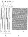
図26に、各色の多値データを2値の記録データへと変換する処理の一例を示す。ここでは、17値に量子化された各色の多値データを、4×4の升目からなる記録マトリックス(ドット配置パターンともいう)を一単位としたドット集中型の面積階調パターンに変換し、これを各画素に割り当てることで2値データを得る。 ここに示すドット配置パターンは、網点形状の画像を構成する目的で生成されたパターンとなっている。なお、図中の升目は、各ドットの形成位置を明らかにするため仮想的に示したものであり、この升目は1200dpiの解像度を有する。この1つの升目は、マスクパターンにおける1つのエリアに対応する。 FIG. 26 shows an example of processing for converting multi-value data of each color into binary print data. Here, the multi-value data of each color quantized to 17 values is converted into a dot-concentrated area gradation pattern with a recording matrix (also referred to as a dot arrangement pattern) composed of 4 × 4 cells as a unit, By assigning this to each pixel, binary data is obtained. The dot arrangement pattern shown here is a pattern generated for the purpose of forming a halftone image. Note that the squares in the figure are virtually shown to clarify the formation positions of the dots, and the squares have a resolution of 1200 dpi. This one cell corresponds to one area in the mask pattern.
なお、4×4の記録マトリックスにおいて、ドット集中型の面積階調法によって17階調を表すパターンの一例を図31に示す。図示のパターンは、表現すべき階調値が1階調増加する毎に、16個のマトリックスにおいて、より中央部に近い升目にドットを記録させるパターンとなっている。なお、図31では、16個のパターンしか示されておらず、一見すると16階調ですあるが、実はこれらのパターン以外に、ドットを全く形成しない階調値0のパターンが存在する。従って、図示される16個のパターンに階調値0のパターンを加えた計17個のパターンで17階調の表現が実現される。
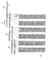
図27は、図26に示すドット集中型の面積階調パターンによって表される画像データを各記録走査に分割して記録する状態を示す図である。ここで、1画素に相当する単位形状は、4×4の升目からなる記録マトリックスによって構成され、全体の画像はこの単位形状を繰り返した構成となっている。なお、図中のX方向は、記録媒体上を記録ヘッドがインク滴を吐出しつつ走査する方向を示し、Y方向は記録ヘッドに設けられるノズル列の配列方向を示している。また、図中、升目内を黒く塗り潰した場所がインク滴を吐出するデータを示している。
図1に示すフルライン型のインクジェット記録装置または図3に示すシリアル型のインクジェット記録装置によって記録動作を行う場合には、図26に示す画像データを、この実施形態におけるマスクパターンを用いて、図17に示すように各走査毎に分配する。
FIG. 31 shows an example of a pattern representing 17 gradations by a dot concentration type area gradation method in a 4 × 4 recording matrix. The illustrated pattern is a pattern in which dots are recorded in a grid closer to the center in 16 matrices each time the gradation value to be expressed increases by one gradation. In FIG. 31, only 16 patterns are shown. At first glance, there are 16 gradations. Actually, however, there are patterns with
FIG. 27 is a diagram showing a state in which the image data represented by the dot concentration type area gradation pattern shown in FIG. Here, a unit shape corresponding to one pixel is constituted by a recording matrix composed of 4 × 4 cells, and the entire image has a configuration in which this unit shape is repeated. Note that the X direction in the figure indicates the direction in which the recording head scans the recording medium while ejecting ink droplets, and the Y direction indicates the arrangement direction of the nozzle rows provided in the recording head. Further, in the figure, the area where the inside of the grid is painted black indicates the data for ejecting ink droplets.
When the recording operation is performed by the full line type ink jet recording apparatus shown in FIG. 1 or the serial type ink jet recording apparatus shown in FIG. 3, the image data shown in FIG. 26 is displayed using the mask pattern in this embodiment. As shown in FIG. 17, distribution is performed for each scan.
この場合、記録ヘッドとしては、同色を吐出する第1〜第4のノズル列を有するものを用意し、各ノズル列によって順次記録動作を行う。すなわち、走査方向(記録媒体の搬送方向)において最上流側に位置する第1のノズル列によって図27Aに示したパターンデータの記録(第1走査)を行う。続いて第2のノズル列によって図27Bに示したパターンデータの記録(第2走査)を行う。続いて第3のノズル列によって図27Cに示したパターンデータの記録(第3走査)を行う。最後に第4のノズル列によって図27Dに示したパターンデータの記録(第4走査)を行う。以上によって一色分の画像が完成する。 In this case, a recording head having first to fourth nozzle arrays that discharge the same color is prepared, and the recording operation is sequentially performed by each nozzle array. That is, the pattern data recording (first scanning) shown in FIG. 27A is performed by the first nozzle row located on the most upstream side in the scanning direction (printing medium conveyance direction). Subsequently, pattern data recording (second scanning) shown in FIG. 27B is performed by the second nozzle row. Subsequently, the pattern data recording (third scan) shown in FIG. 27C is performed by the third nozzle row. Finally, pattern data recording (fourth scanning) shown in FIG. 27D is performed by the fourth nozzle row. Thus, an image for one color is completed.
また、図3に示すシリアル型のインクジェット記録装置により、図26に示す画像データを記録する場合には、記録ヘッドとして同色を記録するノズル列が2列(左列、右列)を配置されたものを使用し、これらのノズル列を用いて2回の主走査で画像を記録する。すなわち、第1回目の主走査では、左列により図27Aに示すパターンデータの記録(第1走査)を行うと共に、右列により図27Bに示すパターンデータの記録(第2走査)を行う。次いで、第2回目の主走査では、左列により図27Cに示すパターンデータの記録(第3走査)を行うと共に、右列により図27Cに示すパターンデータの記録(第4走査)を行う。以上により1色分の画像が完成する。 When the image data shown in FIG. 26 is recorded by the serial type ink jet recording apparatus shown in FIG. 3, two nozzle rows (left column and right column) for recording the same color are arranged as the recording head. A nozzle is used and an image is recorded by two main scans using these nozzle arrays. That is, in the first main scan, pattern data recording (first scan) shown in FIG. 27A is performed by the left column, and pattern data recording (second scan) shown in FIG. 27B is performed by the right column. Next, in the second main scan, pattern data recording (third scan) shown in FIG. 27C is performed in the left column, and pattern data recording (fourth scan) shown in FIG. 27C is performed in the right column. Thus, an image for one color is completed.
上記のような画像データの分割を行うマスクパターンMの一例を図28に示す。なお、図中の丸数字1,2,3,4は、図27第1走査、第2走査、第3走査、第4走査によって記録され得る位置をそれぞれ示している。このマスクパターンを用いて、上記のような分割記録を行うことにより、フルライン型、シリアル型のいずれのインクジェット記録装置においても、記録ヘッドと記録媒体との間に生じる乱流レベルを低減することが可能となる。これにより、インク滴の着弾位置を高精度に保つことが可能になり、高品質な画像を形成することが可能になる。
An example of the mask pattern M for dividing the image data as described above is shown in FIG. Note that the circled
このように、いずれの型のインクジェット記録装置においても、0.08mmの幅を有する単位形状分の領域(高記録率領域)毎に記録が行われる。しかも同時に記録される単位形状分の幅を有する領域の間には、記録の行われない3個の単位形状分の幅(0.24mm幅)を有する領域(低記録率領域)が存在する。このため、記録ヘッドと記録媒体との間に発生する乱流は大幅に低減され、インク滴の着弾位置は、高精度に保たれる。さらに、図28に示すマスクパターンMは、主走査方向において隣接する各単位形状が、副走査方向へと上下に2ドット分だけずらした配置となっており、高記録率領域と低記録率領域との境界が、連続的にノズルの配列方向に変化している(うねっている)。このため、一回の走査において、ノズルの使用頻度を均一化することができ、記録ヘッド全体の寿命を高めることができると共に、各領域間にスジむらが発生するの低減することができる。 Thus, in any type of ink jet recording apparatus, recording is performed for each region (high recording rate region) for a unit shape having a width of 0.08 mm. In addition, between the areas having a width corresponding to the unit shape that is simultaneously recorded, there is an area (low recording rate area) having a width (0.24 mm width) corresponding to three unit shapes that are not recorded. For this reason, the turbulent flow generated between the recording head and the recording medium is greatly reduced, and the landing position of the ink droplet is maintained with high accuracy. Further, the mask pattern M shown in FIG. 28 has an arrangement in which each unit shape adjacent in the main scanning direction is shifted up and down by 2 dots in the sub-scanning direction. The boundary between and continuously changes in the nozzle arrangement direction (swells). For this reason, the frequency of use of the nozzles can be made uniform in one scan, the life of the entire recording head can be increased, and the occurrence of uneven stripes between the regions can be reduced.
一方、図29は、図26に示すドット集中型の面積階調を行う画像データを、4回の記録走査に分割した他の例を示す図である。この場合にも、升目は1200dpiの解像度であり、画像の単位形状は4×4で構成されており、高記録率領域は4ノズル列分に相当する0.08mmとなっている。このため、乱流レベルを低減することができ、良好な品質の画像を記録することができる。 On the other hand, FIG. 29 is a diagram showing another example in which the image data for the dot concentration type area gradation shown in FIG. 26 is divided into four recording scans. Also in this case, the cell has a resolution of 1200 dpi, the unit shape of the image is 4 × 4, and the high recording rate area is 0.08 mm corresponding to 4 nozzle rows. For this reason, a turbulent flow level can be reduced and a good quality image can be recorded.
また、本発明は、ほぼ同一の色相を有し、かつ濃度の異なる複数種類のインクを吐出する記録ヘッドを用いるインクジェット記録装置や、異なるインク量のインク滴を吐出するノズルを配列した記録ヘッドを用いるインクジェット記録装置などにも適用可能である。いずれの場合にも、使用するノズル列の数、インクの種類、記録媒体の種類、記録速度、および記録するインク滴の量などに応じて、ノズル列に設定すべき高記録率領域と低記録率領域の幅を設定すれば良い。 The present invention also provides an inkjet recording apparatus using a recording head that discharges a plurality of types of ink having substantially the same hue and different densities, and a recording head in which nozzles that discharge ink droplets of different ink amounts are arranged. The present invention can also be applied to an inkjet recording apparatus to be used. In any case, the high recording rate region and low recording to be set in the nozzle row according to the number of nozzle rows to be used, the type of ink, the type of recording medium, the recording speed, the amount of ink droplets to be recorded, etc. The width of the rate area may be set.
一例として、6plを吐出するノズル(大ノズル)と、1plを吐出するノズル(小ノズル)とを交互に配列すると共に、その配列密度を1200dpiとした記録ヘッドを用いて記録動作を行う場合の模式図を図16に示す。ここでは、2個の大ノズルと2個の小ノズルの合計4個のノズルを高記録率領域Hnとして設定している。また、低記録率領域Lnも高記録率領域Hnと同様に、合計4個の大、小のノズルによって設定しており、これによって合計2回の走査で画像が完成される。
この場合にも、高記録率領域Hnが0.08mmとなるため、低い乱流レベルでの記録が可能となり、良好な画像を記録することができる。
As an example, a model in which a recording operation is performed using a recording head in which nozzles that discharge 6 pl (large nozzles) and nozzles that discharge 1 pl (small nozzles) are alternately arranged and the arrangement density is 1200 dpi. The figure is shown in FIG. Here, a total of four nozzles of two large nozzles and two small nozzles are set as the high recording rate area Hn. Similarly to the high recording rate region Hn, the low recording rate region Ln is set by a total of four large and small nozzles, and thus an image is completed by a total of two scans.
Also in this case, since the high recording rate region Hn is 0.08 mm, recording at a low turbulence level is possible, and a good image can be recorded.
ところで、上記のような高密度なノズル列を比較的簡易にかつ低コストで実現できるインクジェット記録方式としては、例えば、熱エネルギーを利用して飛翔的液滴を形成し、記録を行う記録ヘッドを用いたインクジェット記録方式がある。しかし、本発明は特にこれに限定されるものではない。 By the way, as an ink jet recording method that can realize the above-described high-density nozzle row relatively easily and at low cost, for example, a recording head that forms recording by using thermal energy and performs recording is used. There is an ink jet recording method used. However, the present invention is not particularly limited to this.
次に、以下の実施例により本発明をより具体的に説明する。
〈実施例1〉
図1に示すフルライン型のインクジェット記録装置において、図2に示すインクジェット記録ヘッドを用い、記録動作を行った。この際、記録ヘッドから吐出されるインクとしては、市販のBJF900(本願出願人製)用のインクBCI6ブラックを用いた。なお、各インク滴は、2.5±0.5plで吐出するようにした。
また、記録媒体としてはインクジェット専用フォト光沢紙(プロフォトペーパー、PR101:本願出願人製)を用意した。
Next, the present invention will be described more specifically with reference to the following examples.
<Example 1>
In the full-line type ink jet recording apparatus shown in FIG. 1, a recording operation was performed using the ink jet recording head shown in FIG. At this time, as the ink ejected from the recording head, commercially available ink BCI6 black for BJF900 (manufactured by the present applicant) was used. Each ink droplet was ejected at 2.5 ± 0.5 pl.
In addition, as a recording medium, photo glossy paper dedicated to inkjet (Pro Photo Paper, PR101: manufactured by the present applicant) was prepared.
図17は、この実施例で用いる記録ヘッドのノズル列およびマスクパターンMを模式的に示す図である。なお、図17に示す記録ヘッドは、実際には図2に示す構成を有するものであるが、ここでは、便宜上、図2に示す千鳥状に配列されたノズルを一列にみなして記載してある。
図2のノズル列(中ノズル列)171,175からなる上流側の第1ノズル列17Aは、図17Bにおいて丸数字1と丸数字5とで示される位置の記録データを記録する。なお、図17Bは間引き処理を行うマスクパターンMを表している。
FIG. 17 is a diagram schematically showing a nozzle array and a mask pattern M of the recording head used in this embodiment. The recording head shown in FIG. 17 actually has the configuration shown in FIG. 2, but here, for convenience, the nozzles arranged in a staggered pattern shown in FIG. .
The upstream
続いて、図2の172,176からなる第2ノズル列17Bは、図17の丸数字2と丸数字6で示す位置のデータを記録する。同様に第3ノズル列171Cは丸数字3と丸数字7で示す位置のデータを、第4ノズル列171Dは、丸数字4と丸数字8に示す位置のデータを記録する。
Subsequently, the
図17Aにおいて、ノズル列171の中で二重丸を記したノズルからなる領域は、高記録率領域である。この高記録領域は、1200dpiの密度で4ノズル分の領域幅、すなわち0.08mmの幅を有する短冊状の領域となっている。また、単に丸のみを記したノズルは、低記録比率領域である。なお、ここでは低記録領域においてインク吐出を行っていない。
In FIG. 17A, a region composed of nozzles with double circles in the
また、ノズル列171A,171Dにおいて、各々を構成する2本の中ノズル列171と175、および174と178は、いずれも端部をオーバーラップさせた状態で連結してあり、その連結部分に相当するノズルは各ノズル列とも高記録領域にしている。これにより、つなぎ部の画像劣化を軽減することができる。
Further, in the nozzle rows 171A and 171D, the two
記録動作における記録条件として、吐出の周波数を30kHzとし、記録ヘッドと記録媒体の相対移動速度を25inch/sとして画像を形成した。その結果、乱流の影響とみられる画像の劣化(濃度むら)は低減され、高品質な画像を得ることができた。 As recording conditions in the recording operation, an image was formed with an ejection frequency of 30 kHz and a relative movement speed of the recording head and the recording medium of 25 inches / s. As a result, image degradation (density unevenness) that appears to be the effect of turbulence was reduced, and a high-quality image could be obtained.
〈比較例1〉
上記実施例1と同様のインクジェット記録装置を用いて、図18Aに示すような、ノズル列に対する画像データを均一に間引くマスクパターンM(図18B参照)によって分割記録を行った。この場合、乱流による影響とみられる濃度むらが発生し、品位の低い画像しか得られなかった。
<Comparative example 1>
Using the same ink jet recording apparatus as that used in Example 1, divided recording was performed using a mask pattern M (see FIG. 18B) that uniformly thins out image data for the nozzle rows as shown in FIG. 18A. In this case, density unevenness that appears to be an effect of turbulent flow occurred, and only low-quality images were obtained.
〈実施例2〉
上記実施例1と同様のインクジェット記録装置を用い、図17に示すように高記録率領域と低記録率領域とを設定した分割記録を行った。この際、高記録比率領域の幅は、1200dpiの密度のノズル列で16ノズル分(0.32mm)の幅に拡大した。このようにして記録を行った結果、乱流による影響とみられる濃度むらは発生せず高品位な画像が得られた。
<Example 2>
Using the same ink jet recording apparatus as in Example 1, divided recording was performed in which a high recording rate region and a low recording rate region were set as shown in FIG. At this time, the width of the high recording ratio area was increased to a width of 16 nozzles (0.32 mm) with a nozzle row having a density of 1200 dpi. As a result of recording in this way, a high-quality image was obtained without causing density unevenness that was considered to be caused by turbulence.
〈実施例3〉
上記実施例1と同様のインクジェット記録装置を用い、図17に示すように高記録率領域と低記録率領域とを設定した分割記録において、高記録比率領域の幅をさらに広げ、1200dpiの密度のノズル列で64ノズル分(1.2mm)の幅として記録を行った。この場合も、気流による影響とみられる濃度むらは低減され、高品位な画像が得られた。しかしながら所定幅ピッチの筋むらが僅かながら視認された。
<Example 3>
In the divided recording in which the high recording rate region and the low recording rate region are set as shown in FIG. 17 using the same ink jet recording apparatus as in Example 1, the width of the high recording rate region is further widened and the density is 1200 dpi. Recording was performed with a nozzle row having a width of 64 nozzles (1.2 mm). Also in this case, the density unevenness considered to be influenced by the airflow was reduced, and a high-quality image was obtained. However, a slight amount of stripe irregularity with a predetermined width pitch was visually recognized.
〈比較例2〉
上記実施例1と同様の記録装置を用いて、図17に示すように高記録率領域と低記録率領域とを設定した分割記録において、高記録比率領域の幅をさらに広げ、1200dpiの密度のノズル列で128ノズル分(2.4mm)の幅とした。この場合には、所定幅ピッチのスジが顕著に現れるようになり、高品位な画像とは言い難い状態となった。これは気流による影響とみられる濃度むらが所定幅内に発生したことに起因するものと推察される。
<Comparative example 2>
In the divided recording in which the high recording ratio area and the low recording ratio area are set as shown in FIG. 17 using the same recording apparatus as in the first embodiment, the width of the high recording ratio area is further expanded and the density of 1200 dpi is obtained. The width of the nozzle row was 128 nozzles (2.4 mm). In this case, streaks with a predetermined width pitch appear remarkably, and it is difficult to say that the image is a high-quality image. This is presumably due to the occurrence of density unevenness that appears to be influenced by the airflow within a predetermined width.
〈実施例4〉
上記実施例1と同様の記録装置を用いると共に、図19Bに示すように主走査方向に延びる短冊状の高記録比率領域が記録媒体の搬送方向にうねるようなマスクパターンMを用いて画像データを間引き、図19Aに示すラインヘッド17によって分割記録を行った。その結果、乱流による影響とみられる濃度むらは発生せず高品位な画像が得られた。
<Example 4>
While using the same recording apparatus as in the first embodiment, image data is obtained using a mask pattern M in which a strip-like high recording ratio area extending in the main scanning direction undulates in the conveyance direction of the recording medium as shown in FIG. 19B. Thinning and division recording were performed by the
〈実施例5〉
インクジェット記録ヘッドとして、図4に示すような平均2.5plを吐出するノズルが768個1200dpiで配置されたノズル列を有する記録ヘッド22を用意し、これを図3に示すシリアル型のインクジェット記録装置に装着して記録を行った。各インク滴は、2.5±0.5plで吐出するようにした。インクとしては、市販のBJF900(本願出願人製)用のインクBCI6ブラックを用いた。
<Example 5>
As the ink jet recording head, a
記録媒体としてはインクジェット専用フォト光沢紙(プロフォトペーパー、PR101:本願出願人製)を使用した。 As a recording medium, photo glossy paper dedicated to inkjet (Pro Photo Paper, PR101: manufactured by the present applicant) was used.
ここで、図20に同一の記録領域に対して2回の走査で画像を完成させる分割記録の様子を示した。なお、図20に示す記録ヘッドは、実際には図4に示す構成を有するものであるが、ここでは、便宜上、図4に示す千鳥状に配列されたノズルを一列にみなして記載してある。
この記録動作においては、図20の丸数字1で示す位置のデータを第1走査で記録する。続いて図20の丸数字2で示す位置のデータを第2走査で記録する。続いて第3走査において、図20の丸数字3で示す位置を記録し、以上の動作を繰り返すことで画像を完成させた。ここでノズル列のマスに二重丸を付したものは高記録率領域を示し、1200dpiで12ノズル分の幅(0.25mm)に設定されている。また、低記録率領域も同様である。記録条件は、吐出の周波数を30kHzとし、記録ヘッドと記録媒体の相対移動速度を25inch/sとした。
このような記録条件の下に記録動作を行った結果、乱流による影響とみられる濃度むらは発生せず高品位な画像が得られた。
Here, FIG. 20 shows a state of divided recording in which an image is completed by two scans in the same recording area. The recording head shown in FIG. 20 actually has the configuration shown in FIG. 4, but here, for convenience, the nozzles arranged in a staggered pattern shown in FIG. .
In this recording operation, the data at the position indicated by the circled numeral 1 in FIG. 20 is recorded in the first scan. Subsequently, data at a position indicated by a circled number 2 in FIG. 20 is recorded by the second scan. Subsequently, in the third scan, the position indicated by the circled numeral 3 in FIG. 20 was recorded, and the above operation was repeated to complete the image. Here, a double circle added to the square of the nozzle row indicates a high recording rate area, and is set to a width of 12 nozzles (0.25 mm) at 1200 dpi. The same applies to the low recording rate area. The recording conditions were an ejection frequency of 30 kHz and a relative movement speed of the recording head and the recording medium of 25 inches / s.
As a result of performing the recording operation under such recording conditions, high-quality images were obtained without causing density unevenness that was considered to be caused by turbulence.
〈比較例3〉
上記実施例5と同様のインクジェット記録装置を用いて、図21に示す間引きマスクパターンにより記録ヘッド22のノズル列に記録データを均一に分配し、分割記録を行った。その結果、乱流による影響とみられる濃度むらが発生し、品位の低い画像しか得られなかった。
<Comparative Example 3>
Using the same ink jet recording apparatus as in Example 5 above, the recording data was uniformly distributed to the nozzle rows of the
〈実施例6〉
上記実施例4と同様のインクジェット記録装置を用いて、図22に示すように高記録率領域と低記録率領域の境界において、記録比率に勾配を持たせた間引きマスクパターンを用いて画像データを間引き、記録ヘッド22によって分割記録を行った。その結果、乱流による影響とみられる濃度むらは発生せず、高品位な画像が得られた。
<Example 6>
Using the same ink jet recording apparatus as in Example 4, the image data is obtained using a thinning mask pattern having a gradient in the recording ratio at the boundary between the high recording rate region and the low recording rate region as shown in FIG. Thinning and division recording were performed by the
〈実施例7〉
上記実施例4と同様のインクジェット記録装置を用いて、図23に示すように高記録率領域を階段状にうねらせた間引きマスクパターンMを用いて画像データを間引き、記録ヘッド22によって分割記録を行った。その結果、乱流による影響とみられる濃度むらは発生せず、高品位な画像が得られた。
<Example 7>
Using the same ink jet recording apparatus as in Example 4 above, image data is thinned out using a thinning mask pattern M in which a high recording rate region is undulated as shown in FIG. went. As a result, the density unevenness considered to be influenced by turbulent flow did not occur, and a high-quality image was obtained.
〈実施例8〉
上記実施例4と同様のインクジェット記録装置を用いて、図24に示すように、600dpiの密度でノズルを配列してなるノズル列内に、記録率90%の高記録率領域と記録率10%の低記録率領域とを設定した。さらに、高記録率領域の幅を1.2mmとして分割記録を行った。その結果、乱流による影響にとみられる画像の劣化は低減され、高品質な画像が得られた。
<Example 8>
Using the same ink jet recording apparatus as in Example 4, as shown in FIG. 24, a high recording rate region with a recording rate of 90% and a recording rate of 10% are arranged in a nozzle array in which nozzles are arranged at a density of 600 dpi. And a low recording rate area. Further, divided recording was performed with the width of the high recording rate area being 1.2 mm. As a result, the degradation of the image, which appears to be affected by turbulence, was reduced, and a high-quality image was obtained.
〈実施例9〉
上記実施例4と同様のインクジェット記録装置を用いて、図25に示すように高記録比率領域の幅を0.08mmに取り、4回の走査に分配する間引きマスクパターンMを用いて画像データを間引き、記録ヘッド22によって分割記録を行った。その結果、乱流による影響とみられる濃度むらは発生せず高品位な画像が得られた。
<Example 9>
Using the same ink jet recording apparatus as in Example 4 above, the width of the high recording ratio area is set to 0.08 mm as shown in FIG. 25, and the image data is acquired using the thinning mask pattern M distributed to four scans. Thinning and division recording were performed by the
〈実施例10〉
実施例4のインクジェット記録装置を用いて、図31に示す面積階調を施した2値画像データを図27に示すように展開し、図26に示す第1走査から第4走査の画像データに従って、4パスのマルチパス記録を行った。この場合、画像の単位形状である記録マトリックスは、4×4の升目によって構成し、各升目は1200×1200dpiの密度に設定した。このため、画像の記録は、ノズル列方向において0.08mm単位で繰り返され、高記録率領域は0.08mm幅を有する短冊状に形成された。その結果、記録された画像には乱流による影響はみられず、良好な品質を得ることができた。
<Example 10>
Using the inkjet recording apparatus of Example 4, the binary image data having the area gradation shown in FIG. 31 is developed as shown in FIG. 27, and according to the image data of the first scan to the fourth scan shown in FIG. 4-pass multipass recording was performed. In this case, the recording matrix, which is the unit shape of the image, is composed of 4 × 4 cells, and each cell is set to a density of 1200 × 1200 dpi. For this reason, image recording was repeated in units of 0.08 mm in the nozzle row direction, and the high recording rate area was formed in a strip shape having a width of 0.08 mm. As a result, the recorded image was not affected by the turbulent flow and good quality could be obtained.
〈実施例11〉
実施例4と同様のインクジェット記録装置を用いて、図31に示す面積階調を施した2値画像データを図27に示すように展開し、図29に示す第1走査から第4走査の画像データに従って、4パスのマルチパス記録を行った。この場合においても、画像の単位形状である記録マトリックスは、4×4の升目によって構成し、各升目は1200×1200dpiの密度に設定した。これにより、画像の記録は、ノズル列方向において0.08mm単位で繰り返され、高記録率領域は0.08mm幅を有する短冊状に形成された。従って、この場合にも、記録された画像には乱流による影響はみられず、良好な品質を得ることができた。
<Example 11>
Using the same ink jet recording apparatus as in Example 4, the binary image data having the area gradation shown in FIG. 31 is developed as shown in FIG. 27, and the first to fourth scan images shown in FIG. 29 are developed. According to the data, 4-pass multipass recording was performed. Also in this case, the recording matrix, which is the unit shape of the image, is composed of 4 × 4 cells, and each cell is set to a density of 1200 × 1200 dpi. Thereby, the image recording was repeated in units of 0.08 mm in the nozzle row direction, and the high recording rate area was formed in a strip shape having a width of 0.08 mm. Therefore, even in this case, the recorded image was not affected by the turbulent flow, and good quality could be obtained.
〈実施例12〉
実施例8と同様のインクジェット記録装置を用いて、図30に示すように4×4の升目からなる記録マトリックスを単位形状とする画像データに従って記録を行った。この場合、高記録率領域の間に、前記単位形状の整数倍となる低記録率領域を含むように間引きマスクパターンMを設定し、2パスのマルチパス記録を行った。各パスにおいては図28の高記録比領域と低記録率領域の位置に応じて記録を行った。記録マトリックスが4×4の升目で構成し、各升目は1200×1200dpiの密度に設定した。これにより、画像の記録は、ノズル列方向で0.08mm単位で繰り返され、高記録率領域は0.32mm幅の短冊状に設定される。その結果、乱流による影響は低減され、良好な画質を得ることができた。
<Example 12>
Using the same ink jet recording apparatus as in Example 8, recording was performed according to image data having a recording matrix composed of 4 × 4 squares as a unit shape as shown in FIG. In this case, the thinning mask pattern M was set so as to include a low recording rate area that is an integral multiple of the unit shape between the high recording rate areas, and two-pass multipass recording was performed. In each pass, recording was performed in accordance with the positions of the high recording ratio area and the low recording ratio area in FIG. The recording matrix was composed of 4 × 4 cells, and each cell was set to a density of 1200 × 1200 dpi. Thereby, the image recording is repeated in units of 0.08 mm in the nozzle row direction, and the high recording rate area is set to a strip shape having a width of 0.32 mm. As a result, the influence of turbulent flow was reduced, and good image quality could be obtained.
以上のように、本発明は、比較的短いノズル列を並設した記録ヘッドを用いるシリアル型の記録装置でマルチパス記録などの分割記録を行う場合、また長尺なノズル列を複数並設してなるフルライン型の記録装置によって記録を行う場合に有効である。すなわち、いずれの記録方式においても、記録ヘッドと記録媒体との間に発生する乱流によるインク滴の着弾位置の変動を、著しく改善することができ、高速で高画質な記録物を得ることができる。また、本発明はドット集中型面積階調法の記録に対し適切に利用でき、階調再現性を維持しつつ高速記録が可能になる。 As described above, according to the present invention, when performing division recording such as multi-pass printing in a serial type recording apparatus using a recording head in which relatively short nozzle rows are arranged, a plurality of long nozzle rows are arranged in parallel. This is effective when recording is performed by a full-line type recording apparatus. That is, in any recording method, the fluctuation of the landing position of the ink droplet due to the turbulent flow generated between the recording head and the recording medium can be remarkably improved, and a high-quality recorded product can be obtained at high speed. it can. In addition, the present invention can be appropriately used for dot-concentrated area gradation method recording, and high-speed recording is possible while maintaining gradation reproducibility.
本発明は、紙や布、革、不織布、OHP用紙等、さらには金属などの記録媒体を用いる機器すべてに適用可能である。具体的な適用機器としては、プリンタ、複写機、ファクシミリ等の事務機器や工業用生産機器等を挙げることができる。
また、クラスター型あるいはドット集中型と呼ばれ、広く「網点階調法」として知られている面積階調法を、インクジェット方式によるプリンタで実現する場合に、本発明は適している。面積階調法を実現するプリンタとしては、印刷業で広く用いられているプルーフ用途のプリンターがある。
本出願は、2004年12月13日に出願された特願2004−360514に基づいて優先権を主張し、前記日本国特許出願は、この参照によって本明細書に含まれる。
The present invention is applicable to all devices using recording media such as paper, cloth, leather, non-woven fabric, OHP paper, and metal. Specific examples of applicable equipment include office equipment such as printers, copiers, and facsimile machines, and industrial production equipment.
The present invention is suitable when an area gradation method called a cluster type or a dot concentration type and widely known as a “halftone gradation method” is realized by an ink jet printer. Printers that realize the area gradation method include proof-use printers that are widely used in the printing industry.
This application claims priority based on Japanese Patent Application No. 2004-360514 filed on Dec. 13, 2004, which is hereby incorporated by reference.
1 フルライン型インクジェット記録装置
2 シリアル型インクジェット記録装置
17 ラインヘッド
17A〜17D ノズル列
22 記録ヘッド
22A〜22D ノズル列
71 データ入力部
73 CPU
75 RAM
74 記憶媒体
76 画像処理部
77 画像記録部
110 マスクパターン
120 マスクパターン
130 マスクパターン
140 マスクパターン
150 マスクパターン
M マスクパターン
n ノズル
P 記録媒体
DESCRIPTION OF
75 RAM
74
Claims (9)
前記記録媒体の同一の記録領域に対して前記記録ヘッドを相対的に複数回走査させる走査手段と、
前記同一の記録領域に記録すべき画像に対応する多値の画像データを、2値の画像データに変換する変換手段と、
前記同一の記録領域に対する複数回の走査それぞれに対応する異なるマスクパターンを用い、前記同一の記録領域に対応する2値の画像データを間引く間引き手段と、
前記複数回の走査それぞれにおいて前記間引き手段により間引かれた2値の画像データに基づいて前記同一の記録領域に間引き画像を記録することにより、前記同一の記録領域に記録すべき画像を完成させる記録制御手段とを備え、
前記異なるマスクパターンの夫々は、前記2値の画像データを相対的に高い間引き率で間引く第1領域と相対的に低い間引き率で間引く第2領域とが前記ノズルの配列方向に配列されるとともに、前記第1領域の前記ノズル列方向の幅は前記第2領域の前記ノズル配列方向の幅よりも大きいことを特徴とするインクジェット記録装置。 An inkjet recording apparatus that records an image on the recording medium by ejecting ink droplets from the nozzle while scanning a recording head in which a plurality of nozzles are arranged relative to the recording medium,
Scanning means for scanning the recording head relative to the same recording area of the recording medium a plurality of times;
Conversion means for converting multivalued image data corresponding to an image to be recorded in the same recording area into binary image data;
And thinning means for thinning the binary image data using a different mask patterns corresponding to the respective scanning multiple times, corresponding to the same recording area against the same recording area,
An image to be recorded in the same recording area is completed by recording a thinned image in the same recording area based on the binary image data thinned out by the thinning means in each of the plurality of scans. Recording control means,
In each of the different mask patterns, a first region where the binary image data is thinned out at a relatively high thinning rate and a second region where the binary image data is thinned out at a relatively low thinning rate are arranged in the nozzle arrangement direction. An inkjet recording apparatus, wherein a width of the first region in the nozzle array direction is larger than a width of the second region in the nozzle array direction .
前記記録媒体の同一の記録領域に対して前記記録ヘッドを相対的に複数回走査させる走査手段と、
前記同一の記録領域に記録すべき画像を構成する各画素に対応する多値の画像データを、2値の画像データに変換する変換手段と、
前記同一の記録領域に対する複数回の走査それぞれに対応する異なるマスクパターンを用い、前記同一の記録領域に対応する2値の画像データを間引く間引き手段と、
前記複数回の走査それぞれにおいて前記間引き手段により間引かれた2値の画像データに基づいて前記同一の記録領域に間引き画像を記録することにより、前記同一の記録領域に記録すべき画像を完成させる記録制御手段とを備え、
前記異なるマスクパターンの夫々は、前記2値の画像データを相対的に高い間引き率で間引く第1領域と相対的に低い間引き率で間引く第2領域とが、前記ノズルの配列方向に、前記画素の幅の整数倍の幅の単位で、繰り返し配列されてなることを特徴とするインクジェット記録装置。 An inkjet recording apparatus that records an image on the recording medium by ejecting ink droplets from the nozzle while scanning a recording head in which a plurality of nozzles are arranged relative to the recording medium,
Scanning means for scanning the recording head relative to the same recording area of the recording medium a plurality of times;
Conversion means for converting multivalued image data corresponding to each pixel constituting an image to be recorded in the same recording area into binary image data;
Thinning means for thinning out binary image data corresponding to the same recording area using different mask patterns corresponding to each of a plurality of scans for the same recording area;
An image to be recorded in the same recording area is completed by recording a thinned image in the same recording area based on the binary image data thinned out by the thinning means in each of the plurality of scans. Recording control means,
Each of the different mask patterns includes a first region that thins out the binary image data at a relatively high thinning rate and a second region that thins out at a relatively low thinning rate in the nozzle arrangement direction. An ink jet recording apparatus, wherein the ink jet recording apparatus is repeatedly arranged in a unit of a width that is an integral multiple of the width of.
前記記録媒体の同一の記録領域に対して前記記録ヘッドを相対的に複数回走査させる走査工程と、
前記同一の記録領域に記録すべき画像に対応する多値の画像データを、2値の画像データに変換する工程と、
前記同一の記録領域に対する複数回の走査それぞれに対応する異なるマスクパターンを用い、前記同一の記録領域に対応する2値の画像データを間引く工程と、
前記複数回の走査それぞれにおいて間引かれた2値の画像データに基づいて前記同一の記録領域に間引き画像を記録することにより、前記同一の記録領域に記録すべき画像を完成させる工程とを備え、
前記異なるマスクパターンの夫々は、前記2値の画像データを相対的に高い間引き率で間引く第1領域と相対的に低い間引き率で間引く第2領域とが前記ノズルの配列方向に配列されるとともに、前記第1領域の前記ノズル列方向の幅は前記第2領域の前記ノズル配列方向の幅よりも大きいことを特徴とするインクジェット記録方法。 An inkjet recording method for recording an image on the recording medium by ejecting ink droplets from the nozzle while scanning a recording head in which a plurality of nozzles are arranged relative to the recording medium,
A scanning step of relatively scanning the recording head a plurality of times with respect to the same recording area of the recording medium;
Converting multi-value image data corresponding to an image to be recorded in the same recording area into binary image data;
Using different mask patterns corresponding to the respective scanning multiple times against the same recording area, and the more thinning rather Engineering image data of the corresponding binary to the same recording area,
By recording an image thinning the same recording area on the basis of the binary image data drawn between Te said plural scans each odor, as engineering of Ru to complete an image to be recorded on the same recording area And
In each of the different mask patterns, a first region where the binary image data is thinned out at a relatively high thinning rate and a second region where the binary image data is thinned out at a relatively low thinning rate are arranged in the nozzle arrangement direction. An ink jet recording method, wherein a width of the first region in the nozzle array direction is larger than a width of the second region in the nozzle array direction .
前記記録媒体の同一の記録領域に対して前記記録ヘッドを相対的に複数回走査させる工程と、
前記同一の記録領域に記録すべき画像を構成する各画素に対応する多値の画像データを、2値の画像データに変換する工程と、
前記同一の記録領域に対する複数回の走査それぞれに対応する異なるマスクパターンを用いて、前記同一の記録領域に対応する2値の画像データを間引く工程と、
前記複数回の走査それぞれにおいて前記間引かれた2値の画像データに基づいて前記同一の記録領域に間引き画像を記録することにより、前記同一の記録領域に記録すべき画像を完成させる工程とを備え、
前記異なるマスクパターンの夫々は、前記2値の画像データの記録を許容するエリアと前記2値の画像データの記録を許容しないエリアとが配列されてなり、且つ前記ノズルの配列方向に、前記画素の幅の整数倍の幅の単位で、前記記録許容エリアが占める割合が相対的に高い部分と相対的に低い部分とが繰り返し配列されてなることを特徴とするインクジェット記録方法。 An inkjet recording method for forming an image on the recording medium by ejecting ink droplets from the nozzle while scanning a recording head having a plurality of nozzles arranged relative to the recording medium,
Scanning the recording head relative to the same recording area of the recording medium a plurality of times;
Converting multi-value image data corresponding to each pixel constituting an image to be recorded in the same recording area into binary image data;
Thinning out binary image data corresponding to the same recording area using different mask patterns corresponding to each of a plurality of scans for the same recording area;
Recording a thinned image in the same recording area based on the thinned binary image data in each of the plurality of scans, thereby completing an image to be recorded in the same recording area; Prepared,
Each of the different mask patterns includes an area in which recording of the binary image data is allowed and an area in which recording of the binary image data is not allowed, and the pixels are arranged in the nozzle arrangement direction. An ink jet recording method, wherein a portion having a relatively high ratio and a portion having a relatively low ratio occupied by the permissible recording area are repetitively arranged in a unit of a width that is an integral multiple of the width.
Priority Applications (1)
| Application Number | Priority Date | Filing Date | Title |
|---|---|---|---|
| JP2005359510A JP4717620B2 (en) | 2004-12-13 | 2005-12-13 | Inkjet recording method and inkjet recording apparatus |
Applications Claiming Priority (3)
| Application Number | Priority Date | Filing Date | Title |
|---|---|---|---|
| JP2004360514 | 2004-12-13 | ||
| JP2004360514 | 2004-12-13 | ||
| JP2005359510A JP4717620B2 (en) | 2004-12-13 | 2005-12-13 | Inkjet recording method and inkjet recording apparatus |
Publications (3)
| Publication Number | Publication Date |
|---|---|
| JP2006192892A JP2006192892A (en) | 2006-07-27 |
| JP2006192892A5 JP2006192892A5 (en) | 2010-02-25 |
| JP4717620B2 true JP4717620B2 (en) | 2011-07-06 |
Family
ID=36799315
Family Applications (1)
| Application Number | Title | Priority Date | Filing Date |
|---|---|---|---|
| JP2005359510A Expired - Fee Related JP4717620B2 (en) | 2004-12-13 | 2005-12-13 | Inkjet recording method and inkjet recording apparatus |
Country Status (1)
| Country | Link |
|---|---|
| JP (1) | JP4717620B2 (en) |
Families Citing this family (18)
| Publication number | Priority date | Publication date | Assignee | Title |
|---|---|---|---|---|
| JP2008094044A (en) | 2006-10-16 | 2008-04-24 | Seiko Epson Corp | Head unit, droplet discharge device, discharge method of liquid matter, manufacturing method of color filter, manufacturing method of organic el element and manufacturing method of wiring board |
| JP5277604B2 (en) * | 2007-10-15 | 2013-08-28 | セイコーエプソン株式会社 | Control of liquid jet unevenness |
| JP2011005703A (en) | 2009-06-24 | 2011-01-13 | Canon Inc | Ink jet recording apparatus and ink jet recording method |
| JP5787474B2 (en) * | 2009-10-08 | 2015-09-30 | キヤノン株式会社 | Image processing apparatus, image processing method, and program |
| JP5665386B2 (en) | 2010-06-24 | 2015-02-04 | キヤノン株式会社 | Image processing apparatus and image processing method |
| JP5936499B2 (en) * | 2012-09-20 | 2016-06-22 | 理想科学工業株式会社 | Image forming apparatus |
| JP5936501B2 (en) * | 2012-09-21 | 2016-06-22 | 理想科学工業株式会社 | Image forming apparatus |
| JP6212902B2 (en) | 2013-03-28 | 2017-10-18 | セイコーエプソン株式会社 | Printing apparatus and printing method |
| JP5668792B2 (en) * | 2013-06-19 | 2015-02-12 | セイコーエプソン株式会社 | Printing apparatus, printing method, computer program, and recording medium |
| JP2014058172A (en) * | 2014-01-07 | 2014-04-03 | Seiko Epson Corp | Liquid ejecting apparatus |
| JP6434817B2 (en) * | 2014-03-07 | 2018-12-05 | 株式会社ミマキエンジニアリング | Printing apparatus and printing method |
| JP6317141B2 (en) * | 2014-03-07 | 2018-04-25 | 株式会社ミマキエンジニアリング | Printing apparatus and printing method |
| JP6208052B2 (en) * | 2014-03-10 | 2017-10-04 | 株式会社Screenホールディングス | Inkjet printer and image recording method |
| JP6520265B2 (en) * | 2015-03-20 | 2019-05-29 | セイコーエプソン株式会社 | Liquid injection device |
| US10414171B2 (en) * | 2016-10-25 | 2019-09-17 | Memjet Technology Limited | Method of printing foreground and background images with overlapping printhead segments |
| JP6977329B2 (en) * | 2017-06-22 | 2021-12-08 | コニカミノルタ株式会社 | Inkjet recording device and image recording method |
| JP7062988B2 (en) * | 2018-02-09 | 2022-05-09 | セイコーエプソン株式会社 | Printing equipment, printing method |
| WO2022049994A1 (en) * | 2020-09-03 | 2022-03-10 | コニカミノルタ株式会社 | Method of pattern formation |
Citations (4)
| Publication number | Priority date | Publication date | Assignee | Title |
|---|---|---|---|---|
| JPH05169681A (en) * | 1991-12-20 | 1993-07-09 | Canon Inc | Ink jet recorder |
| JPH06336016A (en) * | 1993-05-27 | 1994-12-06 | Canon Inc | Ink jet recording method and recorder |
| JP2002096455A (en) * | 1999-08-24 | 2002-04-02 | Canon Inc | Device for ink jet recording, method for ink jet recording and method for controlling recording operation of device for ink jet recording |
| JP2004243574A (en) * | 2003-02-12 | 2004-09-02 | Canon Inc | Ink jet recording head and ink jet recording method |
-
2005
- 2005-12-13 JP JP2005359510A patent/JP4717620B2/en not_active Expired - Fee Related
Patent Citations (4)
| Publication number | Priority date | Publication date | Assignee | Title |
|---|---|---|---|---|
| JPH05169681A (en) * | 1991-12-20 | 1993-07-09 | Canon Inc | Ink jet recorder |
| JPH06336016A (en) * | 1993-05-27 | 1994-12-06 | Canon Inc | Ink jet recording method and recorder |
| JP2002096455A (en) * | 1999-08-24 | 2002-04-02 | Canon Inc | Device for ink jet recording, method for ink jet recording and method for controlling recording operation of device for ink jet recording |
| JP2004243574A (en) * | 2003-02-12 | 2004-09-02 | Canon Inc | Ink jet recording head and ink jet recording method |
Also Published As
| Publication number | Publication date |
|---|---|
| JP2006192892A (en) | 2006-07-27 |
Similar Documents
| Publication | Publication Date | Title |
|---|---|---|
| JP4717620B2 (en) | Inkjet recording method and inkjet recording apparatus | |
| WO2006064820A1 (en) | Ink jet recording method and ink jet recording device | |
| JP4164305B2 (en) | Inkjet recording method and inkjet recording apparatus | |
| JP4227627B2 (en) | Inkjet recording apparatus and image processing method | |
| JP5038076B2 (en) | Inkjet recording apparatus and inkjet recording method | |
| JP2006341406A (en) | Inkjet recording system | |
| JP2004276473A (en) | Recorder and method of recording | |
| JP5025327B2 (en) | Ink jet recording apparatus and recording method | |
| JP2011126173A (en) | Inkjet recording system, inkjet recording method and program | |
| JP4343867B2 (en) | Inkjet recording device | |
| JP2011005703A (en) | Ink jet recording apparatus and ink jet recording method | |
| JP4979485B2 (en) | Inkjet recording device | |
| JPH07232434A (en) | Method and device for recording | |
| JP2010143013A (en) | Inkjet print head, printing method and device using the same | |
| JP2006159697A (en) | Recording method and recorder | |
| JP2006159698A (en) | Recording method and recorder | |
| JP2006168073A (en) | Inkjet recording system | |
| JPH0811298A (en) | Ink jet recording method and apparatus | |
| JP2008143091A (en) | Inkjet recorder and inkjet recording method | |
| JP6238744B2 (en) | Recording control apparatus, recording apparatus, and recording control method | |
| JP2005205636A (en) | Inkjet recorder and method of inkjet recording | |
| JP2008238811A (en) | Inkjet recording device and its recording method | |
| JP2006192673A (en) | Recording method | |
| JP4424726B2 (en) | Inkjet recording apparatus and inkjet recording method | |
| JP6212902B2 (en) | Printing apparatus and printing method |
Legal Events
| Date | Code | Title | Description |
|---|---|---|---|
| A521 | Written amendment |
Free format text: JAPANESE INTERMEDIATE CODE: A523 Effective date: 20071220 |
|
| A621 | Written request for application examination |
Free format text: JAPANESE INTERMEDIATE CODE: A621 Effective date: 20071220 |
|
| A521 | Written amendment |
Free format text: JAPANESE INTERMEDIATE CODE: A523 Effective date: 20100107 |
|
| A977 | Report on retrieval |
Free format text: JAPANESE INTERMEDIATE CODE: A971007 Effective date: 20100624 |
|
| A131 | Notification of reasons for refusal |
Free format text: JAPANESE INTERMEDIATE CODE: A131 Effective date: 20100824 |
|
| A521 | Written amendment |
Free format text: JAPANESE INTERMEDIATE CODE: A523 Effective date: 20101025 |
|
| RD02 | Notification of acceptance of power of attorney |
Free format text: JAPANESE INTERMEDIATE CODE: A7422 Effective date: 20101106 |
|
| A01 | Written decision to grant a patent or to grant a registration (utility model) |
Free format text: JAPANESE INTERMEDIATE CODE: A01 Effective date: 20110318 |
|
| A01 | Written decision to grant a patent or to grant a registration (utility model) |
Free format text: JAPANESE INTERMEDIATE CODE: A01 |
|
| A61 | First payment of annual fees (during grant procedure) |
Free format text: JAPANESE INTERMEDIATE CODE: A61 Effective date: 20110330 |
|
| R150 | Certificate of patent or registration of utility model |
Free format text: JAPANESE INTERMEDIATE CODE: R150 |
|
| FPAY | Renewal fee payment (event date is renewal date of database) |
Free format text: PAYMENT UNTIL: 20140408 Year of fee payment: 3 |
|
| LAPS | Cancellation because of no payment of annual fees |