JP4164305B2 - Inkjet recording method and inkjet recording apparatus - Google Patents
Inkjet recording method and inkjet recording apparatus Download PDFInfo
- Publication number
- JP4164305B2 JP4164305B2 JP2002215847A JP2002215847A JP4164305B2 JP 4164305 B2 JP4164305 B2 JP 4164305B2 JP 2002215847 A JP2002215847 A JP 2002215847A JP 2002215847 A JP2002215847 A JP 2002215847A JP 4164305 B2 JP4164305 B2 JP 4164305B2
- Authority
- JP
- Japan
- Prior art keywords
- recording
- nozzle
- nozzles
- ink
- recording data
- Prior art date
- Legal status (The legal status is an assumption and is not a legal conclusion. Google has not performed a legal analysis and makes no representation as to the accuracy of the status listed.)
- Expired - Fee Related
Links
- 238000000034 method Methods 0.000 title claims description 53
- 230000002159 abnormal effect Effects 0.000 claims description 82
- 230000002950 deficient Effects 0.000 claims description 43
- 230000008569 process Effects 0.000 claims description 7
- 239000000976 ink Substances 0.000 description 161
- 238000001454 recorded image Methods 0.000 description 19
- 238000010586 diagram Methods 0.000 description 15
- KFZMGEQAYNKOFK-UHFFFAOYSA-N Isopropanol Chemical compound CC(C)O KFZMGEQAYNKOFK-UHFFFAOYSA-N 0.000 description 12
- 239000007788 liquid Substances 0.000 description 11
- PEDCQBHIVMGVHV-UHFFFAOYSA-N Glycerine Chemical compound OCC(O)CO PEDCQBHIVMGVHV-UHFFFAOYSA-N 0.000 description 8
- 238000011084 recovery Methods 0.000 description 8
- 230000000694 effects Effects 0.000 description 7
- 238000010438 heat treatment Methods 0.000 description 7
- 238000003860 storage Methods 0.000 description 6
- 230000007547 defect Effects 0.000 description 5
- 239000000463 material Substances 0.000 description 5
- XSQUKJJJFZCRTK-UHFFFAOYSA-N Urea Chemical compound NC(N)=O XSQUKJJJFZCRTK-UHFFFAOYSA-N 0.000 description 4
- 239000004202 carbamide Substances 0.000 description 4
- 238000004140 cleaning Methods 0.000 description 4
- 235000011187 glycerol Nutrition 0.000 description 4
- YODZTKMDCQEPHD-UHFFFAOYSA-N thiodiglycol Chemical compound OCCSCCO YODZTKMDCQEPHD-UHFFFAOYSA-N 0.000 description 4
- 229950006389 thiodiglycol Drugs 0.000 description 4
- XLYOFNOQVPJJNP-UHFFFAOYSA-N water Substances O XLYOFNOQVPJJNP-UHFFFAOYSA-N 0.000 description 4
- 230000015572 biosynthetic process Effects 0.000 description 3
- 238000009835 boiling Methods 0.000 description 3
- 230000015556 catabolic process Effects 0.000 description 3
- 238000006731 degradation reaction Methods 0.000 description 3
- 230000005856 abnormality Effects 0.000 description 2
- 230000000052 comparative effect Effects 0.000 description 2
- 230000008602 contraction Effects 0.000 description 2
- 238000001514 detection method Methods 0.000 description 2
- 230000006866 deterioration Effects 0.000 description 2
- 238000009792 diffusion process Methods 0.000 description 2
- 238000007599 discharging Methods 0.000 description 2
- 238000003672 processing method Methods 0.000 description 2
- RRLHMJHRFMHVNM-BQVXCWBNSA-N [(2s,3r,6r)-6-[5-[5-hydroxy-3-(4-hydroxyphenyl)-4-oxochromen-7-yl]oxypentoxy]-2-methyl-3,6-dihydro-2h-pyran-3-yl] acetate Chemical compound C1=C[C@@H](OC(C)=O)[C@H](C)O[C@H]1OCCCCCOC1=CC(O)=C2C(=O)C(C=3C=CC(O)=CC=3)=COC2=C1 RRLHMJHRFMHVNM-BQVXCWBNSA-N 0.000 description 1
- 239000002253 acid Substances 0.000 description 1
- 230000009471 action Effects 0.000 description 1
- 235000019241 carbon black Nutrition 0.000 description 1
- 230000008859 change Effects 0.000 description 1
- ZBNARPCCDMHDDV-UHFFFAOYSA-N chembl1206040 Chemical compound C1=C(S(O)(=O)=O)C=C2C=C(S(O)(=O)=O)C(N=NC3=CC=C(C=C3C)C=3C=C(C(=CC=3)N=NC=3C(=CC4=CC(=CC(N)=C4C=3O)S(O)(=O)=O)S(O)(=O)=O)C)=C(O)C2=C1N ZBNARPCCDMHDDV-UHFFFAOYSA-N 0.000 description 1
- 238000006243 chemical reaction Methods 0.000 description 1
- 238000004891 communication Methods 0.000 description 1
- 238000007796 conventional method Methods 0.000 description 1
- 230000002542 deteriorative effect Effects 0.000 description 1
- 239000000428 dust Substances 0.000 description 1
- 238000001704 evaporation Methods 0.000 description 1
- 230000008020 evaporation Effects 0.000 description 1
- 239000004744 fabric Substances 0.000 description 1
- 238000009776 industrial production Methods 0.000 description 1
- 230000010365 information processing Effects 0.000 description 1
- 239000010985 leather Substances 0.000 description 1
- 239000011159 matrix material Substances 0.000 description 1
- 230000007246 mechanism Effects 0.000 description 1
- 239000002184 metal Substances 0.000 description 1
- 239000004745 nonwoven fabric Substances 0.000 description 1
- 239000000123 paper Substances 0.000 description 1
- 239000002245 particle Substances 0.000 description 1
- 230000009467 reduction Effects 0.000 description 1
- 230000004043 responsiveness Effects 0.000 description 1
- 239000002904 solvent Substances 0.000 description 1
- 238000003892 spreading Methods 0.000 description 1
- 230000007480 spreading Effects 0.000 description 1
Images


Classifications
-
- B—PERFORMING OPERATIONS; TRANSPORTING
- B41—PRINTING; LINING MACHINES; TYPEWRITERS; STAMPS
- B41J—TYPEWRITERS; SELECTIVE PRINTING MECHANISMS, i.e. MECHANISMS PRINTING OTHERWISE THAN FROM A FORME; CORRECTION OF TYPOGRAPHICAL ERRORS
- B41J2/00—Typewriters or selective printing mechanisms characterised by the printing or marking process for which they are designed
- B41J2/005—Typewriters or selective printing mechanisms characterised by the printing or marking process for which they are designed characterised by bringing liquid or particles selectively into contact with a printing material
- B41J2/01—Ink jet
- B41J2/21—Ink jet for multi-colour printing
- B41J2/2132—Print quality control characterised by dot disposition, e.g. for reducing white stripes or banding
- B41J2/2139—Compensation for malfunctioning nozzles creating dot place or dot size errors
-
- B—PERFORMING OPERATIONS; TRANSPORTING
- B41—PRINTING; LINING MACHINES; TYPEWRITERS; STAMPS
- B41J—TYPEWRITERS; SELECTIVE PRINTING MECHANISMS, i.e. MECHANISMS PRINTING OTHERWISE THAN FROM A FORME; CORRECTION OF TYPOGRAPHICAL ERRORS
- B41J2/00—Typewriters or selective printing mechanisms characterised by the printing or marking process for which they are designed
- B41J2/485—Typewriters or selective printing mechanisms characterised by the printing or marking process for which they are designed characterised by the process of building-up characters or image elements applicable to two or more kinds of printing or marking processes
- B41J2/505—Typewriters or selective printing mechanisms characterised by the printing or marking process for which they are designed characterised by the process of building-up characters or image elements applicable to two or more kinds of printing or marking processes from an assembly of identical printing elements
- B41J2/5056—Typewriters or selective printing mechanisms characterised by the printing or marking process for which they are designed characterised by the process of building-up characters or image elements applicable to two or more kinds of printing or marking processes from an assembly of identical printing elements using dot arrays providing selective dot disposition modes, e.g. different dot densities for high speed and high-quality printing, array line selections for multi-pass printing, or dot shifts for character inclination
Description
【0001】
【発明の属する技術分野】
本発明は、インクを吐出可能な記録ヘッドを用いて画像を記録するインクジェット記録方法およびインクジェット記録装置に関するものである。
【0002】
本発明は、紙、布、革、不織布、OHP用紙等、さらには金属などの種々の被記録媒体を用いる機器の全てに適用可能である。具体的な適用機器としては、プリンタ、複写機、ファクシミリ等の事務機器、および工業用生産機器等を挙げることができる。
【0003】
【従来の技術】
複写装置、およびワードプロセッサやコンピュータ等の情報処理機器、さらには通信機器の普及に伴い、それらの機器における画像形成(記録)のための出力装置の1つとして、インクジェット方式によりデジタル画像を記録するインクジェット記録装置が急速に普及している。このような記録装置においては、記録速度の向上のために、複数のインク吐出ノズルを集積配列してなる記録ヘッドとして、インク吐出口および液路を複数集積したものが用いられている。さらに、近年では、カラー画像への対応化が進むにつれて、このような記録ヘッドの複数個を同時に備えた記録装置も多く見られる。
【0004】
インクジェット記録方式は、記録ヘッドから記録液であるインクを液滴として吐出させて、それを紙等の被記録媒体に着弾させてインクドットを形成することにより、被記録媒体に記録を行うものであり、記録ヘッドと被記録媒体とが接触しない非接触方式であるために、騒音を小さく抑えることができる。また、インク吐出用のノズルの高密度化によって、記録画像の高解像度化および記録速度の高速化が可能であり、さらに普通紙等の被記録媒体に対しても現象や定着などの格別な処理を要せず、低価格で高品位な画像を記録することが可能であることから、近年では、このようなインクジェット記録方式が広く普及しつつある。特に、オンデマンド型のインクジェット記録装置は、そのカラー化が容易であり、しかも装置自体の小型化および簡素化が可能であることから、将来の需要について有望視されている。また、上述のような記録画像のカラー化に伴って、記録画像の高画質化と記録速度の高速化が益々要求されている。
【0005】
【発明が解決しようとする課題】
しかしながら、上記従来の方法においては、以下のような種々の課題がある。
【0006】
複数のインク吐出ノズルを集積配列してなる記録ヘッドを用いる場合には、ある1つあるいは複数のインク吐出用のノズルに、目詰まりが生じたり、または何らかの原因により駆動できなくなったときに、そのノズルによって形成されるべきインクドットが被記録媒体材上に形成されなくなる。その結果、記録画像上にインクの不吐出による白スジが発生して、画像品位を著しく低下するおそれがあった。また、ある1つあるいは複数の吐出ノズルから、他の正常な吐出ノズルとは著しく異なるインク吐出が行われた場合、つまり何らかの原因によりインクの吐出不良が生じた場合にも記録画像上に白スジが発生したり、あるいは記録濃度の不均一によって、記録画像上に記録濃度が不均一なスジが発生して、画像品位を著しく低下させるおそれがあった。
【0007】
また、記録画像の品位を優先的に向上させる記録方法としては、ノズルにインクの不吐出または吐出不良が生じた場合に、クリーニング機構により、インクの吐出状態の回復を試みる方法がある。あるいは、記録画像を記録ヘッドの複数回のパス(記録走査)によって完成させるマルチパス方式の場合には、相互に補完するノズルを用いて、インク不吐出のノズルおよびインク吐出不良のノズル(以下、これらを「不吐出、不良ノズル」または「異常ノズル」ともいう)の代替を行う方法も提案されている。しかし、前者のクリーニングによる回復動作を伴う場合には、クリーニング時間およびインクの消費を伴うなどコストアップにつながり、エコロジーの観点からも極力、インクの消費を減らしたいという意向を反映させることが難しい。また、後者のマルチパス方式では、記録時間が多く掛かってしまう。
【0008】
今後、インクジェット記録装置には、以上のような従来の種々の課題を解決して、記録画像の更なる高画質化に加え、記録速度の高速化、および低コスト化を同時に実現することが求められる。
【0009】
本発明の目的は、ノズルにおけるインクの吐出状態に異常が生じた場合にも高品位な画像を記録することができるインクジェット記録方法およびインクジェット記録装置を提供することにある。
【0010】
【課題を解決するための手段】
本発明のインクジェット記録方法は、インクを吐出可能な複数のノズルが形成された記録ヘッドを用い、記録データに基づいて前記ノズルからインクを吐出させることによって記録を行うインクジェット記録方法において、インクを吐出しない異常ノズルを特定する特定工程と、前記異常ノズルの近傍に位置する複数の近傍ノズルのインクの吐出状態を判定する判定工程と、前記異常ノズルに対応する記録データを前記複数の近傍ノズルに対応する記録データに付加し、かつ前記判定工程において前記複数の近傍ノズルの中にインクの吐出状態が不良な不良ノズルが存在すると判定された場合には、前記異常ノズルに対応する記録データを、前記不良ノズルに対応する記録データに対してよりも他の近傍ノズルに対応する記録データに対してより多く付加する付加工程と、を有することを特徴とする。
【0011】
本発明のインクジェット記録装置は、インクを吐出可能な複数のノズルが形成された記録ヘッドを用い、記録データに基づいて前記ノズルからインクを吐出させることによって記録を行うインクジェット記録装置において、インクを吐出しない異常ノズルを特定する特定手段と、前記異常ノズルの近傍に位置する複数の近傍ノズルのインクの吐出状態を判定する判定手段と、前記異常ノズルに対応する記録データを前記複数の近傍ノズルに対応する記録データに付加し、かつ前記判定工程において前記複数の近傍ノズルの中にインクの吐出状態が不良な不良ノズルが存在すると判定された場合には、前記異常ノズルに対応する記録データを、前記不良ノズルに対応する記録データに対してよりも他の近傍ノズルに対応する記録データに対してより多く付加する付加手段と、を有することを特徴とする。
【0012】
【発明の実施の形態】
以下、図面を参照して本発明の実施形態例を詳細に説明する。
【0013】
図1は、本発明の一実施形態に係るインクジェット記録装置の概略を示す正面図である。キャリッジ20上には複数のインクジェット記録ヘッド21−1〜21−4が搭載されており、各インクジェット記録ヘッド21(21−1〜21−4)にはインク吐出口が複数配列されている。インク吐出口は、インクを吐出可能なノズルの一部を構成する。21−1、21−2、21−3、21−4は、夫々、ブラック(K)、シアン(C)、マゼンタ(M)、イエロー(Y)のインクを吐出するためのインクジェット記録ヘッドである。各インクジェット記録ヘッド21(21−1〜21−4)と、それらにインクを供給するインクタンクは、インクカートリッジ22(22−1〜22−4)を構成している。
【0014】
記録ヘッド21への制御信号などは、フレキシブルケーブル23を介して送られる。普通紙、高品位専用紙、OHPシート、光沢紙、光沢フィルム、およびハガキ等の被記録媒体24は、不図示の搬送ローラを経てから排紙ローラ25に挟持され、搬送モータ26の駆動に伴って矢印Y方向(副走査方向)に送られる。キャリッジ20は、ガイドシャフト27によって矢印X1,X2の主走査方向に移動自在にガイドされ、またキャリッジ20の移動位置はリニアエンコーダ28によって検出される。キャリッジ20は、駆動ベルト29を介して、キャリッジモータ30の駆動力により主走査方向に往復移動される。記録ヘッド21のインク吐出口の内部(液路)には、インク吐出用の熱エネルギーを発生する発熱素子(電気熱変換体)が設けられている。リニアエンコーダ28の検出信号の読みとりタイミングに伴い、記録信号に基づいて発熱素子を駆動し、その発熱素子に対応するノズルからインク滴を吐出させて、そのインク滴を被記録媒体上に付着させることによって画像を形成することができる。
【0015】
記録領域外に設定されたキャリッジ20のホームポジションには、キャップ部31(31−1〜31−4)を有する回復ユニット32が設置されている。記録を行わないときには、キャリッジ20をホームポジションに移動させて、キャップ部31(31−1〜31−4)の各キャップにより対応する各記録ヘッド21(21−1〜21−4)のインク吐出口面(インク吐出口が形成される面)を密閉し、インク溶剤の蒸発に起因するインクの固着、あるいは塵埃などの異物の付着などによるインク吐出口の目詰まりを防止する。
【0016】
また、キャップ部31は、記録ヘッド21におけるインクの吐出状態を良好に維持するための吐出回復処理および吸引回復処理にも利用される。すなわち、吐出回復処理時には、記録頻度の低いインク吐出口の吐出不良や目詰まりを解消するために、インク吐出口から離れたキャップ部31に向かってインクを吐出(「空吐出」ともいう)させる。また、吸引回復時には、キャッピング状態のキャップ部31内に、ポンプによって発生させた負圧を導入させることにより、インク吐出口からインクを吸引排出させて、吐出不良を起こしたインク吐出口のインク吐出状態を回復させる。33はインク受け部であり、各記録ヘッド21−1〜21−4が記録動作の直前にインク受け部33の上部を通過する時に、インク受け部33に向かってインクを吐出(「予備吐出」ともいう)を行う。また、キャップ部31の隣接位置に不図示のブレードおよび拭き部材を配置することにより、記録ヘッド21のインク吐出口形成面をクリーニングすることが可能である。
【0017】
図2は、記録ヘッド21の概略構成の説明図である。
【0018】
図2において、記録ヘッド21には、矢印X1,X2の主走査方向に対して概略垂直な方向に、多数のインク吐出口が並ぶノズル列が形成されている。本例の場合、ノズル列は、1つの記録ヘッド21において2列構成されているが、1列でも3列以上でもよく、また、直線性をもって並ぶ必要もない。記録ヘッド21が主走査方向に移動しつつ、インク吐出口からインクを吐出することによって、インクを吐出するノズル列の幅に相当する画像を記録することができる。記録ヘッド21は、記録に用いる数分だけ用意すればよい。例えば、シアン、マゼンタ、イエローのインクを吐出する計3つの記録ヘッド21を用いてフルカラーの画像を記録してもよく、またブラックインク吐出用の1つの記録ヘッド21を用いてモノクロの画像を記録してもよい。また、濃淡インクを利用して画像を記録する場合には、濃シアン、淡シアン、濃マゼンタ、淡マゼンタ、濃ブラック、淡ブラック、濃イエロー、および淡イエローのインクのそれぞれを吐出する複数の記録ヘッド21、さらには特別な色のインクを吐出する記録ヘッド21を用いてもよい。
【0019】
なお、本発明に適用可能なインクジェット記録方式は、発熱素子(ヒータ)を使用したバブルジェット(登録商標)方式に限られるものではない。例えば、インク滴を連続噴射して粒子化するコンティニュアス型の場合には荷電制御型や発散制御型等にも適用でき、また、必要に応じてインク滴を吐出するオンデマンド型の場合には、ピエゾ振動素子の機械的振動によりオリフィスからインク滴を吐出する圧力制御方式等にも適用可能である。
【0020】
図3は、本発明のインクジェット記録装置における制御系の構成の一例を示すブロック図である。
【0021】
図3において、1は画像データ入力部、2は操作部、3は各種処理を行うCPU、4は各種データを記憶する記憶媒体である。4aは、各インク吐出口によって形成される各ノズルに関するインクの不吐出不良ノズル情報、4bは各種制御プログラム群である。5はRAM、6は画像データ処理部、7は画像出力を行う画像記録部、8は各種データを転送するバス部である。
【0022】
さらに詳述すると、1は、スキャナやデジタルカメラ等の画像入力機器からの多値画像データや、パーソナルコンピュータのハードディスク等に保存されている多値画像データを入力する画像データ入力部である。2は、各種パラメータの設定および記録開始を指示する各種キーを備えている操作部である。3は、記憶媒体4中の各種プログラムに従って本記録装置全体を制御するCPUである。4は、制御プログラムやエラー処理プログラムに従って本記録装置を動作させるためのプログラムなどを格納している記憶媒体である。本例における動作は、全て、このプログラムによる動作である。このようなプログラムを格納する記録媒体4としては、ROM、FD、CD・ROM、HD、メモリカード、光磁気ディスクなどを用いることができる。5は、記憶媒体4中の各種プログラムのワークエリア、エラー処理時の一時待避エリア、および画像処理時のワークエリアとして用いられるRAMである。また、RAM5は、記録媒体4の中の各種テーブルをコピーした後、そのテーブルの内容を変更し、この変更したテーブルを参照しながら画像処理を進めることも可能である。
【0023】
6は、入力された多値画像データをN値の画像データに各画素毎に量子化し、その量子化された各画素が示す階調値“T”に対応する吐出パターンを作成する画像データ処理部である。すなわち、画像データ処理部6は、入力された多値画像データをN値化処理した後、階調値“T”に対応する吐出パターンを作成する。例えば、8bit(256階調)で表現される多値画像データが画像データ入力部1に入力された場合、画像データ処理部6においては、出力する画像データの階調値を25(=24+1)値に変換する必要がある。本例においては、入力階調画像データのT値化処理に多値誤差拡散法を用いたが、これには限られず、平均濃度保存法やディザマトリックス法等、任意の中間調処理方法を用いることができる。また、画像の濃度情報に基づいて、前述のT値化処理を全ての画素数分だけ繰り返すことにより、それぞれのノズルに対する各画素毎のインクの吐出、非吐出に対応する2値の駆動データが形成される。
【0024】
7は、画像データ処理部6で作成された吐出パターンに基づいて、記録ヘッド21のノズルからインクを吐出することによって、被記録媒体上にドット画像を形成する画像記録部である。この画像記録部7は、図1のように構成することができる。8は、本装置内のアドレス信号、データ、制御信号などを伝送するバスラインである。
【0025】
次に、図4乃至図9を用いて、本発明において特徴的な記録ヘッド21の不吐出不良ノズル情報4a、その情報4aに基づく記録情報の作成方法、および実際の記録方法について説明する。
【0026】
まず、記録ヘッド21におけるノズルの状態を知るために、ノズル情報を得る。そのノズル情報は、複数のノズルの内、インクの不吐出ノズルやインクの吐出不良の不良ノズル(以下、これらを「不吐出、不良ノズル」または「異常ノズル」ともいう)があるか否かの情報と、それらの不吐出、不良ノズルがあった場合に、それらのノズルの位置情報(ノズル番号)と、を含む。このようなノズル情報を得るために、例えば、図1の装置を用いて、図4の画像パターン(階段パターン)を記録する。この階段パターンは、所定数毎のノズル(図4の場合は8ノズル毎)から、連続もしくは非連続にインクを吐出させて、各ノズル毎に対応する短い直線を記録するパターンであり、このようなパターンを必要なノズルを用いて記録する。すなわち、記録ヘッド21の複数のノズルに対して、図4のようにノズル番号N1,N2,N3…を付した場合、その記録ヘッド21の記録走査によって、ノズル番号N1,N2,N3…に対応する短い直線パターンP1,P2,P3…が階段状に記録される。
【0027】
インクを吐出しない不吐出ノズルがある場合には、その不吐出ノズルに対応する短い直線パターンは記録されない。したがって、図4の画像パターンの記録結果に基づいて、インクを吐出しない不吐出ノズルを判別することができる。具体的には、図4の画像パターンの記録物(階段チャート)から、不図示の読み取り走査可能なセンサーを用いて画像を読み取ることによって、何番目のノズルが不吐出ノズルであるかを検出することができる。その検出結果が不吐出ノズル情報となる。あるいは、センサーを用いずに目視により不吐出ノズルを判断し、その情報を不吐出ノズル情報として作成して、記録装置に入力してもよい。この不吐出ノズル情報は、記録ヘッド21毎に用意する。図5は、図4の画像パターンの記録物としての階段チャートの一例であり、本例の場合には、ノズルN18に対応する短い直線パターンP18が記録されないため、そのノズルN18が不吐出ノズルとして判別される。
【0028】
また、インクの吐出不良が生じた不良ノズルがある場合には、その不良ノズルに対応する短い直線パターンに、直線性が保たれないなどの不良が現れる。したがって、図4の画像パターンの記録物としての階段チャートから、短い直線パターンの直線性が著しく保たれていないノズル、およびインクの吐出状態が安定しないノズルを判別することもできる。これらのノズルは、インクの吐出状態が不良な不良ノズルである。図5の階段チャートの場合には、ノズルN28,N30に対応する短い直線パターンP28,P30に異常があるため、それらのノズルN28,N30が不良ノズルとして判別される。
【0029】
不良ノズルは、良好な記録物を得る上においては、画像の記録に用いないことが望ましい。このような不良ノズルは、不吐出ノズルと同様に扱うことによって、画像の記録に用いないようにすることができる。そのためには、何番目のノズルが不良ノズルであるかの情報(不良ノズル情報)を上記の不吐出ノズル情報に加えて扱えばよい。本例の場合は、不吐出ノズル情報と不良ノズル情報を不吐出不良ノズル情報4a(図3参照)として扱う。したがって、図5の階段チャートの場合には、18,28,30番目のノズルN18,N28,N30が不吐出不良ノズル情報4aとして記憶されることになる。
【0030】
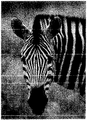
記録ヘッド21からインクを吐出するために用いる記録データは、通常のインクジェット記録装置で用いられている手法により用意することができる。本例では、次のようにして記録データを用意した。まず、入力画像データを各インク色毎の記録ヘッド21に対応するように色分解し、次に、色分解されたグレー画像データのそれぞれを誤差拡散法にて2値化した。図6は、ブラックインク吐出用の記録ヘッド21を用いた記録画像の一例の一部の拡大図である、この画像を記録するに当たり、不吐出ノズルが存在した場合には、図7のような記録結果となり、インクドットを形成すべき位置にインクドットが形成されず、記録画像上に白スジが現れて、画像品位が著しく悪化する。
【0031】
つづいて、不吐出不良ノズル情報4aに基づく記録データの作成方法について説明する。
【0032】
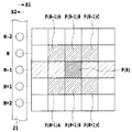
図8は本発明の基本概念図を示している。
【0033】
図8において、画素P(N)は、不吐出不良ノズルと判定されたノズル(N)によって形成すべき画素であり、この画素P(N)の記録データは、ノズル(N)の近傍に位置するノズルの記録データに対して付加する。本例の場合、画素P(N)の記録データは、ノズル(N)に隣接するノズル(N−1),(N+1)の記録データに付加されて、画素P(N)を形成する代わりに、画素P(N−1)A,P(N−1)B,P(N−1)C,P(N+1)A,P(N+1)B,P(N+1)Cを形成する。このような記録データの付加は、各ノズルからのインクの吐出および非吐出に対応すべく既に2値化されている画像データを変更することによって実現できる。そのため、装置構成が簡単に構成でき、データ処理も簡易のため、記録速度の高速化も可能となる。
【0034】
異常ノズル(不吐出、不良ノズル)によって記録すべき記録データを付加する近傍ノズルは、図8のように、異常ノズルに隣接するノズルに限る必要はない。例えば、近傍ノズルが既に記録すべき記録データを有している場合には、記録データの付加により形成すべき画素を近傍に探して、その画素を形成するように、その画素に対応するノズルにに対して記録データを付与してもよい。また、図8中における上下のノズル(N−1),(N+1)のいずれに対して記録データを付加するかについては、例えば、予め定めた上下の順にしたがったり、または、上下のノズル(N−1),(N+1)の記録データを参照して決定してもよい。いずれにしても、異常ノズルの近傍ノズルの記録データに、異常ノズルによって記録すべき記録データを付加することによって、本発明は好適に実施される。
【0035】
さらに、異常ノズルが連続して存在した場合には、それらの異常ノズルによって記録すべき記録データを、その上下の近傍ノズルの記録データに付加することによって、本発明の効果を確認することができる。また、近傍のノズルに記録データを付加する処理については、記録動作時の駆動周波数を増加させて処理することにより、近傍ノズルに予め記録すべき記録データがあるか否かに拘わらず、その近傍ノズルに対して、異常ノズルによって記録すべき記録データを簡単に付加して、本発明を好適に実施することができる。
【0036】
また、本発明は、多パス記録方式においても好適に用いることができる。多パス記録方式においては、異常ノズルを検知した後、異なる記録パス時に、その異常ノズルの記録データを他のノズルによってカバーすることが提案されている。本発明は、実質的に同一パス時に簡易な処理方法により、異常ノズルによる画質劣化を予防できるため、多パス記録方式においても有効に用いることができる。
【0037】
また、本発明は、多少のコストアップを伴うものの、インク色毎に複数の濃淡インク、および大小のドットを形成するインクジェット記録装置においても好適に用いることができる。本発明では、このような場合においても、より高次の画質を被記録媒体上に再現することができる。
【0038】
また、本発明は、特に、図2に示したようなインクジェット記録ヘッド21、つまり、複数のノズルが主走査方向と概略直角に配列されたノズル群を有し、かつ同一走査により記録することができる隣接ノズルの間隔が記録画像の各画素の間隔に対応するように、ノズルが配列された記録ヘッド21に対して、より好適に適応できる。すなわち、近傍ノズルが離れて位置した場合には、本発明は、より複雑な方法により実現されることになるため、近傍ノズルは実質的にも近接していることが望ましい。例えば、インクジェット記録方式により、ポケット写真のように小さいサイズで高画質の記録物を得る場合には、インク滴の吐出量が40pl±10程度であれば、近傍ノズルは300dpi(100μm)程度、より好ましくは、インク滴の吐出量が10pl±5程度であれば、近傍ノズルは600dpi(40μm)程度に近接していることが好ましい。さらに好ましくは、インク滴の吐出量が5pl±2程度であれば、近傍ノズルは1200dpi(20μm)程度、さらにインク滴の吐出量が2pl±1程度であれば、近傍ノズルは2400dpi(10μm)程度に近接していることが好ましい。
【0039】
このようなノズル群を比較的簡易にかつ低コストで実現するためには、以下のようなインクジェット記録方式を採用することができる。しかし、本発明は、以下に挙げる記録方式に限られるものではない。
【0040】
本発明は、特にインクジェット記録方式の中でも熱エネルギーを利用して飛翔的液滴を形成し、記録を行うインクジェット方式の記録ヘッドを用いた記録装置において優れた効果をもたらすものである。
【0041】
その代表的な構成や原理については、例えば、米国特許第4723129号明細書、同第4740796号明細書に開示されている基本的な原理を用いて行うものが好ましい。この方式は所謂オンデマンド型、コンティニュアス型のいずれにも適用可能であるが、特に、オンデマンド型の場合には、液体(インク)が保持されているシートや液路に対応して配置されている電気熱変換体に、記録情報に対応していて核沸騰を越える急速な温度上昇を与える少なくとも一つの駆動信号を印加することによって、電気熱変換体に熱エネルギを発生せしめ、記録ヘッドの熱作用面に膜沸騰を生じさせて、結果的にこの駆動信号に一体一で対応した液体(インク)内の気泡を形成出来るので有効である。この気泡の成長、収縮により吐出用開口を介して液体(インク)を吐出させて、少なくとも一つの滴を形成する。この駆動信号をパルス形状とすると、即時適切に気泡の成長収縮が行われるので、特に応答性に優れた液体(インク)の吐出が達成でき、より好ましい。このパルス形状の駆動信号としては、米国特許第4463359号明細書、同第4345262号明細書に記載されているようなものが適している。なお、上記熱作用面の温度上昇率に関する発明の米国特許第4313124号明細書に記載されている条件を採用すると、更に優れた記録を行うことが出来る。
【0042】
記録ヘッドの構成としては、上述の各明細書に開示されているような吐出口、液路、電気熱変換体の組合わせ構成(直線状液流路又は直角液流路)の他に熱作用部が屈曲する領域に配置されている構成を開示する米国特許第4558333号明細書、米国特許第4459600号明細書を用いた構成も本発明に含まれるものである。
【0043】
加えて、複数の電気熱変換体に対して、共通するスリットを電気熱変換体の吐出部とする構成を開示する特開昭59−123670号公報や熱エネルギの圧力波を吸収する開孔を吐出部に対応させる構成を開示する特開昭59−138461号公報に基いた構成としても本発明の効果は有効である。すなわち、記録ヘッドの形態がどのようなものであっても、本発明によれば記録を確実に効率よく行うことができるようになるからである。
【0044】
さらに、記録装置が記録できる記録媒体の最大幅に対応した長さを有するフルラインタイプの記録ヘッドに対しても本発明は有効に適用できる。そのような記録ヘッドとしては、複数記録ヘッドの組合せによってその長さを満たす構成や、一体的に形成された1個の記録ヘッドとしての構成のいずれでもよい。
【0045】
加えて、上例のようなシリアルタイプのものでも、装置本体に固定された記録ヘッド、あるいは装置本体に装着されることで装置本体との電気的な接続や装置本体からのインクの供給が可能になる交換自在のチップタイプの記録ヘッド、あるいは記録ヘッド自体に一体的にインクタンクが設けられたカートリッジタイプの記録ヘッドを用いた場合にも本発明は有効である。
【0046】
また、本発明の記録装置の構成として、記録ヘッドの吐出回復手段、予備的な補助手段等を付加することは本発明の効果を一層安定できるので、好ましいものである。これらを具体的に挙げれば、記録ヘッドに対してのキャッピング手段、クリーニング手段、加圧或は吸引手段、電気熱変換体或はこれとは別の加熱素子或はこれらの組み合わせを用いて加熱を行う予備加熱手段、記録とは別の吐出を行なう予備吐出手段を挙げることができる。
【0047】
本発明においては、上述した各インクに対して最も有効な形態は、上述した膜沸騰方式を実行するものである。
【0048】
【実施例】
以下、実施例により本発明をより具体的に説明する。
【0049】
(実施例1)
上述したインクジェット記録装置を用いて、上述のプリント方法により、色材を含有するY(イエロー),M(マゼンタ),C(シアン),K(ブラック)のインクを用いて画像を記録した。用いたインクジェット記録装置は、解像度が1200dpiであり、各インク滴の吐出量は4.5±0.5plである。
【0050】
色材を含有するインクの組成は以下の通りである。
(処方Yインク)
・グリセリン 5.0重量部
・チオジグリコール 5.0重量部
・尿素 5.0重量部
・イソプロピルアルコール 4.0重量部
・染料C.I.ダイレクトイエロー142 2.0重量部
・水 79.0重量部
(処方Mインク)
・グリセリン 5.0重量部
・チオジグリコール 5.0重量部
・尿素 5.0重量部
・イソプロピルアルコール 4.0重量部
・染料C.I.アシッドレッド289 2.5重量部
・水 78.5重量部
(処方Cインク)
・グリセリン 5.0重量部
・チオジグリコール 5.0重量部
・尿素 5.0重量部
・イソプロピルアルコール 4.0重量部
・染料C.I.ダイレクトブルー199 2.5重量部
・水 78.5重量部
(処方Kインク)
・グリセリン 5.0重量部
・チオジグリコール 5.0重量部
・尿素 5.0重量部
・イソプロピルアルコール 4.0重量部
・染料フードブラック2 3.0重量部
・水 78.0重量部
【0051】
被記録媒体としては、電子写真・インクジェット共用紙(PB・PAPER:キヤノン株式会社製)を用意した。これらの色材インクおよび被記録媒体を用いて記録を行った。
【0052】
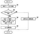
図9は、制御手順を説明するためのフローチャートである。まずは、前述した階段チャートを出力(記録)し(ステップS1)、その出力結果から、上述したように異常ノズル(不吐出、不良ノズル)を検知する(ステップS2)。異常ノズルが検知されないときは、通常の画像出力(画像記録)を実行する(ステップS3)。一方、異常ノズルが検知されたときは、後述するように、記録データを参照し、異常ノズルによって記録される記録データを近接ノズルの記録データに付加してから(ステップS4)、画像出力(画像記録)を実行する(ステップS5)。
【0053】
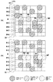
図10(a),(b)は、ステップS4の処理(記録データの補償処理)の具体的な処理内容の説明図である。これらの図は、記録ヘッド21における複数のノズル(例えば、512個)の一部と、そのノズルによって記録されるべき記録データと、の関係を示す。記録データは、インクの吐出または非吐出に対応すべく2値化された駆動信号とされており、各ノズルからインクを吐出または非吐出させるオン、オフ信号に相当する。図10(a),(b)中右側のマトリックスは、記録解像度に対応付けられており、被記録媒体上に記録されるインクドットの形成位置に対応する。本例においては、N番目のノズル(N)が異常ノズル(不吐出、不良ノズル)として判定されたとする。図10(a)において、Da〜Deは、その異常ノズル(N)によって記録されるべき記録データであり、インクを吐出させるオン信号(吐出信号)に相当する。したがって、仮に、この異常ノズル(N)によって記録されるべき記録データDa〜Deを補償する処理を施すことなく、その記録データDa〜Deのまま記録した場合には、ノズル(N)に対応する記録画像上の部位に白スジ等の画質の欠陥(Streaking)が発生することになる。
【0054】
そこで、本例においては、図10(b)のように、異常ノズル(N)によって記録されるべき記録データDa〜Deを隣接するノズル(N−1),(N+1)の記録データに付加する。すなわち、ノズル(N)の記録データDa〜Deは、記録ヘッド21の走査位置に応じて、ノズル(N−1),(N+1)の記録データに対して交互に振り分けられる。記録データDa′〜De′は、ノズル(N−1),(N+1)の記録データに付加された記録データDa〜Deであり、先の記録データDa(吐出信号)は上側の隣接ノズル(N−1)の記録データに付加され、次の記録データDb(吐出信号)は下側の隣接ノズル(N+1)の記録データに付加される。同様の処理を繰り返すことにより、記録データDc〜Deは、順次、ノズル(N−1),(N+1)の記録データに付加される。
【0055】
以下、同様の補償処理を画像データの全体に渡って施することにより、記録装置によって画像を記録した。その結果、記録画像上における白スジの発生が抑えられて、画像品位が高い記録物が得られた。
【0056】
(比較例1)
実施例1のような記録データの補償処理を行なわずに記録を実施したところ、記録画像上に白スジが発生し、画像品位の低い記録物となった。
【0057】
(実施例2)
本例においては、図11(a),(b)のような形態の記録データの補償処理を行う。
【0058】
すなわち、異常ノズル(不吐出、不良ノズル)の近傍に位置する近傍ノズルに、若干不良な不良ノズル(以下、「不良近傍ノズル」ともいう)があった場合に、その不良近傍ノズルの記録データに対してよりも正常な近傍ノズルの記録データに対して、異常ノズルによって記録されるべき記録データをより多く付加する。不良近傍ノズルは、インクの吐出不良が生じた近傍ノズルであり、例えば、インクの吐出方向が若干ずれて、インクの着弾位置が正常な位置から若干ずれるような近傍ノズルである。
【0059】
図11(a)においては、N番目のノズル(N)が異常ノズルとして判定され、それに隣接する(N−1)番目のノズル(N−1)が不良近傍ノズルとして判定されたとする。図11(a)において、Da〜Ddは、異常ノズル(N)によって記録されるべき記録データであり、またDA,DBは、不良近傍ノズル(N−1)によって記録されるべき記録データであり、これらの記録データは、インクを吐出させるオン信号(吐出信号)に相当する。本例の不良近傍ノズル(N−1)は、吐出するインクの着弾位置が正常な位置から若干ずれており、記録データDA,DBに対応するインクドットの形成位置は、正常な位置から図11(a)の上方に若干ずれる。
【0060】
本例においては、図11(b)のように、異常ノズル(N)によって記録されるべき記録データDa〜Deを隣接するノズル(N−1),(N+1)の記録データに付加する。すなわち、異常ノズル(N)によって記録されるべき記録データDa〜Deは、不良近傍ノズル(N−1)に対してよりも正常な近傍ノズル(N+1)に対して、より多く付加する。記録データDa′は、不良近傍ノズル(N−1)の記録データに付加された記録データDaであり、記録データDb′〜Dd′は,正常な近傍ノズル(N+1)の記録データに付加された記録データDb〜Ddである。このようにして、異常ノズル(N)によって記録されるべき記録データを近傍ノズルに付加することによって、その記録データが補償された記録データを作成した。
【0061】
そして、実施例1と同様に、補償処理した記録データに基づいて画像を記録した結果、実施例1と同様に階調性に優れ、白スジによる画像位の劣化の少ない良好な画像を記録することができた。また、上下の近傍ノズルに同比率で付加した場合に比べてより画質を改善させることができた。
【0062】
(実施例3)
本例においては、図12(a),(b)のような形態の記録データの補償処理を行う。すなわち、異常ノズル(不吐出、不良ノズル)の近傍に位置する複数の近傍ノズルの内、特定の近傍ノズルに対してのみ、異常ノズルによって記録されるべき記録データを付加する。
【0063】
図12(a)においては、N番目のノズル(N)が異常ノズルとして判定されたとする。図12(a)において、Da〜Ddは、異常ノズル(N)によって記録されるべき記録データであり、インクを吐出させるオン信号(吐出信号)に相当する。本例においては、図12(b)のように、異常ノズル(N)によって記録されるべき記録データDa〜Ddを下側に隣接する近傍ノズル(N+1)の記録データに対してのみ付加する。記録データDa′〜Dd′は、その近傍ノズル(N+1)の記録データに付加された記録データDa〜Ddである。このようにして、異常ノズル(N)によって記録されるべき記録データを近傍ノズルに付加することによって、その記録データが補償された記録データを作成した。
【0064】
そして、実施例1と同様に、補償処理した記録データに基づいて画像を記録した結果、実施例1と同様に階調性に優れ、白スジによる画像位の劣化の少ない良好な画像を記録することができた。また、上下の近傍ノズルに同比率で付加した場合に比べて、特に、線画の細かいタッチをより良く表現して、画質を改善させることができた。
【0065】
(実施例4)
本例においては、図13(a),(b)のような形態の記録データの補償処理を行う。すなわち、補償処理後の記録データのデータ密度(記録解像度)を補償前の記録データのデータ密度よりも高める。
【0066】
図13(a)においては、N番目のノズル(N)が異常ノズル(不吐出、不良ノズル)として判定されたとする。図13(a)において、Da〜Deは、異常ノズル(N)によって記録されるべき記録データであり、インクを吐出させるオン信号(吐出信号)に相当する。本例においては、図13(b)のように、異常ノズル(N)によって記録されるべき記録データDa〜Deを近傍ノズル(N−1),(N+1)の記録データに対して付加することにより、記録データDa〜Deを補償する。記録データDa′〜De′は、その近傍ノズル((N−1),N+1)の記録データに付加された記録データDa〜Deである。ただし、その補償処理後における図13(b)の記録データのデータ密度は、補償処理前における図13(a)の記録データのデータ密度の2倍とする。そして、近傍ノズル(N−1),(N+1)に元々対応付けられた記録データと、それらの近傍ノズル(N−1),(N+1)が補償する記録データDa〜Deと、の重複を避ける。
【0067】
記録動作時には、記録ヘッド21におけるインク滴の吐出駆動周波数を通常の2倍とする。そして、近傍ノズル(N−1),(N+1)が元々の記録データに基づいてインクを吐出するタイミングと、それらの近傍ノズル(N−1),(N+1)に付加された記録データDa′〜De′に基づいてインクを吐出タイミングと、をずらして、それらの重複を避ける。したがって、実施例1の場合と同様に、単純に記録データを付加することができる。
【0068】
そして、実施例1と同様に、補償処理した記録データに基づいて画像を記録した結果、実施例1と同様に階調性に優れ、白スジによる画像位の劣化の少ない良好な画像を記録することができた。本例の場合は、近傍ノズルに対応する記録データに対して、異常ノズルに対応する記録データを付加させたときに、記録ヘッド21の記録解像度を高めることになる。
【0069】
(実施例5)
実施例1から4において、画像を記録するインクジェット記録装置として、ノズルが1200dpiの解像度で配列された記録ヘッド21を用い、各ノズルから吐出するインク滴を4.5±0.5plの記録ヘッドで印字した。この場合も、記録画像の画質は改善した。記録画像として、高画質なポケット写真を選んだ場合、その効果は十分であった。、またA4サイズのプリント物を作成して、それを遠目に観察するとさらに効果的であった。
【0070】
本発明は、特に、不吐出、不良ノズルと近傍ノズルとの間隔が接近する場合に有効であり、さらに、その間隔が着弾したインクドット径に対して小さい方がより有効である。
【0071】
(比較例2)
また、ノズルが600dpiの解像度で配列された記録ヘッド21を用い、各ノズルから吐出するインク滴を4.5±0.5plとした場合には、記録画像の画質は改善した。しかし、記録画像として、高画質なポケット写真を選んだ場合に、その効果が十分とはいいずらかった。
【0072】
(他の実施例)
また、複数の近傍ノズルに対応する記録データに対して、異常ノズルに対応する記録データを分散させるようにして付加させてもよい。その場合には、記録すべき画像の種類に応じて、記録データを分散させる割合を変更してもよい。
【0073】
また、複数の近傍ノズルに対応する記録データに対して、異常ノズルに対応する記録データを付加させる形態(記録データの補償形態)は、被記録媒体の種類に応じて異ならせてもよい。
【0074】
また、複数のノズルの並び方向におけるN番目のノズルが異常ノズルであるときは、N番目の異常ノズルの近傍に位置する(N−M)番目の近傍ノズルまたは(N+M)番目の近傍ノズルに対応する記録データの少なくとも一方に対して(ただし、N,Mは正の整数)、異常ノズルに対応する記録データを付加することができる。その場合には、前述した実施例と同様に、近傍ノズルの複数に対応する記録データに対して、異常ノズルに対応する記録データを付加する比率は、近傍ノズルの状態により決定してもよい。その近傍ノズルの状態は、その近傍ノズルから吐出されて被記録媒体上に着弾するインクの着弾情報から得ることができる。その着弾情報としては、被記録媒体上に着弾するインクの着弾位置または被記録媒体上に形成されるインクのドット径の情報の少なくとも一方を含ませることができる。
【0075】
【発明の効果】
以上説明したように、本発明は、インクの吐出状態に異常が生じた異常ノズルがある場合に、その異常ノズルに対応する記録データを、その異常ノズルの近傍に位置する近傍ノズルに対応する記録データに付加することにより、その異常ノズルに対応する記録データを保障して、異常ノズルが存在した場合にも高品位な画像を記録することができる。したがって、記録時間を長くすることなく、記録画像上の白スジなどに起因する画像品位の低下を伴うことなく、スムーズなグラデーションを表現することもできる。
【0076】
また、記録ヘッドに異常ノズルが生じた場合に、それを新規なものと直ちに交換する必要がなく、記録ヘッドを長期に渡って使用することができる。このことは、エコロジーの観点からも望ましい。
【0077】
また、記録データとして、ノズルからのインクの吐出、非吐出に対応する駆動データを用いることにより、画像の階調データに遡って処理する場合よりも、比較的にデータ量が軽微な駆動信号を処理することになり、その分、処理速度の高速化が可能となる。例えば、2値化後の記録データを処理対象として、近傍ノズルに対応する記録データの空き位置に、異常ノズルに対応する記録データを追加することができる。
【0078】
また、本発明は、1パス記録方式においても効果的に適用することができると共に、多パス記録方式においても、簡易なデータ処理によって、白スジなどによる画質の劣化を低減することができて有用である。
【図面の簡単な説明】
【図1】本発明の一実施形態に係るインクジェット記録装置の概略を示す正面図である。
【図2】図1における記録ヘッドの構成例の説明図である。
【図3】図1のインクジェット記録装置の制御系を説明するためのブロック構成図である。
【図4】本発明の一実施形態において、異常ノズルを検知するため用いる記録パターンの説明図である。
【図5】図4の記録パターンと、異常ノズルとの関係の説明図である。
【図6】通常の2値画像の記録例を示す図である。
【図7】不吐出、不良ノズルがある記録ヘッドによって、図2の2値画像を記録した場合の説明図である。
【図8】本発明の一実施形態において、異常ノズルによって記録されるべき記録データを補償する場合の補償方法を説明するための概念図である。
【図9】本発明の実施例1における記録動作を説明するためのフローチャートである。
【図10】(a)は、本発明の実施例1における補償前の記録データの説明図、(b)は、本発明の実施例1における補償後の記録データの説明である。
【図11】(a)は、本発明の実施例2における補償前の記録データの説明図、(b)は、本発明の実施例2における補償後の記録データの説明である。
【図12】(a)は、本発明の実施例3における補償前の記録データの説明図、(b)は、本発明の実施例3における補償後の記録データの説明である。
【図13】(a)は、本発明の実施例4における補償前の記録データの説明図、(b)は、本発明の実施例4における補償後の記録データの説明である。
【符号の説明】
1 画像データ入力部
2 操作部
3 CPU
4 記憶媒体
4a 不吐出不良ノズル情報
4b 制御プログラム群
5 RAM
6 画像データ処理部
7 画像記録部
8 バス部
20 キャリッジ
21 インクジェット記録ヘッド
22 インクカートリッジ
23 フレキシブルケーブル
24 被記録媒体
25 排紙ローラ
26 搬送モータ
27 ガイドシャフト
28 リニアエンコーダ
29 駆動ベルト
30 キャリッジモータ
31 キャップ部
32 回復ユニット
33 インク受け部[0001]
BACKGROUND OF THE INVENTION
The present invention relates to an ink jet recording method and an ink jet recording apparatus for recording an image using a recording head capable of ejecting ink.
[0002]
The present invention can be applied to all devices using various recording media such as paper, cloth, leather, non-woven fabric, OHP paper, and metal. Specific application equipment includes office equipment such as printers, copiers, and facsimile machines, and industrial production equipment.
[0003]
[Prior art]
As an output device for image formation (recording) in copiers, information processing devices such as word processors and computers, and communication devices has become widespread, ink jet recording digital images by an ink jet method Recording devices are rapidly spreading. In such a recording apparatus, in order to improve the recording speed, a recording head in which a plurality of ink discharge nozzles and liquid paths are integrated is used as a recording head in which a plurality of ink discharge nozzles are integrated and arranged. Furthermore, in recent years, as the use of color images has progressed, many recording apparatuses that include a plurality of such recording heads have been seen.
[0004]
The ink jet recording method performs recording on a recording medium by ejecting ink, which is a recording liquid, as droplets from a recording head and landing the ink on a recording medium such as paper to form ink dots. In addition, since it is a non-contact method in which the recording head and the recording medium do not come into contact with each other, noise can be reduced. In addition, by increasing the density of the ink ejection nozzles, it is possible to increase the resolution of the recorded image and increase the recording speed. Furthermore, special processing such as phenomenon and fixing can be performed on the recording medium such as plain paper. In recent years, such an ink jet recording method has become widespread because it is possible to record a high-quality image at a low price. In particular, an on-demand type ink jet recording apparatus is promising for future demand because it can be easily colored and the apparatus itself can be miniaturized and simplified. Further, with the colorization of the recorded image as described above, there is an increasing demand for higher image quality and higher recording speed of the recorded image.
[0005]
[Problems to be solved by the invention]
However, the conventional method has the following various problems.
[0006]
When using a recording head in which a plurality of ink ejection nozzles are integrated and arranged, if one or more ink ejection nozzles are clogged or cannot be driven for some reason, Ink dots to be formed by the nozzles are not formed on the recording medium material. As a result, white streaks due to non-ejection of ink occur on the recorded image, and the image quality may be significantly degraded. Also, when one or a plurality of ejection nozzles ejects ink that is significantly different from other normal ejection nozzles, that is, when ink ejection failure occurs for some reason, white streaks appear on the recorded image. Or due to non-uniform recording density, streaks with non-uniform recording density may occur on the recorded image, resulting in a significant reduction in image quality.
[0007]
Further, as a recording method for preferentially improving the quality of a recorded image, there is a method of attempting to recover the ink ejection state by a cleaning mechanism when ink ejection failure or ejection failure occurs in a nozzle. Alternatively, in the case of a multi-pass method in which a recording image is completed by a plurality of passes (recording scanning) of the recording head, nozzles that do not eject ink and nozzles that fail to eject ink (hereinafter referred to as “no-ejection nozzles”) are used. A method of substituting these also for “non-ejection, defective nozzle” or “abnormal nozzle” has been proposed. However, when the former is accompanied by a recovery operation due to cleaning, this leads to an increase in cost such as cleaning time and ink consumption, and it is difficult to reflect the intention to reduce ink consumption as much as possible from an ecological point of view. In the latter multi-pass method, a long recording time is required.
[0008]
In the future, inkjet recording devices will be required to solve the above-mentioned various conventional problems and simultaneously achieve higher recording speed and lower cost in addition to higher image quality of recorded images. It is done.
[0009]
An object of the present invention is to provide an ink jet recording method and an ink jet recording apparatus capable of recording a high-quality image even when an abnormality occurs in an ink ejection state at a nozzle.
[0010]
[Means for Solving the Problems]
The inkjet recording method of the present invention is an inkjet recording method in which recording is performed by ejecting ink from the nozzles based on recording data using a recording head in which a plurality of nozzles capable of ejecting ink is formed. A specifying step for identifying abnormal nozzles that do not eject ink, a determination step for determining ink ejection states of a plurality of neighboring nozzles located in the vicinity of the abnormal nozzle, and recording data corresponding to the abnormal nozzles in the plurality of neighborhoods The recording data corresponding to the abnormal nozzle is added to the recording data corresponding to the nozzle, and when it is determined in the determination step that there is a defective nozzle having a poor ink ejection state among the plurality of neighboring nozzles. An additional step of adding more to the print data corresponding to other neighboring nozzles than to the print data corresponding to the defective nozzle It is characterized by that.
[0011]
An inkjet recording apparatus according to the present invention uses an inkjet recording apparatus in which a plurality of nozzles capable of ejecting ink are formed, and performs recording by ejecting ink from the nozzles based on recording data. Identifying means for identifying abnormal nozzles that do not eject ink; determining means for determining ink ejection states of a plurality of neighboring nozzles located in the vicinity of the abnormal nozzle; and recording data corresponding to the abnormal nozzles in the plurality of neighboring areas The recording data corresponding to the abnormal nozzle is added to the recording data corresponding to the nozzle, and when it is determined in the determination step that there is a defective nozzle having a poor ink ejection state among the plurality of neighboring nozzles. Adding means for adding more to recording data corresponding to other neighboring nozzles than to recording data corresponding to the defective nozzle It is characterized by that.
[0012]
DETAILED DESCRIPTION OF THE INVENTION
Hereinafter, exemplary embodiments of the present invention will be described in detail with reference to the drawings.
[0013]
FIG. 1 is a front view showing an outline of an ink jet recording apparatus according to an embodiment of the present invention. A plurality of ink jet recording heads 21-1 to 21-4 are mounted on the
[0014]
Control signals and the like to the
[0015]
A
[0016]
The cap unit 31 is also used for a discharge recovery process and a suction recovery process for maintaining a good ink discharge state in the
[0017]
FIG. 2 is an explanatory diagram of a schematic configuration of the
[0018]
In FIG. 2, the
[0019]
The ink jet recording method applicable to the present invention is not limited to the bubble jet (registered trademark) method using a heating element (heater). For example, in the case of a continuous type in which ink droplets are continuously ejected into particles, it can be applied to a charge control type, a divergence control type, etc., and in the case of an on-demand type in which ink droplets are ejected as necessary. Is applicable to a pressure control system that ejects ink droplets from an orifice by mechanical vibration of a piezoelectric vibration element.
[0020]
FIG. 3 is a block diagram showing an example of the configuration of the control system in the ink jet recording apparatus of the present invention.
[0021]
In FIG. 3, 1 is an image data input unit, 2 is an operation unit, 3 is a CPU for performing various processes, and 4 is a storage medium for storing various data. Reference numeral 4a denotes ink ejection failure nozzle information relating to each nozzle formed by each ink discharge port, and 4b denotes various control program groups.
[0022]
More specifically,
[0023]
6 is an image data process for quantizing the input multi-value image data into N-value image data for each pixel and creating an ejection pattern corresponding to the gradation value “T” indicated by each quantized pixel. Part. That is, the image data processing unit 6 performs N-value processing on the input multi-value image data, and then creates an ejection pattern corresponding to the gradation value “T”. For example, when multi-value image data expressed in 8 bits (256 gradations) is input to the image
[0024]
An image recording unit 7 forms a dot image on a recording medium by ejecting ink from the nozzles of the
[0025]
Next, the non-ejection defective nozzle information 4a of the
[0026]
First, in order to know the state of the nozzles in the
[0027]
When there is a non-ejection nozzle that does not eject ink, a short linear pattern corresponding to the non-ejection nozzle is not recorded. Therefore, non-ejection nozzles that do not eject ink can be determined based on the image pattern recording result of FIG. Specifically, the number of nozzles that are non-ejection nozzles is detected by reading an image from the recorded image pattern (step chart) of FIG. 4 using a sensor that can be read and scanned (not shown). be able to. The detection result becomes non-ejection nozzle information. Alternatively, the non-ejection nozzle may be determined visually without using a sensor, and the information may be created as non-ejection nozzle information and input to the recording apparatus. This non-ejection nozzle information is prepared for each
[0028]
Further, when there is a defective nozzle in which an ink ejection defect has occurred, a defect such as the linearity not being maintained appears in a short linear pattern corresponding to the defective nozzle. Therefore, it is possible to determine from the stair chart as the recorded image pattern in FIG. 4 nozzles in which the linearity of the short linear pattern is not significantly maintained and nozzles in which the ink ejection state is not stable. These nozzles are defective nozzles that have poor ink ejection. In the case of the stair chart of FIG. 5, since the short linear patterns P28 and P30 corresponding to the nozzles N28 and N30 are abnormal, the nozzles N28 and N30 are determined as defective nozzles.
[0029]
The defective nozzle is preferably not used for image recording in order to obtain a good recorded matter. Such defective nozzles can be prevented from being used for image recording by being handled in the same manner as non-ejection nozzles. For that purpose, information on what number nozzle is a defective nozzle (defective nozzle information) may be handled in addition to the non-ejection nozzle information. In the case of this example, non-ejection nozzle information and defective nozzle information are handled as non-ejection defective nozzle information 4a (see FIG. 3). Therefore, in the case of the stair chart of FIG. 5, the 18th, 28th, and 30th nozzles N18, N28, and N30 are stored as the non-ejection defective nozzle information 4a.
[0030]
The recording data used for ejecting ink from the
[0031]
Next, a method for creating recording data based on the non-ejection defective nozzle information 4a will be described.
[0032]
FIG. 8 shows a basic conceptual diagram of the present invention.
[0033]
In FIG. 8, a pixel P (N) is a pixel to be formed by the nozzle (N) determined to be a non-ejection defective nozzle, and the recording data of this pixel P (N) is located in the vicinity of the nozzle (N). This is added to the recording data of the nozzle to be used. In this example, the recording data of the pixel P (N) is added to the recording data of the nozzles (N−1) and (N + 1) adjacent to the nozzle (N) to form the pixel P (N). Pixels P (N-1) A, P (N-1) B, P (N-1) C, P (N + 1) A, P (N + 1) B, and P (N + 1) C are formed. Such addition of recording data can be realized by changing image data that has already been binarized so as to correspond to ejection and non-ejection of ink from each nozzle. Therefore, the apparatus configuration can be easily configured and the data processing is also simplified, so that the recording speed can be increased.
[0034]
The neighboring nozzles to which the recording data to be recorded by the abnormal nozzles (non-ejection and defective nozzles) need not be limited to the nozzles adjacent to the abnormal nozzles as shown in FIG. For example, if the neighboring nozzle already has recording data to be recorded, the nozzle corresponding to the pixel is formed so that the pixel to be formed is searched in the vicinity by adding the recording data and the pixel is formed. Recording data may be assigned to the. In addition, as to which of the upper and lower nozzles (N−1) and (N + 1) in FIG. 8 is to be added with the print data, for example, the predetermined upper and lower order or the upper and lower nozzles (N -1) and (N + 1) may be determined with reference to the recording data. In any case, the present invention is preferably implemented by adding the recording data to be recorded by the abnormal nozzle to the recording data of the nozzle near the abnormal nozzle.
[0035]
Furthermore, when abnormal nozzles exist continuously, the effect of the present invention can be confirmed by adding the recording data to be recorded by these abnormal nozzles to the recording data of the upper and lower neighboring nozzles. . In addition, the process of adding print data to the neighboring nozzles is performed by increasing the drive frequency at the time of printing operation, regardless of whether there is print data to be recorded in advance in the neighboring nozzles. The present invention can be suitably implemented by simply adding recording data to be recorded by the abnormal nozzle to the nozzle.
[0036]
The present invention can also be suitably used in a multi-pass recording system. In the multi-pass printing method, after detecting an abnormal nozzle, it has been proposed to cover the recording data of the abnormal nozzle with another nozzle during different printing passes. Since the present invention can prevent image quality deterioration due to abnormal nozzles by a simple processing method during substantially the same pass, it can also be used effectively in a multi-pass printing system.
[0037]
Further, the present invention can be suitably used also in an ink jet recording apparatus that forms a plurality of dark and light inks and large and small dots for each ink color, although with some cost increase. In the present invention, even in such a case, higher-order image quality can be reproduced on the recording medium.
[0038]
In addition, the present invention particularly has an
[0039]
In order to realize such a nozzle group relatively easily and at low cost, the following ink jet recording method can be employed. However, the present invention is not limited to the following recording methods.
[0040]
The present invention provides an excellent effect particularly in a recording apparatus using an ink jet recording head that performs recording by forming flying droplets using thermal energy among ink jet recording methods.
[0041]
As its typical configuration and principle, for example, those performed using the basic principle disclosed in US Pat. Nos. 4,723,129 and 4,740,796 are preferable. This method can be applied to both the so-called on-demand type and continuous type. In particular, in the case of the on-demand type, it is arranged corresponding to the sheet or liquid path holding the liquid (ink). By applying at least one drive signal corresponding to the recording information and giving a rapid temperature rise exceeding nucleate boiling to the electrothermal transducer, the thermal energy is generated in the electrothermal transducer, and the recording head This is effective because film boiling occurs on the heat acting surface, and as a result, bubbles in the liquid (ink) corresponding to the drive signal can be formed. By the growth and contraction of the bubbles, liquid (ink) is ejected through the ejection opening to form at least one droplet. It is more preferable that the drive signal has a pulse shape, since the bubble growth and contraction is performed immediately and appropriately, and thus it is possible to achieve discharge of a liquid (ink) having particularly excellent responsiveness. As this pulse-shaped drive signal, those described in US Pat. Nos. 4,463,359 and 4,345,262 are suitable. Further excellent recording can be performed by employing the conditions described in US Pat. No. 4,313,124 of the invention relating to the temperature rise rate of the heat acting surface.
[0042]
As the configuration of the recording head, in addition to the combination configuration (straight liquid channel or right-angle liquid channel) of the discharge port, the liquid channel, and the electrothermal transducer as disclosed in each of the above-mentioned specifications, the thermal action A configuration using US Pat. No. 4,558,333 and US Pat. No. 4,459,600, which disclose a configuration in which the portion is arranged in a bent region, is also included in the present invention.
[0043]
In addition, for a plurality of electrothermal transducers, Japanese Patent Application Laid-Open No. Sho 59-123670 that discloses a configuration in which a common slit is used as a discharge portion of the electrothermal transducer or an aperture that absorbs pressure waves of thermal energy is provided. The effect of the present invention is also effective as a configuration based on Japanese Patent Application Laid-Open No. 59-138461 which discloses a configuration corresponding to the discharge unit. That is, whatever the form of the recording head is, according to the present invention, recording can be performed reliably and efficiently.
[0044]
Furthermore, the present invention can be effectively applied to a full-line type recording head having a length corresponding to the maximum width of a recording medium that can be recorded by the recording apparatus. As such a recording head, either a configuration satisfying the length by a combination of a plurality of recording heads or a configuration as a single recording head formed integrally may be used.
[0045]
In addition, even the serial type as shown in the above example can be connected to the main body of the recording head or attached to the main body of the device so that electrical connection with the main body of the device and ink supply from the main body are possible. The present invention is also effective when a replaceable chip type recording head or a cartridge type recording head in which an ink tank is integrally provided in the recording head itself is used.
[0046]
In addition, it is preferable to add a recording head ejection recovery means, a preliminary auxiliary means, and the like as the configuration of the recording apparatus of the present invention, since the effects of the present invention can be further stabilized. Specifically, heating is performed using a capping unit, a cleaning unit, a pressurizing or suction unit, an electrothermal transducer, a heating element different from this, or a combination thereof. Examples thereof include a preliminary heating unit for performing the discharge and a preliminary discharge unit for performing discharge different from the recording.
[0047]
In the present invention, the most effective form for each of the above-described inks is to execute the above-described film boiling method.
[0048]
【Example】
Hereinafter, the present invention will be described more specifically with reference to examples.
[0049]
(Example 1)
Using the above-described ink jet recording apparatus, an image was recorded using Y (yellow), M (magenta), C (cyan), and K (black) inks containing a color material by the above-described printing method. The used ink jet recording apparatus has a resolution of 1200 dpi, and the ejection amount of each ink droplet is 4.5 ± 0.5 pl.
[0050]
The composition of the ink containing the color material is as follows.
(Prescription Y ink)
・ Glycerin 5.0 parts by weight
・ Thiodiglycol 5.0 parts by weight
・ 5.0 parts by weight of urea
・ Isopropyl alcohol 4.0 parts by weight
Dye C. I. Direct Yellow 142 2.0 parts by weight
・ 79.0 parts by weight of water
(Prescription M ink)
・ Glycerin 5.0 parts by weight
・ Thiodiglycol 5.0 parts by weight
・ 5.0 parts by weight of urea
・ Isopropyl alcohol 4.0 parts by weight
Dye C. I. Acid Red 289 2.5 parts by weight
・ 78.5 parts by weight of water
(Prescription C ink)
・ Glycerin 5.0 parts by weight
・ Thiodiglycol 5.0 parts by weight
・ 5.0 parts by weight of urea
・ Isopropyl alcohol 4.0 parts by weight
Dye C. I. Direct Blue 199 2.5 parts by weight
・ 78.5 parts by weight of water
(Prescription K ink)
・ Glycerin 5.0 parts by weight
・ Thiodiglycol 5.0 parts by weight
・ 5.0 parts by weight of urea
・ Isopropyl alcohol 4.0 parts by weight
・
・ Water 78.0 parts by weight
[0051]
An electrophotographic / inkjet paper (PB / PAPER: manufactured by Canon Inc.) was prepared as a recording medium. Recording was performed using these color material inks and a recording medium.
[0052]
FIG. 9 is a flowchart for explaining the control procedure. First, the above-described stair chart is output (recorded) (step S1), and abnormal nozzles (non-ejection and defective nozzles) are detected from the output result as described above (step S2). When no abnormal nozzle is detected, normal image output (image recording) is executed (step S3). On the other hand, when an abnormal nozzle is detected, as described later, the recording data is referred to, the recording data recorded by the abnormal nozzle is added to the recording data of the adjacent nozzle (step S4), and then the image output (image Recording) is executed (step S5).
[0053]
FIGS. 10A and 10B are explanatory diagrams of specific processing contents of the processing in step S4 (recording data compensation processing). These drawings show the relationship between a part of a plurality of nozzles (for example, 512) in the
[0054]
Therefore, in this example, as shown in FIG. 10B, the recording data Da to De to be recorded by the abnormal nozzle (N) are added to the recording data of the adjacent nozzles (N−1) and (N + 1). . That is, the recording data Da to De of the nozzle (N) are alternately distributed to the recording data of the nozzles (N−1) and (N + 1) according to the scanning position of the
[0055]
Thereafter, an image was recorded by the recording device by performing the same compensation process over the entire image data. As a result, the occurrence of white streaks on the recorded image was suppressed, and a recorded matter with high image quality was obtained.
[0056]
(Comparative Example 1)
When recording was performed without performing compensation processing for the recording data as in Example 1, white streaks occurred on the recorded image, resulting in a recorded product with low image quality.
[0057]
(Example 2)
In this example, compensation processing for recording data in the form as shown in FIGS. 11A and 11B is performed.
[0058]
That is, when there is a slightly defective nozzle (hereinafter, also referred to as “near defect nozzle”) in the vicinity of the nozzle located in the vicinity of the abnormal nozzle (non-ejection, defective nozzle), the recording data of the nozzle near the defect is recorded. On the other hand, more recording data to be recorded by the abnormal nozzles is added to the recording data of the normal neighboring nozzles. The defective vicinity nozzle is a vicinity nozzle in which an ink discharge failure has occurred, for example, a vicinity nozzle in which the ink discharge direction is slightly shifted and the ink landing position is slightly deviated from the normal position.
[0059]
In FIG. 11A, it is assumed that the Nth nozzle (N) is determined as an abnormal nozzle, and the (N-1) th nozzle (N-1) adjacent thereto is determined as a defective vicinity nozzle. In FIG. 11A, Da to Dd are recording data to be recorded by the abnormal nozzle (N), and DA and DB are recording data to be recorded by the defective neighboring nozzle (N-1). These recording data correspond to ON signals (ejection signals) for ejecting ink. In the defective vicinity nozzle (N-1) of this example, the landing position of the ejected ink is slightly shifted from the normal position, and the ink dot formation position corresponding to the recording data DA and DB is from the normal position in FIG. Slightly above (a).
[0060]
In this example, as shown in FIG. 11B, the recording data Da to De to be recorded by the abnormal nozzle (N) are added to the recording data of the adjacent nozzles (N−1) and (N + 1). In other words, the recording data Da to De to be recorded by the abnormal nozzle (N) is added more to the normal neighboring nozzle (N + 1) than to the defective neighboring nozzle (N-1). The recording data Da ′ is the recording data Da added to the recording data of the defective neighboring nozzle (N−1), and the recording data Db ′ to Dd ′ are added to the recording data of the normal neighboring nozzle (N + 1). Recording data Db to Dd. In this way, the recording data to be recorded by the abnormal nozzle (N) is added to the neighboring nozzles, thereby generating the recording data in which the recording data is compensated.
[0061]
As in the first embodiment, an image is recorded based on the compensated recording data. As a result, a good image with excellent gradation and little image degradation due to white stripes is recorded as in the first embodiment. I was able to. In addition, the image quality could be improved more than when the same ratio was added to the upper and lower neighboring nozzles.
[0062]
(Example 3)
In this example, compensation processing of recording data in the form as shown in FIGS. 12A and 12B is performed. That is, recording data to be recorded by the abnormal nozzle is added only to a specific neighboring nozzle among a plurality of neighboring nozzles located in the vicinity of the abnormal nozzle (non-ejection, defective nozzle).
[0063]
In FIG. 12A, it is assumed that the Nth nozzle (N) is determined as an abnormal nozzle. In FIG. 12A, Da to Dd are recording data to be recorded by the abnormal nozzle (N), and correspond to an on signal (ejection signal) for ejecting ink. In this example, as shown in FIG. 12B, the recording data Da to Dd to be recorded by the abnormal nozzle (N) is added only to the recording data of the neighboring nozzle (N + 1) adjacent to the lower side. The recording data Da ′ to Dd ′ are recording data Da to Dd added to the recording data of the neighboring nozzle (N + 1). In this way, the recording data to be recorded by the abnormal nozzle (N) is added to the neighboring nozzles, thereby generating the recording data in which the recording data is compensated.
[0064]
As in the first embodiment, an image is recorded based on the compensated recording data. As a result, a good image with excellent gradation and little image degradation due to white stripes is recorded as in the first embodiment. I was able to. Compared with the case where the nozzles are added at the same ratio to the upper and lower neighboring nozzles, the fine touch of the line drawing can be expressed better and the image quality can be improved.
[0065]
Example 4
In this example, compensation processing for recording data in the form as shown in FIGS. 13A and 13B is performed. That is, the data density (recording resolution) of the recording data after the compensation process is made higher than the data density of the recording data before the compensation.
[0066]
In FIG. 13A, it is assumed that the Nth nozzle (N) is determined as an abnormal nozzle (non-ejection, defective nozzle). In FIG. 13A, Da to De are recording data to be recorded by the abnormal nozzle (N) and correspond to ON signals (ejection signals) for ejecting ink. In this example, as shown in FIG. 13B, the recording data Da to De to be recorded by the abnormal nozzle (N) is added to the recording data of the neighboring nozzles (N−1) and (N + 1). Thus, the recording data Da to De are compensated. The recording data Da ′ to De ′ are the recording data Da to De added to the recording data of the neighboring nozzles ((N−1), N + 1). However, the data density of the recording data in FIG. 13B after the compensation processing is twice the data density of the recording data in FIG. 13A before the compensation processing. The recording data originally associated with the neighboring nozzles (N−1) and (N + 1) and the recording data Da to De compensated by the neighboring nozzles (N−1) and (N + 1) are avoided. .
[0067]
At the time of the recording operation, the ink droplet ejection driving frequency in the
[0068]
As in the first embodiment, an image is recorded based on the compensated recording data. As a result, a good image with excellent gradation and little image degradation due to white stripes is recorded as in the first embodiment. I was able to. In the case of this example, the recording resolution of the
[0069]
(Example 5)
In Examples 1 to 4, a
[0070]
The present invention is particularly effective when the interval between the non-ejection and defective nozzles and the neighboring nozzles is close, and it is more effective that the interval is smaller than the landed ink dot diameter.
[0071]
(Comparative Example 2)
Further, when the
[0072]
(Other examples)
Further, the recording data corresponding to the abnormal nozzles may be added to the recording data corresponding to the plurality of neighboring nozzles so as to be dispersed. In that case, the ratio of distributing the recording data may be changed according to the type of image to be recorded.
[0073]
Further, the form (recording data compensation form) of adding the recording data corresponding to the abnormal nozzle to the recording data corresponding to the plurality of neighboring nozzles may be different depending on the type of the recording medium.
[0074]
When the Nth nozzle in the arrangement direction of the plurality of nozzles is an abnormal nozzle, it corresponds to the (N−M) th neighboring nozzle or the (N + M) th neighboring nozzle located in the vicinity of the Nth abnormal nozzle. The recording data corresponding to the abnormal nozzle can be added to at least one of the recording data to be performed (where N and M are positive integers). In that case, as in the above-described embodiment, the ratio of adding the recording data corresponding to the abnormal nozzle to the recording data corresponding to a plurality of the adjacent nozzles may be determined according to the state of the adjacent nozzle. The state of the neighboring nozzle can be obtained from the landing information of the ink ejected from the neighboring nozzle and landed on the recording medium. The landing information can include at least one of information on the landing position of the ink landing on the recording medium and the dot diameter of the ink formed on the recording medium.
[0075]
【The invention's effect】
As described above, according to the present invention, when there is an abnormal nozzle in which an abnormality has occurred in the ink ejection state, the recording data corresponding to the abnormal nozzle is recorded as the recording corresponding to the neighboring nozzle located in the vicinity of the abnormal nozzle. By adding to the data, it is possible to guarantee the recording data corresponding to the abnormal nozzle and to record a high-quality image even when the abnormal nozzle exists. Therefore, a smooth gradation can be expressed without increasing the recording time and without deteriorating the image quality due to white stripes on the recorded image.
[0076]
Further, when an abnormal nozzle occurs in the recording head, it is not necessary to immediately replace it with a new one, and the recording head can be used for a long period of time. This is also desirable from an ecological point of view.
[0077]
In addition, by using drive data corresponding to ejection and non-ejection of ink from the nozzles as recording data, a drive signal with a relatively small amount of data can be obtained compared to the case of processing retroactively to the gradation data of the image. Therefore, the processing speed can be increased accordingly. For example, print data corresponding to an abnormal nozzle can be added to a vacant position of print data corresponding to a neighboring nozzle, with binarized print data as a processing target.
[0078]
In addition, the present invention can be effectively applied to a one-pass printing method, and can be useful in a multi-pass printing method because image quality deterioration due to white stripes can be reduced by simple data processing. It is.
[Brief description of the drawings]
FIG. 1 is a front view showing an outline of an ink jet recording apparatus according to an embodiment of the present invention.
FIG. 2 is an explanatory diagram of a configuration example of a recording head in FIG.
3 is a block configuration diagram for explaining a control system of the ink jet recording apparatus of FIG. 1; FIG.
FIG. 4 is an explanatory diagram of a recording pattern used for detecting an abnormal nozzle in an embodiment of the present invention.
FIG. 5 is an explanatory diagram of a relationship between the recording pattern of FIG. 4 and abnormal nozzles.
FIG. 6 is a diagram illustrating a recording example of a normal binary image.
7 is an explanatory diagram when the binary image of FIG. 2 is recorded by a recording head having non-ejection and defective nozzles.
FIG. 8 is a conceptual diagram for explaining a compensation method when compensating print data to be printed by an abnormal nozzle in an embodiment of the present invention.
FIG. 9 is a flowchart for explaining a recording operation in
10A is an explanatory diagram of recording data before compensation in
11A is an explanatory diagram of recording data before compensation in
12A is an explanatory diagram of recording data before compensation in
13A is an explanatory diagram of recording data before compensation in
[Explanation of symbols]
1 Image data input section
2 Operation part
3 CPU
4 storage media
4a No-discharge defective nozzle information
4b Control program group
5 RAM
6 Image data processor
7 Image recording unit
8 bus club
20 Carriage
21 Inkjet recording head
22 Ink cartridge
23 Flexible cable
24 Recording medium
25 Paper discharge roller
26 Conveyor motor
27 Guide shaft
28 Linear encoder
29 Drive belt
30 Carriage motor
31 Cap part
32 Recovery Unit
33 Ink receiving part
Claims (18)
インクを吐出しない異常ノズルを特定する特定工程と、
前記異常ノズルの近傍に位置する複数の近傍ノズルのインクの吐出状態を判定する判定工程と、
前記異常ノズルに対応する記録データを前記複数の近傍ノズルに対応する記録データに付加し、かつ前記判定工程において前記複数の近傍ノズルの中にインクの吐出状態が不良な不良ノズルが存在すると判定された場合には、前記異常ノズルに対応する記録データを、前記不良ノズルに対応する記録データに対してよりも他の近傍ノズルに対応する記録データに対してより多く付加する付加工程と、
を有することを特徴とするインクジェット記録方法。In an inkjet recording method in which recording is performed by ejecting ink from the nozzles based on recording data using a recording head in which a plurality of nozzles capable of ejecting ink are formed.
A specific process for identifying abnormal nozzles that do not eject ink;
A determination step of determining an ink ejection state of a plurality of neighboring nozzles located in the vicinity of the abnormal nozzle;
The recording data corresponding to the abnormal nozzle is added to the recording data corresponding to the plurality of neighboring nozzles, and it is determined in the determination step that there is a defective nozzle having a poor ink ejection state among the plurality of neighboring nozzles. In this case, an additional step of adding more recording data corresponding to the abnormal nozzle to recording data corresponding to other neighboring nozzles than to recording data corresponding to the defective nozzle;
An ink jet recording method comprising:
前記複数のノズルの並び方向におけるN番目のノズルが前記異常ノズルであるときは、前記複数の近傍ノズルとして、前記N番目の異常ノズルの近傍に位置する(N−M)番目のノズルまたは(N+M)番目のノズル(ただし、N,Mは正の整数)を含むことを特徴とする請求項1または2に記載のインクジェット記録方法。The plurality of nozzles are formed side by side in a predetermined direction,
When the Nth nozzle in the arrangement direction of the plurality of nozzles is the abnormal nozzle, the (N−M) th nozzle located near the Nth abnormal nozzle or (N + M) as the plurality of neighboring nozzles 3. The ink jet recording method according to claim 1 , further comprising a second nozzle (where N and M are positive integers).
前記複数のノズルの並び方向におけるN番目のノズルが前記異常ノズルであるときは、前記複数の近傍ノズルとして、前記N番目の異常ノズルに隣接する(N−1)番目のノズルまたは(N+1)番目のノズル(ただし、Nは正の整数)を含むことを特徴とする請求項1または2に記載のインクジェット記録方法。The plurality of nozzles are formed side by side in a predetermined direction,
When the Nth nozzle in the arrangement direction of the plurality of nozzles is the abnormal nozzle, the (N−1) th nozzle or the (N + 1) th nozzle adjacent to the Nth abnormal nozzle is used as the plurality of neighboring nozzles. the nozzle (where, N is the positive integer) the inkjet recording method according to claim 1 or 2, characterized in that it comprises a.
インクを吐出しない異常ノズルを特定する特定手段と、
前記異常ノズルの近傍に位置する複数の近傍ノズルのインクの吐出状態を判定する判定手段と、
前記異常ノズルに対応する記録データを前記複数の近傍ノズルに対応する記録データに付加し、かつ前記判定工程において前記複数の近傍ノズルの中にインクの吐出状態が不良な不良ノズルが存在すると判定された場合には、前記異常ノズルに対応する記録データを、前記不良ノズルに対応する記録データに対してよりも他の近傍ノズルに対応する記録データに対してより多く付加する付加手段と、
を有することを特徴とするインクジェット記録装置。In an inkjet recording apparatus that performs recording by using a recording head in which a plurality of nozzles capable of ejecting ink are formed and ejecting ink from the nozzles based on recording data.
Identifying means for identifying abnormal nozzles that do not eject ink;
Determination means for determining the ink ejection state of a plurality of neighboring nozzles located in the vicinity of the abnormal nozzle;
The recording data corresponding to the abnormal nozzle is added to the recording data corresponding to the plurality of neighboring nozzles, and it is determined in the determination step that there is a defective nozzle having a poor ink ejection state among the plurality of neighboring nozzles. In the case, the additional means for adding more recording data corresponding to the abnormal nozzle to the recording data corresponding to other neighboring nozzles than to the recording data corresponding to the defective nozzle;
An ink jet recording apparatus comprising:
前記複数のノズルの並び方向におけるN番目のノズルが前記異常ノズルであるときに、前記複数の近傍ノズルとして、前記N番目の異常ノズルの近傍に位置する(N−M)番目のノズルまたは(N+M)番目のノズル(ただし、N,Mは正の整数)を含むことを特徴とする請求項11または12に記載のインクジェット記録装置。The plurality of nozzles are formed side by side in a predetermined direction,
When the Nth nozzle in the arrangement direction of the plurality of nozzles is the abnormal nozzle, the (N−M) th nozzle located near the Nth abnormal nozzle or (N + M) as the plurality of neighboring nozzles ) th nozzle (where, N, M is an ink jet recording apparatus according to claim 11 or 12, characterized in that it comprises a positive integer).
前記複数のノズルの並び方向におけるN番目のノズルが前記異常ノズルであるときに、前記複数の近傍ノズルとして、前記N番目の異常ノズルに隣接する(N−1)番目のノズルまたは(N+1)番目のノズル(ただし、Nは正の整数)を含むことを特徴とする請求項11または12に記載のインクジェット記録装置。The plurality of nozzles are formed side by side in a predetermined direction,
When the Nth nozzle in the arrangement direction of the plurality of nozzles is the abnormal nozzle, the (N−1) th nozzle or the (N + 1) th adjacent to the Nth abnormal nozzle is used as the plurality of neighboring nozzles. the nozzle (where, N are positive integers) ink jet recording apparatus according to claim 11 or 12, characterized in that it comprises a.
Priority Applications (5)
| Application Number | Priority Date | Filing Date | Title |
|---|---|---|---|
| JP2002215847A JP4164305B2 (en) | 2002-07-24 | 2002-07-24 | Inkjet recording method and inkjet recording apparatus |
| US10/623,541 US7585038B2 (en) | 2002-07-24 | 2003-07-22 | Inkjet printing method and inkjet printing apparatus |
| DE60323017T DE60323017D1 (en) | 2002-07-24 | 2003-07-23 | Inkjet printing device and ink jet method with compensation for defective nozzles |
| EP03016791A EP1384592B1 (en) | 2002-07-24 | 2003-07-23 | Inkjet printing method and inkjet printing apparatus with defective nozzle compensation |
| CNB031503144A CN1263601C (en) | 2002-07-24 | 2003-07-24 | Ink jet recording method and ink jet recorder |
Applications Claiming Priority (1)
| Application Number | Priority Date | Filing Date | Title |
|---|---|---|---|
| JP2002215847A JP4164305B2 (en) | 2002-07-24 | 2002-07-24 | Inkjet recording method and inkjet recording apparatus |
Publications (3)
| Publication Number | Publication Date |
|---|---|
| JP2004058284A JP2004058284A (en) | 2004-02-26 |
| JP2004058284A5 JP2004058284A5 (en) | 2005-10-27 |
| JP4164305B2 true JP4164305B2 (en) | 2008-10-15 |
Family
ID=29997255
Family Applications (1)
| Application Number | Title | Priority Date | Filing Date |
|---|---|---|---|
| JP2002215847A Expired - Fee Related JP4164305B2 (en) | 2002-07-24 | 2002-07-24 | Inkjet recording method and inkjet recording apparatus |
Country Status (5)
| Country | Link |
|---|---|
| US (1) | US7585038B2 (en) |
| EP (1) | EP1384592B1 (en) |
| JP (1) | JP4164305B2 (en) |
| CN (1) | CN1263601C (en) |
| DE (1) | DE60323017D1 (en) |
Families Citing this family (82)
| Publication number | Priority date | Publication date | Assignee | Title |
|---|---|---|---|---|
| US7088471B2 (en) | 2003-01-14 | 2006-08-08 | Canon Kabushiki Kaisha | Density correction method and printing apparatus employing the same |
| JP4018598B2 (en) * | 2003-06-16 | 2007-12-05 | キヤノン株式会社 | Inkjet recording apparatus and inkjet recording method |
| JP4227489B2 (en) * | 2003-09-03 | 2009-02-18 | キヤノン株式会社 | Recording apparatus and recording method |
| JP4262165B2 (en) * | 2003-09-03 | 2009-05-13 | キヤノン株式会社 | Recording apparatus and data processing method |
| EP1536371B1 (en) * | 2003-11-27 | 2007-05-02 | Océ-Technologies B.V. | Method of camouflaging defects of printing elements in a printer |
| EP1536370A1 (en) * | 2003-11-27 | 2005-06-01 | Océ-Technologies B.V. | Method of camouflaging defects of printing elements in a printer |
| US7281780B2 (en) * | 2003-12-09 | 2007-10-16 | Canon Kabushiki Kaisha | Printing apparatus and printing method |
| JP2005199696A (en) * | 2003-12-15 | 2005-07-28 | Canon Inc | Ink-jet recording device, ink-jet recording method and recording head |
| US20050151769A1 (en) * | 2004-01-12 | 2005-07-14 | Fuji Xerox Co., Ltd. | Method and system for compensating for systematic variability in fluid ejection systems to improve fluid ejection quality |
| JP4954494B2 (en) * | 2004-05-06 | 2012-06-13 | オセ−テクノロジーズ ビーブイ | Printing method using camouflage of defective printing element |
| JP2006115431A (en) * | 2004-10-18 | 2006-04-27 | Sony Corp | Intermediate tone processor, printer, information processing apparatus, intermediate tone processing method and program |
| JP2006159697A (en) * | 2004-12-08 | 2006-06-22 | Canon Inc | Recording method and recorder |
| JP2006159810A (en) | 2004-12-10 | 2006-06-22 | Seiko Epson Corp | Printer and image processor for print |
| JP2006187872A (en) * | 2004-12-28 | 2006-07-20 | Canon Inc | Inkjet recording apparatus and inkjet recording method |
| JP4487894B2 (en) | 2005-01-28 | 2010-06-23 | セイコーエプソン株式会社 | Printing device |
| JP4501826B2 (en) | 2005-01-28 | 2010-07-14 | セイコーエプソン株式会社 | Printing device |
| JP4586712B2 (en) | 2005-02-03 | 2010-11-24 | セイコーエプソン株式会社 | Printing device |
| JP4419947B2 (en) | 2005-03-01 | 2010-02-24 | セイコーエプソン株式会社 | Printing apparatus, printing apparatus control program, printing apparatus control method, printing data generation apparatus, printing data generation program, and printing data generation method |
| US7422299B2 (en) * | 2005-06-16 | 2008-09-09 | Xerox Corporation | Compensation for malfunctioning jets |
| KR100828359B1 (en) | 2005-07-22 | 2008-05-08 | 삼성전자주식회사 | Aparatus and method for compensating for bad nozzle |
| JP2007083704A (en) * | 2005-08-25 | 2007-04-05 | Seiko Epson Corp | Printing device, printing program, printing method and image processing device, image processing program, image processing method, and recording medium on which program is recorded |
| JP4561543B2 (en) * | 2005-09-05 | 2010-10-13 | セイコーエプソン株式会社 | Image processing apparatus, image processing method, and program |
| KR100833232B1 (en) | 2005-09-28 | 2008-05-28 | 삼성전자주식회사 | Ink jet image forming apparatus, and Method for compensating defective nozzle thereof |
| KR100727986B1 (en) * | 2005-09-28 | 2007-06-14 | 삼성전자주식회사 | Ink jet image forming apparatus, and Method for compensating defective nozzle thereof |
| US7338144B2 (en) * | 2005-09-29 | 2008-03-04 | Xerox Corporation | Ink jet printer having print head with partial nozzle redundancy |
| KR100728000B1 (en) * | 2005-10-14 | 2007-06-14 | 삼성전자주식회사 | Ink jet image forming apparatus, and Method for compensating defective nozzle thereof |
| JP4561600B2 (en) * | 2005-11-09 | 2010-10-13 | セイコーエプソン株式会社 | Image processing apparatus, image processing method, program, and storage medium |
| KR100739759B1 (en) * | 2005-11-23 | 2007-07-13 | 삼성전자주식회사 | Method and apparatus for compensating defective nozzle of ink jet image forming device and recording medium |
| KR100728016B1 (en) * | 2005-12-06 | 2007-06-13 | 삼성전자주식회사 | Method and apparatus for compensating defective nozzle, ink jet image forming device thereof |
| JP2007230213A (en) * | 2006-02-01 | 2007-09-13 | Seiko Epson Corp | Printer, printer controlling program, printer controlling method, printing data generating device, printing data generating program, and printing data generating method |
| JP4800803B2 (en) | 2006-03-08 | 2011-10-26 | 富士フイルム株式会社 | Image forming apparatus and image forming method |
| US7726763B2 (en) * | 2006-12-11 | 2010-06-01 | Canon Kabushiki Kaisha | Ink jet printing apparatus and ink jet printing method |
| US20090135279A1 (en) * | 2007-11-26 | 2009-05-28 | Xerox Corporation | Reducing imaging artifacts caused by defective imaging element |
| KR101641392B1 (en) * | 2008-06-19 | 2016-07-20 | 엑스제트 엘티디. | Method and system for nozzle compensation in non-contact material deposition |
| US20090315939A1 (en) * | 2008-06-24 | 2009-12-24 | Xerox Corporation | System And Method For Defective Inkjet Correction Using Edge Information In An Image |
| US20100101493A1 (en) * | 2008-10-27 | 2010-04-29 | Molecular Imprints, Inc. | Dispense System |
| US20100321437A1 (en) * | 2009-06-22 | 2010-12-23 | Olympus Corporation | Method for correcting unevenness in density for image recording apparatus |
| US8801132B2 (en) * | 2009-09-02 | 2014-08-12 | Mimaki Engineering Company, Ltd. | Inkjet printer, printing method, method for producing print deliverable, and print deliverable |
| JP2011067726A (en) * | 2009-09-24 | 2011-04-07 | Dainippon Screen Mfg Co Ltd | Chemical-solution applicator, and method of applying chemical solution |
| JP5709551B2 (en) | 2011-01-25 | 2015-04-30 | キヤノン株式会社 | Image recording apparatus and image recording method |
| US8419160B2 (en) | 2011-06-08 | 2013-04-16 | Xerox Corporation | Method and system for operating a printhead to compensate for failed inkjets |
| EP2734373B1 (en) * | 2011-07-21 | 2019-09-11 | OCE-Technologies B.V. | Reproduction apparatus for printing on receiving material in a single pass print strategy |
| US8824014B1 (en) | 2013-02-11 | 2014-09-02 | Xerox Corporation | System and method for adjustment of coverage parameters for different colors in image data |
| CN104553423B (en) * | 2013-10-17 | 2017-07-07 | 北大方正集团有限公司 | A kind of method and device for improving digital inkjet printer printing quality |
| JP6273854B2 (en) * | 2014-01-23 | 2018-02-07 | セイコーエプソン株式会社 | Print control apparatus, print control method, and print control program |
| JP6398199B2 (en) | 2014-01-23 | 2018-10-03 | セイコーエプソン株式会社 | Print control apparatus, print control method, and print control program |
| JP6405637B2 (en) * | 2014-02-03 | 2018-10-17 | セイコーエプソン株式会社 | Image forming apparatus and dot pattern determination method |
| JP6217433B2 (en) | 2014-02-13 | 2017-10-25 | セイコーエプソン株式会社 | Image forming apparatus and dot pattern determination method |
| JP6225765B2 (en) * | 2014-03-12 | 2017-11-08 | セイコーエプソン株式会社 | Print control apparatus and print control method |
| EP3053748A1 (en) | 2015-01-29 | 2016-08-10 | OCE-Technologies B.V. | Method for compensating failing nozzles |
| US9434176B1 (en) * | 2015-06-29 | 2016-09-06 | Xerox Corporation | Vector compensation for inoperative ink-jets in composite colors |
| JP2017071067A (en) * | 2015-10-05 | 2017-04-13 | 株式会社リコー | Device for emitting liquid and program |
| US20170151775A1 (en) * | 2015-12-01 | 2017-06-01 | Océ-Technologies B.V. | Method of controlling a digital printer with failure compensation |
| JP6862124B2 (en) * | 2016-08-09 | 2021-04-21 | キヤノン株式会社 | Image processing device and image processing method |
| JP6711723B2 (en) * | 2016-08-09 | 2020-06-17 | キヤノン株式会社 | Inkjet recording apparatus and inkjet recording method |
| DE102018201674A1 (en) | 2017-03-15 | 2018-09-20 | Heidelberger Druckmaschinen Ag | Missing Nozzle correction by multiple grid |
| WO2018190861A1 (en) | 2017-04-14 | 2018-10-18 | Hewlett-Packard Development Company, L.P. | Fluidic die with nozzle displacement mask register |
| CN110869214B (en) * | 2017-06-30 | 2021-09-03 | 惠普发展公司,有限责任合伙企业 | Fault tolerant printhead |
| CN108327404B (en) * | 2018-01-17 | 2019-06-04 | 森大(深圳)技术有限公司 | Printer nozzle abnormal compensating method, apparatus, equipment and storage medium |
| CN108556483B (en) * | 2018-01-17 | 2019-08-09 | 森大(深圳)技术有限公司 | Modify method, apparatus, equipment and the medium of pre-press data compensation abnormal nozzle |
| CN108357208B (en) * | 2018-01-17 | 2019-08-09 | 森大(深圳)技术有限公司 | Adjust method, apparatus, equipment and the medium of pre-press data compensation abnormal nozzle |
| CN108327403B (en) * | 2018-01-17 | 2019-06-11 | 森大(深圳)技术有限公司 | More spray nozzle abnormal compensating method, apparatus, equipment and storage medium |
| CN108177442B (en) * | 2018-01-17 | 2019-03-01 | 森大(深圳)技术有限公司 | Nozzle abnormal compensating method, apparatus, ink jet printing device and storage medium |
| KR102471260B1 (en) * | 2018-01-17 | 2022-11-25 | 썬전 호손소프트 컴퍼니 리미티드 | How to compensate for nozzle anomalies |
| US11020985B2 (en) | 2019-01-31 | 2021-06-01 | Canon Kabushiki Kaisha | Image processing apparatus, image processing method and storage medium |
| JP7293732B2 (en) * | 2019-03-05 | 2023-06-20 | コニカミノルタ株式会社 | Inkjet recording apparatus and complementary setting method for defective ejection nozzles |
| CN110293762B (en) * | 2019-06-20 | 2021-02-26 | 森大(深圳)技术有限公司 | Method and device for dynamically detecting abnormal nozzle in printing process and storage medium |
| CN110202933B (en) * | 2019-06-20 | 2021-01-01 | 森大(深圳)技术有限公司 | Method, device, equipment and medium for adjusting ink output to compensate abnormal nozzle |
| JP7428541B2 (en) * | 2020-03-02 | 2024-02-06 | 住友重機械工業株式会社 | Ink coating device, ink coating device control device, and ink coating method |
| CN111746123B (en) * | 2020-06-08 | 2024-03-26 | 深圳圣德京粤科技有限公司 | Multi-nozzle printing device and printing method thereof |
| CN112109445B (en) * | 2020-09-18 | 2022-04-05 | 北京博信德诚技术发展有限公司 | Ink-jet printing method, device, system and controller |
| CN114734730B (en) * | 2021-01-07 | 2023-06-09 | 深圳市汉森软件有限公司 | Abnormal nozzle compensation printing method, device, equipment and storage medium |
| CN115447279B (en) * | 2021-06-08 | 2023-09-08 | 深圳市汉森软件有限公司 | Abnormal nozzle compensation printing method, device and equipment for image and storage medium |
| US11778123B2 (en) | 2021-10-20 | 2023-10-03 | Ricoh Company, Ltd. | Artifact compensation mechanism |
| US11783150B2 (en) | 2021-10-20 | 2023-10-10 | Ricoh Company, Ltd. | Artifact compensation mechanism |
| US11818318B2 (en) | 2022-03-01 | 2023-11-14 | Ricoh Company, Ltd. | Print artifact compensation mechanism |
| US11734537B1 (en) | 2022-03-01 | 2023-08-22 | Ricoh Company, Ltd. | Print artifact compensation mechanism |
| US11831844B2 (en) | 2022-03-01 | 2023-11-28 | Ricoh Company, Ltd. | Print artifact compensation mechanism using transfer functions for each color generated based on ink deposition functions for groups of nozzles |
| US11636296B1 (en) | 2022-03-01 | 2023-04-25 | Ricoh Company, Ltd. | Print artifact compensation mechanism |
| WO2023178334A1 (en) | 2022-03-18 | 2023-09-21 | Genentech, Inc. | Nano-suspensions and amorophous solid dispersions of hydrophobic agents and methods of use thereof |
| US11900189B1 (en) | 2023-02-21 | 2024-02-13 | Ricoh Company, Ltd. | Automatic tuning compensation system that determines optimal compensation target values for each of plurality of tint levels |
| US11900187B1 (en) | 2023-03-02 | 2024-02-13 | Ricoh Company, Ltd. | Automatic tuning compensation mechanism |
Family Cites Families (24)
| Publication number | Priority date | Publication date | Assignee | Title |
|---|---|---|---|---|
| CA1127227A (en) | 1977-10-03 | 1982-07-06 | Ichiro Endo | Liquid jet recording process and apparatus therefor |
| US4330787A (en) | 1978-10-31 | 1982-05-18 | Canon Kabushiki Kaisha | Liquid jet recording device |
| US4345262A (en) | 1979-02-19 | 1982-08-17 | Canon Kabushiki Kaisha | Ink jet recording method |
| US4463359A (en) | 1979-04-02 | 1984-07-31 | Canon Kabushiki Kaisha | Droplet generating method and apparatus thereof |
| US4313124A (en) | 1979-05-18 | 1982-01-26 | Canon Kabushiki Kaisha | Liquid jet recording process and liquid jet recording head |
| US4558333A (en) | 1981-07-09 | 1985-12-10 | Canon Kabushiki Kaisha | Liquid jet recording head |
| JPS59123670A (en) | 1982-12-28 | 1984-07-17 | Canon Inc | Ink jet head |
| JPS59138461A (en) | 1983-01-28 | 1984-08-08 | Canon Inc | Liquid jet recording apparatus |
| JPH01188861A (en) | 1988-01-22 | 1989-07-28 | Fuji Electric Co Ltd | Production of electrophotographic sensitive body |
| DE69310994T2 (en) | 1992-05-01 | 1997-10-02 | Hewlett Packard Co | Thermal inkjet printer with a heating element, which is supplied with variable thermal energy for different printing media |
| US5929875A (en) * | 1996-07-24 | 1999-07-27 | Hewlett-Packard Company | Acoustic and ultrasonic monitoring of inkjet droplets |
| JPH10244692A (en) | 1997-03-05 | 1998-09-14 | Minolta Co Ltd | Ink jet recorder |
| US6076910A (en) | 1997-11-04 | 2000-06-20 | Lexmark International, Inc. | Ink jet printing apparatus having redundant nozzles |
| US6270187B1 (en) | 1998-12-14 | 2001-08-07 | Hewlett-Packard Company | Method and apparatus for hiding errors in single-pass incremental printing |
| NL1012376C2 (en) | 1999-06-17 | 2000-12-19 | Ocu Technologies B V | Method for printing a substrate and a printing device suitable for applying this method. |
| US6278469B1 (en) * | 1999-09-20 | 2001-08-21 | Hewlett-Packard Company | Customizing printmasks for printhead nozzle aberrations |
| US6439681B1 (en) * | 2000-01-27 | 2002-08-27 | Hewlett-Packard Company | Method and apparatus for improving print quality on failure of a thermal ink jet nozzle |
| JP2001219551A (en) | 2000-02-14 | 2001-08-14 | Canon Inc | Recording system and ink jet recorder |
| JP2001240270A (en) | 2000-02-28 | 2001-09-04 | Canon Inc | Recording medium identification device and image forming device equipped with the device |
| US6575549B1 (en) * | 2000-06-30 | 2003-06-10 | Silverbrook Research Pty Ltd | Ink jet fault tolerance using adjacent nozzles |
| AU5374100A (en) * | 2000-06-30 | 2002-01-14 | Silverbrook Res Pty Ltd | Ink jet fault tolerance using extra ink dots |
| US6863361B2 (en) | 2001-10-30 | 2005-03-08 | Hewlett-Packard Development Company, L.P. | Method to correct for malfunctioning ink ejection elements in a single pass print mode |
| ATE318714T1 (en) | 2001-11-06 | 2006-03-15 | Canon Kk | INK JET PRINTING APPARATUS AND IMAGE CORRECTION METHOD |
| JP2003136764A (en) | 2001-11-06 | 2003-05-14 | Canon Inc | Image compensating method in ink-jet recording apparatus |
-
2002
- 2002-07-24 JP JP2002215847A patent/JP4164305B2/en not_active Expired - Fee Related
-
2003
- 2003-07-22 US US10/623,541 patent/US7585038B2/en not_active Expired - Fee Related
- 2003-07-23 DE DE60323017T patent/DE60323017D1/en not_active Expired - Lifetime
- 2003-07-23 EP EP03016791A patent/EP1384592B1/en not_active Expired - Lifetime
- 2003-07-24 CN CNB031503144A patent/CN1263601C/en not_active Expired - Fee Related
Also Published As
| Publication number | Publication date |
|---|---|
| JP2004058284A (en) | 2004-02-26 |
| EP1384592B1 (en) | 2008-08-20 |
| CN1263601C (en) | 2006-07-12 |
| EP1384592A1 (en) | 2004-01-28 |
| DE60323017D1 (en) | 2008-10-02 |
| US20040119766A1 (en) | 2004-06-24 |
| US7585038B2 (en) | 2009-09-08 |
| CN1490165A (en) | 2004-04-21 |
Similar Documents
| Publication | Publication Date | Title |
|---|---|---|
| JP4164305B2 (en) | Inkjet recording method and inkjet recording apparatus | |
| US7316464B2 (en) | Ink jet print apparatus and ink jet print method | |
| EP1384585B1 (en) | Ink jet printing apparatus and ink jet printing method | |
| JP5213317B2 (en) | Inkjet recording apparatus and inkjet recording method | |
| JP4994819B2 (en) | Recording apparatus and data generation method | |
| JP2006341406A (en) | Inkjet recording system | |
| JP2002067296A (en) | Ink-jet printing method and device | |
| US20060119660A1 (en) | Printing apparatus and printing method | |
| JP4616975B2 (en) | Inkjet printing method and apparatus | |
| JP3870133B2 (en) | Ink jet recording apparatus and ink jet recording method | |
| JP4579557B2 (en) | Recording apparatus, control method therefor, and program | |
| JP2006159698A (en) | Recording method and recorder | |
| JP2007144787A (en) | Ink-jet recording device | |
| JP2006168073A (en) | Inkjet recording system | |
| JPH0811298A (en) | Ink jet recording method and apparatus | |
| JP2007160563A (en) | Inkjet recorder and method of inkjet recording | |
| JP2006001052A (en) | Sheet face preliminary discharging method and inkjet recorder | |
| JP3870134B2 (en) | Ink jet recording apparatus and ink jet recording method | |
| JP2009234210A (en) | Image processing method and image forming device | |
| JP2008149566A (en) | Recording device, recording method, and image processor | |
| JP2006192673A (en) | Recording method | |
| US7147300B2 (en) | Recording method and recording apparatus capable of reducing streaks and unevenness in image density | |
| JP4424726B2 (en) | Inkjet recording apparatus and inkjet recording method | |
| JP5717346B2 (en) | Image processing apparatus, image processing method, recording apparatus, and recording method | |
| JP4665470B2 (en) | Image processing apparatus, image processing method, image processing program, and image recording apparatus |
Legal Events
| Date | Code | Title | Description |
|---|---|---|---|
| A521 | Written amendment |
Free format text: JAPANESE INTERMEDIATE CODE: A523 Effective date: 20050721 |
|
| A621 | Written request for application examination |
Free format text: JAPANESE INTERMEDIATE CODE: A621 Effective date: 20050721 |
|
| A977 | Report on retrieval |
Free format text: JAPANESE INTERMEDIATE CODE: A971007 Effective date: 20080109 |
|
| A131 | Notification of reasons for refusal |
Free format text: JAPANESE INTERMEDIATE CODE: A131 Effective date: 20080115 |
|
| A521 | Written amendment |
Free format text: JAPANESE INTERMEDIATE CODE: A523 Effective date: 20080317 |
|
| TRDD | Decision of grant or rejection written | ||
| A01 | Written decision to grant a patent or to grant a registration (utility model) |
Free format text: JAPANESE INTERMEDIATE CODE: A01 Effective date: 20080715 |
|
| A01 | Written decision to grant a patent or to grant a registration (utility model) |
Free format text: JAPANESE INTERMEDIATE CODE: A01 |
|
| A61 | First payment of annual fees (during grant procedure) |
Free format text: JAPANESE INTERMEDIATE CODE: A61 Effective date: 20080728 |
|
| FPAY | Renewal fee payment (event date is renewal date of database) |
Free format text: PAYMENT UNTIL: 20110801 Year of fee payment: 3 |
|
| R150 | Certificate of patent or registration of utility model |
Free format text: JAPANESE INTERMEDIATE CODE: R150 |
|
| FPAY | Renewal fee payment (event date is renewal date of database) |
Free format text: PAYMENT UNTIL: 20120801 Year of fee payment: 4 |
|
| FPAY | Renewal fee payment (event date is renewal date of database) |
Free format text: PAYMENT UNTIL: 20120801 Year of fee payment: 4 |
|
| FPAY | Renewal fee payment (event date is renewal date of database) |
Free format text: PAYMENT UNTIL: 20130801 Year of fee payment: 5 |
|
| LAPS | Cancellation because of no payment of annual fees |