JP2010504261A - Conveyor - Google Patents
Conveyor Download PDFInfo
- Publication number
- JP2010504261A JP2010504261A JP2009528739A JP2009528739A JP2010504261A JP 2010504261 A JP2010504261 A JP 2010504261A JP 2009528739 A JP2009528739 A JP 2009528739A JP 2009528739 A JP2009528739 A JP 2009528739A JP 2010504261 A JP2010504261 A JP 2010504261A
- Authority
- JP
- Japan
- Prior art keywords
- guide
- guide roller
- carrier plate
- conveyor
- rotation axis
- Prior art date
- Legal status (The legal status is an assumption and is not a legal conclusion. Google has not performed a legal analysis and makes no representation as to the accuracy of the status listed.)
- Pending
Links
Images


Classifications
-
- B—PERFORMING OPERATIONS; TRANSPORTING
- B65—CONVEYING; PACKING; STORING; HANDLING THIN OR FILAMENTARY MATERIAL
- B65G—TRANSPORT OR STORAGE DEVICES, e.g. CONVEYORS FOR LOADING OR TIPPING, SHOP CONVEYOR SYSTEMS OR PNEUMATIC TUBE CONVEYORS
- B65G17/00—Conveyors having an endless traction element, e.g. a chain, transmitting movement to a continuous or substantially-continuous load-carrying surface or to a series of individual load-carriers; Endless-chain conveyors in which the chains form the load-carrying surface
- B65G17/06—Conveyors having an endless traction element, e.g. a chain, transmitting movement to a continuous or substantially-continuous load-carrying surface or to a series of individual load-carriers; Endless-chain conveyors in which the chains form the load-carrying surface having a load-carrying surface formed by a series of interconnected, e.g. longitudinal, links, plates, or platforms
- B65G17/065—Conveyors having an endless traction element, e.g. a chain, transmitting movement to a continuous or substantially-continuous load-carrying surface or to a series of individual load-carriers; Endless-chain conveyors in which the chains form the load-carrying surface having a load-carrying surface formed by a series of interconnected, e.g. longitudinal, links, plates, or platforms the load carrying surface being formed by plates or platforms attached to a single traction element
- B65G17/066—Conveyors having an endless traction element, e.g. a chain, transmitting movement to a continuous or substantially-continuous load-carrying surface or to a series of individual load-carriers; Endless-chain conveyors in which the chains form the load-carrying surface having a load-carrying surface formed by a series of interconnected, e.g. longitudinal, links, plates, or platforms the load carrying surface being formed by plates or platforms attached to a single traction element specially adapted to follow a curved path
-
- B—PERFORMING OPERATIONS; TRANSPORTING
- B65—CONVEYING; PACKING; STORING; HANDLING THIN OR FILAMENTARY MATERIAL
- B65G—TRANSPORT OR STORAGE DEVICES, e.g. CONVEYORS FOR LOADING OR TIPPING, SHOP CONVEYOR SYSTEMS OR PNEUMATIC TUBE CONVEYORS
- B65G17/00—Conveyors having an endless traction element, e.g. a chain, transmitting movement to a continuous or substantially-continuous load-carrying surface or to a series of individual load-carriers; Endless-chain conveyors in which the chains form the load-carrying surface
- B65G17/06—Conveyors having an endless traction element, e.g. a chain, transmitting movement to a continuous or substantially-continuous load-carrying surface or to a series of individual load-carriers; Endless-chain conveyors in which the chains form the load-carrying surface having a load-carrying surface formed by a series of interconnected, e.g. longitudinal, links, plates, or platforms
-
- B—PERFORMING OPERATIONS; TRANSPORTING
- B65—CONVEYING; PACKING; STORING; HANDLING THIN OR FILAMENTARY MATERIAL
- B65G—TRANSPORT OR STORAGE DEVICES, e.g. CONVEYORS FOR LOADING OR TIPPING, SHOP CONVEYOR SYSTEMS OR PNEUMATIC TUBE CONVEYORS
- B65G21/00—Supporting or protective framework or housings for endless load-carriers or traction elements of belt or chain conveyors
- B65G21/16—Supporting or protective framework or housings for endless load-carriers or traction elements of belt or chain conveyors for conveyors having endless load-carriers movable in curved paths
- B65G21/18—Supporting or protective framework or housings for endless load-carriers or traction elements of belt or chain conveyors for conveyors having endless load-carriers movable in curved paths in three-dimensionally curved paths
-
- B—PERFORMING OPERATIONS; TRANSPORTING
- B65—CONVEYING; PACKING; STORING; HANDLING THIN OR FILAMENTARY MATERIAL
- B65G—TRANSPORT OR STORAGE DEVICES, e.g. CONVEYORS FOR LOADING OR TIPPING, SHOP CONVEYOR SYSTEMS OR PNEUMATIC TUBE CONVEYORS
- B65G21/00—Supporting or protective framework or housings for endless load-carriers or traction elements of belt or chain conveyors
- B65G21/20—Means incorporated in, or attached to, framework or housings for guiding load-carriers, traction elements or loads supported on moving surfaces
- B65G21/22—Rails or the like engaging sliding elements or rollers attached to load-carriers or traction elements
-
- B—PERFORMING OPERATIONS; TRANSPORTING
- B65—CONVEYING; PACKING; STORING; HANDLING THIN OR FILAMENTARY MATERIAL
- B65G—TRANSPORT OR STORAGE DEVICES, e.g. CONVEYORS FOR LOADING OR TIPPING, SHOP CONVEYOR SYSTEMS OR PNEUMATIC TUBE CONVEYORS
- B65G33/00—Screw or rotary spiral conveyors
- B65G33/24—Details
- B65G33/26—Screws
-
- B—PERFORMING OPERATIONS; TRANSPORTING
- B65—CONVEYING; PACKING; STORING; HANDLING THIN OR FILAMENTARY MATERIAL
- B65G—TRANSPORT OR STORAGE DEVICES, e.g. CONVEYORS FOR LOADING OR TIPPING, SHOP CONVEYOR SYSTEMS OR PNEUMATIC TUBE CONVEYORS
- B65G39/00—Rollers, e.g. drive rollers, or arrangements thereof incorporated in roller-ways or other types of mechanical conveyors
- B65G39/10—Arrangements of rollers
- B65G39/20—Arrangements of rollers attached to moving belts or chains
-
- B—PERFORMING OPERATIONS; TRANSPORTING
- B65—CONVEYING; PACKING; STORING; HANDLING THIN OR FILAMENTARY MATERIAL
- B65G—TRANSPORT OR STORAGE DEVICES, e.g. CONVEYORS FOR LOADING OR TIPPING, SHOP CONVEYOR SYSTEMS OR PNEUMATIC TUBE CONVEYORS
- B65G2207/00—Indexing codes relating to constructional details, configuration and additional features of a handling device, e.g. Conveyors
- B65G2207/24—Helical or spiral conveying path
Abstract
本発明は、キャリアプレートとガイドとの抵抗を低くする高駆動効率のコンベアを提供する。本発明は、中心軸線を中心とした螺旋状経路を通じて垂直方向に製品やこれに類するものを搬送するためのコンベアであって、搬送方向に螺旋状経路に沿って可動する無端コンベアベルトを支持するフレームを備えたコンベアに関する。コンベアベルトは、互いに可動に接続されたキャリアプレートを含む。フレームは、少なくともガイドを含み、多数のキャリアプレートが、回転軸線を中心として回転可能なガイドローラを少なくとも備える。ガイドローラは、第1の接触位置でガイドと接触する少なくとも第1のガイドローラ面と、第2の接触位置でガイドと接触する第2のガイドローラ面とを少なくとも有する。第1及び第2の接触位置は互いに離隔し、第1の接触位置での第1のガイドローラ面に対する法線は、第2の接触位置での第2のガイドローラ面に対する法線と相違する。 The present invention provides a high drive efficiency conveyor that reduces the resistance between the carrier plate and the guide. The present invention is a conveyor for conveying products and the like in a vertical direction through a spiral path centered on a central axis, and supports an endless conveyor belt movable along the spiral path in the transport direction. The present invention relates to a conveyor provided with a frame. The conveyor belt includes carrier plates movably connected to each other. The frame includes at least a guide, and the plurality of carrier plates include at least a guide roller that can rotate about a rotation axis. The guide roller has at least a first guide roller surface that contacts the guide at the first contact position, and at least a second guide roller surface that contacts the guide at the second contact position. The first and second contact positions are spaced apart from each other, and the normal to the first guide roller surface at the first contact position is different from the normal to the second guide roller surface at the second contact position. .
Description
本発明は、請求項1の前提部分に基づく、製品(piece goods)又はこれに類するものを運搬するためのコンベアに関する。
The invention relates to a conveyor for carrying piece goods or the like according to the preamble of
このようなコンベアは、特許文献1に開示されている。特許文献1は、垂直方向案内面を有したガイドによって案内されるガイドローラを備えているキャリアプレートが設けられたコンベアを開示している。これらガイド及びガイドローラの既知の構成によって、キャリアプレートが螺旋状経路に沿って移動する際における摩擦力を低減することができる。
Such a conveyor is disclosed in
本発明の目的は、さらに高い運転効率で動作するように改善されたコンベアを提供することである。 It is an object of the present invention to provide an improved conveyor that operates with higher operating efficiency.
当該目的を達成するために、本発明のコンベアは、請求項1の特徴部に記載の特徴によって特徴づけられている。
In order to achieve this object, the conveyor according to the invention is characterized by the features described in the characterizing part of
これら特徴に起因して、キャリアプレートのガイドローラは、2つの異なる方向、すなわち回転軸線に対して平行な方向及び垂直な方向でガイドによって支持されている。ガイドローラが両方向で支持されているので、ガイドローラが僅かに滑るか又は滑ることなく回転することによって、ガイドローラはガイドに対して移動する。これにより、キャリアプレートがガイドに沿って移動する際に、キャリアプレートとガイドとの間における摩擦を低くすることができるので、高い駆動効率が得られる。 Due to these features, the guide roller of the carrier plate is supported by the guide in two different directions, ie parallel and perpendicular to the axis of rotation. Since the guide roller is supported in both directions, the guide roller moves relative to the guide by rotating slightly or without sliding. Thereby, when the carrier plate moves along the guide, the friction between the carrier plate and the guide can be reduced, so that high driving efficiency can be obtained.
回転軸は、搬送面に対して略垂直に延在している場合がある。この向きの利点は、ガイドローラが搬送面の近傍に位置決めされるので、キャリアプレートの高さを小さく構成可能なことである。 The rotating shaft may extend substantially perpendicular to the transport surface. The advantage of this orientation is that the height of the carrier plate can be reduced because the guide roller is positioned in the vicinity of the conveying surface.
第1の接触位置における第1のガイドローラ面に対する法線は、回転軸線に対して略垂直とされる場合がある。このことの利点は、第1の接触位置における第1のガイドローラ面と第1のガイド面との摩擦が低くなることである。この特徴によって、結果的に第1のガイドローラ面のみが第1のガイド面上で回転するからである。 In some cases, the normal to the first guide roller surface at the first contact position is substantially perpendicular to the rotation axis. The advantage of this is that the friction between the first guide roller surface and the first guide surface at the first contact position is low. This is because, as a result, only the first guide roller surface rotates on the first guide surface.
好ましい実施例では、第1の接触位置は、回転軸線の径方向において第2の接触位置と同一又は近傍に位置決めされているので、当該構成では、第1の接触位置と第2の接触位置とにおけるガイドローラの回転速度の差が小さいか又は無くなる。その上、第2の接触位置におけるガイドローラのガイドに対するスリップが最小限度に抑えられるので、結果としてさらに駆動効率が改善される。 In a preferred embodiment, the first contact position is positioned at or near to the second contact position in the radial direction of the rotation axis, so that in this configuration, the first contact position and the second contact position are The difference in the rotational speed of the guide roller at is small or disappears. In addition, since the slip of the guide roller with respect to the guide at the second contact position is minimized, the driving efficiency is further improved as a result.
好ましくは、第2のガイド面及び第2のダイドローラ面は、第2の接触位置では略点接触するように適合している。このことの利点は、回転軸に対する距離の変化に起因する、第2の接触位置におけるスリップが最小限度に抑えられることである。 Preferably, the second guide surface and the second die roller surface are adapted to be substantially point-contacted at the second contact position. The advantage of this is that the slip at the second contact position due to the change in distance with respect to the axis of rotation is minimized.
第1のガイドローラ面が、円筒状のガイドローラ部分によって形成されており、第1のガイド面が、搬送方向に対して垂直な平面内で回転軸線に対して平行に延在しているので、ガイドローラとガイドとが、第1の接触位置において線接触している場合がある。線接触は、ガイドが回転軸線方向でガイドローラに対して安定的に支持され、低い回転抵抗が実現されるという利点を有している。 The first guide roller surface is formed by a cylindrical guide roller portion, and the first guide surface extends parallel to the rotation axis in a plane perpendicular to the transport direction. In some cases, the guide roller and the guide are in line contact at the first contact position. The line contact has an advantage that the guide is stably supported with respect to the guide roller in the direction of the rotation axis, and low rotational resistance is realized.
第2のガイド面が、第1のガイド面に隣接しており、中心軸線から回転軸線に向かって見ると斜め下方に延在している場合がある。この構成の利点は、ガイドに沿ってガイドローラの側壁で摩擦を生じさせることなく、円筒状のガイドローラが適用可能であることである。 The second guide surface is adjacent to the first guide surface and may extend obliquely downward when viewed from the central axis toward the rotation axis. An advantage of this configuration is that a cylindrical guide roller can be applied without causing friction on the side wall of the guide roller along the guide.
ガイドローラは、円筒状の形態とされる場合がある。ガイドは、搬送方向で見ると溝状の断面を有しており、溝状の断面の開口部がガイドローラを受容するように、回転軸線の径方向において向いている。コンベアの運転中にキャリアプレートが上方に持ち上げられた場合にガイドローラをガイドに沿って案内するために、溝状の断面の開口部の下壁には第2のガイド面が形成されており、溝状の断面の開口部の底壁には第1のガイド面が形成されており、溝状の断面の下壁に対向する上壁には第3のガイド面が形成されている。この構成の利点は、製造が比較的容易であり、キャリアプレートの上方向及び下方向の両方においてガイドローラを案内するためにガイドが設けられていることである。 The guide roller may be in the form of a cylinder. The guide has a groove-like cross section when viewed in the conveying direction, and is oriented in the radial direction of the rotation axis so that the opening of the groove-like cross section receives the guide roller. In order to guide the guide roller along the guide when the carrier plate is lifted upward during the operation of the conveyor, a second guide surface is formed on the lower wall of the opening of the groove-shaped cross section, A first guide surface is formed on the bottom wall of the opening having the groove-shaped cross section, and a third guide surface is formed on the upper wall facing the lower wall of the groove-shaped cross section. The advantage of this arrangement is that it is relatively easy to manufacture and that guides are provided to guide the guide rollers both in the upward and downward direction of the carrier plate.
代替的には、第2のガイドローラ面は、少なくともガイドローラと同軸に配置されたフランジによって形成されている。このフランジは、第2のガイドローラ面が第1のガイドローラ面に隣接しており、回転軸線から径方向に見ると斜め上方に延在しているように適合されている。フランジを備えたこのようなガイドローラは、比較的容易に製造することができる。 Alternatively, the second guide roller surface is formed by a flange disposed at least coaxially with the guide roller. The flange is adapted such that the second guide roller surface is adjacent to the first guide roller surface and extends obliquely upward when viewed in the radial direction from the rotation axis. Such a guide roller with a flange can be manufactured relatively easily.
好ましくは、ガイドローラは、その周囲に溝が形成されたディアボロ状の形態とされる。この溝は、コンベアの運転中にキャリアプレートが上方に持ち上げられた場合にガイドローラをガイドに沿って案内するために、第2のガイドローラ面である上壁と、第1のガイドローラ面であって、回転軸線と同軸に延在している底壁と、第3のガイドローラ面であって、上壁に対向して配置された下壁とによって形成されている。ディアボロ状のガイドローラの利点は、キャリアプレートが上方に持ち上げられた場合に、ガイドが上方向、径方向、及び下方向に支持することである。 Preferably, the guide roller has a diabolo shape in which a groove is formed around the guide roller. This groove is formed between the upper wall as the second guide roller surface and the first guide roller surface to guide the guide roller along the guide when the carrier plate is lifted upward during operation of the conveyor. It is formed by a bottom wall that extends coaxially with the rotation axis, and a lower wall that is the third guide roller surface and is disposed opposite the upper wall. The advantage of the diabolo guide roller is that the guide supports upward, radial and downward when the carrier plate is lifted upward.
キャリアプレートは、中心軸線の径方向においてガイドローラから離隔した少なくとも第2のガイドローラを備えている。第2のガイドローラは、フレームに設けられた第2のガイドによって支持され、且つ第2のガイドに沿って傾くように適合されている。このことは、キャリアプレートとガイドとが滑りながら接触することがないように、キャリアプレートがガイドローラによって複数の支持位置で支持されている場合に有利である。 The carrier plate includes at least a second guide roller spaced from the guide roller in the radial direction of the central axis. The second guide roller is supported by a second guide provided on the frame, and is adapted to tilt along the second guide. This is advantageous when the carrier plate is supported by a guide roller at a plurality of support positions so that the carrier plate and the guide do not come into contact with each other while sliding.
好ましくは、第2のガイドローラは、ガイドローラと同一の大きさであるので、製造コストを最小限度に抑えることができる。 Preferably, since the second guide roller has the same size as the guide roller, the manufacturing cost can be minimized.
キャリアプレートは鏡像対称の形態とされ、上側搬送面に対して垂直で且つ搬送方向に対して平行な平面が対称面を形成している。対称な構成とすることによって、製造工程が容易になる。 The carrier plate has a mirror image symmetrical form, and a plane perpendicular to the upper transport surface and parallel to the transport direction forms a symmetrical surface. By using a symmetrical configuration, the manufacturing process is facilitated.
代替的には、キャリアプレートは、単一のガイドローラを含み、ガイドローラの回転軸線から離隔した支持部分を備えている。コンベアは、中心軸線の径方向で見ると、キャリアプレートに隣接した少なくとも第2のキャリアプレートを含んでいる。第2のキャリアプレートは、第2のキャリアプレートのガイドによって支持された少なくとも第2のキャリアプレートのガイドローラと、第2のキャリアプレートのガイドローラの回転軸線の近傍に配置された支持部分とを備えている。この支持部分は、第2のキャリアプレートのガイドローラを介してキャリアプレートの支持部分を支持するように、キャリアプレートの支持部分と係止している。当該実施例の利点は、比較的短い長手方向長さを有しているキャリアプレートが、単一のガイドローラのみが隣接する第2のキャリアプレートの第2のキャリアプレートのガイドローラを支持することができることである。キャリアプレートと第2のキャリアプレートとが支持位置での搬送方向における同一速度を有している場合には、キャリアプレートは、キャリアプレートと第2のキャリアプレートとの間に摩擦抵抗を生じさせること無く、ガイドローラ及び第2のキャリアプレートのガイドローラによって支持されている。 Alternatively, the carrier plate includes a single guide roller and includes a support portion spaced from the axis of rotation of the guide roller. The conveyor includes at least a second carrier plate adjacent to the carrier plate when viewed in the radial direction of the central axis. The second carrier plate includes at least a guide roller of the second carrier plate supported by the guide of the second carrier plate, and a support portion disposed in the vicinity of the rotation axis of the guide roller of the second carrier plate. I have. The support portion is locked to the support portion of the carrier plate so as to support the support portion of the carrier plate via the guide roller of the second carrier plate. The advantage of this embodiment is that the carrier plate having a relatively short longitudinal length supports the guide roller of the second carrier plate of the second carrier plate, to which only a single guide roller is adjacent. It is possible to do. When the carrier plate and the second carrier plate have the same speed in the transport direction at the support position, the carrier plate generates a frictional resistance between the carrier plate and the second carrier plate. Without being supported by the guide roller and the guide roller of the second carrier plate.
本発明については、本発明におけるコンベアの例示的な実施例を表わす図面を参照しつつ、以下に説明する。 The present invention will be described below with reference to the drawings illustrating an exemplary embodiment of a conveyor in the present invention.
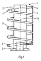
図1は、製品又はこれに類するものを螺旋状経路を介して垂直方向に搬送するように適合されたコンベアを表わす。実際に、このようなコンベアは、スパイラルコンベアやワインディングコンベアとして知られている。これらコンベアは、物品を搬送方向に向かって連続的な流れで搬送することができる。この製品の流れは、垂直方向に搬送するか、又は処理セクションに留める(buffer)ようにすることができる。これらコンベアは、例えば食品加工業、流通センター、グラフィック産業やこれらに類する領域で利用することができる。 FIG. 1 represents a conveyor adapted to transport a product or the like vertically through a spiral path. In fact, such conveyors are known as spiral conveyors and winding conveyors. These conveyors can convey articles in a continuous flow toward the conveyance direction. This product stream can be conveyed vertically or buffered in the processing section. These conveyors can be used in, for example, food processing industries, distribution centers, graphic industries, and similar areas.
図示のコンベアは、フレーム1を備えている。この場合には、前記フレームは、中心軸線2aを有する中央柱状体2と、脚部3と、中央柱状体2の周囲に延在し、該中央柱状体に固定された螺旋状の案内シュート4と備えている。様々な種類の他のフレーム構造を利用することもできる。エンドプーリ5,6が案内シュート4の上端及び下端に設けられており、フレーム1の復帰シュート7が螺旋状の案内シュート4の両端間に延在している。この場合には、無端コンベアベルト8は、フレーム1によって支持されており、搬送部分及び復帰部分においてもう1つの経路を通じて案内されている。しかしながら、搬送部分が案内シュート4の下側で戻るように案内されている場合もある。無端コンベアベルトは、駆動手段(図示しない)によって搬送方向に駆動される。
The illustrated conveyor includes a
図示の場合では、螺旋状の案内シュート4には4つの屈曲部が設けられている。しかしながら、この数は状況に応じて増減させることができる。本発明では、駆動上の問題を生じずに高効率で多数の屈曲部を通過するように無端コンベアベルト8を駆動させることができる。図示の実施例では、駆動モータは、コンベアの経路の端部に設けられたエンドプーリ、すなわちエンドプーリ5又は6に係合している。必要であれば、搬送経路の他の位置で補助的な駆動モータを利用することもできる。リニア式駆動装置が、無端コンベアベルト8のために利用される場合がある。コンベアは、上側のエンドプーリ5及び下側のエンドプーリ6で他のコンベアに結合されている場合がある。
In the illustrated case, the
図3は、コンベアのコンベアベルトの一部におけるキャリアプレートの平面図である。図4は、搬送方向に対して垂直な(図3の断面IV−IVに沿った)平面における断面図である。図3及び図4を参照すると、無端コンベアベルト8には、直接又は例えばサイドボーチェーン(side bow chain)のような無端接続部材を介して互いに可動に結合された、複数のキャリアプレートが設けられている。当該実施例では、各キャリアプレート9には、平坦な上側搬送面10が形成されている。キャリアプレート9は搬送経路内で近接して互いに結合されているので、物品は多数の隣り合うキャリアプレート9によって支持されている。キャリアプレート9は、中心軸線2aに関して略径方向に延在している長手方向に延在している細長要素である。
FIG. 3 is a plan view of the carrier plate in a part of the conveyor belt of the conveyor. 4 is a cross-sectional view in a plane perpendicular to the transport direction (along the cross section IV-IV in FIG. 3). Referring to FIGS. 3 and 4, the
図4は、2つのガイドローラ、すなわちガイドローラ11及び第2のガイドローラ11aを備えたキャリアプレート9の実施例を表わす。これらガイドローラは、中心軸線2aの径方向(X方向)において互いから離隔している。両ガイドローラ11,11aは、Y方向に延在する回転軸線12,12aを中心として回転可能である。本明細書では、Y方向は、上側搬送面に対して垂直に延在する方向として規定されているので、螺旋状経路の傾斜角度に依存して垂直方向に近づく。ガイドローラ11,11aの回転軸線12,12aの向きは、Y方向に限定される訳ではない。回転軸線12,12aがY方向に対して傾斜して延在している場合もある。例えば、両ガイドローラ11,11aには、搬送方向に対して垂直な平面内で互いに対角を有した回転軸線12,12aが設けられている場合がある。例えば搬送方向において見ると、回転軸線がV字状に方向付けられている場合がある。
FIG. 4 shows an embodiment of the
ガイドローラ11,11aは、ガイドローラ11,11aを滑らかに回転させるために、好ましくは転がり軸受によって、対応する回転軸13,13aに支承されている。
The
図4に表わす実施例では、ガイドローラ12,12aは、それぞれフレーム1に固定されたガイド14及び第2のガイド14aと協働する。当該実施例では、コンベア1の中央柱状体2は、図4に表わすキャリアプレート9の右側(X方向)に配置されている。このことは、ガイド14が中心軸線2aの径方向においてガイドローラ11を支持することができるので、コンベアが正常に動作している場合における主な径方向の力が図4に表わすガイドローラ11及びガイド14に作用することを意味する。図4では、キャリアプレート9にはガイドローラ11,11aが設けられており、これらガイドローラは、上側搬送面10に対して垂直な平面に関して鏡面対称であり、搬送方向に対して並列して配置されている。図示の実施例では、この平面は、自身の軸線方向においてキャリアプレート9の中心と交差している。第2のガイドローラ11aは、ガイドローラ11と相違するように構成され、且つキャリアプレートに取り付けられている。図4に表わすガイド14,14aは螺旋状経路に沿った溝状の形態であり、これら溝は互いに向き合っており、ガイドローラ11,11aを案内する。中心軸線2aに沿って見た場合には、ガイドローラ11aと中心軸線2aとの距離はガイドローラ11と中心軸線2aとの距離よりも大きいので、第2のガイド14aの直径はガイド14の直径よりも大きい。
In the embodiment shown in FIG. 4, the
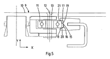
図5は、図4に表わす実施例の一部の拡大図である。ガイド14には、第1の案内面15及び第2の案内面16が形成されている。ガイドローラ11には、第1のガイドローラ面17及び第2のガイドローラ面18が形成されている。コンベアが動作している場合には、第1のガイドローラ表面17及び第1のガイド面15が第1の接触位置19で互いに接触しており、第2のガイドローラ面18及び第2のガイド面16が第2の接触位置20で互いに接触している。
FIG. 5 is an enlarged view of a part of the embodiment shown in FIG. A
当該実施例では、ガイドローラ11が円筒状であり、且つ、第1のガイド面15が搬送方向に対して垂直な平面内で回転軸線12に対して平行に延在しているので、第1の接触位置19では線接触している。線接触は数学用語であり、実際には線接触に近い状態であるにすぎないことに留意すべきである。
In this embodiment, the
本発明では、図5から理解されるように、第1の接触位置19における第1のガイドローラ面17に対する法線と、第2の接触位置における第2のガイドローラ面18に対する法線とは互いから逸れている。この特徴に起因して、ガイドローラ11はガイド14によって上方(Y方向)及び径方向(X方向)において支持されている。好ましくは、第2の接触位置20では点接触している。この第2の接触位置は第1の接触位置19に非常に近接しているので、第1の接触位置19及び第2の接触位置20におけるガイドローラ11の回転速度の差に起因する、ガイドローラ11とガイド14との滑りを最小限に抑えることができる。このことは、第2のガイド面16が好ましくは第1のガイド面15に隣接しており、ガイドローラ11が円筒状である場合には、第2の接触位置において点接触するために第1のガイド面15から回転軸線12に向かって下方に延在していることを意味する。点接触は数学用語であり、実際には点接触に近い状態であるにすぎないことに留意すべきである。
In the present invention, as understood from FIG. 5, the normal line to the first
図5の実施例では、ガイド14の断面は溝状(trough-shaped)である。この溝の開口部は、回転軸線12に対して径方向に向いており、螺旋状経路に沿って延在している。溝状のガイド14には、第2のガイド面16が前記開口部の下壁部として形成されており、第1のガイド面15が前記溝の底壁として形成されており、第3のガイド面21が前記溝の上壁部として形成されている。第3のガイド面21は、第2のガイド面16に対向して形成されており、キャリアプレート9がフレームに対して上方(Y方向)に持ち上がった場合に、ガイドローラ11をガイド14に沿って案内するように機能する。
In the embodiment of FIG. 5, the cross section of the
図6に表わすガイドローラ11及びガイド14から成る代替的な実施例では、ガイドローラ11はディアボロ状(diabolo shape)の形態である。このガイドローラ11は、例えばナイロンのようなプラスチック製のディアボロ状のカバー要素によって周囲を覆われた円筒状のローラから作られている。当該実施例では、ガイド14の一部は、ディアボロ状のガイドローラ11の周囲に設けられた溝に係止されており、その断面は矩形状である。好ましくは、溝に面したガイドの当該部分の角部が図6に表わすように丸められているので、過剰な局所的接触圧力を避けることができる。
In the alternative embodiment consisting of the
ガイド14には、第1のガイド面15及び第2のガイド面16が形成されている。当該実施例では、第2のガイド面16は、第2のガイドローラ面18において上方にディアボロ状のガイドローラ11を支持するように上方に面している。コンベアが動作している場合に、第1のガイドローラ面17及び第1のガイド面15が第1の接触位置19で互いに接触している。第1のガイドローラ面17が円筒状部分から成り、且つ、第1のガイド面15が搬送方向に対して垂直な平面内で回転軸線12に対して平行に延在しているので、第1の接触位置19では線接触している。第2のガイドローラ面18及び第2のガイド面16は、第2の接触位置20で互いに接触している。
A
第2のガイドローラ面18は、第1のガイドローラ面17に隣接しており、回転軸線12から見ると斜め上方に延在している。ディアボロ状のガイドローラの周囲に設けられた溝の開口部においては、その上壁が第2のガイドローラ面18によって形成されており、その底壁が回転軸線12に対して平行に延在するように第1のガイドローラ面17によって形成されており、その下壁が上壁に対向するように第3のガイドローラ面22によって形成されている。第3のガイドローラ面22は、コンベアが動作している際にキャリアプレートが上方に持ち上げられた場合に、ガイドローラをガイドに沿って案内するように機能する。
The second
図7は、キャリアプレート9の代替的な実施例を表わす。キャリアプレート9の長手方向長さが比較的短いので、実際にはキャリアプレートは単一のガイドローラ11を備えているにすぎない。この場合には、コンベアには、複数のキャリアプレート9が該コンベアの中心軸線2aの径方向において互いに隣接して配置されている。図7は、長手方向が搬送方向に対して略垂直に延在し、且つ上側搬送面10の平面に対して略平行に延在している3つのキャリアプレート9,9′,9″を(部分的に)表わす。第2のキャリアプレート9′には、第2のキャリアプレートのガイドローラ11′が設けられている。このガイドローラは、第2のキャリアプレートのガイド14′によって案内される。キャリアプレート9は、ガイド14によって支持されており、回転軸線12で効果的な支持位置を有している。当該実施例では、キャリアプレートは、第2の支持位置、この場合には端部分23を含んでいる。キャリアプレート9の端部分23は、回転軸線12から所定距離離隔して配置されている。第2のキャリアプレート9′には、支持位置、この場合には第2のキャリアプレートのガイドローラ11′の回転軸線の近傍に配置された第2のキャリアプレート9′の端部分24が形成されている。
FIG. 7 represents an alternative embodiment of the
第2のキャリアプレート9′の端部分24は、キャリアプレート9の端部分23と係合している。結果として、キャリアプレート9は、ガイドローラ11と、隣接する第2のキャリアプレート9′のガイドローラ11′との両方によって支持されている。端部分23,24は、上側搬送面10が略平坦となるような形状とされる。各端部分23,24での搬送方向におけるキャリアプレート9,9′両方の速度が略同一である場合には、隣接するキャリアプレート9,9′の間には摩擦力が生じない。以上より、本発明が、運転中にキャリアプレートとガイドとの間における抵抗を低くすることは明白である。第1の接触位置及第2の接触位置における第1のガイドローラ面及び第2のガイドローラ面に対する逸れた各法線によって、コンベアは高い駆動効率を実現することができる。
The
本発明は、上述の実施例に限定される訳ではないので、本発明の技術的範囲に属する多様な方法で変更することができる。例えば、キャリアプレートには、略垂直な回転軸線を有する第1のガイドローラと、キャリアプレートを上方にのみ支持するように搬送方向に対して垂直な水平回転軸を有しているもう一つのガイドローラとが設けられている場合がある。キャリアプレート及びガイドには、キャリアプレートが上方に移動することを防止する周知の要素が設けられている場合がある。キャリアプレートが1つのガイドローラを備え、キャリアプレートの第2の部分が滑動可能に支持されている場合がある。ディアボロ状のガイドローラを備えた代替的な実施例では、ガイドローラの第2のガイド面が、2つの同軸に配置されたフランジを備えたディアボロ状のガイドローラの代わりに、例えば円筒状のガイドローラと同軸に配置された唯一のフランジによって形成されている場合がある。第3の接触面が、キャリアプレートが上方に持ち上げられた場合に滑動可能に接触するように形成される場合がある。 The present invention is not limited to the above-described embodiments, and can be modified in various ways belonging to the technical scope of the present invention. For example, the carrier plate has a first guide roller having a substantially vertical rotation axis and another guide having a horizontal rotation axis perpendicular to the transport direction so as to support the carrier plate only upward. There may be a roller. The carrier plate and the guide may be provided with a known element that prevents the carrier plate from moving upward. The carrier plate may include one guide roller, and the second portion of the carrier plate may be slidably supported. In an alternative embodiment with a diabolo-shaped guide roller, the second guide surface of the guide roller replaces the diabolo-shaped guide roller with two coaxially arranged flanges, for example a cylindrical guide It may be formed by a single flange that is arranged coaxially with the roller. The third contact surface may be formed to slidably contact when the carrier plate is lifted upward.
1 フレーム
2 コンベア
2a 中心軸線
8 コンベアベルト
9 キャリアプレート
10 上側搬送面
11 ガイドローラ
11a 第2のガイドローラ
12 回転軸線
14 ガイド
14a 第2のガイド
15 第1のガイド面
16 第2のガイド面
17 第1のガイドローラ面
18 第2のガイドローラ面
19 第1の接触位置
20 第2の接触位置
22 第3のガイドローラ面
23 支持部分
24 支持部分
DESCRIPTION OF
Claims (14)
前記無端コンベアベルトは、互いに可動に接続され、且つ、それぞれが上側搬送面(10)を有した、キャリアプレート(9)を含んでおり、
前記フレームは、前記キャリアプレート(9)を前記螺旋状の経路に沿って案内するためにガイド(14)を少なくとも含んでおり、
少なくとも多数の前記キャリアプレート(9)は、前記上側搬送面(10)に対して垂直な方向に延在している要素を有した回転軸線(12)を中心として回転可能なガイドローラ(11)を少なくとも備えており、
前記ガイドローラ(11)は、第1の接触位置(19)で前記ガイド(14)の第1のガイド面(15)と接触している第1のガイドローラ面(17)と、第2の接触位置(20)で前記ガイド(14)に形成された第2のガイド面(16)と接触し、且つ、前記第1の接触位置(19)及び前記第2の接触位置(20)が互いに離隔している第2のガイドローラ面(18)と、を少なくとも有しており、
前記第1の接触位置(19)における前記第1のガイドローラ面(17)に対する法線は、前記第2の接触位置(20)における前記第2のガイドローラ面(18)に対する法線から逸れており、これにより前記ガイドローラが前記ガイドによって上方向及び径方向において支持されていることを特徴とするコンベア。 A conveyor for conveying a product or the like in a vertical direction through a spiral path centered on its own central axis (2a), which is movable along the spiral path; And the said conveyor provided with the flame | frame (1) which supports an endless conveyor belt (8) driven to a conveyance direction by a drive means,
The endless conveyor belt includes carrier plates (9) that are movably connected to each other and that each have an upper transport surface (10);
The frame includes at least a guide (14) for guiding the carrier plate (9) along the spiral path;
At least a large number of the carrier plates (9) are guide rollers (11) rotatable around a rotation axis (12) having elements extending in a direction perpendicular to the upper conveying surface (10). At least,
The guide roller (11) includes a first guide roller surface (17) that is in contact with the first guide surface (15) of the guide (14) at a first contact position (19), and a second guide roller (11). The contact position (20) is in contact with the second guide surface (16) formed on the guide (14), and the first contact position (19) and the second contact position (20) are in contact with each other. And at least a second guide roller surface (18) that is spaced apart,
The normal to the first guide roller surface (17) at the first contact position (19) deviates from the normal to the second guide roller surface (18) at the second contact position (20). Therefore, the guide roller is supported in the upward direction and the radial direction by the guide.
前記第1のガイド面(15)は、前記搬送方向に対して垂直な平面内で前記回転軸線(12)に対して平行に延在しており、
前記ガイドローラ(11)と前記ガイド(14)とが線接触していることを特徴とする請求項1〜5のいずれか一項に記載のコンベア。 The first guide roller surface (17) is formed by a cylindrical guide roller portion,
The first guide surface (15) extends in parallel to the rotation axis (12) in a plane perpendicular to the transport direction,
The conveyor according to any one of claims 1 to 5, wherein the guide roller (11) and the guide (14) are in line contact.
前記ガイド(14)は、前記搬送方向で見ると溝状の断面を有しており、
前記ガイド(14)は、前記溝状の断面の開口部が前記回転軸線(12)の径方向において前記ガイドローラ(11)を受容するように向いており、
前記溝状の断面の前記開口部の下壁は、前記第2のガイド面(16)であり、その底壁は、前記第1のガイド面(15)であり、その上壁は、前記下壁に対向し且つ第3のガイド面であり、
前記第3のガイド面は、前記コンベアの運転中に前記キャリアプレート(9)が前記回転軸線(12)に対して平行な方向において上方に持ち上げられた場合に、前記ガイドローラ(11)を前記ガイド(14)に沿って案内することを特徴とする請求項1〜7のいずれか一項記載のコンベア。 The guide roller (11) has a cylindrical shape,
The guide (14) has a groove-like cross section when viewed in the transport direction,
The guide (14) is oriented so that the opening of the groove-shaped cross section receives the guide roller (11) in the radial direction of the rotation axis (12),
The lower wall of the opening in the groove-shaped cross section is the second guide surface (16), the bottom wall is the first guide surface (15), and the upper wall is the lower wall. A third guide surface facing the wall;
The third guide surface moves the guide roller (11) when the carrier plate (9) is lifted upward in a direction parallel to the rotation axis (12) during operation of the conveyor. The conveyor according to any one of claims 1 to 7, characterized by guiding along a guide (14).
前記フランジは、前記第2のガイドローラ面(18)が前記第1のガイドローラ面(17)に隣接し、且つ、前記回転軸線(12)から径方向に見た場合に斜め上方に延在しているように適合されていることを特徴とする請求項1〜6のいずれか一項に記載のコンベア。 The second guide roller surface (18) is formed by at least a flange disposed coaxially with the guide roller (11),
The flange extends obliquely upward when the second guide roller surface (18) is adjacent to the first guide roller surface (17) and viewed in the radial direction from the rotation axis (12). The conveyor according to any one of claims 1 to 6, characterized in that the conveyor is adapted.
前記溝は、前記第2のガイドローラ面(18)である上壁と、前記回転軸線(12)と同軸に延在し、前記第1のガイドローラ面(17)である円筒状の底壁と、前記上壁に対向して配置され、第3のガイドローラ面(22)である下壁とによって形成されており、
これにより、前記第3のガイドローラ面は、前記コンベアの動作中に前記キャリアプレート(9)が前記回転軸線(12)に対して平行な方向において上方に持ち上げられた場合に、前記ガイドローラ(11)を前記ガイド(14)に沿って案内することを特徴とする請求項9に記載のコンベア。 The guide roller (11) has a diabolo shape with a groove formed around it,
The groove has an upper wall which is the second guide roller surface (18) and a cylindrical bottom wall which extends coaxially with the rotation axis (12) and which is the first guide roller surface (17). And a lower wall that is disposed to face the upper wall and is the third guide roller surface (22),
Thereby, when the carrier plate (9) is lifted upward in a direction parallel to the rotation axis (12) during the operation of the conveyor, the third guide roller surface is 11. A conveyor according to claim 9, characterized in that 11) is guided along the guide (14).
前記第2のガイドローラ(11a)は、前記フレームに設けられた第2のガイド(14a)によって支持され、前記第2のガイドに沿って転動するように適合されていることを特徴とする請求項1〜10のいずれか一項に記載のコンベア。 The carrier plate (9) includes at least a second guide roller (11a) spaced from the guide roller (11) in the radial direction of the central axis (2a),
The second guide roller (11a) is supported by a second guide (14a) provided on the frame, and is adapted to roll along the second guide. The conveyor as described in any one of Claims 1-10.
前記上側搬送面(10)に対して垂直且つ前記搬送方向に対して平行な平面が、対称線を形成していることを特徴とする請求項11又は12に記載のコンベア。 The carrier plate has a mirror image symmetrical form,
The conveyor according to claim 11 or 12, characterized in that a plane perpendicular to the upper transport surface (10) and parallel to the transport direction forms a symmetric line.
前記キャリアプレート(9)は、前記ガイドローラ(11)の前記回転軸線(12)から離隔された支持部分を備えており、
前記コンベアは、前記中心軸線(2a)の径方向で見ると前記キャリアプレート(9)に隣接する第2のキャリアプレート(9′)を少なくとも含んでおり、
前記第2のキャリアプレート(9′)は、第2のキャリアプレートのガイド(14′)によって支持された第2のキャリアプレートのガイドローラ(11′)と、前記第2のキャリアプレートの前記ガイドローラ(11′)の回転軸線の近傍に配置された支持部分(24)とを少なくとも備えており、
前記支持部分(24)は、前記第2のキャリアプレートの前記ガイドローラ(11′)を介して前記キャリアプレート(9)の支持部分(23)を支持するように、前記キャリアプレート(9)の前記支持部分(23)と係合していることを特徴とする請求項1〜10のいずれか一項に記載のコンベア。 The carrier plate (9) includes a single guide roller (11),
The carrier plate (9) includes a support portion spaced from the rotation axis (12) of the guide roller (11),
The conveyor includes at least a second carrier plate (9 ′) adjacent to the carrier plate (9) when viewed in the radial direction of the central axis (2a),
The second carrier plate (9 ′) includes a second carrier plate guide roller (11 ′) supported by a second carrier plate guide (14 ′) and the second carrier plate guide. And at least a support portion (24) disposed in the vicinity of the rotation axis of the roller (11 ′),
The support portion (24) of the carrier plate (9) is adapted to support the support portion (23) of the carrier plate (9) via the guide roller (11 ') of the second carrier plate. 11. A conveyor according to any one of the preceding claims, wherein the conveyor is engaged with the support portion (23).
Applications Claiming Priority (2)
| Application Number | Priority Date | Filing Date | Title |
|---|---|---|---|
| EP06121202.3A EP1902978B1 (en) | 2006-09-25 | 2006-09-25 | Conveyor |
| PCT/EP2007/060091 WO2008037686A1 (en) | 2006-09-25 | 2007-09-24 | Conveyor |
Related Child Applications (1)
| Application Number | Title | Priority Date | Filing Date |
|---|---|---|---|
| JP2014196526A Division JP5955365B2 (en) | 2006-09-25 | 2014-09-26 | Conveyor |
Publications (2)
| Publication Number | Publication Date |
|---|---|
| JP2010504261A true JP2010504261A (en) | 2010-02-12 |
| JP2010504261A5 JP2010504261A5 (en) | 2010-11-04 |
Family
ID=37766635
Family Applications (2)
| Application Number | Title | Priority Date | Filing Date |
|---|---|---|---|
| JP2009528739A Pending JP2010504261A (en) | 2006-09-25 | 2007-09-24 | Conveyor |
| JP2014196526A Active JP5955365B2 (en) | 2006-09-25 | 2014-09-26 | Conveyor |
Family Applications After (1)
| Application Number | Title | Priority Date | Filing Date |
|---|---|---|---|
| JP2014196526A Active JP5955365B2 (en) | 2006-09-25 | 2014-09-26 | Conveyor |
Country Status (9)
| Country | Link |
|---|---|
| US (1) | US7963389B2 (en) |
| EP (2) | EP1902978B1 (en) |
| JP (2) | JP2010504261A (en) |
| KR (1) | KR101423940B1 (en) |
| CN (2) | CN102351090B (en) |
| AU (1) | AU2007302032B8 (en) |
| ES (2) | ES2425982T3 (en) |
| PL (2) | PL2287094T3 (en) |
| WO (1) | WO2008037686A1 (en) |
Cited By (1)
| Publication number | Priority date | Publication date | Assignee | Title |
|---|---|---|---|---|
| KR101770021B1 (en) * | 2015-04-09 | 2017-08-21 | 한국공항공사 | Passenger boarding bridge with the stepless gangway in tunnels |
Families Citing this family (19)
| Publication number | Priority date | Publication date | Assignee | Title |
|---|---|---|---|---|
| ITMI20072005A1 (en) * | 2007-10-17 | 2009-04-18 | Pneumelectric Automazione S R | "SPIRAL CONVEYOR WITH TRANSPORTATION CHAIN WITH RETURN PATH ALONG THE SAME TRAIL" |
| NL1035783C2 (en) | 2008-08-04 | 2010-02-05 | Jan Willem Takens | Buffer conveyor for transporting and buffering products. |
| NL2002100C (en) | 2008-10-15 | 2010-04-16 | Specialty Conveyor Bv | A buffer conveyor having parallel tracks. |
| NL2002878C2 (en) * | 2009-05-13 | 2010-11-18 | Ambaflex Internat B V | A conveyor having parallel conveyor members. |
| KR101530755B1 (en) * | 2009-05-27 | 2015-06-22 | 플란타곤 인터내셔널 에이비 | Conveying system, tower structure with conveying system, and method for conveying containers with a conveying system |
| CH704135A1 (en) | 2010-11-26 | 2012-05-31 | Ferag Ag | Funding for a conveyor and conveyor having such funding. |
| CH704136A1 (en) | 2010-11-26 | 2012-05-31 | Ferag Ag | Funding chain for funding for a conveyor. |
| MY172945A (en) * | 2011-05-10 | 2019-12-16 | Flexmove System M Sdn Bhd | A link for a conveyor chain, a conveyor chain made up of said links and a method of operation of said conveyor chain |
| CN103842269B (en) * | 2011-07-19 | 2015-11-25 | 特兰斯诺姆系统股份有限公司 | Bent belt conveyor and the chain for described conveyer |
| ES2535278T3 (en) * | 2012-03-27 | 2015-05-07 | Specialty Conveyor B.V. | Conveyor |
| NL2009781C2 (en) * | 2012-11-09 | 2014-05-12 | Ambaflex Internat B V | TRANSPORTER. |
| JP5547320B1 (en) * | 2013-03-19 | 2014-07-09 | 第一施設工業株式会社 | Transport device |
| CA2927790C (en) * | 2013-11-12 | 2018-05-01 | Transnorm System, Inc. | Slat for a conveyor |
| NL2012475B1 (en) * | 2014-03-19 | 2016-01-08 | Ambaflex Int B V | Transporter for transporting goods in height. |
| NL2014054B1 (en) | 2014-12-24 | 2016-10-12 | Ambaflex Int B V | Transporter. |
| US10201122B2 (en) | 2015-01-23 | 2019-02-12 | Kevin W. Higgins | Large-scale helical farming apparatus |
| EP4332027A1 (en) * | 2019-03-29 | 2024-03-06 | Specialty Conveyor B.V. | An accumulating conveyor |
| CN111532664A (en) * | 2020-05-30 | 2020-08-14 | 金倍励金属(苏州)有限公司 | Metal mesh belt clamping device |
| EP4186826B1 (en) * | 2021-11-25 | 2024-04-03 | Ambaflex International B.V. | A helical conveyor |
Citations (7)
| Publication number | Priority date | Publication date | Assignee | Title |
|---|---|---|---|---|
| GB2148827A (en) * | 1983-10-11 | 1985-06-05 | Santrade Ltd | Conveyor apparatus |
| JPH01261127A (en) * | 1988-04-13 | 1989-10-18 | Sumitomo Heavy Ind Ltd | Bucket elevator type continuous unloader |
| JPH01261106A (en) * | 1988-04-11 | 1989-10-18 | Uehara Jushi Kogyo Kk | Chain conveyor |
| JPH03256905A (en) * | 1990-03-05 | 1991-11-15 | Sony Corp | Guide mechanism for platen of parts feeder |
| JPH08104411A (en) * | 1994-10-04 | 1996-04-23 | Toyo Kanetsu Kk | Chain support device on slat conveyor |
| JP2003312828A (en) * | 2002-04-23 | 2003-11-06 | Nobuyuki Tsuboi | Guide rail for travel |
| JP2009517306A (en) * | 2005-11-30 | 2009-04-30 | レックスノード インダストリーズ, エルエルシー | Conveyor plate with integral roller |
Family Cites Families (25)
| Publication number | Priority date | Publication date | Assignee | Title |
|---|---|---|---|---|
| US1149647A (en) * | 1909-09-27 | 1915-08-10 | Stanley G Harwood | Portable parcel-carrier. |
| FR1050098A (en) * | 1951-02-23 | 1954-01-05 | Eickhoff Geb | Steel element belt conveyor |
| DE957374C (en) * | 1951-12-29 | 1957-01-31 | Gewerk Eisenhuette Westfalia | Rubber or steel link conveyor belt |
| DE969122C (en) * | 1952-06-07 | 1958-04-30 | Wilhelm Zenz | Endless conveyor |
| DE1014925B (en) * | 1954-11-04 | 1957-08-29 | Gewerk Eisenhuette Westfalia | Endless conveyor belt with horizontal rollers |
| DE1004101B (en) * | 1955-10-08 | 1957-03-07 | Oskar Noe | Roller attachment to steel link conveyor belts |
| US3857476A (en) * | 1973-01-29 | 1974-12-31 | Theodore Equipment Corp | Helical endless-belt mechanisms for fuel or empty distray transporting and lifting |
| GB2226289B (en) * | 1988-12-23 | 1992-04-29 | Lineal Thermotech Ltd | Improvements in conveyors |
| US5038925A (en) * | 1990-04-20 | 1991-08-13 | Psc Floturn, Inc. | Conveyor for transporting articles along a curved path |
| WO1994000370A1 (en) * | 1992-06-22 | 1994-01-06 | Zimmermann, Marino | Pallet-support rail and slide-in pallet-storage unit with pallet-support rails and pallet-conveyor track |
| JP3256905B2 (en) * | 1992-09-14 | 2002-02-18 | 株式会社ブリヂストン | Pipe conveyor |
| DE4324120A1 (en) * | 1993-07-19 | 1995-01-26 | Hauni Werke Koerber & Co Kg | Conveyor chain |
| GB9321728D0 (en) * | 1993-10-21 | 1993-12-15 | Gramac Mechanical Handling Lim | Improvements relating to conveyors |
| US5620084A (en) * | 1995-03-30 | 1997-04-15 | Jervis B. Webb Company | Chain propelled belt conveyor |
| US5553697A (en) * | 1995-06-15 | 1996-09-10 | Otis Elevator Company | Overlay for a passenger conveyor roller track |
| US5857559A (en) * | 1996-02-13 | 1999-01-12 | Mannesmann Dematic Rapistan Corp. | Sliding belt turn conveyor |
| JP3606708B2 (en) * | 1997-05-26 | 2005-01-05 | 信行 坪井 | Driving guide system |
| NL1006909C2 (en) * | 1997-09-02 | 1999-03-04 | Ambaflex B V | Transporter. |
| JP4498537B2 (en) * | 2000-04-20 | 2010-07-07 | ウダカエンジニアリング株式会社 | Spiral conveyor |
| US6394260B1 (en) * | 2000-07-17 | 2002-05-28 | Pflow Industries, Inc. | Conveyor system including roller-guided carriage assemblies |
| AT412965B (en) * | 2001-09-20 | 2005-09-26 | Innova Patent Gmbh | CONVEYOR |
| NL1018994C2 (en) * | 2001-09-20 | 2003-03-21 | Ambaflex Internat B V | Transporter. |
| JP2003099272A (en) * | 2001-09-20 | 2003-04-04 | Ricoh Co Ltd | Task switching system and method, dsp, and modem |
| DE502004001435D1 (en) * | 2004-10-30 | 2006-10-19 | Ewab Holding Ag | Workpiece carrier for a workpiece conveyor with a conveyor chain and a guideway |
| DE202004017986U1 (en) * | 2004-11-19 | 2006-02-09 | Storcon Gmbh | Spiral conveyor for conveying goods comprises a support wall feeding a conveying chain with transport lamellae and aligned perpendicular to the roller axis of the conveyor chain |
-
2006
- 2006-09-25 EP EP06121202.3A patent/EP1902978B1/en active Active
- 2006-09-25 ES ES10191576T patent/ES2425982T3/en active Active
- 2006-09-25 ES ES06121202T patent/ES2425366T3/en active Active
- 2006-09-25 EP EP10191576.7A patent/EP2287094B1/en active Active
- 2006-09-25 PL PL10191576T patent/PL2287094T3/en unknown
- 2006-09-25 PL PL06121202T patent/PL1902978T3/en unknown
-
2007
- 2007-09-24 KR KR1020097007790A patent/KR101423940B1/en active IP Right Grant
- 2007-09-24 CN CN201110188742.8A patent/CN102351090B/en active Active
- 2007-09-24 CN CNA2007800413267A patent/CN101535153A/en active Pending
- 2007-09-24 US US12/442,634 patent/US7963389B2/en active Active
- 2007-09-24 WO PCT/EP2007/060091 patent/WO2008037686A1/en active Application Filing
- 2007-09-24 JP JP2009528739A patent/JP2010504261A/en active Pending
- 2007-09-24 AU AU2007302032A patent/AU2007302032B8/en active Active
-
2014
- 2014-09-26 JP JP2014196526A patent/JP5955365B2/en active Active
Patent Citations (7)
| Publication number | Priority date | Publication date | Assignee | Title |
|---|---|---|---|---|
| GB2148827A (en) * | 1983-10-11 | 1985-06-05 | Santrade Ltd | Conveyor apparatus |
| JPH01261106A (en) * | 1988-04-11 | 1989-10-18 | Uehara Jushi Kogyo Kk | Chain conveyor |
| JPH01261127A (en) * | 1988-04-13 | 1989-10-18 | Sumitomo Heavy Ind Ltd | Bucket elevator type continuous unloader |
| JPH03256905A (en) * | 1990-03-05 | 1991-11-15 | Sony Corp | Guide mechanism for platen of parts feeder |
| JPH08104411A (en) * | 1994-10-04 | 1996-04-23 | Toyo Kanetsu Kk | Chain support device on slat conveyor |
| JP2003312828A (en) * | 2002-04-23 | 2003-11-06 | Nobuyuki Tsuboi | Guide rail for travel |
| JP2009517306A (en) * | 2005-11-30 | 2009-04-30 | レックスノード インダストリーズ, エルエルシー | Conveyor plate with integral roller |
Cited By (1)
| Publication number | Priority date | Publication date | Assignee | Title |
|---|---|---|---|---|
| KR101770021B1 (en) * | 2015-04-09 | 2017-08-21 | 한국공항공사 | Passenger boarding bridge with the stepless gangway in tunnels |
Also Published As
| Publication number | Publication date |
|---|---|
| AU2007302032B8 (en) | 2013-03-14 |
| PL1902978T3 (en) | 2013-11-29 |
| EP1902978B1 (en) | 2013-05-22 |
| US7963389B2 (en) | 2011-06-21 |
| JP5955365B2 (en) | 2016-07-20 |
| US20100089724A1 (en) | 2010-04-15 |
| WO2008037686A1 (en) | 2008-04-03 |
| AU2007302032B2 (en) | 2013-02-21 |
| KR101423940B1 (en) | 2014-07-29 |
| CN102351090B (en) | 2015-05-20 |
| CN102351090A (en) | 2012-02-15 |
| EP2287094A1 (en) | 2011-02-23 |
| KR20090084819A (en) | 2009-08-05 |
| ES2425366T3 (en) | 2013-10-15 |
| WO2008037686A8 (en) | 2008-09-25 |
| EP2287094B1 (en) | 2013-05-29 |
| JP2015027918A (en) | 2015-02-12 |
| ES2425982T3 (en) | 2013-10-18 |
| AU2007302032A1 (en) | 2008-04-03 |
| EP1902978A1 (en) | 2008-03-26 |
| PL2287094T3 (en) | 2013-11-29 |
| CN101535153A (en) | 2009-09-16 |
Similar Documents
| Publication | Publication Date | Title |
|---|---|---|
| JP5955365B2 (en) | Conveyor | |
| JP6564986B2 (en) | Transported material discharge device | |
| US8100254B2 (en) | Conveyor for conveying and buffering articles | |
| US20060225991A1 (en) | Unit for use in automatic container return systems | |
| US11365056B2 (en) | Conveying device | |
| US11332314B2 (en) | Conveyor belt assembly | |
| AU2012384446B2 (en) | Transport conveyor and transport facility | |
| JP2013124157A (en) | Lifting device | |
| US5038923A (en) | Mini-roller conveyor with variable pressure traction sleeve | |
| JP6868223B2 (en) | Curve conveyor | |
| US6685005B2 (en) | Skewed-roller belt drive for belt-driven roller conveyor | |
| NL2020605B1 (en) | Chain conveyor curve | |
| JP2005187142A (en) | Conveying direction converting apparatus and roller conveying system using it | |
| KR102425593B1 (en) | Vertical type product sorting device | |
| JP6902593B2 (en) | Sorting device | |
| JP2002501869A (en) | Conveyor | |
| JP2586878Y2 (en) | Conveyor | |
| JPH09240823A (en) | Conveying device | |
| KR100368228B1 (en) | Conveyor for Conveying Packages at Curves | |
| JP2018188291A (en) | Conveyor-to-conveyor transfer mechanism | |
| JPH10338329A (en) | Conveyer | |
| GB2146965A (en) | Elevating apparatus | |
| JP2000025945A (en) | Goods sorting device |
Legal Events
| Date | Code | Title | Description |
|---|---|---|---|
| A521 | Written amendment |
Free format text: JAPANESE INTERMEDIATE CODE: A523 Effective date: 20100913 |
|
| A621 | Written request for application examination |
Free format text: JAPANESE INTERMEDIATE CODE: A621 Effective date: 20100913 |
|
| A977 | Report on retrieval |
Free format text: JAPANESE INTERMEDIATE CODE: A971007 Effective date: 20120920 |
|
| A131 | Notification of reasons for refusal |
Free format text: JAPANESE INTERMEDIATE CODE: A131 Effective date: 20120925 |
|
| A521 | Written amendment |
Free format text: JAPANESE INTERMEDIATE CODE: A523 Effective date: 20121225 |
|
| A131 | Notification of reasons for refusal |
Free format text: JAPANESE INTERMEDIATE CODE: A131 Effective date: 20130416 |
|
| A601 | Written request for extension of time |
Free format text: JAPANESE INTERMEDIATE CODE: A601 Effective date: 20130710 |
|
| A602 | Written permission of extension of time |
Free format text: JAPANESE INTERMEDIATE CODE: A602 Effective date: 20130718 |
|
| A601 | Written request for extension of time |
Free format text: JAPANESE INTERMEDIATE CODE: A601 Effective date: 20130917 |
|
| A602 | Written permission of extension of time |
Free format text: JAPANESE INTERMEDIATE CODE: A602 Effective date: 20130925 |
|
| A521 | Written amendment |
Free format text: JAPANESE INTERMEDIATE CODE: A523 Effective date: 20131010 |
|
| A02 | Decision of refusal |
Free format text: JAPANESE INTERMEDIATE CODE: A02 Effective date: 20140527 |
|
| A521 | Written amendment |
Free format text: JAPANESE INTERMEDIATE CODE: A523 Effective date: 20140926 |
|
| A911 | Transfer to examiner for re-examination before appeal (zenchi) |
Free format text: JAPANESE INTERMEDIATE CODE: A911 Effective date: 20141003 |
|
| A912 | Re-examination (zenchi) completed and case transferred to appeal board |
Free format text: JAPANESE INTERMEDIATE CODE: A912 Effective date: 20141205 |