EP1902978B1 - Conveyor - Google Patents
Conveyor Download PDFInfo
- Publication number
- EP1902978B1 EP1902978B1 EP06121202.3A EP06121202A EP1902978B1 EP 1902978 B1 EP1902978 B1 EP 1902978B1 EP 06121202 A EP06121202 A EP 06121202A EP 1902978 B1 EP1902978 B1 EP 1902978B1
- Authority
- EP
- European Patent Office
- Prior art keywords
- guide
- guide roller
- axis
- rotation
- contact
- Prior art date
- Legal status (The legal status is an assumption and is not a legal conclusion. Google has not performed a legal analysis and makes no representation as to the accuracy of the status listed.)
- Active
Links
- 230000008901 benefit Effects 0.000 description 7
- 238000005096 rolling process Methods 0.000 description 4
- 238000004519 manufacturing process Methods 0.000 description 3
- 238000004804 winding Methods 0.000 description 3
- 239000004677 Nylon Substances 0.000 description 1
- 230000003139 buffering effect Effects 0.000 description 1
- 235000019504 cigarettes Nutrition 0.000 description 1
- 238000010276 construction Methods 0.000 description 1
- 230000003247 decreasing effect Effects 0.000 description 1
- 238000006073 displacement reaction Methods 0.000 description 1
- 238000009826 distribution Methods 0.000 description 1
- 238000000034 method Methods 0.000 description 1
- 229920001778 nylon Polymers 0.000 description 1
- 239000004033 plastic Substances 0.000 description 1
- 238000005728 strengthening Methods 0.000 description 1
Images


Classifications
-
- B—PERFORMING OPERATIONS; TRANSPORTING
- B65—CONVEYING; PACKING; STORING; HANDLING THIN OR FILAMENTARY MATERIAL
- B65G—TRANSPORT OR STORAGE DEVICES, e.g. CONVEYORS FOR LOADING OR TIPPING, SHOP CONVEYOR SYSTEMS OR PNEUMATIC TUBE CONVEYORS
- B65G17/00—Conveyors having an endless traction element, e.g. a chain, transmitting movement to a continuous or substantially-continuous load-carrying surface or to a series of individual load-carriers; Endless-chain conveyors in which the chains form the load-carrying surface
- B65G17/06—Conveyors having an endless traction element, e.g. a chain, transmitting movement to a continuous or substantially-continuous load-carrying surface or to a series of individual load-carriers; Endless-chain conveyors in which the chains form the load-carrying surface having a load-carrying surface formed by a series of interconnected, e.g. longitudinal, links, plates, or platforms
- B65G17/065—Conveyors having an endless traction element, e.g. a chain, transmitting movement to a continuous or substantially-continuous load-carrying surface or to a series of individual load-carriers; Endless-chain conveyors in which the chains form the load-carrying surface having a load-carrying surface formed by a series of interconnected, e.g. longitudinal, links, plates, or platforms the load carrying surface being formed by plates or platforms attached to a single traction element
- B65G17/066—Conveyors having an endless traction element, e.g. a chain, transmitting movement to a continuous or substantially-continuous load-carrying surface or to a series of individual load-carriers; Endless-chain conveyors in which the chains form the load-carrying surface having a load-carrying surface formed by a series of interconnected, e.g. longitudinal, links, plates, or platforms the load carrying surface being formed by plates or platforms attached to a single traction element specially adapted to follow a curved path
-
- B—PERFORMING OPERATIONS; TRANSPORTING
- B65—CONVEYING; PACKING; STORING; HANDLING THIN OR FILAMENTARY MATERIAL
- B65G—TRANSPORT OR STORAGE DEVICES, e.g. CONVEYORS FOR LOADING OR TIPPING, SHOP CONVEYOR SYSTEMS OR PNEUMATIC TUBE CONVEYORS
- B65G17/00—Conveyors having an endless traction element, e.g. a chain, transmitting movement to a continuous or substantially-continuous load-carrying surface or to a series of individual load-carriers; Endless-chain conveyors in which the chains form the load-carrying surface
- B65G17/06—Conveyors having an endless traction element, e.g. a chain, transmitting movement to a continuous or substantially-continuous load-carrying surface or to a series of individual load-carriers; Endless-chain conveyors in which the chains form the load-carrying surface having a load-carrying surface formed by a series of interconnected, e.g. longitudinal, links, plates, or platforms
-
- B—PERFORMING OPERATIONS; TRANSPORTING
- B65—CONVEYING; PACKING; STORING; HANDLING THIN OR FILAMENTARY MATERIAL
- B65G—TRANSPORT OR STORAGE DEVICES, e.g. CONVEYORS FOR LOADING OR TIPPING, SHOP CONVEYOR SYSTEMS OR PNEUMATIC TUBE CONVEYORS
- B65G21/00—Supporting or protective framework or housings for endless load-carriers or traction elements of belt or chain conveyors
- B65G21/16—Supporting or protective framework or housings for endless load-carriers or traction elements of belt or chain conveyors for conveyors having endless load-carriers movable in curved paths
- B65G21/18—Supporting or protective framework or housings for endless load-carriers or traction elements of belt or chain conveyors for conveyors having endless load-carriers movable in curved paths in three-dimensionally curved paths
-
- B—PERFORMING OPERATIONS; TRANSPORTING
- B65—CONVEYING; PACKING; STORING; HANDLING THIN OR FILAMENTARY MATERIAL
- B65G—TRANSPORT OR STORAGE DEVICES, e.g. CONVEYORS FOR LOADING OR TIPPING, SHOP CONVEYOR SYSTEMS OR PNEUMATIC TUBE CONVEYORS
- B65G21/00—Supporting or protective framework or housings for endless load-carriers or traction elements of belt or chain conveyors
- B65G21/20—Means incorporated in, or attached to, framework or housings for guiding load-carriers, traction elements or loads supported on moving surfaces
- B65G21/22—Rails or the like engaging sliding elements or rollers attached to load-carriers or traction elements
-
- B—PERFORMING OPERATIONS; TRANSPORTING
- B65—CONVEYING; PACKING; STORING; HANDLING THIN OR FILAMENTARY MATERIAL
- B65G—TRANSPORT OR STORAGE DEVICES, e.g. CONVEYORS FOR LOADING OR TIPPING, SHOP CONVEYOR SYSTEMS OR PNEUMATIC TUBE CONVEYORS
- B65G33/00—Screw or rotary spiral conveyors
- B65G33/24—Details
- B65G33/26—Screws
-
- B—PERFORMING OPERATIONS; TRANSPORTING
- B65—CONVEYING; PACKING; STORING; HANDLING THIN OR FILAMENTARY MATERIAL
- B65G—TRANSPORT OR STORAGE DEVICES, e.g. CONVEYORS FOR LOADING OR TIPPING, SHOP CONVEYOR SYSTEMS OR PNEUMATIC TUBE CONVEYORS
- B65G39/00—Rollers, e.g. drive rollers, or arrangements thereof incorporated in roller-ways or other types of mechanical conveyors
- B65G39/10—Arrangements of rollers
- B65G39/20—Arrangements of rollers attached to moving belts or chains
-
- B—PERFORMING OPERATIONS; TRANSPORTING
- B65—CONVEYING; PACKING; STORING; HANDLING THIN OR FILAMENTARY MATERIAL
- B65G—TRANSPORT OR STORAGE DEVICES, e.g. CONVEYORS FOR LOADING OR TIPPING, SHOP CONVEYOR SYSTEMS OR PNEUMATIC TUBE CONVEYORS
- B65G2207/00—Indexing codes relating to constructional details, configuration and additional features of a handling device, e.g. Conveyors
- B65G2207/24—Helical or spiral conveying path
Definitions
- the present invention relates to a conveyor for conveying piece goods or the like .
- Such a conveyor is known from EP 1 009 692 B1 .
- This prior art document discloses a conveyor provided with carrier plates comprising guide rollers which are guided by a guide having a vertical guide surface.
- the known arrangement of the guide and the guide roller has resulted in a reduction of frictional forces during movement of a carrier plate along the helical path.
- WO 03/024846 discloses a conveyor for conveying piece goods through a helical path in upright direction.
- the conveyor comprises a frame and an endless conveyor belt having a conveying part guided in the helical path and a return path.
- the conveyor belt includes substantially rigid support members movably coupled to each other and having an upper transport face.
- the support members are coupled to each other at their adjacent edges and are also interconnected at their radially outer edge by means of a strengthening element extending in the conveying direction.
- At least a number of support members is provided with at least a guide roller rotatable about a rotation axis and adapted to roll along a helical guide surface guiding the rollers in substantially radial direction.
- the guide rollers are positioned near the radially outer edge.
- US 5 429 227 is related to a chain conveyor for the transport of mass flows of cigarettes or other rod-shaped commodities which has a series of identical links which are articulately connected to each other by alternating vertical and horizontal chain pins.
- the upper portions of the vertical pins carry platforms having supporting surfaces for the commodities, and each vertical pin further carries roller followers serving to track vertically spaced-apart portions of a guide surface which can have one or more non-linear portions, such as convex portions.
- the leading and trailing portions of successive platforms are interdigitated in such a way that the supporting surfaces of neighboring platforms can be inclined relative to each other as well as that the supporting surfaces of neighboring platforms can turn relative to each other about the axes of the respective vertical pins.
- Portions of the horizontal pins can extend into a channel between the vertically spaced-apart portions of the guide surface.
- the conveyor according to the invention is characterized by the features of claim 1.
- the guide roller of the carrier plate is supported by the guide in two different directions; in practice being a direction parallel to the axis of rotation as well as perpendicular thereto.
- the displacement of the guide roller with respect to the guide can be effected by rolling of the guide roller along the guide with low or without slip. This results in a lower friction between the carrier plate and the guide during movement of the carrier plate along the guide, resulting in a high driving efficiency.
- the axis of rotation may extend substantially perpendicular to the transport face.
- the advantage of this orientation is that the guide roller may be positioned close to the transport face resulting in a compact construction height of a carrier plate.
- the normal to the first guide roller surface in the first contact location may be substantially perpendicular to the axis of rotation. This has the benefit of low friction between the first guide roller surface and the first guide surface within the first contact location since this feature results in a rolling movement only of the first guide roller surface on the first guide surface.
- the first contact location is positioned at the same location as or close to the second contact location in radial direction of the axis of rotation, because in that configuration the difference in rotational speed of the guide roller at the first and second contact locations is small or even zero. Hence, the slip of the guide roller with respect to the guide in the second contact location is minimized, resulting in further improved efficiency.
- the second guide and guide roller surfaces are adapted such that the second contact location substantially forms a point contact. This has the advantage that the slip within the second contact location due to a varying distance to the axis of rotation is minimized.
- the first guide roller surface may be formed by a cylindrically shaped guide roller portion, whereas the first guide surface may extend parallel to the axis of rotation in a plane perpendicular to the conveying direction, hence forming a line contact between the guide roller and the guide in the first contact location.
- a line contact has the advantage of a stable support of the guide to the guide roller in the direction of the axis of rotation and provides a low rolling resistance.
- the second guide surface may be adjacent to the first guide surface and extend obliquely downwards when viewed from the central axis to the axis of rotation.
- the guide roller may have a cylindrical shape and the guide may have a trough-shaped cross section as seen in the conveying direction, wherein the guide is oriented such that the opening of the trough-shaped cross section receives the guide roller in radial direction of the axis of rotation.
- a lower wall of the opening of the trough comprises the second guide surface
- the bottom of the trough comprises the first guide surface
- an upper wall of the trough opposite to the lower wall comprises a third guide surface for guiding the guide roller along the guide if the carrier plate is lifted upwardly when the conveyor is in operation.
- the second guide roller surface can be formed by at least a flange disposed coaxially with the guide roller which flange is adapted such that the second guide roller surface is adjacent to the first guide roller surface and extending obliquely upwardly when viewed in radial direction from the axis of rotation.
- a guide roller with flange can be manufactured relatively easily.
- the guide roller has a diabolo shape having a circumferential groove defined by an upper wall which comprises the second guide roller surface, a bottom wall extending coaxially with the axis of rotation which bottom wall comprises the first guide roller surface, and a lower wall opposite to the upper wall which comprises a third guide roller surface for guiding the guide roller along the guide if the carrier plate is lifted upwardly when the conveyor is in operation.
- the advantage of a diabolo-shaped guide roller is that the guide does not only support the guide roller in upward direction and radial direction thereof, but also downwardly when the carrier plate is lifted upwardly.
- the carrier plate may be provided with at least a second guide roller spaced from the guide roller in a radial direction of the central axis, which second guide roller is adapted to be supported by and to roll along a second guide on the frame. It is advantageous when the carrier plate is supported at more than one supporting location by guide rollers so as to eliminate any sliding contacts between the carrier plate and the guides.
- the second guide roller have identical dimensions as the guide roller, since this minimizes manufacturing costs.
- the carrier plate may be mirror symmetrical, wherein a plane perpendicular to the upper transport face and parallel to the conveying direction forms the line of symmetry.
- a symmetrical configuration facilitates the manufacturing process.
- Fig. 1 is a very schematic and general side view of an embodiment of a conveyor according to the invention.
- Fig. 2 is a plan view of the frame of the conveyor of Fig. 1 .
- Fig. 3 is a larger-scale plan view of the carrier plates of a small portion of the conveyor belt of the conveyor of Fig. 1 and 2 in the helical path.
- Fig. 4 is a larger-scale sectional view along the line IV-IV in Fig. 3 perpendicular to the upper transport face of the carrier plate.
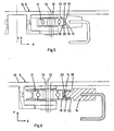
- Fig. 5 is an enlarged view of a part of Fig. 4 .
- Fig. 6 is a view corresponding to that of Fig. 5 showing an alternative embodiment of the guide roller and the guide.
- Fig. 1 shows a conveyor adapted to convey piece goods or the like, through a helical path in the vertical direction.
- conveyors are known as spiral conveyors or winding conveyors. These conveyors are able to transport articles in a continuous flow in a conveying direction. This product flow may be intended for vertical transport or for buffering in a process section. Areas of utilization are for example the food processing industry, distribution centers, the graphics industry and the like.
- the conveyor as shown comprises a frame 1, in this case including a central column 2 having a central axis 2a, feet 3 and a helical guide chute 4 extending around the column 2 and fixed thereto.
- a frame 1 in this case including a central column 2 having a central axis 2a, feet 3 and a helical guide chute 4 extending around the column 2 and fixed thereto.
- An end pulley 5, 6 is provided at the upper and lower ends of the guide chute 4, and between these ends of the helical guide chute 4 extends a return chute 7 of the frame 1.
- an endless conveyor belt 8 which is supported by the frame 1, is guided through another path in the conveying part and the return part.
- the conveyor belt is driven by driving means (not shown) in the conveying direction.
- the helical guide chute 4 includes four windings, but this number may be increased or decreased depending on the particular case. Due to the invention it is possible to drive the endless conveyor belt 8 through a great number of windings without any drive problems and at high efficiency.
- a drive motor may engage the end pulley at the end of the path of the conveyor, that is the end pulley 5 or 6, and if desired it is possible to use also auxiliary drives at other positions in the transport path.
- a linear drive for the endless conveyor belt 8 is also conceivable.
- the conveyor may join to other conveyors at the upper and lower end pulleys 5, 6.
- Fig. 3 shows a plan view of the carrier plates of a small portion of the conveyor belt of the conveyor.
- Fig. 4 shows a sectional view in a plane perpendicular to the conveying direction (along the line IV-IV in Fig. 3 ).
- the endless conveyor belt 8 comprises a plurality of carrier plates 9 movably coupled to each other, either directly or through an endless connecting member, such as a side bow chain.
- each carrier plate 9 has an upper flat transport face 10.
- the carrier plates 9 are joined to each other so closely in the transport path that articles may be supported by a number of adjacent carrier plates 9.
- Fig. 4 shows an embodiment of a carrier plate 9 which is provided with two guide rollers: a guide roller 11 and a second guide roller 11a, which are spaced from each other in radial direction of the central axis 2a (X direction).
- Both guide rollers 11, 11a are rotatable around an axis of rotation 12, 12a extending in the Y direction.
- the Y direction is herein defined as extending perpendicular to the upper transport face, which is close to vertical in practice, depending on the inclination angle of the helical path.
- the orientation of the axes of rotation 12, 12a of the guide rollers 11, 11a is not restricted to the Y direction.
- Axes of rotation 12, 12a extending obliquely with respect to the Y direction are also conceivable.
- both guide rollers 11, 11a comprise axes of rotation 12, 12a having opposite angles to each other in the plane perpendicular to the conveying direction, for example, a V-shaped axes orientation when viewed in the convey
- the guide rollers 11, 11a are journalled on corresponding rotary shafts 13, 13a, preferably by means of a rolling bearing to obtain smooth running of the guide rollers 11, 11a.
- the guide rollers 12 co-operate with a guide 14 and a second guide 14a, respectively, which are fixed to the frame 1.
- the central column 2 of the conveyor 1 is located at the right side (X direction) of the carrier plate 9 in Fig. 4 .
- This means that the main radial forces under normal operation of the conveyor are exerted on the guide roller 11 and the guide 14 in Fig. 4 , as guide 14 is able to support the guide roller 11 in a radial direction facing from the central axis 2a.
- the carrier plate 9 including the guide rollers 11, 11a are mirror symmetrical in a plane perpendicular to the upper transport face 10 and parallel to the conveying direction.
- this plane intersects the centre of the carrier plate 9 in axial direction thereof.
- the second guide roller 11a is designed and mounted to the carrier plate differently with respect to the guide roller 11.
- the guides 14 and 14a as shown in Fig. 4 comprise a groove shape along the helical path, which grooves face each other and guide the guide rollers 11, 11a.
- the second guide roller 11a has a larger distance from the central axis 2a than the guide roller 11, the second guide 14a has a larger diameter than the guide 14 when viewed along the central axis 2a.
- Fig. 5 shows an enlarged view of a part of the embodiment as shown in Fig. 4 .
- the guide 14 comprises a first guide surface 15 and a second guide surface 16.
- the guide roller 11 comprises a first guide roller surface 17 and a second guide roller surface 18.
- the first contact location 19 forms a line contact since the guide roller 11 is cylindrical and the first guide surface 15 extends parallel to the axis of rotation 12 in a plane perpendicular to the conveying direction in this embodiment. It is noted that a line contact is a mathematical term and in practice a line contact will only be approached.
- the normal to the first guide roller surface 17 in the first contact location 19 and the normal to the second guide roller surface 18 in the second contact location deviate from each other, which can be seen in Fig. 5 .
- the guide roller 11 can be supported upwardly (Y direction) and radially (X direction) by the guide 14.
- the second contact location 20 is preferably a point contact, which is located very close to the first contact location 19 so as to minimize slip between the guide roller 11 and the guide 14 due to differences in rotational speed of the guide roller 11 in the first and second contact locations 19, 20.
- the second guide surface 16 preferably is adjacent to the first guide surface 15 and extends downward as seen from the first guide surface 15 in the direction of the axis of rotation 12 in the case of a cylindrical guide roller 11 in order to create a point contact in the second contact location 20 in the case of a cylindrical roller 11. It is noted that a point contact is a mathematical term and in practice a point contact will only be approached.
- the guide 14 has a trough-shaped cross section.
- the opening of the trough is directed in radial direction to the axis of rotation 12 and extends along the helical path.
- the trough-shaped guide 14 comprises the second guide surface 16 as a lower wall of the opening, the first guide surface 15 as a bottom of the trough and a third guide surface 21 as an upper wall of the trough.
- the third guide surface 21 is opposite to the second guide surface 16 and serves to guide the guide roller 11 along the guide 14 if the carrier plate 9 is lifted upwardly (Y direction) with respect to the frame.
- the guide roller 11 has a diabolo shape.
- This guide roller 11 may be made of a cylindrical roller which is covered circumferentially by a diabolo-shaped cover element which is made of plastic such as nylon, for example.
- a portion of the guide 14 fitting into the circumferential groove of the diabolo-shaped guide roller 11 has a rectangular cross sectional shape.
- the corners of the this portion of the guide facing the groove have a rounded shape so as to avoid a too high local contact pressure, such as shown in Fig. 6 .
- the guide 14 comprises the first guide surface 15 and the second guide surface 16.
- the second guide surface 16 is facing upwardly so as to support the diabolo-shaped guide roller 11 upwardly in the second guide roller surface 18.
- the first contact location 19 forms a line contact since the first guide roller surface 17 forms a cylindrical portion and the first guide surface 15 extends parallel to the axis of rotation 12 in a plane perpendicular to the conveying direction.
- the second guide roller surface 18 and the second guide surface 16 are in contact with each other in a second contact location 20.
- the second guide roller surface 18 is adjacent to the first guide roller surface 17 and extends obliquely upwardly when viewed from the axis of rotation 12.
- the opening of the circumferential groove of the diabolo is defined by the second guide roller surface 18 as an upper wall, the first guide roller surface 17 as a bottom wall extending parallel to the axis of rotation 12, and a third guide roller surface 22 as a lower wall opposite to the upper wall.
- the third guide roller surface 22 serves for guiding the guide roller along the guide if the carrier plate is lifted upwardly when the conveyor is in operation.
- the invention provides a conveyor which is able to achieve a low resistance between the carrier plates and the guide during operation. Due to deviating normals to the first and second guide roller surfaces in the first and second contact locations, respectively, the conveyor provides a high driving efficiency.
- the carrier plate may comprise a first guide roller having a substantially vertical axis of rotation and another guide roller having a horizontal axis of rotation perpendicular to the conveying direction so as to support the carrier plate upwardly only.
- a carrier plate comprising one guide roller whereas a second part of the carrier plate is slidably supported is also conceivable.
- the second guide surface of the guide roller may be formed, for example, by only one flange which is disposed coaxially with the cylindrical guide roller instead of a diabolo-shape including two coaxial flanges.
Description
- The present invention relates to a conveyor for conveying piece goods or the like .
- Such a conveyor is known from
EP 1 009 692 B1 -
WO 03/024846 -
US 5 429 227 is related to a chain conveyor for the transport of mass flows of cigarettes or other rod-shaped commodities which has a series of identical links which are articulately connected to each other by alternating vertical and horizontal chain pins. The upper portions of the vertical pins carry platforms having supporting surfaces for the commodities, and each vertical pin further carries roller followers serving to track vertically spaced-apart portions of a guide surface which can have one or more non-linear portions, such as convex portions. The leading and trailing portions of successive platforms are interdigitated in such a way that the supporting surfaces of neighboring platforms can be inclined relative to each other as well as that the supporting surfaces of neighboring platforms can turn relative to each other about the axes of the respective vertical pins. Portions of the horizontal pins can extend into a channel between the vertically spaced-apart portions of the guide surface. - The conveyor of
US 5 429 227 corresponds to the preamble ofclaim 1. - It is an object of the present invention to provide an improved conveyor which operates at a still higher driving efficiency.
- To obtain this object, the conveyor according to the invention is characterized by the features of
claim 1. - Due to these features the guide roller of the carrier plate is supported by the guide in two different directions; in practice being a direction parallel to the axis of rotation as well as perpendicular thereto. As the guide roller is supported in both directions the displacement of the guide roller with respect to the guide can be effected by rolling of the guide roller along the guide with low or without slip. This results in a lower friction between the carrier plate and the guide during movement of the carrier plate along the guide, resulting in a high driving efficiency.
- The axis of rotation may extend substantially perpendicular to the transport face. The advantage of this orientation is that the guide roller may be positioned close to the transport face resulting in a compact construction height of a carrier plate.
- The normal to the first guide roller surface in the first contact location may be substantially perpendicular to the axis of rotation. This has the benefit of low friction between the first guide roller surface and the first guide surface within the first contact location since this feature results in a rolling movement only of the first guide roller surface on the first guide surface.
- In a preferred embodiment the first contact location is positioned at the same location as or close to the second contact location in radial direction of the axis of rotation, because in that configuration the difference in rotational speed of the guide roller at the first and second contact locations is small or even zero. Hence, the slip of the guide roller with respect to the guide in the second contact location is minimized, resulting in further improved efficiency.
- Preferably, the second guide and guide roller surfaces are adapted such that the second contact location substantially forms a point contact. This has the advantage that the slip within the second contact location due to a varying distance to the axis of rotation is minimized.
- The first guide roller surface may be formed by a cylindrically shaped guide roller portion, whereas the first guide surface may extend parallel to the axis of rotation in a plane perpendicular to the conveying direction, hence forming a line contact between the guide roller and the guide in the first contact location. A line contact has the advantage of a stable support of the guide to the guide roller in the direction of the axis of rotation and provides a low rolling resistance.
- The second guide surface may be adjacent to the first guide surface and extend obliquely downwards when viewed from the central axis to the axis of rotation. The advantage of this configuration is that a cylindrical guide roller can be applied without the risk of grating a side wall of the roller along the guide.
- The guide roller may have a cylindrical shape and the guide may have a trough-shaped cross section as seen in the conveying direction, wherein the guide is oriented such that the opening of the trough-shaped cross section receives the guide roller in radial direction of the axis of rotation. A lower wall of the opening of the trough comprises the second guide surface, the bottom of the trough comprises the first guide surface and an upper wall of the trough opposite to the lower wall comprises a third guide surface for guiding the guide roller along the guide if the carrier plate is lifted upwardly when the conveyor is in operation. The advantage of this configuration is that it is relatively simple to manufacture and provides a guide for guiding a guide roller both in upward and downward direction of the carrier plate.
- Alternatively, the second guide roller surface can be formed by at least a flange disposed coaxially with the guide roller which flange is adapted such that the second guide roller surface is adjacent to the first guide roller surface and extending obliquely upwardly when viewed in radial direction from the axis of rotation. Such a guide roller with flange can be manufactured relatively easily.
- Preferably, the guide roller has a diabolo shape having a circumferential groove defined by an upper wall which comprises the second guide roller surface, a bottom wall extending coaxially with the axis of rotation which bottom wall comprises the first guide roller surface, and a lower wall opposite to the upper wall which comprises a third guide roller surface for guiding the guide roller along the guide if the carrier plate is lifted upwardly when the conveyor is in operation. The advantage of a diabolo-shaped guide roller is that the guide does not only support the guide roller in upward direction and radial direction thereof, but also downwardly when the carrier plate is lifted upwardly.
- The carrier plate may be provided with at least a second guide roller spaced from the guide roller in a radial direction of the central axis, which second guide roller is adapted to be supported by and to roll along a second guide on the frame. It is advantageous when the carrier plate is supported at more than one supporting location by guide rollers so as to eliminate any sliding contacts between the carrier plate and the guides.
- Preferably, the second guide roller have identical dimensions as the guide roller, since this minimizes manufacturing costs.
- The carrier plate may be mirror symmetrical, wherein a plane perpendicular to the upper transport face and parallel to the conveying direction forms the line of symmetry. A symmetrical configuration facilitates the manufacturing process.
- The invention will hereafter be further explained with reference to the drawings showing embodiments of the conveyor according to the invention by way of example.
-
Fig. 1 is a very schematic and general side view of an embodiment of a conveyor according to the invention. -
Fig. 2 is a plan view of the frame of the conveyor ofFig. 1 . -
Fig. 3 is a larger-scale plan view of the carrier plates of a small portion of the conveyor belt of the conveyor ofFig. 1 and 2 in the helical path. -
Fig. 4 is a larger-scale sectional view along the line IV-IV inFig. 3 perpendicular to the upper transport face of the carrier plate. -
Fig. 5 is an enlarged view of a part ofFig. 4 . -
Fig. 6 is a view corresponding to that ofFig. 5 showing an alternative embodiment of the guide roller and the guide. -
Fig. 1 shows a conveyor adapted to convey piece goods or the like, through a helical path in the vertical direction. In practice such conveyors are known as spiral conveyors or winding conveyors. These conveyors are able to transport articles in a continuous flow in a conveying direction. This product flow may be intended for vertical transport or for buffering in a process section. Areas of utilization are for example the food processing industry, distribution centers, the graphics industry and the like. - The conveyor as shown comprises a
frame 1, in this case including acentral column 2 having acentral axis 2a,feet 3 and ahelical guide chute 4 extending around thecolumn 2 and fixed thereto. Of course various kinds of other frame structures are also conceivable. Anend pulley guide chute 4, and between these ends of thehelical guide chute 4 extends areturn chute 7 of theframe 1. In this case anendless conveyor belt 8, which is supported by theframe 1, is guided through another path in the conveying part and the return part. However, embodiments are conceivable in which the conveying part is guided back at the lower side of theguide chute 4. The conveyor belt is driven by driving means (not shown) in the conveying direction. - In the case as shown, the
helical guide chute 4 includes four windings, but this number may be increased or decreased depending on the particular case. Due to the invention it is possible to drive theendless conveyor belt 8 through a great number of windings without any drive problems and at high efficiency. In the embodiment shown a drive motor may engage the end pulley at the end of the path of the conveyor, that is theend pulley endless conveyor belt 8 is also conceivable. The conveyor may join to other conveyors at the upper and lower end pulleys 5, 6. -
Fig. 3 shows a plan view of the carrier plates of a small portion of the conveyor belt of the conveyor.Fig. 4 shows a sectional view in a plane perpendicular to the conveying direction (along the line IV-IV inFig. 3 ). With reference to these figures, theendless conveyor belt 8 comprises a plurality ofcarrier plates 9 movably coupled to each other, either directly or through an endless connecting member, such as a side bow chain. In the embodiment eachcarrier plate 9 has an upperflat transport face 10. Thecarrier plates 9 are joined to each other so closely in the transport path that articles may be supported by a number ofadjacent carrier plates 9. -
Fig. 4 shows an embodiment of acarrier plate 9 which is provided with two guide rollers: aguide roller 11 and asecond guide roller 11a, which are spaced from each other in radial direction of thecentral axis 2a (X direction). Both guiderollers rotation rotation guide rollers rotation rollers rotation - The
guide rollers rotary shafts guide rollers - In the embodiment shown in
Fig. 4 theguide rollers 12 co-operate with aguide 14 and asecond guide 14a, respectively, which are fixed to theframe 1. In this case thecentral column 2 of theconveyor 1 is located at the right side (X direction) of thecarrier plate 9 inFig. 4 . This means that the main radial forces under normal operation of the conveyor are exerted on theguide roller 11 and theguide 14 inFig. 4 , asguide 14 is able to support theguide roller 11 in a radial direction facing from thecentral axis 2a. InFig. 4 thecarrier plate 9 including theguide rollers upper transport face 10 and parallel to the conveying direction. In the embodiment as shown, this plane intersects the centre of thecarrier plate 9 in axial direction thereof. It is also possible that thesecond guide roller 11a is designed and mounted to the carrier plate differently with respect to theguide roller 11. Theguides Fig. 4 comprise a groove shape along the helical path, which grooves face each other and guide theguide rollers second guide roller 11a has a larger distance from thecentral axis 2a than theguide roller 11, thesecond guide 14a has a larger diameter than theguide 14 when viewed along thecentral axis 2a. -
Fig. 5 shows an enlarged view of a part of the embodiment as shown inFig. 4 . Theguide 14 comprises afirst guide surface 15 and asecond guide surface 16. Theguide roller 11 comprises a firstguide roller surface 17 and a secondguide roller surface 18. When the conveyor is in operation the firstguide roller surface 17 and thefirst guide surface 15 are in contact with each other in afirst contact location 19, and the secondguide roller surface 18 and thesecond guide surface 16 are in contact with each other in asecond contact location 20. - The
first contact location 19 forms a line contact since theguide roller 11 is cylindrical and thefirst guide surface 15 extends parallel to the axis ofrotation 12 in a plane perpendicular to the conveying direction in this embodiment. It is noted that a line contact is a mathematical term and in practice a line contact will only be approached. - According to the invention the normal to the first
guide roller surface 17 in thefirst contact location 19 and the normal to the secondguide roller surface 18 in the second contact location deviate from each other, which can be seen inFig. 5 . Due to this feature theguide roller 11 can be supported upwardly (Y direction) and radially (X direction) by theguide 14. Thesecond contact location 20 is preferably a point contact, which is located very close to thefirst contact location 19 so as to minimize slip between theguide roller 11 and theguide 14 due to differences in rotational speed of theguide roller 11 in the first andsecond contact locations second guide surface 16 preferably is adjacent to thefirst guide surface 15 and extends downward as seen from thefirst guide surface 15 in the direction of the axis ofrotation 12 in the case of acylindrical guide roller 11 in order to create a point contact in thesecond contact location 20 in the case of acylindrical roller 11. It is noted that a point contact is a mathematical term and in practice a point contact will only be approached. - In the embodiment of
Fig. 5 theguide 14 has a trough-shaped cross section. The opening of the trough is directed in radial direction to the axis ofrotation 12 and extends along the helical path. The trough-shapedguide 14 comprises thesecond guide surface 16 as a lower wall of the opening, thefirst guide surface 15 as a bottom of the trough and athird guide surface 21 as an upper wall of the trough. Thethird guide surface 21 is opposite to thesecond guide surface 16 and serves to guide theguide roller 11 along theguide 14 if thecarrier plate 9 is lifted upwardly (Y direction) with respect to the frame. - In the alternative embodiment of the
guide roller 11 and theguide 14 such as shown inFig. 6 theguide roller 11 has a diabolo shape. Thisguide roller 11 may be made of a cylindrical roller which is covered circumferentially by a diabolo-shaped cover element which is made of plastic such as nylon, for example. In this embodiment a portion of theguide 14 fitting into the circumferential groove of the diabolo-shapedguide roller 11 has a rectangular cross sectional shape. Preferably the corners of the this portion of the guide facing the groove have a rounded shape so as to avoid a too high local contact pressure, such as shown inFig. 6 . - The
guide 14 comprises thefirst guide surface 15 and thesecond guide surface 16. In this embodiment thesecond guide surface 16 is facing upwardly so as to support the diabolo-shapedguide roller 11 upwardly in the secondguide roller surface 18. When the conveyor is in operation the firstguide roller surface 17 and thefirst guide surface 15 are in contact with each other in thefirst contact location 19. Thefirst contact location 19 forms a line contact since the firstguide roller surface 17 forms a cylindrical portion and thefirst guide surface 15 extends parallel to the axis ofrotation 12 in a plane perpendicular to the conveying direction. The secondguide roller surface 18 and thesecond guide surface 16 are in contact with each other in asecond contact location 20. - The second
guide roller surface 18 is adjacent to the firstguide roller surface 17 and extends obliquely upwardly when viewed from the axis ofrotation 12. The opening of the circumferential groove of the diabolo is defined by the secondguide roller surface 18 as an upper wall, the firstguide roller surface 17 as a bottom wall extending parallel to the axis ofrotation 12, and a thirdguide roller surface 22 as a lower wall opposite to the upper wall. The thirdguide roller surface 22 serves for guiding the guide roller along the guide if the carrier plate is lifted upwardly when the conveyor is in operation. - From the foregoing it will be clear that the invention provides a conveyor which is able to achieve a low resistance between the carrier plates and the guide during operation. Due to deviating normals to the first and second guide roller surfaces in the first and second contact locations, respectively, the conveyor provides a high driving efficiency.
- The invention is not restricted to the above-described embodiments, which can be varied in a number of ways within the scope of the claims. For instance, the carrier plate may comprise a first guide roller having a substantially vertical axis of rotation and another guide roller having a horizontal axis of rotation perpendicular to the conveying direction so as to support the carrier plate upwardly only. A carrier plate comprising one guide roller whereas a second part of the carrier plate is slidably supported is also conceivable. Regarding the alternative embodiment with the diabolo-shaped guide roller the second guide surface of the guide roller may be formed, for example, by only one flange which is disposed coaxially with the cylindrical guide roller instead of a diabolo-shape including two coaxial flanges.
Claims (10)
- A conveyor for conveying piece goods or the like through a helical path around a central axis (2a) in a vertical direction, comprising a frame (1) which supports an endless conveyor belt (8) which is movable along a curved transport path and driven by driving means in a conveying direction, said conveyor belt (8) including carrier plates (9) which are movably connected to each other , each having an upper transport face (10), said frame including at least a guide (14) for guiding the carrier plates (9) along the helical path, wherein at least a number of carrier plates (9) comprise at least a guide roller (11) rotatable about an axis of rotation (12) having a component extending in a direction perpendicular to the transport face (10), said guide roller (11) having at least a first guide roller surface (17) which is in contact with a first guide surface (15) of the guide (14) in a first contact location (19) such that the guide roller (11) is radially supported by the guide (14), and a second guide roller surface (18) which is in contact with a second guide surface (16) on the guide (14) in a second contact location (20), which first and second contact locations (19, 20) are spaced from each other, wherein the normal to the first guide roller surface (17) in the first contact location (19) deviates from the normal to the second guide roller surface (18) in the second contact location (20) such that the guide roller (11) is also upwardly supported by the guide (14), characterized in that
the guide (14) has a third guide surface (21) opposite to the second guide surface (16) for guiding the guide roller (11) along the guide (14) if the carrier plate (9) is lifted upwardly with respect to the frame (1). - A conveyor according to claim 1, wherein the first contact location (19) is positioned at the same location as or close to the second contact location (20) in radial direction of the axis of rotation (12).
- A conveyor according to claim 1 or 2, wherein at least the second guide and guide roller surfaces (17, 18) are adapted such that the second contact location (20) substantially forms a point contact.
- A conveyor according to one of the preceding claims, wherein the first guide roller surface (17) is formed by a cylindrically shaped guide roller portion, whereas the first guide surface (15) extends parallel to the axis of rotation (12) in a plane perpendicular to the conveying direction, hence forming a line contact between the guide roller (11) and the guide (14).
- A conveyor according to claim 4, wherein the second guide surface (16) is adjacent to the first guide surface (15) extending obliquely downwards when viewed from the central axis (2a) to the axis of rotation (12).
- A conveyor according to one of the preceding claims, wherein the guide roller (11) has a cylindrical shape and the guide (14) has a trough-shaped cross section as seen in the conveying direction, wherein the guide (14) is oriented such that the opening of the trough-shaped cross section receives the guide roller (11) in radial direction of the axis of rotation (12), wherein a lower wall of the opening of the trough comprises said second guide surface (16), the bottom of the trough comprises the first guide surface (15) and an upper wall of the trough opposite to the lower wall comprises the third guide surface (21)
- A conveyor according to one of the preceding claims, wherein said carrier plate (9) is provided with at least a second guide roller (11a) spaced from the guide roller (11) in a radial direction of the central axis (2a), which second guide roller (11) is adapted to be supported by and to roll along a second guide (14a) on the frame.
- A conveyor according to claim 7, wherein the second guide roller (11a) has identical dimensions as the guide roller (11).
- A conveyor according to claim 7 or 8, wherein the carrier plate is mirror symmetrical, wherein a plane perpendicular to the upper transport face (10) and parallel to the conveying direction forms the line of symmetry.
- A conveyor according to one of the preceding claims, wherein the axis of rotation (12) extends substantially perpendicular to the transport face (10), and the normal to the first guide roller surface (17) in the first contact location (19) is substantially perpendicular to the axis of rotation (12).
Priority Applications (14)
| Application Number | Priority Date | Filing Date | Title |
|---|---|---|---|
| PL06121202T PL1902978T3 (en) | 2006-09-25 | 2006-09-25 | Conveyor |
| PL10191576T PL2287094T3 (en) | 2006-09-25 | 2006-09-25 | Conveyor with a curved transport path |
| EP06121202.3A EP1902978B1 (en) | 2006-09-25 | 2006-09-25 | Conveyor |
| ES10191576T ES2425982T3 (en) | 2006-09-25 | 2006-09-25 | Conveyor with curved trajectory |
| EP10191576.7A EP2287094B1 (en) | 2006-09-25 | 2006-09-25 | Conveyor with a curved transport path |
| ES06121202T ES2425366T3 (en) | 2006-09-25 | 2006-09-25 | Conveyor |
| CN201110188742.8A CN102351090B (en) | 2006-09-25 | 2007-09-24 | Conveyor |
| CNA2007800413267A CN101535153A (en) | 2006-09-25 | 2007-09-24 | Conveyor |
| KR1020097007790A KR101423940B1 (en) | 2006-09-25 | 2007-09-24 | Conveyor |
| JP2009528739A JP2010504261A (en) | 2006-09-25 | 2007-09-24 | Conveyor |
| US12/442,634 US7963389B2 (en) | 2006-09-25 | 2007-09-24 | Conveyor |
| PCT/EP2007/060091 WO2008037686A1 (en) | 2006-09-25 | 2007-09-24 | Conveyor |
| AU2007302032A AU2007302032B8 (en) | 2006-09-25 | 2007-09-24 | Conveyor |
| JP2014196526A JP5955365B2 (en) | 2006-09-25 | 2014-09-26 | Conveyor |
Applications Claiming Priority (1)
| Application Number | Priority Date | Filing Date | Title |
|---|---|---|---|
| EP06121202.3A EP1902978B1 (en) | 2006-09-25 | 2006-09-25 | Conveyor |
Related Child Applications (1)
| Application Number | Title | Priority Date | Filing Date |
|---|---|---|---|
| EP10191576.7 Division-Into | 2010-11-17 |
Publications (2)
| Publication Number | Publication Date |
|---|---|
| EP1902978A1 EP1902978A1 (en) | 2008-03-26 |
| EP1902978B1 true EP1902978B1 (en) | 2013-05-22 |
Family
ID=37766635
Family Applications (2)
| Application Number | Title | Priority Date | Filing Date |
|---|---|---|---|
| EP10191576.7A Active EP2287094B1 (en) | 2006-09-25 | 2006-09-25 | Conveyor with a curved transport path |
| EP06121202.3A Active EP1902978B1 (en) | 2006-09-25 | 2006-09-25 | Conveyor |
Family Applications Before (1)
| Application Number | Title | Priority Date | Filing Date |
|---|---|---|---|
| EP10191576.7A Active EP2287094B1 (en) | 2006-09-25 | 2006-09-25 | Conveyor with a curved transport path |
Country Status (9)
| Country | Link |
|---|---|
| US (1) | US7963389B2 (en) |
| EP (2) | EP2287094B1 (en) |
| JP (2) | JP2010504261A (en) |
| KR (1) | KR101423940B1 (en) |
| CN (2) | CN101535153A (en) |
| AU (1) | AU2007302032B8 (en) |
| ES (2) | ES2425366T3 (en) |
| PL (2) | PL1902978T3 (en) |
| WO (1) | WO2008037686A1 (en) |
Families Citing this family (20)
| Publication number | Priority date | Publication date | Assignee | Title |
|---|---|---|---|---|
| ITMI20072005A1 (en) * | 2007-10-17 | 2009-04-18 | Pneumelectric Automazione S R | "SPIRAL CONVEYOR WITH TRANSPORTATION CHAIN WITH RETURN PATH ALONG THE SAME TRAIL" |
| NL1035783C2 (en) | 2008-08-04 | 2010-02-05 | Jan Willem Takens | Buffer conveyor for transporting and buffering products. |
| NL2002100C (en) | 2008-10-15 | 2010-04-16 | Specialty Conveyor Bv | A buffer conveyor having parallel tracks. |
| NL2002878C2 (en) * | 2009-05-13 | 2010-11-18 | Ambaflex Internat B V | A conveyor having parallel conveyor members. |
| SG176605A1 (en) * | 2009-05-27 | 2012-01-30 | Plantagon Int Ab | Conveying system, tower structure with conveying system, and method for conveying containers with a conveying system |
| CH704136A1 (en) | 2010-11-26 | 2012-05-31 | Ferag Ag | Funding chain for funding for a conveyor. |
| CH704135A1 (en) | 2010-11-26 | 2012-05-31 | Ferag Ag | Funding for a conveyor and conveyor having such funding. |
| MY172945A (en) | 2011-05-10 | 2019-12-16 | Flexmove System M Sdn Bhd | A link for a conveyor chain, a conveyor chain made up of said links and a method of operation of said conveyor chain |
| CN103842269B (en) * | 2011-07-19 | 2015-11-25 | 特兰斯诺姆系统股份有限公司 | Bent belt conveyor and the chain for described conveyer |
| ES2535278T3 (en) * | 2012-03-27 | 2015-05-07 | Specialty Conveyor B.V. | Conveyor |
| NL2009781C2 (en) * | 2012-11-09 | 2014-05-12 | Ambaflex Internat B V | TRANSPORTER. |
| JP5547320B1 (en) * | 2013-03-19 | 2014-07-09 | 第一施設工業株式会社 | Transport device |
| CA2927790C (en) * | 2013-11-12 | 2018-05-01 | Transnorm System, Inc. | Slat for a conveyor |
| NL2012475B1 (en) | 2014-03-19 | 2016-01-08 | Ambaflex Int B V | Transporter for transporting goods in height. |
| NL2014054B1 (en) | 2014-12-24 | 2016-10-12 | Ambaflex Int B V | Transporter. |
| US10201122B2 (en) | 2015-01-23 | 2019-02-12 | Kevin W. Higgins | Large-scale helical farming apparatus |
| KR101770021B1 (en) * | 2015-04-09 | 2017-08-21 | 한국공항공사 | Passenger boarding bridge with the stepless gangway in tunnels |
| EP4332027A1 (en) * | 2019-03-29 | 2024-03-06 | Specialty Conveyor B.V. | An accumulating conveyor |
| CN111532664A (en) * | 2020-05-30 | 2020-08-14 | 金倍励金属(苏州)有限公司 | Metal mesh belt clamping device |
| EP4186826B1 (en) * | 2021-11-25 | 2024-04-03 | Ambaflex International B.V. | A helical conveyor |
Citations (8)
| Publication number | Priority date | Publication date | Assignee | Title |
|---|---|---|---|---|
| FR1050098A (en) * | 1951-02-23 | 1954-01-05 | Eickhoff Geb | Steel element belt conveyor |
| DE957374C (en) * | 1951-12-29 | 1957-01-31 | Gewerk Eisenhuette Westfalia | Rubber or steel link conveyor belt |
| DE1004101B (en) * | 1955-10-08 | 1957-03-07 | Oskar Noe | Roller attachment to steel link conveyor belts |
| DE1014925B (en) * | 1954-11-04 | 1957-08-29 | Gewerk Eisenhuette Westfalia | Endless conveyor belt with horizontal rollers |
| DE969122C (en) * | 1952-06-07 | 1958-04-30 | Wilhelm Zenz | Endless conveyor |
| GB2148827A (en) * | 1983-10-11 | 1985-06-05 | Santrade Ltd | Conveyor apparatus |
| US5429227A (en) * | 1993-07-19 | 1995-07-04 | Korber Ag | Chain conveyor |
| WO2007064659A1 (en) * | 2005-11-30 | 2007-06-07 | Rexnord Industries, Llc | Conveyor plate with integrated roller |
Family Cites Families (24)
| Publication number | Priority date | Publication date | Assignee | Title |
|---|---|---|---|---|
| US1149647A (en) * | 1909-09-27 | 1915-08-10 | Stanley G Harwood | Portable parcel-carrier. |
| US3857476A (en) * | 1973-01-29 | 1974-12-31 | Theodore Equipment Corp | Helical endless-belt mechanisms for fuel or empty distray transporting and lifting |
| JP2709600B2 (en) * | 1988-04-13 | 1998-02-04 | 住友重機械工業株式会社 | Bucket elevator continuous unloader |
| JPH01261106A (en) * | 1988-04-11 | 1989-10-18 | Uehara Jushi Kogyo Kk | Chain conveyor |
| GB2226289B (en) * | 1988-12-23 | 1992-04-29 | Lineal Thermotech Ltd | Improvements in conveyors |
| JPH03256905A (en) * | 1990-03-05 | 1991-11-15 | Sony Corp | Guide mechanism for platen of parts feeder |
| US5038925A (en) * | 1990-04-20 | 1991-08-13 | Psc Floturn, Inc. | Conveyor for transporting articles along a curved path |
| US5538384A (en) * | 1992-06-22 | 1996-07-23 | Marino Zimmermann | Pallet-support rail and slide-in pallet-storage unit with pallet-support rails and pallet-conveyor track |
| JP3256905B2 (en) * | 1992-09-14 | 2002-02-18 | 株式会社ブリヂストン | Pipe conveyor |
| GB9321728D0 (en) * | 1993-10-21 | 1993-12-15 | Gramac Mechanical Handling Lim | Improvements relating to conveyors |
| JPH08104411A (en) * | 1994-10-04 | 1996-04-23 | Toyo Kanetsu Kk | Chain support device on slat conveyor |
| US5620084A (en) * | 1995-03-30 | 1997-04-15 | Jervis B. Webb Company | Chain propelled belt conveyor |
| US5553697A (en) * | 1995-06-15 | 1996-09-10 | Otis Elevator Company | Overlay for a passenger conveyor roller track |
| US5857559A (en) * | 1996-02-13 | 1999-01-12 | Mannesmann Dematic Rapistan Corp. | Sliding belt turn conveyor |
| JP3606708B2 (en) * | 1997-05-26 | 2005-01-05 | 信行 坪井 | Driving guide system |
| NL1006909C2 (en) | 1997-09-02 | 1999-03-04 | Ambaflex B V | Transporter. |
| JP4498537B2 (en) * | 2000-04-20 | 2010-07-07 | ウダカエンジニアリング株式会社 | Spiral conveyor |
| US6394260B1 (en) * | 2000-07-17 | 2002-05-28 | Pflow Industries, Inc. | Conveyor system including roller-guided carriage assemblies |
| AT412965B (en) * | 2001-09-20 | 2005-09-26 | Innova Patent Gmbh | CONVEYOR |
| JP2003099272A (en) * | 2001-09-20 | 2003-04-04 | Ricoh Co Ltd | Task switching system and method, dsp, and modem |
| NL1018994C2 (en) * | 2001-09-20 | 2003-03-21 | Ambaflex Internat B V | Transporter. |
| JP2003312828A (en) * | 2002-04-23 | 2003-11-06 | Nobuyuki Tsuboi | Guide rail for travel |
| DE502004001435D1 (en) * | 2004-10-30 | 2006-10-19 | Ewab Holding Ag | Workpiece carrier for a workpiece conveyor with a conveyor chain and a guideway |
| DE202004017986U1 (en) * | 2004-11-19 | 2006-02-09 | Storcon Gmbh | Spiral conveyor for conveying goods comprises a support wall feeding a conveying chain with transport lamellae and aligned perpendicular to the roller axis of the conveyor chain |
-
2006
- 2006-09-25 PL PL06121202T patent/PL1902978T3/en unknown
- 2006-09-25 ES ES06121202T patent/ES2425366T3/en active Active
- 2006-09-25 EP EP10191576.7A patent/EP2287094B1/en active Active
- 2006-09-25 PL PL10191576T patent/PL2287094T3/en unknown
- 2006-09-25 EP EP06121202.3A patent/EP1902978B1/en active Active
- 2006-09-25 ES ES10191576T patent/ES2425982T3/en active Active
-
2007
- 2007-09-24 CN CNA2007800413267A patent/CN101535153A/en active Pending
- 2007-09-24 KR KR1020097007790A patent/KR101423940B1/en active IP Right Grant
- 2007-09-24 JP JP2009528739A patent/JP2010504261A/en active Pending
- 2007-09-24 CN CN201110188742.8A patent/CN102351090B/en active Active
- 2007-09-24 US US12/442,634 patent/US7963389B2/en active Active
- 2007-09-24 AU AU2007302032A patent/AU2007302032B8/en active Active
- 2007-09-24 WO PCT/EP2007/060091 patent/WO2008037686A1/en active Application Filing
-
2014
- 2014-09-26 JP JP2014196526A patent/JP5955365B2/en active Active
Patent Citations (8)
| Publication number | Priority date | Publication date | Assignee | Title |
|---|---|---|---|---|
| FR1050098A (en) * | 1951-02-23 | 1954-01-05 | Eickhoff Geb | Steel element belt conveyor |
| DE957374C (en) * | 1951-12-29 | 1957-01-31 | Gewerk Eisenhuette Westfalia | Rubber or steel link conveyor belt |
| DE969122C (en) * | 1952-06-07 | 1958-04-30 | Wilhelm Zenz | Endless conveyor |
| DE1014925B (en) * | 1954-11-04 | 1957-08-29 | Gewerk Eisenhuette Westfalia | Endless conveyor belt with horizontal rollers |
| DE1004101B (en) * | 1955-10-08 | 1957-03-07 | Oskar Noe | Roller attachment to steel link conveyor belts |
| GB2148827A (en) * | 1983-10-11 | 1985-06-05 | Santrade Ltd | Conveyor apparatus |
| US5429227A (en) * | 1993-07-19 | 1995-07-04 | Korber Ag | Chain conveyor |
| WO2007064659A1 (en) * | 2005-11-30 | 2007-06-07 | Rexnord Industries, Llc | Conveyor plate with integrated roller |
Also Published As
| Publication number | Publication date |
|---|---|
| CN102351090A (en) | 2012-02-15 |
| CN101535153A (en) | 2009-09-16 |
| EP2287094B1 (en) | 2013-05-29 |
| AU2007302032B8 (en) | 2013-03-14 |
| WO2008037686A8 (en) | 2008-09-25 |
| EP2287094A1 (en) | 2011-02-23 |
| AU2007302032B2 (en) | 2013-02-21 |
| US20100089724A1 (en) | 2010-04-15 |
| JP2010504261A (en) | 2010-02-12 |
| ES2425366T3 (en) | 2013-10-15 |
| WO2008037686A1 (en) | 2008-04-03 |
| PL1902978T3 (en) | 2013-11-29 |
| PL2287094T3 (en) | 2013-11-29 |
| CN102351090B (en) | 2015-05-20 |
| EP1902978A1 (en) | 2008-03-26 |
| ES2425982T3 (en) | 2013-10-18 |
| KR20090084819A (en) | 2009-08-05 |
| JP2015027918A (en) | 2015-02-12 |
| JP5955365B2 (en) | 2016-07-20 |
| US7963389B2 (en) | 2011-06-21 |
| AU2007302032A1 (en) | 2008-04-03 |
| KR101423940B1 (en) | 2014-07-29 |
Similar Documents
| Publication | Publication Date | Title |
|---|---|---|
| EP1902978B1 (en) | Conveyor | |
| CA2642513C (en) | Curved conveyor with guide for preventing radial belt migration | |
| EP1009692B1 (en) | Conveyor | |
| EP2074045B1 (en) | A conveyor for conveying and buffering articles | |
| NL2002878C2 (en) | A conveyor having parallel conveyor members. | |
| US20110180373A1 (en) | Buffer conveyor for conveying and buffering products | |
| EP3825261B1 (en) | A conveyor and a conveying system | |
| EP3715289B1 (en) | An accumulating conveyor | |
| WO2003024846A1 (en) | Conveyor | |
| EP4186826B1 (en) | A helical conveyor | |
| US11505409B2 (en) | Two-axis modular belt and conveyor |
Legal Events
| Date | Code | Title | Description |
|---|---|---|---|
| PUAI | Public reference made under article 153(3) epc to a published international application that has entered the european phase |
Free format text: ORIGINAL CODE: 0009012 |
|
| AK | Designated contracting states |
Kind code of ref document: A1 Designated state(s): AT BE BG CH CY CZ DE DK EE ES FI FR GB GR HU IE IS IT LI LT LU LV MC NL PL PT RO SE SI SK TR |
|
| AX | Request for extension of the european patent |
Extension state: AL BA HR MK YU |
|
| RIN1 | Information on inventor provided before grant (corrected) |
Inventor name: BALK, WOUTER Inventor name: HOPMAN, JOZEF WALTER MARIA Inventor name: BROERS, JOHANNES WILHELMUS |
|
| RIN1 | Information on inventor provided before grant (corrected) |
Inventor name: HOPMAN, JOZEF WALTER MARIA Inventor name: BALK, WOUTER Inventor name: BROERS, JOHANNES WILHELMUS |
|
| 17P | Request for examination filed |
Effective date: 20080926 |
|
| AKX | Designation fees paid |
Designated state(s): AT BE BG CH CY CZ DE DK EE ES FI FR GB GR HU IE IS IT LI LT LU LV MC NL PL PT RO SE SI SK TR |
|
| 17Q | First examination report despatched |
Effective date: 20081117 |
|
| GRAP | Despatch of communication of intention to grant a patent |
Free format text: ORIGINAL CODE: EPIDOSNIGR1 |
|
| GRAS | Grant fee paid |
Free format text: ORIGINAL CODE: EPIDOSNIGR3 |
|
| GRAJ | Information related to disapproval of communication of intention to grant by the applicant or resumption of examination proceedings by the epo deleted |
Free format text: ORIGINAL CODE: EPIDOSDIGR1 |
|
| R17C | First examination report despatched (corrected) |
Effective date: 20081117 |
|
| GRAP | Despatch of communication of intention to grant a patent |
Free format text: ORIGINAL CODE: EPIDOSNIGR1 |
|
| GRAS | Grant fee paid |
Free format text: ORIGINAL CODE: EPIDOSNIGR3 |
|
| GRAP | Despatch of communication of intention to grant a patent |
Free format text: ORIGINAL CODE: EPIDOSNIGR1 |
|
| GRAA | (expected) grant |
Free format text: ORIGINAL CODE: 0009210 |
|
| INTG | Intention to grant announced |
Effective date: 20130327 |
|
| AK | Designated contracting states |
Kind code of ref document: B1 Designated state(s): AT BE BG CH CY CZ DE DK EE ES FI FR GB GR HU IE IS IT LI LT LU LV MC NL PL PT RO SE SI SK TR |
|
| REG | Reference to a national code |
Ref country code: GB Ref legal event code: FG4D |
|
| RIN1 | Information on inventor provided before grant (corrected) |
Inventor name: BALK, WOUTER Inventor name: HOPMAN, JOZEF WALTER MARIA Inventor name: BROERS, JOHANNES WILHELMUS |
|
| REG | Reference to a national code |
Ref country code: CH Ref legal event code: EP |
|
| REG | Reference to a national code |
Ref country code: AT Ref legal event code: REF Ref document number: 613094 Country of ref document: AT Kind code of ref document: T Effective date: 20130615 |
|
| REG | Reference to a national code |
Ref country code: IE Ref legal event code: FG4D |
|
| REG | Reference to a national code |
Ref country code: DE Ref legal event code: R096 Ref document number: 602006036375 Country of ref document: DE Effective date: 20130718 |
|
| REG | Reference to a national code |
Ref country code: SE Ref legal event code: TRGR |
|
| REG | Reference to a national code |
Ref country code: NL Ref legal event code: T3 |
|
| REG | Reference to a national code |
Ref country code: ES Ref legal event code: FG2A Ref document number: 2425366 Country of ref document: ES Kind code of ref document: T3 Effective date: 20131015 |
|
| REG | Reference to a national code |
Ref country code: LT Ref legal event code: MG4D |
|
| PG25 | Lapsed in a contracting state [announced via postgrant information from national office to epo] |
Ref country code: SI Free format text: LAPSE BECAUSE OF FAILURE TO SUBMIT A TRANSLATION OF THE DESCRIPTION OR TO PAY THE FEE WITHIN THE PRESCRIBED TIME-LIMIT Effective date: 20130522 Ref country code: FI Free format text: LAPSE BECAUSE OF FAILURE TO SUBMIT A TRANSLATION OF THE DESCRIPTION OR TO PAY THE FEE WITHIN THE PRESCRIBED TIME-LIMIT Effective date: 20130522 Ref country code: IS Free format text: LAPSE BECAUSE OF FAILURE TO SUBMIT A TRANSLATION OF THE DESCRIPTION OR TO PAY THE FEE WITHIN THE PRESCRIBED TIME-LIMIT Effective date: 20130922 Ref country code: LT Free format text: LAPSE BECAUSE OF FAILURE TO SUBMIT A TRANSLATION OF THE DESCRIPTION OR TO PAY THE FEE WITHIN THE PRESCRIBED TIME-LIMIT Effective date: 20130522 Ref country code: GR Free format text: LAPSE BECAUSE OF FAILURE TO SUBMIT A TRANSLATION OF THE DESCRIPTION OR TO PAY THE FEE WITHIN THE PRESCRIBED TIME-LIMIT Effective date: 20130823 Ref country code: PT Free format text: LAPSE BECAUSE OF FAILURE TO SUBMIT A TRANSLATION OF THE DESCRIPTION OR TO PAY THE FEE WITHIN THE PRESCRIBED TIME-LIMIT Effective date: 20130923 |
|
| PG25 | Lapsed in a contracting state [announced via postgrant information from national office to epo] |
Ref country code: BG Free format text: LAPSE BECAUSE OF FAILURE TO SUBMIT A TRANSLATION OF THE DESCRIPTION OR TO PAY THE FEE WITHIN THE PRESCRIBED TIME-LIMIT Effective date: 20130822 |
|
| REG | Reference to a national code |
Ref country code: PL Ref legal event code: T3 |
|
| PG25 | Lapsed in a contracting state [announced via postgrant information from national office to epo] |
Ref country code: LV Free format text: LAPSE BECAUSE OF FAILURE TO SUBMIT A TRANSLATION OF THE DESCRIPTION OR TO PAY THE FEE WITHIN THE PRESCRIBED TIME-LIMIT Effective date: 20130522 |
|
| PG25 | Lapsed in a contracting state [announced via postgrant information from national office to epo] |
Ref country code: SK Free format text: LAPSE BECAUSE OF FAILURE TO SUBMIT A TRANSLATION OF THE DESCRIPTION OR TO PAY THE FEE WITHIN THE PRESCRIBED TIME-LIMIT Effective date: 20130522 Ref country code: EE Free format text: LAPSE BECAUSE OF FAILURE TO SUBMIT A TRANSLATION OF THE DESCRIPTION OR TO PAY THE FEE WITHIN THE PRESCRIBED TIME-LIMIT Effective date: 20130522 Ref country code: CZ Free format text: LAPSE BECAUSE OF FAILURE TO SUBMIT A TRANSLATION OF THE DESCRIPTION OR TO PAY THE FEE WITHIN THE PRESCRIBED TIME-LIMIT Effective date: 20130522 Ref country code: DK Free format text: LAPSE BECAUSE OF FAILURE TO SUBMIT A TRANSLATION OF THE DESCRIPTION OR TO PAY THE FEE WITHIN THE PRESCRIBED TIME-LIMIT Effective date: 20130522 |
|
| PG25 | Lapsed in a contracting state [announced via postgrant information from national office to epo] |
Ref country code: RO Free format text: LAPSE BECAUSE OF FAILURE TO SUBMIT A TRANSLATION OF THE DESCRIPTION OR TO PAY THE FEE WITHIN THE PRESCRIBED TIME-LIMIT Effective date: 20130522 |
|
| PLBE | No opposition filed within time limit |
Free format text: ORIGINAL CODE: 0009261 |
|
| STAA | Information on the status of an ep patent application or granted ep patent |
Free format text: STATUS: NO OPPOSITION FILED WITHIN TIME LIMIT |
|
| 26N | No opposition filed |
Effective date: 20140225 |
|
| PG25 | Lapsed in a contracting state [announced via postgrant information from national office to epo] |
Ref country code: MC Free format text: LAPSE BECAUSE OF FAILURE TO SUBMIT A TRANSLATION OF THE DESCRIPTION OR TO PAY THE FEE WITHIN THE PRESCRIBED TIME-LIMIT Effective date: 20130522 |
|
| REG | Reference to a national code |
Ref country code: CH Ref legal event code: PL |
|
| REG | Reference to a national code |
Ref country code: DE Ref legal event code: R097 Ref document number: 602006036375 Country of ref document: DE Effective date: 20140225 |
|
| REG | Reference to a national code |
Ref country code: IE Ref legal event code: MM4A |
|
| PG25 | Lapsed in a contracting state [announced via postgrant information from national office to epo] |
Ref country code: IE Free format text: LAPSE BECAUSE OF NON-PAYMENT OF DUE FEES Effective date: 20130925 Ref country code: CH Free format text: LAPSE BECAUSE OF NON-PAYMENT OF DUE FEES Effective date: 20130930 Ref country code: LI Free format text: LAPSE BECAUSE OF NON-PAYMENT OF DUE FEES Effective date: 20130930 |
|
| PG25 | Lapsed in a contracting state [announced via postgrant information from national office to epo] |
Ref country code: CY Free format text: LAPSE BECAUSE OF FAILURE TO SUBMIT A TRANSLATION OF THE DESCRIPTION OR TO PAY THE FEE WITHIN THE PRESCRIBED TIME-LIMIT Effective date: 20130522 Ref country code: TR Free format text: LAPSE BECAUSE OF FAILURE TO SUBMIT A TRANSLATION OF THE DESCRIPTION OR TO PAY THE FEE WITHIN THE PRESCRIBED TIME-LIMIT Effective date: 20130522 |
|
| PG25 | Lapsed in a contracting state [announced via postgrant information from national office to epo] |
Ref country code: LU Free format text: LAPSE BECAUSE OF NON-PAYMENT OF DUE FEES Effective date: 20130925 Ref country code: HU Free format text: LAPSE BECAUSE OF FAILURE TO SUBMIT A TRANSLATION OF THE DESCRIPTION OR TO PAY THE FEE WITHIN THE PRESCRIBED TIME-LIMIT; INVALID AB INITIO Effective date: 20060925 |
|
| REG | Reference to a national code |
Ref country code: FR Ref legal event code: PLFP Year of fee payment: 11 |
|
| REG | Reference to a national code |
Ref country code: FR Ref legal event code: PLFP Year of fee payment: 12 |
|
| REG | Reference to a national code |
Ref country code: FR Ref legal event code: PLFP Year of fee payment: 13 |
|
| PGFP | Annual fee paid to national office [announced via postgrant information from national office to epo] |
Ref country code: NL Payment date: 20230926 Year of fee payment: 18 Ref country code: IT Payment date: 20230921 Year of fee payment: 18 Ref country code: GB Payment date: 20230927 Year of fee payment: 18 Ref country code: AT Payment date: 20230901 Year of fee payment: 18 |
|
| PGFP | Annual fee paid to national office [announced via postgrant information from national office to epo] |
Ref country code: SE Payment date: 20230927 Year of fee payment: 18 Ref country code: PL Payment date: 20230901 Year of fee payment: 18 Ref country code: FR Payment date: 20230925 Year of fee payment: 18 Ref country code: DE Payment date: 20230927 Year of fee payment: 18 Ref country code: BE Payment date: 20230927 Year of fee payment: 18 |
|
| PGFP | Annual fee paid to national office [announced via postgrant information from national office to epo] |
Ref country code: ES Payment date: 20231002 Year of fee payment: 18 |