JP2010159543A - Aseismatic reinforcing structure - Google Patents
Aseismatic reinforcing structure Download PDFInfo
- Publication number
- JP2010159543A JP2010159543A JP2009000757A JP2009000757A JP2010159543A JP 2010159543 A JP2010159543 A JP 2010159543A JP 2009000757 A JP2009000757 A JP 2009000757A JP 2009000757 A JP2009000757 A JP 2009000757A JP 2010159543 A JP2010159543 A JP 2010159543A
- Authority
- JP
- Japan
- Prior art keywords
- existing
- small
- reinforcement
- pillar
- column
- Prior art date
- Legal status (The legal status is an assumption and is not a legal conclusion. Google has not performed a legal analysis and makes no representation as to the accuracy of the status listed.)
- Pending
Links
Images


Abstract
Description
本発明は、例えば既設の柱・梁を有する構築物、特にビルなどの建物の耐震補強構造に関する。 The present invention relates to a structure having existing pillars and beams, for example, an earthquake-proof reinforcement structure for a building such as a building.
従来たとえば耐震性能が劣る既設建物の耐震補強を行なう場合には、壁を増設したり、下記特許文献1のように既設柱の周囲を鋼板等の補強板で覆って強度を上げたり、下記特許文献2のように既設の柱と梁によって形成される開口部にブレースを入れて構造耐震指標Isが目標値以上となるように補強工事を行なっている。
Conventionally, for example, when performing seismic reinforcement of existing buildings with inferior seismic performance, increase the strength by increasing the wall by covering the existing pillars with a reinforcing plate such as a steel plate as in
しかし、補強工事を行なう建物は1981年以前に旧耐震基準により建設された建物で現在使用中の場合が多く、建物内部に壁を増設したり、柱の周囲を補強板で覆う作業は大掛かりで困難もしくは不可能であったり、可能であっても環境衛生や外観体裁等の観点から敬遠されることも少なくない。そこで、柱の内部にドリル等で長孔を穿孔し、その長孔内に剪断補強筋を所望量打設して柱を補強することも行なわれているが、穿孔作業は騒音・粉塵を伴う上に、既存の鉄筋と干渉する可能性があるため、使用中の建物では悪影響を及ぼすおそれが大きい。 However, there are many cases where buildings to be reinforced are built in accordance with the old earthquake resistance standards before 1981 and are currently in use, and it is a large-scale work to add walls to the inside of the building or cover the periphery of the pillars with reinforcing plates. Even if it is difficult or impossible, it is often avoided from the viewpoint of environmental sanitation and appearance. Therefore, a long hole is drilled inside the column with a drill or the like, and a desired amount of shear reinforcement is placed in the long hole to reinforce the column, but the drilling work involves noise and dust. In addition, it may interfere with existing rebars, so there is a great risk of adverse effects in buildings in use.
一方、ブレースを設置する場合には、いったん壁を取り壊して開口部を形成し、その開口部内に、工場等で予め製造した鉄骨ブレースを建て込む方法が一般的であるが、開口部にブレースが入るために外観及び内部からの景観が悪くなることは避けられない。また建物が鉄骨コンクリート造(SRC造)だった場合に、鉄骨ブレース建て込み工法では、鉄骨梁にアンカーを打設するだけのかぶり厚さが確保されていない場合があり、その場合には鉄骨ブレースをアンカーで固定することができない。 On the other hand, when installing a brace, a method is generally used in which a wall is once broken to form an opening, and a steel brace manufactured in advance in a factory or the like is built in the opening. It is inevitable that the appearance and the scenery from the inside will deteriorate to enter. In addition, when the building is a steel-concrete structure (SRC structure), the steel brace built-in method may not have enough cover thickness to place an anchor on the steel beam. Cannot be fixed with an anchor.
本発明は上記の問題点に鑑みて提案されたもので、建物内部に極力悪影響を及ぼすことなく、少ない作業量で、景観が悪くならない、穿孔作業が少なく、効果的な耐震補強を行なうことのできる耐震補強構造を提供することを目的とする。 The present invention has been proposed in view of the above-mentioned problems, and it is possible to perform effective seismic reinforcement without adversely affecting the inside of the building, with a small amount of work, with a small amount of work, with little perforation work. An object is to provide a seismic reinforcement structure that can be used.
上記の目的を達成するために本発明による耐震補強構造は、以下の構成としたものである。すなわち、上の既設梁と下の既設梁を上下方向に接続する形で位置する既設柱の側方に、該既設柱と連続してコンクリート製の小柱を形成すると共に、その小柱内に増設主筋を配筋し、その増設主筋のうちの少なくとも一部を、上下の既設梁内もしくはそれを越えて連続的に設けたことを特徴とする。 In order to achieve the above object, the seismic reinforcement structure according to the present invention has the following configuration. That is, a concrete small column is formed on the side of the existing column located in the vertical direction connecting the upper existing beam and the lower existing beam, and in the small column. The extension main bars are arranged, and at least a part of the extension main bars is continuously provided in or beyond the existing upper and lower beams.
上記小柱は、その少なくとも一部が上の既設梁と下の既設梁との間に位置するように構成するとよく、また上記小柱の少なくとも一部が、既設壁と一体に設けられるようにするとよい。さらに上記小柱内には、上記増設主筋と交差する方向の増設剪断補強筋を設けるとよく、又その増設剪断補強筋は、既設柱内と小柱内または小柱内と既設壁内に連続させて設けるとよい。また上記小柱は、既設柱を中にしてその両側に形成し、その両小柱と既設柱とを横方向に連結する増設剪断連結補強筋を設けるようにしてもよく、また上記既設柱と小柱の表面に連続して補強板を設け、その補強板を増設剪断補強筋を兼ねるアンカー筋で固定することもできる。 The small column may be configured such that at least a part thereof is positioned between the upper existing beam and the lower existing beam, and at least a part of the small column is provided integrally with the existing wall. Good. Further, it is preferable to provide an additional shear reinforcement bar in the direction crossing the main extension bar in the small column, and the extension shear reinforcement bar is continuous in the existing column and the small column or in the small column and the existing wall. It is good to provide it. Further, the small pillars may be formed on both sides with the existing pillars in between, and an additional shear connection reinforcing bar that connects both the small pillars and the existing pillars in the lateral direction may be provided. It is also possible to provide a reinforcing plate continuously on the surface of the small column, and fix the reinforcing plate with an anchor bar that also serves as an additional shear reinforcing bar.
本発明による耐震補強構造は上記の構成であるから以下のような作用効果が得られる。
(1)前記従来の鉄骨ブレースを用いる場合のように、ブレース設置用の開口部を形成するために既存建物の壁等を解体撤去する必要がない。従って、解体撤去に伴う作業手間、騒音、粉塵の発生を抑えられるのはもちろん、解体したガラやサッシ等の廃棄物の発生もない。
(2)鉄骨ブレースを用いた場合のように窓内にブレースの一部が露出して外観体裁を損ねることがない。
(3)小柱の増設主筋と必要に応じて設ける増設剪断補強筋のそれぞれの量または両者の量をバランスよく調整しながら、耐震補強を行なうことができる。
(4)既設躯体への穿孔作業は、増設主筋と増設剪断補強筋を配筋するために必要な最小限の個数と差し筋やアンカー筋等の施工に必要な深さだけに抑えることができる。即ち、前記公知の剪断補強筋を所望量打設して柱を補強する方法や鉄骨ブレース建て込み工法に比して、穿孔作業を少なくすることができる。
(5)柱の強度が強くなりすぎる場合には、その柱の縁に沿って、いわゆる壁スリットを形成することで強度バランスを保つことができる。
(6)鉄筋コンクリート造に限らず鉄骨コンクリート造などの建物や構造物の補強にも対応することができる。
Since the seismic reinforcement structure according to the present invention has the above-described configuration, the following effects can be obtained.
(1) Unlike the case of using the conventional steel brace, it is not necessary to dismantle and remove the walls of an existing building in order to form the opening for installing the brace. Therefore, it is possible to suppress the labor, noise and dust generation associated with the dismantling and removal, and there is no generation of waste such as dismantled waste and sash.
(2) A part of the brace is not exposed in the window as in the case of using a steel brace, and the appearance is not impaired.
(3) The seismic reinforcement can be performed while adjusting the amount of the main extension of the small column and the amount of the additional shear reinforcement provided as necessary or both in a well-balanced manner.
(4) Drilling work to the existing frame can be limited to the minimum number necessary to arrange the additional main reinforcement and the additional shear reinforcement and the depth required for the construction of the insertion bar, anchor bar, etc. . That is, drilling work can be reduced as compared with a method of reinforcing a column by placing a desired amount of the known shear reinforcement bars or a steel brace erection method.
(5) When the strength of the column becomes too strong, the strength balance can be maintained by forming a so-called wall slit along the edge of the column.
(6) It can respond to reinforcement of buildings and structures such as steel-reinforced concrete structures as well as reinforced concrete structures.
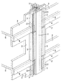
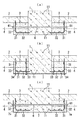
以下、本発明による耐震補強構造を図に示す実施形態に基づいて具体的に説明する。図1は本発明による耐震補強構造の一実施形態を示す補強途中の斜視図、図2(a)はその耐震補強構造の横断平面図、(b)はその正面図、(c)は(b)におけるc−c断面図、図3(a)は図2(a)の拡大図、(b)は更にその一部の拡大図、図4(a)は図2(c)の一部の拡大図、(b)は補強完了後の同上図、図5は補強完了後の前記c−c断面図、図6は補強完了後の斜視図である。 Hereinafter, the earthquake-proof reinforcement structure by this invention is demonstrated concretely based on embodiment shown in a figure. FIG. 1 is a perspective view in the middle of reinforcement showing an embodiment of the seismic reinforcement structure according to the present invention, FIG. 2 (a) is a transverse plan view of the seismic reinforcement structure, (b) is a front view thereof, and (c) is (b). ) In FIG. 3C, FIG. 3A is an enlarged view of FIG. 2A, FIG. 4B is an enlarged view of a part thereof, and FIG. 4A is a part of FIG. FIG. 5 is an enlarged view, FIG. 5 is a cross-sectional view taken along the line cc after completion of reinforcement, and FIG. 6 is a perspective view after completion of reinforcement.
本実施形態は、既設柱1の左右両側にそれぞれ既設壁2があり、その各既設壁2の外側の既設柱1の左右両側にそれぞれ小柱3を形成したもので、その各小柱3は既設柱1と連続的に形成され、それらの両小柱3,3および既設柱1の外側面は面一になるように形成されている。なお、上記小柱3は既設柱1の左右いずれか一方の側のみに形成するようにしてもよい。
In the present embodiment, there are existing
上記各小柱3は、その少なくとも一部が上下の既設梁4・4間に位置するように構成するとよく、図の実施形態は最下位の既設梁(地中梁)4の下側を除いて上下の既設梁4・4間に各小柱3の一部が位置し、最下位の既設梁4に対しては最下位の小柱3の下端全面が既設梁4に対面するように構成されている。図2(b)および(c)は建物の最下階を示すもので、各小柱3の下端はその端面の略全面が下側の最下位の既設梁(地中梁)4上に位置している。また上記各小柱3の上端は、その一部が上側の既設梁4の下側に位置し、それ以外は上層階に形成される小柱3と連続するように構成されている。その上層階の小柱3は、その上下端の一部が上下の既設梁4・4間に位置するように構成されている。
Each of the
また上記各小柱3内には、少なくとも各小柱3の長手方向とほぼ平行な方向すなわち上下方向に増設主筋31を配筋するもので、本実施形態においては、その増設主筋31と、それと交差する方向の増設剪断補強筋32とを配筋したものである。その増設主筋31として図示例は高強度ねじふし鉄筋を各小柱3内に複数本(図の場合は5本)配筋し、増設剪断補強筋32として既設柱1と既設壁2とに差し筋してモルタルで固定した横方向のモルタルアンカーを各小柱3内の上下方向に多数設けた構成である。なお、上記増設主筋31および増設剪断補強筋32の構成や材質および施工方法等は適宜変更可能であり、例えば上記の増設剪断補強筋32としてフープ筋等を用いることもできる。
Further, in each of the
さらに上記複数本の増設主筋31のうちの少なくとも一部は、ある階層の既設柱1に対して上下の既設梁4内もしくはそれを越えて上層階又は下層階へ連続的に設けるようにしたもので、図の場合は各小柱3内に配筋した5本の増設主筋31のうちの既設壁2側(図2(c)で左側)の2本の増設主筋31は既設梁4および既設スラブ5を貫通して、また既設壁2よりも外側(図2(c)で右側)の3本の増設主筋31は既設梁4および既設スラブ5を貫通することなく、建物の上下方向ほぼ全長にわたって連続的に設けたものである。また上記各増設主筋31の下端は、最下位の既設梁(地中梁)4内に挿通させ、上端は最上階の天井側の既設梁4および既設スラブ5に挿通させた構成である。
Furthermore, at least a part of the plurality of extension
上記各増設主筋31は、本実施形態においては所定長さの高強度ねじふし鉄筋を雌ねじ付きのカプラ等で順次接続した構成であるが、溶接等で接続してもよく、また小柱3の全長にわたって1本の鉄筋等で構成してもよい。また上記増設主筋31は、必ずしも既設梁4やスラブ5を貫通させる必要はなく、小柱3を既設柱1と連続させた状態で既設梁4やスラブ5と干渉しない位置において上下の既設梁4・4より上層及び下層へ連続するように増設主筋31を配置させることができれば、この増設主筋31を新設の主筋として既設柱1内の既設主筋11の増量とし、柱1のじん性を増大させることが可能である。
In the present embodiment, each of the extension
上記のように構成された耐震補強構造を施工するに際しては、例えば以下のようにすればよい。先ず、小柱3を増設すべき既設柱1の最も下側の既設梁(地中梁)4の上面に、増設主筋31を挿入するための縦孔をドリル等で所定の位置に複数個穿孔し、その各縦孔内に高強度ねじふし鉄筋等よりなる増設主筋31の下端を挿入嵌合して前記複数本の増設主筋31を立設する。またモルタルアンカー等よりなる増設剪断補強筋32を、既設柱1と既設壁2とに形成した横孔内に差し筋してモルタル等で固定することによって上下方向に多数設ける。その増設剪断補強筋32と増設主筋31とは必要に応じて線材等で互いに結束する。
When constructing the seismic reinforcement structure configured as described above, for example, the following may be performed. First, a plurality of vertical holes for inserting the additional
次いで、上記増設主筋31と増設剪断補強筋32とを囲むようにして型枠(不図示)や型枠を兼ねたプレートを配置し、その型枠内にコンクリートを流し込んで小柱3を形成すればよい。その小柱3は前述のように既設柱1の両側またはいずれか一方の側にのみに形成してもよく、両側に形成する場合には、その両側の小柱3を同時に形成するか、あるいは片方ずつ形成してもよい。また上記各小柱3は上下方向全長にわたって一括して同時に形成するか、1つの階ごと又は複数階ずつ形成してもよい。その際、増設主筋31を接続する必要がある場合には適時前記のようなカプラや溶接等で接続すればよい。図5および図6は上記のようにして既設壁2の外側であって既設柱1の両側に小柱3を形成した状態をあらわす。
Next, a formwork (not shown) or a plate that also serves as a formwork is disposed so as to surround the extension
上記のように本発明による耐震補強構造は、既設柱1の側方に、それと連続してコンクリート製の小柱3を形成すると共に、その小柱3内に増設主筋1を配筋し、その増設主筋のうちの少なくとも一部を、既設梁4内または/および既設スラブ5内もしくはそれを越えて連続的に設けるようにしたから、前記のようなブレース等を用いることなく、外観体裁のよい耐震補強を行うことができる。しかも、増設主筋31の本数を適宜調整し、また必要に応じて増設剪断補強筋32をも設けることで、必要かつ充分な耐震強度を有する耐震補強構造を容易・安価に提供することができる。
As described above, the seismic reinforcement structure according to the present invention forms the concrete
なお、上記小柱3は、前記図1〜図5の実施形態のように、その少なくとも一部が、上下の既設梁4・4間に位置するように構成するとよく、そのようにすると、既設柱1だけでなく、上記小柱3によっても上下方向の建物荷重等を支えることができる。また上記小柱3は、その少なくとも一部が、既設壁2と一体になるようにして設けるとよく、そのようにすると、小柱3と既設柱1および上下の既設梁4・4と既設壁2とがコンクリート等で直接もしくは増設主筋31や増設剪断補強筋32を介して連結させることができ、それらの相乗効果で剛性を高め、建物等の全体の耐震強度を増強することができる。なお、上記の補強によって柱周りの剛性が高くなりすぎる場合には、既設柱1と小柱3によって形成される新しい柱の縁に沿って、いわゆる壁スリットを形成することで強度バランスを良好に保つことができる。
The
また上記小柱3内には、増設主筋31だけでなく、前記図1〜図5の実施形態のように増設剪断補強筋32を設けると、上記小柱3の剪断強度さらには耐震強度を大幅に高めることができる。この場合、上記増設剪断補強筋32は増設主筋31に前述のような線材等で結束するとよく、そのようにすると、小柱3の剪断強度および耐震強度を更に増強することができる。また上記増設剪断補強筋32を、前記図1〜図5の実施形態のように既設柱1内と小柱3内に連続させて設けると、既設柱1と小柱3および建物等の全体強度を更に高めることができ、上記増設剪断補強筋32を、上記小柱3内と既設壁2内に連続させて設けると、小柱3と既設壁2および建物等の全体強度を更に高めることができる。
Further, if not only the additional main reinforcing
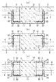
さらに上記の増設した小柱3と既設柱1とは、必要に応じて増設剪断連結補強筋や補強板等を用いて更に増強するようにしてもよい。図7(a)はその一例を示すもので、前記のように既設柱1と、その両側に形成した小柱3,3とを、横方向に貫通する増設剪断連結補強筋6で連結したもので、特に図の場合は上記の増設剪断連結補強筋6として高強度ねじふし鉄筋を用い、その両端部にねじ込んだナット61・61間に上記既設柱1と小柱3,3とを挟んで締め付け固定したものである。上記のように構成すると、既設柱1と小柱3,3とが更に強固に一体化されて、それらの強度ひいては建物等の全体強度を更に増大させることができる。
Furthermore, you may make it further reinforce the said
また図7(b)は既設柱1と小柱3,3の外面側に鋼板等よりなる補強板7を配置し、その補強板7を増設剪断補強筋を兼ねるアンカー筋33で固定したものである。そのアンカー筋33は、その一端側を、既設壁2に形成した横孔内に挿入してモルタル等で固定し、他端を上記補強板7に形成した不図示の貫通穴内に挿通して、その端部にナット34をねじ込み、そのナット34と小柱3との間に補強板7を挟んで固定した構成である。
FIG. 7B shows a structure in which a reinforcing
さらに図7(c)は上記小柱3,3の既設柱1と反対側の面をも補強板7で覆うように該補強板を平面コ字形に形成したもので、この場合も上記補強板7を、上記図7(b)に示すようなアンカー筋33等で固定するようにしてもよいが、本例においては図7(a)と同様の高強度ねじふし鉄筋よりなる増設剪断連結補強筋6で固定したものである。その増設剪断連結補強筋6は、既設柱1と小柱3,3および上記コ字形補強板7の対向片7a・7aを横方向に貫通するようにして配置され、その増設剪断連結補強筋6の両端部にねじ込んだナット61・61間に上記対向片7a・7aを介して既設柱1および小柱3,3を挟んで締め付け固定した構成である。
Further, FIG. 7 (c) shows that the reinforcing plate is formed in a plane U shape so that the surface opposite to the existing
なお、上記図7を含めて、これまでに説明した実施形態は、既設柱1の内外方向ほぼ中間部分に既設壁2がある場合を例示したが、例えば図8(a)〜(c)のように既設柱1の内側の面と連続して(面一に)既設壁2がある場合にも適用可能である。図8(a)は前記図1〜図6と同様に既設壁2の外側で既設柱1の左右両側に前記と同様に構成した小柱3を設けたものである。この場合にも必要に応じて前記図7(a)と同様の増設剪断連結補強筋6を設けるようにしてもよい。また図8(b)および(c)に示すように必要に応じて前記図7(b)および(c)と同様に補強板7等を設けることもできる。さらに前記図7(c)および図8(c)のようにコ字形の補強板7を用いる場合には、その補強板7を木製型枠等に替わる残留型枠として小柱3の打設形成前に設置した状態でコンクリート打設することができる。それによって、別途型枠を用いて設置したり脱型する等の作業が不要となり、工期の短縮を図りながら、廃材の低減、小柱3のコンクリートのひび割れ等を防止することもできる。さらに化粧仕上げ作業が容易となって美観にも優れる。
In addition, although embodiment described so far including the said FIG. 7 illustrated the case where the existing
また本発明は、例えば図9(a)に示すように既設柱1と小柱3の表面に連続してタイル貼り又は仕上げ塗装等を施すことも可能であり、それによって、より一層美観を高めることが出来る。さらに上記実施形態は、既設壁2の外面側に小柱3を設けた構成であり、それによって建物の外側からの作業で耐震補強工事が行なえるというメリットがあるが、本発明はこれに限定されるものではなく、例えば図9(b)に示すように小柱3を既設壁2の内面側に形成することも出来る。この場合には、建物の外側に作業用の足場を仮設しなくても、建物の内部で作業を行なうことによって耐震補強工事を行なうことが出来る。また例えば図9(c)に示すように、既設壁2が既設柱1の中央近傍に配置している場合には、小柱3を、既設壁2の内面側と外面側の両方に形成することも可能であり、上記いずれの場合にも増設主筋31や増設剪断補強筋32を前記と同様の要領で設けることによって、十分な強度を確保することができるものである。
In the present invention, for example, as shown in FIG. 9A, the surface of the existing
さらに本発明は鉄筋コンクリート造の建物等に限らず、例えば図10に示すような鉄骨コンクリート造の建物等にも適用可能である。図示例はコンクリート製の既設梁4内にH型鋼よりなる鉄骨41を有する鉄骨コンクリート造の建物に適用したもので、このような内部に鉄骨41を有する既設梁4内には、通常前記のような増設主筋31を配筋することはできないので、それを除く既設梁4や既設スラブ5内もしくはそれを越えて増設主筋31の少なくとも一部を配筋するようにしたものである。特に図の場合は各小柱3内に配筋される全ての増設主筋31の下端を、最も下側の既設梁(地中梁)4の中まで延長して配筋すると共に、各階の各小柱3内の既設壁2側の増設主筋31の下端は既設スラブ5内まで延長して配筋したものである。他の構成は前記実施形態と同様であり、同様の作用効果が得られる。
Further, the present invention is not limited to a reinforced concrete building or the like, and can be applied to a steel concrete building or the like as shown in FIG. The illustrated example is applied to a steel-concrete building having a steel frame 41 made of H-shaped steel in an existing
以上のように本発明による耐震補強構造は、上の既設梁と下の既設梁を上下方向に接続する形で位置する既設柱の側方に、該既設柱と連続してコンクリート製の小柱を形成すると共に、その小柱内に増設主筋を配筋し、その増設主筋のうちの少なくとも一部を、上下の既設梁内もしくはそれを越えて連続的に設けるようにしたから、前記のようなブレース等を用いることなく、外観体裁のよい耐震補強を行うことができる。しかも、増設主筋31の本数を適宜調整し、また必要に応じて増設剪断補強筋32をも設けることで、必要かつ充分な耐震強度を有する耐震補強構造を容易・安価に提供することが可能となる。従って、既設のビルなどの建築物や橋梁等の構築物におけるコンクリート躯体の耐震強度が不足する場合や、より信頼性の高い耐震補強を行いたい場合などにも好適に適用し、効果的な補強を行なうことができるものである。
As described above, the seismic retrofit structure according to the present invention is a concrete small column that is continuous with the existing column on the side of the existing column that is positioned in the form of connecting the upper existing beam and the lower existing beam in the vertical direction. As described above, the extension main bars are arranged in the small pillars, and at least a part of the extension main bars is continuously provided in or beyond the existing upper and lower beams. Seismic reinforcement with good appearance can be performed without using braces. Moreover, by appropriately adjusting the number of extension
1 既設柱
2 既設壁
3 小柱
31 増設主筋
32 増設剪断補強筋
33 アンカー筋
4 既設梁
5 既設スラブ
6 増設剪断連結補強筋
61 ナット
7 補強板
8 タイル
DESCRIPTION OF
Claims (8)
Priority Applications (1)
| Application Number | Priority Date | Filing Date | Title |
|---|---|---|---|
| JP2009000757A JP2010159543A (en) | 2009-01-06 | 2009-01-06 | Aseismatic reinforcing structure |
Applications Claiming Priority (1)
| Application Number | Priority Date | Filing Date | Title |
|---|---|---|---|
| JP2009000757A JP2010159543A (en) | 2009-01-06 | 2009-01-06 | Aseismatic reinforcing structure |
Publications (1)
| Publication Number | Publication Date |
|---|---|
| JP2010159543A true JP2010159543A (en) | 2010-07-22 |
Family
ID=42576908
Family Applications (1)
| Application Number | Title | Priority Date | Filing Date |
|---|---|---|---|
| JP2009000757A Pending JP2010159543A (en) | 2009-01-06 | 2009-01-06 | Aseismatic reinforcing structure |
Country Status (1)
| Country | Link |
|---|---|
| JP (1) | JP2010159543A (en) |
Cited By (7)
| Publication number | Priority date | Publication date | Assignee | Title |
|---|---|---|---|---|
| JP2012007418A (en) * | 2010-06-25 | 2012-01-12 | Eiji Makitani | Reinforcing structure of building and method for reinforcing building |
| JP2014047530A (en) * | 2012-08-31 | 2014-03-17 | Retorofit Japan | Reinforcement structure of concrete column |
| JP2015218561A (en) * | 2014-05-21 | 2015-12-07 | 株式会社竹中工務店 | Seismic strengthening structure and seismic strengthening method |
| JP6111369B1 (en) * | 2016-08-19 | 2017-04-05 | 株式会社ブルーム | Reinforced structure of reinforced concrete structure |
| JP2017106281A (en) * | 2015-12-11 | 2017-06-15 | 一般社団法人 レトロフィットジャパン協会 | Existing column reinforcement structure |
| JP2020084689A (en) * | 2018-11-29 | 2020-06-04 | 株式会社竹中工務店 | Earthquake strengthening structure |
| JP7127244B2 (en) | 2018-10-05 | 2022-08-30 | 株式会社竹中工務店 | Seismic reinforcement structure |
Citations (6)
| Publication number | Priority date | Publication date | Assignee | Title |
|---|---|---|---|---|
| JPH10196132A (en) * | 1997-01-14 | 1998-07-28 | Toda Constr Co Ltd | Earthquake resistant reinforcing structure of column with wall |
| JP2000045539A (en) * | 1999-08-19 | 2000-02-15 | Yahagi Construction Co Ltd | Reinforcing method for existing column in multi-story building |
| JP2001303773A (en) * | 2000-04-19 | 2001-10-31 | East Japan Railway Co | Reinforcing method for reinforced concrete column |
| JP2003227236A (en) * | 2001-11-29 | 2003-08-15 | Univ Of The Ryukyus | Permanent and emergent aseismatic reinforcement method for column with wall |
| JP2006274783A (en) * | 2005-03-04 | 2006-10-12 | Univ Of Ryukyus | Antiseismic reinforcing method for building adopting piloti frame |
| JP2007132131A (en) * | 2005-11-11 | 2007-05-31 | Taiheiyo Cement Corp | Reinforcing structure and reinforcing method for concrete building |
-
2009
- 2009-01-06 JP JP2009000757A patent/JP2010159543A/en active Pending
Patent Citations (6)
| Publication number | Priority date | Publication date | Assignee | Title |
|---|---|---|---|---|
| JPH10196132A (en) * | 1997-01-14 | 1998-07-28 | Toda Constr Co Ltd | Earthquake resistant reinforcing structure of column with wall |
| JP2000045539A (en) * | 1999-08-19 | 2000-02-15 | Yahagi Construction Co Ltd | Reinforcing method for existing column in multi-story building |
| JP2001303773A (en) * | 2000-04-19 | 2001-10-31 | East Japan Railway Co | Reinforcing method for reinforced concrete column |
| JP2003227236A (en) * | 2001-11-29 | 2003-08-15 | Univ Of The Ryukyus | Permanent and emergent aseismatic reinforcement method for column with wall |
| JP2006274783A (en) * | 2005-03-04 | 2006-10-12 | Univ Of Ryukyus | Antiseismic reinforcing method for building adopting piloti frame |
| JP2007132131A (en) * | 2005-11-11 | 2007-05-31 | Taiheiyo Cement Corp | Reinforcing structure and reinforcing method for concrete building |
Cited By (9)
| Publication number | Priority date | Publication date | Assignee | Title |
|---|---|---|---|---|
| JP2012007418A (en) * | 2010-06-25 | 2012-01-12 | Eiji Makitani | Reinforcing structure of building and method for reinforcing building |
| JP2014047530A (en) * | 2012-08-31 | 2014-03-17 | Retorofit Japan | Reinforcement structure of concrete column |
| JP2015218561A (en) * | 2014-05-21 | 2015-12-07 | 株式会社竹中工務店 | Seismic strengthening structure and seismic strengthening method |
| JP2017106281A (en) * | 2015-12-11 | 2017-06-15 | 一般社団法人 レトロフィットジャパン協会 | Existing column reinforcement structure |
| JP6111369B1 (en) * | 2016-08-19 | 2017-04-05 | 株式会社ブルーム | Reinforced structure of reinforced concrete structure |
| JP2018028248A (en) * | 2016-08-19 | 2018-02-22 | 株式会社ブルーム | Reinforcement structure of reinforced concrete structure |
| JP7127244B2 (en) | 2018-10-05 | 2022-08-30 | 株式会社竹中工務店 | Seismic reinforcement structure |
| JP2020084689A (en) * | 2018-11-29 | 2020-06-04 | 株式会社竹中工務店 | Earthquake strengthening structure |
| JP7062853B2 (en) | 2018-11-29 | 2022-05-09 | 株式会社竹中工務店 | Seismic retrofitting structure |
Similar Documents
| Publication | Publication Date | Title |
|---|---|---|
| KR101107300B1 (en) | Steel plate shear wall | |
| TWI438326B (en) | Semi - pre - cast flooring and its board construction method | |
| JP2010159543A (en) | Aseismatic reinforcing structure | |
| JP5213248B2 (en) | Seismic reinforcement structure for existing buildings | |
| UA82533C2 (en) | Building of large-span buildings with self-bracing made of pre-assembled bearing wall panels and floors | |
| JP2009249851A (en) | Seismic strengthening method for existing building | |
| JP2018520285A (en) | Prefabricated column and beam type construction | |
| JPH10131516A (en) | Reinforcing structure of existing building | |
| US10837167B2 (en) | Construction of the prefabricated column and beam type | |
| JP6543084B2 (en) | Structure | |
| CN110670720A (en) | Connecting structure of prefabricated column and superposed beam and construction method thereof | |
| JP5620462B2 (en) | Seismic reinforcement method for existing buildings | |
| KR20190036248A (en) | Seismic retrofit structure for building and seismic retrofit method using the same | |
| JP3999591B2 (en) | Seismic control structure of concrete structure with fiber reinforced cementitious material | |
| JP2007277856A (en) | Aseismatic reinforcing structure of existing building | |
| RU2233952C1 (en) | Multistorey building frame | |
| JP2009002079A (en) | Aseismatic reinforcing construction method for existing building | |
| JP6684088B2 (en) | Seismic retrofitting structure and method for existing buildings | |
| JP3909488B2 (en) | Seismic reinforcement structure of existing building and its construction method | |
| JP2004060310A (en) | Wooden earthquake-proof construction using earthquake-proof core | |
| JP6816941B2 (en) | Foundation structure of seismic isolated building | |
| JPH09273317A (en) | Vibration-resistant reinforcing method of existing concrete structure | |
| JP7435979B2 (en) | Earthquake reinforcement structure for existing buildings using CLT | |
| JP7442268B2 (en) | underground structure | |
| JP5658455B2 (en) | Unit building |
Legal Events
| Date | Code | Title | Description |
|---|---|---|---|
| A621 | Written request for application examination |
Free format text: JAPANESE INTERMEDIATE CODE: A621 Effective date: 20111116 |
|
| A977 | Report on retrieval |
Free format text: JAPANESE INTERMEDIATE CODE: A971007 Effective date: 20130214 |
|
| A131 | Notification of reasons for refusal |
Free format text: JAPANESE INTERMEDIATE CODE: A131 Effective date: 20130220 |
|
| A02 | Decision of refusal |
Free format text: JAPANESE INTERMEDIATE CODE: A02 Effective date: 20140312 |