JP2010101348A - 外筒取付構造 - Google Patents
外筒取付構造 Download PDFInfo
- Publication number
- JP2010101348A JP2010101348A JP2008271039A JP2008271039A JP2010101348A JP 2010101348 A JP2010101348 A JP 2010101348A JP 2008271039 A JP2008271039 A JP 2008271039A JP 2008271039 A JP2008271039 A JP 2008271039A JP 2010101348 A JP2010101348 A JP 2010101348A
- Authority
- JP
- Japan
- Prior art keywords
- outer cylinder
- mounting structure
- bearing box
- female screw
- cylinder mounting
- Prior art date
- Legal status (The legal status is an assumption and is not a legal conclusion. Google has not performed a legal analysis and makes no representation as to the accuracy of the status listed.)
- Granted
Links
- 230000002093 peripheral effect Effects 0.000 claims description 17
- 239000000314 lubricant Substances 0.000 claims description 8
- 238000000605 extraction Methods 0.000 claims description 7
- 230000000149 penetrating effect Effects 0.000 claims description 3
- 239000004519 grease Substances 0.000 description 14
- 238000004519 manufacturing process Methods 0.000 description 10
- 239000011295 pitch Substances 0.000 description 8
- 230000000694 effects Effects 0.000 description 6
- 239000003638 chemical reducing agent Substances 0.000 description 4
- 238000007789 sealing Methods 0.000 description 3
- 239000000470 constituent Substances 0.000 description 2
- 238000012423 maintenance Methods 0.000 description 2
- 230000013011 mating Effects 0.000 description 2
- 238000000034 method Methods 0.000 description 2
- 238000010008 shearing Methods 0.000 description 2
- 239000000853 adhesive Substances 0.000 description 1
- 230000001070 adhesive effect Effects 0.000 description 1
- 239000003795 chemical substances by application Substances 0.000 description 1
- 230000001771 impaired effect Effects 0.000 description 1
- 238000009434 installation Methods 0.000 description 1
- 238000003466 welding Methods 0.000 description 1
Images


Landscapes
- Mutual Connection Of Rods And Tubes (AREA)
- Gasket Seals (AREA)
- Transmission Devices (AREA)
Abstract
【解決手段】軸受111を介して回転軸131を保持する軸受箱110に回転軸131を同軸に内包する外筒120を密着固定する外筒取付構造において、軸受箱110のボス部112に外筒130が螺合し、ボス部112の端面側と外筒120の端部側に設けられた空間に弾性シール部材126が密着収容されていること。
【選択図】図3
Description
この周知の直線作動機500は、図6に示すように、回転駆動源530の出力軸に連結された回転軸531と、該回転軸531に螺合したナット532と、該ナット532に取り付けられた2本の直動部材533と、回転軸531とナット532と2本の直動部材533を内包する外筒520とを有している。
外筒620の軸方向中間部にはグリス等の潤滑剤を供給するための給脂口621が設けられ、該給脂口621は給脂口ボルト623により密封されている。
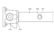
ボス部712に外筒720が螺合し、外筒720に固定ナット773が軸受箱710の端面714に当接して締め込まれることで軸受箱710に外筒720が密着固定される。
外筒720の軸方向中間部にはグリス等の潤滑剤を供給するための給脂口721が設けられ、該給脂口721は給脂口ボルト723により密封されている。
また、外筒620の中間部に設けた給脂口621の向く角方向を正確に特定したい場合、それぞれのフランジにおける複数の固定ボルト672の位置を正確に合わせてボルト穴加工する必要があり、さらに製造に時間とコストがかかるという問題があった。
また、外筒720の中間部に設けた給脂口721の向く角方向を正確に特定したい場合、組立時に給脂口721を正確な角方向に向けて固定した状態で固定ナット773を締め込む必要があり、組立に時間と手間がかかるとともに、締め込み時のバックラッシュや使用時の振動等によるネジの緩みで給脂口721の向く角方向が変化する虞があるという問題があった。
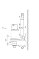
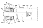
図1は、本発明の一実施例である外筒取付構造を備えた直線作動機の側面図であり、図2は、本発明の一実施例である外筒取付構造を備えた直線作動機の正面図であり、図3は、本発明の一実施例である外筒取付構造の断面説明図であり、図4は、図3の一部拡大図であり、図5は、図3の他の状態での一部拡大図である。
回転軸131には直動部材133の端部に固定されたナット132が螺合されており、回転軸131の正逆回転により直動部材133が往復動する。
モータ101および外筒120は、減速機102に対して平行に同一方向に延びるように設けられており、直線作動機100は全体として直動部材133の作動方向の全長が短くなっている。
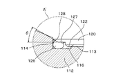
まず、軸受箱110の雄ネジ欠落部116にリング状の弾性シール部材126を装着した状態で外筒120の雌ネジ部122を軸受箱110のボス部112の雄ネジ部113に螺合する。
このとき、より密封性を高めるとともに固定後の緩みを防止するために、雌ネジ部122と雄ネジ部113に接着剤を適用しても良い。
なお、位置決めボルト125は外筒120とボス部112の相対回転を阻止するものであり強固に締結される必要はないため、ボルトではなくピン状の部材としても良い。
101 ・・・モータ
102 ・・・減速機
110、 610、710 ・・・軸受箱
111、511 ・・・軸受
112、 712 ・・・ボス部
113、 713 ・・・雄ネジ部
114、 714 ・・・端面
115 ・・・位置決め穴
116 ・・・雄ネジ欠落部
661 ・・・フランジ
120、520、620、720 ・・・外筒
121、521、621、721 ・・・給脂口
122、 722 ・・・雌ネジ部
123、523、623、723 ・・・給脂口ボルト
124 ・・・位置決め孔
125 ・・・位置決めボルト
126 ・・・弾性シール部材
127 ・・・雌ネジ欠落部
128 ・・・テーパ部
671 ・・・フランジ
672 ・・・固定ボルト
773 ・・・固定ナット
774 ・・・雄ネジ部
775 ・・・雌ネジ部
130、530 ・・・回転駆動源
131、531 ・・・回転軸
132、532 ・・・ナット
133、533 ・・・直動部材
Claims (5)
- 回転駆動源の出力取出部に設けられ軸受を介して回転軸を保持する軸受箱と、該軸受箱から前記回転駆動源の外方に延びる前記回転軸を同軸に内包する外筒とを密着固定する外筒取付構造において、
前記軸受箱が、外周面に前記外筒と螺合する雄ネジ部を有するボス部と、該ボス部の回転駆動源側に前記外筒の端部が突き当たる端面部を有し、
前記外筒が、一方の端部の内周面に前記軸受箱のボス部に螺合する雌ネジ部を有し、
前記軸受箱のボス部の端面側と前記外筒の端部側が、それぞれ雄ネジ欠落部と雌ネジ欠落部を有し、両欠落部により形成された空間に弾性シール部材が密着収容されていることを特徴とする外筒取付構造。 - 前記外筒が、雌ネジ部の少なくとも1か所に内周と外周とを貫通する位置決め孔を有し、
前記ボス部が、前記回転軸の軸線と直交する方向に位置決め穴を有していることを特徴とする請求項1に記載の外筒取付構造。 - 前記弾性シール部材が、前記雄ネジ部及び雌ネジ部のネジ山の1ピッチ以上の回転軸方向の厚みを有し、
前記雄ネジ欠落部と雌ネジ欠落部が、それぞれ前記雄ネジ部及び雌ネジ部のネジ山の1ピッチ以上の回転軸方向の長さを有していることを特徴とする請求項1または請求項2に記載の外筒取付構造。 - 前記雌ネジ欠落部が、前記外筒の端部に外周側に広がるテーパ部を有することを特徴とする請求項1乃至請求項3のいずれかに記載の外筒取付構造。
- 前記回転軸が、螺合されるナットを往復動させる送りネジ軸であり、
前記外筒が、他方の端部において前記ナットに接続された直動部材を軸方向に進退可能に支持するとともに、中間部に潤滑剤を供給する給脂口を有していることを特徴とする請求項1乃至請求項4のいずれかに記載の外筒取付構造。
Priority Applications (1)
| Application Number | Priority Date | Filing Date | Title |
|---|---|---|---|
| JP2008271039A JP4748612B2 (ja) | 2008-10-21 | 2008-10-21 | 外筒取付構造 |
Applications Claiming Priority (1)
| Application Number | Priority Date | Filing Date | Title |
|---|---|---|---|
| JP2008271039A JP4748612B2 (ja) | 2008-10-21 | 2008-10-21 | 外筒取付構造 |
Publications (2)
| Publication Number | Publication Date |
|---|---|
| JP2010101348A true JP2010101348A (ja) | 2010-05-06 |
| JP4748612B2 JP4748612B2 (ja) | 2011-08-17 |
Family
ID=42292177
Family Applications (1)
| Application Number | Title | Priority Date | Filing Date |
|---|---|---|---|
| JP2008271039A Active JP4748612B2 (ja) | 2008-10-21 | 2008-10-21 | 外筒取付構造 |
Country Status (1)
| Country | Link |
|---|---|
| JP (1) | JP4748612B2 (ja) |
Citations (5)
| Publication number | Priority date | Publication date | Assignee | Title |
|---|---|---|---|---|
| JPS5913182A (ja) * | 1982-06-03 | 1984-01-23 | ヨ−ゼフ・ガルトナ−・アンド・カンパニ− | 溶接不要の導管接合装置 |
| JPS6263452U (ja) * | 1985-10-11 | 1987-04-20 | ||
| JPS6338710A (ja) * | 1986-07-31 | 1988-02-19 | 太陽鉄工株式会社 | 2部材相互の連結装置 |
| JPH0828523A (ja) * | 1994-07-18 | 1996-02-02 | Nabco Ltd | 長尺油圧シリンダのロッド連結装置 |
| JP2005230287A (ja) * | 2004-02-19 | 2005-09-02 | Mizuno Corp | 長さ調節機構および長さ調節機構を装着した杖 |
-
2008
- 2008-10-21 JP JP2008271039A patent/JP4748612B2/ja active Active
Patent Citations (5)
| Publication number | Priority date | Publication date | Assignee | Title |
|---|---|---|---|---|
| JPS5913182A (ja) * | 1982-06-03 | 1984-01-23 | ヨ−ゼフ・ガルトナ−・アンド・カンパニ− | 溶接不要の導管接合装置 |
| JPS6263452U (ja) * | 1985-10-11 | 1987-04-20 | ||
| JPS6338710A (ja) * | 1986-07-31 | 1988-02-19 | 太陽鉄工株式会社 | 2部材相互の連結装置 |
| JPH0828523A (ja) * | 1994-07-18 | 1996-02-02 | Nabco Ltd | 長尺油圧シリンダのロッド連結装置 |
| JP2005230287A (ja) * | 2004-02-19 | 2005-09-02 | Mizuno Corp | 長さ調節機構および長さ調節機構を装着した杖 |
Also Published As
| Publication number | Publication date |
|---|---|
| JP4748612B2 (ja) | 2011-08-17 |
Similar Documents
| Publication | Publication Date | Title |
|---|---|---|
| KR102124471B1 (ko) | 파동기어장치 및 중공형 회전 액추에이터 | |
| CN202756390U (zh) | 锁紧螺母组件 | |
| CN202224665U (zh) | 机床的轴承预负载结构 | |
| JP3949123B2 (ja) | 航空機用モジュール取付装置 | |
| JP4748612B2 (ja) | 外筒取付構造 | |
| JP2010216610A (ja) | ロボットのシャフトに対するフランジ取付構造 | |
| JP2013122316A (ja) | ロック・リング及びねじ付きスタッド | |
| JP2016050597A (ja) | スタッドボルト及び部材結合構造 | |
| JP5763720B2 (ja) | 先端工具角度調整アダプタ | |
| JP2013224710A (ja) | モータと減速装置の連結構造 | |
| JP2017087374A (ja) | ロボットのハンド接続構造 | |
| JP2010043690A (ja) | 転がり軸受およびベアリングユニット | |
| WO2019088217A1 (ja) | インサートナット | |
| JP6088326B2 (ja) | スタッドボルト締め付け用ソケット | |
| JP2010019373A (ja) | 分割型シール環 | |
| JP3174891U (ja) | 電動リニアアクチュエータ | |
| EP2868940A2 (en) | Dowel element | |
| JP2012026495A (ja) | ドライブシャフトベアリングのハウジング装置 | |
| US10830332B2 (en) | Small-size reduction gearbox | |
| TWM450137U (zh) | 電動線性驅動器 | |
| US11512731B2 (en) | Bolt-nut | |
| US20090056485A1 (en) | Method of Connecting and Fixing Ball Screw Shaft to Motor Shaft | |
| KR20110005565U (ko) | 리드 스크류 어셈블리 | |
| JP6500759B2 (ja) | 圧入治具 | |
| TWI890921B (zh) | 諧波齒輪裝置 |
Legal Events
| Date | Code | Title | Description |
|---|---|---|---|
| A977 | Report on retrieval |
Free format text: JAPANESE INTERMEDIATE CODE: A971007 Effective date: 20101216 |
|
| A131 | Notification of reasons for refusal |
Free format text: JAPANESE INTERMEDIATE CODE: A131 Effective date: 20101221 |
|
| A521 | Written amendment |
Free format text: JAPANESE INTERMEDIATE CODE: A523 Effective date: 20110216 |
|
| TRDD | Decision of grant or rejection written | ||
| A01 | Written decision to grant a patent or to grant a registration (utility model) |
Free format text: JAPANESE INTERMEDIATE CODE: A01 Effective date: 20110511 |
|
| A01 | Written decision to grant a patent or to grant a registration (utility model) |
Free format text: JAPANESE INTERMEDIATE CODE: A01 |
|
| A61 | First payment of annual fees (during grant procedure) |
Free format text: JAPANESE INTERMEDIATE CODE: A61 Effective date: 20110511 |
|
| R150 | Certificate of patent or registration of utility model |
Ref document number: 4748612 Country of ref document: JP Free format text: JAPANESE INTERMEDIATE CODE: R150 Free format text: JAPANESE INTERMEDIATE CODE: R150 |
|
| FPAY | Renewal fee payment (event date is renewal date of database) |
Free format text: PAYMENT UNTIL: 20140527 Year of fee payment: 3 |
|
| S533 | Written request for registration of change of name |
Free format text: JAPANESE INTERMEDIATE CODE: R313533 |
|
| R350 | Written notification of registration of transfer |
Free format text: JAPANESE INTERMEDIATE CODE: R350 |
|
| S111 | Request for change of ownership or part of ownership |
Free format text: JAPANESE INTERMEDIATE CODE: R313111 |
|
| R350 | Written notification of registration of transfer |
Free format text: JAPANESE INTERMEDIATE CODE: R350 |