JP2010075412A - Applicator - Google Patents
Applicator Download PDFInfo
- Publication number
- JP2010075412A JP2010075412A JP2008246797A JP2008246797A JP2010075412A JP 2010075412 A JP2010075412 A JP 2010075412A JP 2008246797 A JP2008246797 A JP 2008246797A JP 2008246797 A JP2008246797 A JP 2008246797A JP 2010075412 A JP2010075412 A JP 2010075412A
- Authority
- JP
- Japan
- Prior art keywords
- liquid
- coil
- applicator
- gas
- syringe
- Prior art date
- Legal status (The legal status is an assumption and is not a legal conclusion. Google has not performed a legal analysis and makes no representation as to the accuracy of the status listed.)
- Granted
Links
- 239000007788 liquid Substances 0.000 claims abstract description 218
- 238000004804 winding Methods 0.000 claims abstract description 6
- 239000000463 material Substances 0.000 claims description 34
- 230000002093 peripheral effect Effects 0.000 claims description 21
- 230000002209 hydrophobic effect Effects 0.000 claims description 8
- 238000013019 agitation Methods 0.000 claims 1
- 238000003825 pressing Methods 0.000 description 33
- 210000003811 finger Anatomy 0.000 description 15
- -1 polyethylene Polymers 0.000 description 15
- 239000000470 constituent Substances 0.000 description 12
- 239000000203 mixture Substances 0.000 description 12
- 238000000034 method Methods 0.000 description 8
- 210000003813 thumb Anatomy 0.000 description 8
- 229920001577 copolymer Polymers 0.000 description 6
- 239000011259 mixed solution Substances 0.000 description 6
- 239000000243 solution Substances 0.000 description 6
- 238000003860 storage Methods 0.000 description 6
- 239000004743 Polypropylene Substances 0.000 description 5
- 230000004927 fusion Effects 0.000 description 5
- 239000007769 metal material Substances 0.000 description 5
- 238000002156 mixing Methods 0.000 description 5
- 229920000728 polyester Polymers 0.000 description 5
- 229920001155 polypropylene Polymers 0.000 description 5
- 239000011347 resin Substances 0.000 description 5
- 229920005989 resin Polymers 0.000 description 5
- 239000004952 Polyamide Substances 0.000 description 4
- 239000013013 elastic material Substances 0.000 description 4
- 229920001971 elastomer Polymers 0.000 description 4
- 210000000056 organ Anatomy 0.000 description 4
- 229920002647 polyamide Polymers 0.000 description 4
- 239000005060 rubber Substances 0.000 description 4
- 229920002379 silicone rubber Polymers 0.000 description 4
- 239000004945 silicone rubber Substances 0.000 description 4
- 238000003756 stirring Methods 0.000 description 4
- 244000043261 Hevea brasiliensis Species 0.000 description 3
- 239000005062 Polybutadiene Substances 0.000 description 3
- 229920005549 butyl rubber Polymers 0.000 description 3
- 230000008859 change Effects 0.000 description 3
- 125000004122 cyclic group Chemical group 0.000 description 3
- 238000005304 joining Methods 0.000 description 3
- 239000003595 mist Substances 0.000 description 3
- 229920003052 natural elastomer Polymers 0.000 description 3
- 229920001194 natural rubber Polymers 0.000 description 3
- 229920002857 polybutadiene Polymers 0.000 description 3
- 229920000098 polyolefin Polymers 0.000 description 3
- 239000004814 polyurethane Substances 0.000 description 3
- 229920003048 styrene butadiene rubber Polymers 0.000 description 3
- BFKJFAAPBSQJPD-UHFFFAOYSA-N tetrafluoroethene Chemical group FC(F)=C(F)F BFKJFAAPBSQJPD-UHFFFAOYSA-N 0.000 description 3
- 230000036962 time dependent Effects 0.000 description 3
- 239000003106 tissue adhesive Substances 0.000 description 3
- 238000011144 upstream manufacturing Methods 0.000 description 3
- 229920000178 Acrylic resin Polymers 0.000 description 2
- 239000004925 Acrylic resin Substances 0.000 description 2
- CURLTUGMZLYLDI-UHFFFAOYSA-N Carbon dioxide Chemical compound O=C=O CURLTUGMZLYLDI-UHFFFAOYSA-N 0.000 description 2
- RYGMFSIKBFXOCR-UHFFFAOYSA-N Copper Chemical compound [Cu] RYGMFSIKBFXOCR-UHFFFAOYSA-N 0.000 description 2
- VGGSQFUCUMXWEO-UHFFFAOYSA-N Ethene Chemical compound C=C VGGSQFUCUMXWEO-UHFFFAOYSA-N 0.000 description 2
- 239000005977 Ethylene Substances 0.000 description 2
- 108010049003 Fibrinogen Proteins 0.000 description 2
- 102000008946 Fibrinogen Human genes 0.000 description 2
- RRHGJUQNOFWUDK-UHFFFAOYSA-N Isoprene Chemical compound CC(=C)C=C RRHGJUQNOFWUDK-UHFFFAOYSA-N 0.000 description 2
- JHWNWJKBPDFINM-UHFFFAOYSA-N Laurolactam Chemical compound O=C1CCCCCCCCCCCN1 JHWNWJKBPDFINM-UHFFFAOYSA-N 0.000 description 2
- 229920000299 Nylon 12 Polymers 0.000 description 2
- 229920002292 Nylon 6 Polymers 0.000 description 2
- 229920000305 Nylon 6,10 Polymers 0.000 description 2
- 229920002302 Nylon 6,6 Polymers 0.000 description 2
- 239000002033 PVDF binder Substances 0.000 description 2
- 239000004698 Polyethylene Substances 0.000 description 2
- 239000004793 Polystyrene Substances 0.000 description 2
- VYPSYNLAJGMNEJ-UHFFFAOYSA-N Silicium dioxide Chemical compound O=[Si]=O VYPSYNLAJGMNEJ-UHFFFAOYSA-N 0.000 description 2
- PPBRXRYQALVLMV-UHFFFAOYSA-N Styrene Chemical compound C=CC1=CC=CC=C1 PPBRXRYQALVLMV-UHFFFAOYSA-N 0.000 description 2
- 108090000190 Thrombin Proteins 0.000 description 2
- XECAHXYUAAWDEL-UHFFFAOYSA-N acrylonitrile butadiene styrene Chemical compound C=CC=C.C=CC#N.C=CC1=CC=CC=C1 XECAHXYUAAWDEL-UHFFFAOYSA-N 0.000 description 2
- 229920000122 acrylonitrile butadiene styrene Polymers 0.000 description 2
- 239000004676 acrylonitrile butadiene styrene Substances 0.000 description 2
- 150000001336 alkenes Chemical class 0.000 description 2
- 229910052802 copper Inorganic materials 0.000 description 2
- 239000010949 copper Substances 0.000 description 2
- 230000007423 decrease Effects 0.000 description 2
- 229940012952 fibrinogen Drugs 0.000 description 2
- 229920003049 isoprene rubber Polymers 0.000 description 2
- 230000007246 mechanism Effects 0.000 description 2
- 238000000465 moulding Methods 0.000 description 2
- 230000000149 penetrating effect Effects 0.000 description 2
- 229920003023 plastic Polymers 0.000 description 2
- 239000004033 plastic Substances 0.000 description 2
- 229920002493 poly(chlorotrifluoroethylene) Polymers 0.000 description 2
- 229920003207 poly(ethylene-2,6-naphthalate) Polymers 0.000 description 2
- 239000004417 polycarbonate Substances 0.000 description 2
- 229920000515 polycarbonate Polymers 0.000 description 2
- 239000005023 polychlorotrifluoroethylene (PCTFE) polymer Substances 0.000 description 2
- 229920000573 polyethylene Polymers 0.000 description 2
- 239000011112 polyethylene naphthalate Substances 0.000 description 2
- 229920000139 polyethylene terephthalate Polymers 0.000 description 2
- 239000005020 polyethylene terephthalate Substances 0.000 description 2
- 229920000306 polymethylpentene Polymers 0.000 description 2
- 229920002223 polystyrene Polymers 0.000 description 2
- 229920001343 polytetrafluoroethylene Polymers 0.000 description 2
- 239000004810 polytetrafluoroethylene Substances 0.000 description 2
- 229920002635 polyurethane Polymers 0.000 description 2
- 239000004800 polyvinyl chloride Substances 0.000 description 2
- 229920000915 polyvinyl chloride Polymers 0.000 description 2
- 229920002981 polyvinylidene fluoride Polymers 0.000 description 2
- 239000010935 stainless steel Substances 0.000 description 2
- 229910001220 stainless steel Inorganic materials 0.000 description 2
- 229920002725 thermoplastic elastomer Polymers 0.000 description 2
- 229960004072 thrombin Drugs 0.000 description 2
- XLYOFNOQVPJJNP-UHFFFAOYSA-N water Chemical compound O XLYOFNOQVPJJNP-UHFFFAOYSA-N 0.000 description 2
- QXNVGIXVLWOKEQ-UHFFFAOYSA-N Disodium Chemical compound [Na][Na] QXNVGIXVLWOKEQ-UHFFFAOYSA-N 0.000 description 1
- 125000002066 L-histidyl group Chemical group [H]N1C([H])=NC(C([H])([H])[C@](C(=O)[*])([H])N([H])[H])=C1[H] 0.000 description 1
- OAICVXFJPJFONN-UHFFFAOYSA-N Phosphorus Chemical group [P] OAICVXFJPJFONN-UHFFFAOYSA-N 0.000 description 1
- 230000009471 action Effects 0.000 description 1
- 239000000853 adhesive Substances 0.000 description 1
- 230000001070 adhesive effect Effects 0.000 description 1
- 239000000956 alloy Substances 0.000 description 1
- 229910045601 alloy Inorganic materials 0.000 description 1
- 229910052782 aluminium Inorganic materials 0.000 description 1
- XAGFODPZIPBFFR-UHFFFAOYSA-N aluminium Chemical compound [Al] XAGFODPZIPBFFR-UHFFFAOYSA-N 0.000 description 1
- PNEYBMLMFCGWSK-UHFFFAOYSA-N aluminium oxide Inorganic materials [O-2].[O-2].[O-2].[Al+3].[Al+3] PNEYBMLMFCGWSK-UHFFFAOYSA-N 0.000 description 1
- 230000000903 blocking effect Effects 0.000 description 1
- 229910002092 carbon dioxide Inorganic materials 0.000 description 1
- 239000001569 carbon dioxide Substances 0.000 description 1
- 239000000919 ceramic Substances 0.000 description 1
- UUAGAQFQZIEFAH-UHFFFAOYSA-N chlorotrifluoroethylene Chemical group FC(F)=C(F)Cl UUAGAQFQZIEFAH-UHFFFAOYSA-N 0.000 description 1
- 239000011248 coating agent Substances 0.000 description 1
- 238000000576 coating method Methods 0.000 description 1
- 238000004891 communication Methods 0.000 description 1
- 230000006835 compression Effects 0.000 description 1
- 238000007906 compression Methods 0.000 description 1
- 238000005520 cutting process Methods 0.000 description 1
- 230000007812 deficiency Effects 0.000 description 1
- 239000011521 glass Substances 0.000 description 1
- HCDGVLDPFQMKDK-UHFFFAOYSA-N hexafluoropropylene Chemical group FC(F)=C(F)C(F)(F)F HCDGVLDPFQMKDK-UHFFFAOYSA-N 0.000 description 1
- 238000009434 installation Methods 0.000 description 1
- JRZJOMJEPLMPRA-UHFFFAOYSA-N olefin Natural products CCCCCCCC=C JRZJOMJEPLMPRA-UHFFFAOYSA-N 0.000 description 1
- 230000035699 permeability Effects 0.000 description 1
- 229910052698 phosphorus Inorganic materials 0.000 description 1
- 239000011574 phosphorus Substances 0.000 description 1
- 229920003225 polyurethane elastomer Polymers 0.000 description 1
- 238000004382 potting Methods 0.000 description 1
- 230000008569 process Effects 0.000 description 1
- 239000000377 silicon dioxide Substances 0.000 description 1
- 239000002904 solvent Substances 0.000 description 1
- 238000005507 spraying Methods 0.000 description 1
- 150000003440 styrenes Chemical class 0.000 description 1
Images


Classifications
-
- B—PERFORMING OPERATIONS; TRANSPORTING
- B05—SPRAYING OR ATOMISING IN GENERAL; APPLYING FLUENT MATERIALS TO SURFACES, IN GENERAL
- B05B—SPRAYING APPARATUS; ATOMISING APPARATUS; NOZZLES
- B05B7/00—Spraying apparatus for discharge of liquids or other fluent materials from two or more sources, e.g. of liquid and air, of powder and gas
- B05B7/02—Spray pistols; Apparatus for discharge
- B05B7/04—Spray pistols; Apparatus for discharge with arrangements for mixing liquids or other fluent materials before discharge
- B05B7/0408—Spray pistols; Apparatus for discharge with arrangements for mixing liquids or other fluent materials before discharge with arrangements for mixing two or more liquids
-
- B—PERFORMING OPERATIONS; TRANSPORTING
- B05—SPRAYING OR ATOMISING IN GENERAL; APPLYING FLUENT MATERIALS TO SURFACES, IN GENERAL
- B05B—SPRAYING APPARATUS; ATOMISING APPARATUS; NOZZLES
- B05B7/00—Spraying apparatus for discharge of liquids or other fluent materials from two or more sources, e.g. of liquid and air, of powder and gas
- B05B7/24—Spraying apparatus for discharge of liquids or other fluent materials from two or more sources, e.g. of liquid and air, of powder and gas with means, e.g. a container, for supplying liquid or other fluent material to a discharge device
- B05B7/2489—Spraying apparatus for discharge of liquids or other fluent materials from two or more sources, e.g. of liquid and air, of powder and gas with means, e.g. a container, for supplying liquid or other fluent material to a discharge device an atomising fluid, e.g. a gas, being supplied to the discharge device
- B05B7/2497—Spraying apparatus for discharge of liquids or other fluent materials from two or more sources, e.g. of liquid and air, of powder and gas with means, e.g. a container, for supplying liquid or other fluent material to a discharge device an atomising fluid, e.g. a gas, being supplied to the discharge device several liquids from different sources being supplied to the discharge device
Landscapes
- Nozzles (AREA)
- Coating Apparatus (AREA)
- Surgical Instruments (AREA)
Abstract
Description
本発明は、塗布具に関する。 The present invention relates to an applicator.
従来、2種以上の液体を混合して患部等に噴射し、癒着防止材や生体組織接着材などを形成する方法が知られており、そのための塗布具が開発されている。 Conventionally, a method of mixing two or more kinds of liquids and spraying them onto an affected area to form an adhesion preventing material, a biological tissue adhesive or the like has been known, and an applicator for that purpose has been developed.
このような塗布具は、混合すると凝固する成分同士、例えばトロンビンを含有する溶液とフィブリノーゲンを含有する溶液を互いに分別した状態で、患部付近まで送り、患部で混合しながら塗布するという構成によるものである。 Such an applicator has a configuration in which components that coagulate when mixed, for example, a solution containing thrombin and a solution containing fibrinogen are separated from each other, sent to the vicinity of the affected area, and applied while mixing in the affected area. is there.
従来の塗布具としては、異なる種類の液体をそれぞれ含有する2つのシリンジと、各シリンジからの液体を混合して噴出するノズルとを有するものがある(例えば、特許文献1参照)。また、特許文献1に記載の塗布具は、ノズルが、無菌ガスを供給するガス供給源と接続されており、この無菌ガスとともに液体を噴出するよう構成されている。このノズルの具体的な構成は、各シリンジからの液体がそれぞれ内部を通過する2本の内管と、当該2本の内管が挿入され、これらの内管との間をガスが通過する外管とで構成された二重管構造となっている。そして、各内管は、それぞれ、先端開口が、液体が噴出する液体噴出口として機能している。また、外管は、先端開口が、その内側に液体噴出口が配置され、ガスが噴出するガス噴出口として機能している。
As a conventional applicator, there is one having two syringes each containing different types of liquid and a nozzle that mixes and ejects the liquid from each syringe (for example, see Patent Document 1). Moreover, the applicator described in
このような構成のノズルでは、液体噴出操作を停止した際、各内管内の残圧によって、当該内管の液体噴出口から液体がそれぞれ外方に向かって突出した状態となる。この状態では、液体同士が混合することとなり、よって、これら液体同士が凝固してしまう。その結果、各液体噴出口に目詰まりが生じる。また、各内管の液体噴出口から外方に向かって突出した液体は、それぞれ、ガス噴出口にも行き渡ることとなり、ガス噴出口でも液体同士が混合、凝固して、詰まりが生じる。そして、この目詰まりが生じた状態の塗布具で再び塗布を行なおうとしても、前記凝固した液体が各液体噴出口からの液体の噴出と、ガス噴出口からのガスの噴出とを妨害し、再塗布を行なうことができないという問題があった。 In the nozzle having such a configuration, when the liquid ejection operation is stopped, the liquid protrudes outward from the liquid ejection port of the inner pipe due to the residual pressure in each inner pipe. In this state, the liquids are mixed together, and thus the liquids are solidified. As a result, clogging occurs at each liquid ejection port. In addition, the liquid protruding outward from the liquid outlet of each inner pipe reaches the gas outlet, and the liquids are mixed and solidified at the gas outlet to cause clogging. And even if it tries to apply again with the applicator in the clogged state, the solidified liquid obstructs the ejection of the liquid from each liquid ejection port and the ejection of the gas from the gas ejection port. There is a problem that re-coating cannot be performed.
本発明の目的は、ノズルから液体を噴出した際に当該ノズルに生じる目詰まりを防止することができる塗布具を提供することにある。 The objective of this invention is providing the applicator which can prevent the clogging which arises in the said nozzle when a liquid is ejected from a nozzle.
このような目的は、下記(1)〜(9)の本発明により達成される。
(1) 液体を供給する液体供給手段と、
前記液体供給手段に接続され、該液体供給手段から供給された液体が通過する少なくとも1本の内管と、前記内管が挿通され、該内管との間の間隙をガスが通過する外管とを有し、前記液体を前記ガスとともに噴出するノズルとを備え、
前記内管は、その長手方向の少なくとも1部が、線材を螺旋状に巻回してなるコイルで構成され、該コイルの隣接する線材同士の間を介して前記ガスが前記コイルの内側に流入し得ることを特徴とする塗布具。
Such an object is achieved by the present inventions (1) to (9) below.
(1) liquid supply means for supplying liquid;
At least one inner pipe connected to the liquid supply means and through which the liquid supplied from the liquid supply means passes, and an outer pipe through which the inner pipe is inserted and gas passes through the gap between the inner pipe and the inner pipe And a nozzle that ejects the liquid together with the gas,
The inner tube is formed of a coil in which at least a part in the longitudinal direction is formed by winding a wire in a spiral shape, and the gas flows into the inside of the coil through a space between adjacent wires of the coil. An applicator characterized in that it is obtained.
(2) 前記内管は、複数設置されており、
前記複数の内管は、互いに途中で1つに合流して合流部を形成する上記(1)に記載の塗布具。
(2) A plurality of the inner pipes are installed,
The applicator according to (1), wherein the plurality of inner pipes merge together to form a merge portion.
(3) 前記コイルは、前記合流部に配置されている上記(2)に記載の塗布具。
(4) 前記コイルは、前記合流部で合流した液体同士を攪拌する攪拌機能を発揮するものである上記(3)に記載の塗布具。
(3) The said coil is an applicator as described in said (2) arrange | positioned at the said confluence | merging part.
(4) The said coil is an applicator as described in said (3) which exhibits the stirring function which stirs the liquids which joined the said junction part.
(5) 前記コイルの内周部には、前記隣接する線材同士の間で画成された螺旋状の溝が形成されており、
前記コイル内を前記液体が通過する際、該液体には前記溝によって旋回流が生じる上記(1)ないし(4)のいずれかに記載の塗布具。
(5) A spiral groove defined between the adjacent wires is formed in the inner peripheral portion of the coil,
The applicator according to any one of (1) to (4), wherein when the liquid passes through the coil, a swirl flow is generated in the liquid by the groove.
(6) 前記コイルは、前記隣接する線材同士のピッチが可変なものである上記(1)ないし(5)のいずれかに記載の塗布具。 (6) The applicator according to any one of (1) to (5), wherein the coil has a variable pitch between adjacent wires.
(7) 前記コイルには、前記液体が噴出しているときには前記ピッチが広がる部分と、前記液体の噴出が停止したときには前記ピッチが狭くなる部分とが生じる上記(6)に記載の塗布具。 (7) The applicator according to (6), wherein the coil has a portion where the pitch is widened when the liquid is ejected and a portion where the pitch is narrowed when the ejection of the liquid is stopped.
(8) 前記コイルは、疎水性を有する材料で構成されたもの、または、疎水化処理が施されたものである上記(1)ないし(7)のいずれかに記載の塗布具。 (8) The applicator according to any one of (1) to (7), wherein the coil is made of a hydrophobic material or is subjected to a hydrophobic treatment.
(9) 前記液体供給手段は、シリンジ外筒と、該シリンジ外筒内に挿入されたガスケットと、該ガスケットを前記シリンジ外筒の長手方向に沿って移動操作する押し子と、前記シリンジ外筒と前記ガスケットとで形成された空間に充填された液体とを有するシリンジである上記(1)ないし(8)のいずれかに記載の塗布具。 (9) The liquid supply means includes a syringe outer cylinder, a gasket inserted into the syringe outer cylinder, a pusher that moves the gasket along the longitudinal direction of the syringe outer cylinder, and the syringe outer cylinder. The applicator according to any one of (1) to (8), wherein the applicator is a syringe having a liquid filled in a space formed by the gasket.
また、前記コイルは、前記内管の先端部に位置しているのが好ましい。
前記コイルは、その先端が前記外管の先端よりも突出しているのが好ましい。
Moreover, it is preferable that the said coil is located in the front-end | tip part of the said inner tube.
The coil preferably has a tip protruding beyond the tip of the outer tube.
前記内管は、複数設置されており、該各内管内を互いに液組成が異なる液体が通過するのが好ましい。 A plurality of the inner pipes are provided, and it is preferable that liquids having different liquid compositions pass through the inner pipes.
前記コイルは、その先端部および後端部のうちの少なくとも後端部が前記外管に対して固定されているのが好ましい。
前記線材は、その横断面形状が円形をなすものであるのが好ましい。
It is preferable that at least a rear end portion of the front end portion and the rear end portion of the coil is fixed to the outer tube.
The wire preferably has a circular cross-sectional shape.
本発明によれば、ノズルから液体を噴出している際には、当該液体は、外管内からコイルを介して内管内に流入したガスとともに噴出する。そして、液体の噴出が停止した際には、外管内の残圧によって、ガスがコイルを介して内管内に流入するため、内管内の液体を外方へ吹き飛ばすことができる。これにより、ノズルに目詰まりが生じるのがより確実に防止される。 According to the present invention, when the liquid is ejected from the nozzle, the liquid is ejected together with the gas flowing into the inner tube from the outer tube through the coil. When the ejection of the liquid stops, the gas flows into the inner tube through the coil due to the residual pressure in the outer tube, so that the liquid in the inner tube can be blown outward. This more reliably prevents the nozzle from being clogged.
また、ガスは液体とともに内管内から外方へ噴出するため、ノズルに、従来の塗布具のようにガスを噴出するためのガス噴出口を設けるのを省略することができる。これにより、例えばノズルの構成を簡単なものとすることができる。 Further, since the gas is ejected from the inside of the inner pipe together with the liquid, it is possible to omit providing a gas ejection port for ejecting the gas in the nozzle as in the conventional applicator. Thereby, for example, the configuration of the nozzle can be simplified.
以下、本発明の塗布具を添付図面に示す好適な実施形態に基づいて詳細に説明する。
<第1実施形態>
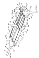
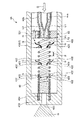
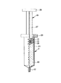
図1および図2は、それぞれ、本発明の塗布具の第1実施形態を示す斜視図、図3および図4は、それぞれ、図1に示す塗布具における開閉手段のA−A線断面図(図3はガス流路が遮断された状態を示し、図4はガス流路が開放された状態を示す)、図5〜図9は、それぞれ、図1に示す塗布具のノズルの概略部分縦断面図(塗布状態の経時的変化を示す図)、図15は、図1に示す塗布具に装填される第1のシリンジ(第2のシリンジも同様)の部分縦断面図である。なお、説明の都合上、図1、図2および図5〜図9中(図10〜図14についても同様)の左側を「先端」、右側を「後端(基端)」といい、図15中の下側を「先端」、上側を「後端」という。また、図1〜図4中、上側を「上」といい、下側を「下」という。また、図5〜図9中(図10〜図14についても同様)では、理解を容易にするため、コイルを構成する線材の外径および隣接する線材同士のピッチを誇張して模式的に図示している。
Hereinafter, the applicator of the present invention will be described in detail based on preferred embodiments shown in the accompanying drawings.
<First Embodiment>
1 and 2 are perspective views showing a first embodiment of the applicator of the present invention, respectively. FIGS. 3 and 4 are cross-sectional views taken along line AA of the opening / closing means in the applicator shown in FIG. 3 shows a state in which the gas flow path is blocked, FIG. 4 shows a state in which the gas flow path is opened), and FIGS. 5 to 9 are schematic partial longitudinal cross-sectional views of the nozzle of the applicator shown in FIG. FIG. 15 is a partial longitudinal sectional view of a first syringe (also the second syringe) loaded in the applicator shown in FIG. 1. For convenience of explanation, the left side of FIGS. 1, 2, and 5 to 9 (the same applies to FIGS. 10 to 14) is referred to as “front end”, and the right side is referred to as “rear end (base end)”. The lower side of 15 is referred to as “front end”, and the upper side is referred to as “rear end”. 1 to 4, the upper side is referred to as “upper” and the lower side is referred to as “lower”. 5 to 9 (the same applies to FIGS. 10 to 14), in order to facilitate understanding, the outer diameter of the wire constituting the coil and the pitch between adjacent wires are exaggerated schematically. Show.
本発明の塗布具1は、液組成が異なる2種の液体(第1の液体L1、第2の液体L2)を混合しながら塗布するものである(図7参照)。図1および図2に示すように、この塗布具1は、第1の液体L1を収納する第1のシリンジ(液体供給手段)2と、第2の液体L2を収納する第2のシリンジ(液体供給手段)3とをそれぞれ装填して用いられる。
The
まず、塗布具1の構成について説明する前に、第1のシリンジ2および第2のシリンジ3の構成について説明する。第1のシリンジ2と第2のシリンジ3とは、ほぼ同様の構成であるため、代表的に第1のシリンジ2について説明する。
First, before describing the configuration of the
図15に示すように、本実施形態における第1のシリンジ2は、外筒(シリンジ外筒)21と、外筒21内で摺動し得るガスケット24と、ガスケット24を外筒21の長手方向(軸方向)に沿って移動操作する押し子(プランジャロッド)26とを備えている。ガスケット24は、押し子26の先端に連結されている。
As shown in FIG. 15, the first syringe 2 in the present embodiment includes an outer cylinder (syringe outer cylinder) 21, a
外筒21は、有底筒状の部材で構成され、先端側底部の中央部には、外筒21の胴部に対し縮径した縮径部(口部)22が一体的に突出形成されている。
The
外筒21の後端外周には、フランジ23が一体的に形成されている。
また、外筒21の外周面には、液量を示す目盛りが付されている。
A
A scale indicating the amount of liquid is attached to the outer peripheral surface of the
外筒21の構成材料としては、例えば、ポリ塩化ビニル、ポリエチレン、ポリプロピレン、環状ポリオレフィン、ポリスチレン、ポリ−(4−メチルペンテン−1)、ポリカーボネート、アクリル樹脂、アクリルニトリル−ブタジエン−スチレン共重合体、ポリエチレンテレフタレート、ポリエチレンナフタレート等のポリエステル、ブタジエン−スチレン共重合体、ポリアミド(例えば、ナイロン6、ナイロン6・6、ナイロン6・10、ナイロン12)のような各種樹脂が挙げられるが、その中でも、成形が容易であり、かつ水蒸気透過性が低い点で、ポリプロピレン、環状ポリオレフィン、ポリエステルのような樹脂が好ましい。なお、外筒21の構成材料は、内部の視認性を確保するために、実質的に透明であるのが好ましい。
As a constituent material of the
このような外筒21内には、弾性材料で構成されたガスケット24が収納されて(挿入されて)いる。ガスケット24の外周部には、複数(2つ)のリング状の突部が全周にわたって形成されており、これらの突部が外筒21の内周面に密着しつつ摺動することで、液密性をより確実に保持するとともに、摺動性の向上が図れる。
In such an
また、ガスケット24には、その後端面に開放する中空部25が形成されている。この中空部25は、後述する押し子26のヘッド部28が螺入(嵌入)される。中空部25の内面には、雌ネジが形成されている。
Further, the
ガスケット24の構成材料としては、特に限定されないが、例えば、天然ゴム、ブチルゴム、イソプレンゴム、ブタジエンゴム、スチレン−ブタジエンゴム、シリコーンゴムのような各種ゴム材料や、ポリウレタン系、ポリエステル系、ポリアミド系、オレフィン系、スチレン系等の各種熱可塑性エラストマー、あるいはそれらの混合物等の弾性材料が挙げられる。
The constituent material of the
押し子26は、横断面が十文字状をなす棒状の本体部27を有している。
本体部27の先端側には、ガスケット24の中空部25内に挿入され、ガスケット24と連結されるヘッド部(連結部)28が形成されている。ヘッド部28の外周には、中空部25の内面の雌ネジと螺合し得る雄ネジが形成されている。この雄ネジを雌ネジと螺合することにより、ガスケット24と押し子26とが連結される。なお、ガスケット24と押し子26は、螺合による連結に限らず、例えば凹凸嵌合等により連結された構成、接着、融着等により固着された構成、一体成形された構成であってもよい。
The
A head portion (connecting portion) 28 that is inserted into the
また、本体部27の後端側には、円盤状のフランジ29が形成されている。
また、押し子26の構成材料としては、前述した外筒21の構成材料として例示したものと同様のものを用いることができる。
A disc-shaped
Further, as the constituent material of the
第1のシリンジ2は、塗布具1に装填される以前に、外筒21とガスケット24とで囲まれた空間(貯液空間)20に、第1の液体L1が充填される。
Before the first syringe 2 is loaded into the
第2のシリンジ3も、第1のシリンジ2と同様に、外筒21と、外筒21内で摺動し得るガスケット24と、ガスケット24を移動操作する押し子26とで構成され、空間20に第2の液体L2が充填される。第2のシリンジ3各部の構成は、第1のシリンジ2と同様であるため、その説明は省略する。
Similarly to the first syringe 2, the
第1のシリンジ2に充填される第1の液体L1と、第2のシリンジ3に充填される第2の液体L2とは、それらの組成(成分)が異なるものである。
The first liquid L1 filled in the first syringe 2 and the second liquid L2 filled in the
本発明においては、第1の液体L1と第2の液体L2とは、塗布具1の用途、使用目的、症例等に応じて適宜選定される。例えば、生体組織接着材の投与に使用する場合、第1の液体L1および第2の液体L2のうちの一方は、トロンビンを含有する液体(溶液等)、他方はフィブリノーゲンを含有する液体(溶液等)とすることができる。
In the present invention, the first liquid L1 and the second liquid L2 are appropriately selected according to the application, purpose of use, case, and the like of the
また、癒着防止材の投与に使用する場合、第1の液体L1および第2の液体L2のうちの一方は、スクシンイミジル基で修飾したカルボキシメチルデキストリンを含有する液体(溶液等)、他方は、リン酸水素二ナトリウムを含有する液体(溶液等)とすることができる。 In addition, when used for administration of the anti-adhesion material, one of the first liquid L1 and the second liquid L2 is a liquid (solution or the like) containing carboxymethyldextrin modified with a succinimidyl group, and the other is phosphorus It can be set as the liquid (solution etc.) containing disodium oxyhydrogen.
このような組み合わせの第1の液体L1および第2の液体L2は、それらを混合すると、変質、すなわち、ゲル化(固化)する。ゲル化することにより、例えば、第1の液体L1と第2の液体L2とが混合したもの(以下、「混合液(混合物)」という)が、塗布された生体組織(目的部位)に確実に留まることができる。また、混合液が目的部位に確実に留まるため、当該目的部位において、生体組織接着材や癒着防止材としての機能を確実に発揮することができる。 The first liquid L1 and the second liquid L2 in such a combination are altered, that is, gelled (solidified) when they are mixed. By gelling, for example, a mixture of the first liquid L1 and the second liquid L2 (hereinafter referred to as “mixed liquid (mixture)”) is surely applied to the applied living tissue (target site). Can stay. In addition, since the mixed solution stays at the target site with certainty, the function as a biological tissue adhesive or an adhesion preventing material can be reliably exhibited at the target site.
なお、第1の液体L1および第2の液体L2の種類および組み合わせは、上述したものに限定されないことは、言うまでもない。 Needless to say, the types and combinations of the first liquid L1 and the second liquid L2 are not limited to those described above.
このような構成の第1のシリンジ2および第2のシリンジ3の各押し子26をそれぞれ押圧操作することより、後述するノズル4の第1の内管44a内に第1の液体L1を、第2の内管44bに第2の液体L2を容易かつ確実に供給することができる。また、各押し子26の押圧操作は、塗布具1の操作者(使用者)により手動で行なわれる。このため、操作者は、混合液の塗布を自身の任意のタイミングで行なうことができる。
By pressing each of the
第1の液体L1が充填された第1のシリンジ2と、第2の液体L2が充填された第2のシリンジ3とが装填される塗布具1は、塗布具本体7と、ノズル4と、操作部8、開閉手段(弁機構)9と、ボンベ(ガス供給手段)300に接続されたチューブ(ガス流路)10を有している(図1参照)。
The
塗布具1を構成する各部について説明する前に、ボンベ300について説明する。
ボンベ300は、その内部空間に高圧の(圧縮された)ガスGが充填されており、当該ガスGを塗布具1(ノズル4)に供給することができる。このボンベ300には、塗布具1に対するガスGの供給/供給停止を制御する開閉自在なバルブ(コック)301が設置されている。塗布具1を使用するときには、バルブ301を開状態にする。なお、ガスGとしては、特に限定されないが、例えば、二酸化炭素が挙げられる。また、ガスGは、無菌状態のものであるのが好ましいが、無菌状態か否かについてはどちらでもよい。また、ボンベ300内の内部圧力(ガス圧)は、0.01MPa以上であるのが好ましく、0.05〜1MPaであるのがより好ましい。
Before describing each part constituting the
The
図1および図2に示すように、塗布具本体7は、第1のシリンジ2および第2のシリンジ3を並べて(並列に)固定するものである。この塗布具本体7は、基部71と、基部71の先端に設けられた前板(第1の係合部)72と、基部71の後端に設けられた後板(第2の係合部)73と、基部71の後板73付近に設けられた指掛け部751および752とを有している。
As shown in FIGS. 1 and 2, the
基部71は、その上部に、横断面がほぼ半円弧状をなす凹部711および712が並列に設けられている。凹部711には、第1のシリンジ2の外筒21が収納され、凹部712には、第2のシリンジ3の外筒21が収納される。
The base 71 is provided with
基部71の先端には、前板72が設けられている。この前板72には、凹部711および712のそれぞれに対応する位置に、溝721および722が形成されている。第1のシリンジ2および第2のシリンジ3を装填するとき、溝721には、第1のシリンジ2の縮径部22が挿入され、溝722には、第2のシリンジ3の縮径部22が挿入される。
A
基部71の後端には、後板73が設けられている。この後板73には、凹部711および712のそれぞれに対応する位置に、凹部731および732が形成されている。第1のシリンジ2および第2のシリンジ3を装填するとき、凹部731には、第1のシリンジ2のフランジ23(基端部)が係合し(挿入され)、凹部732には、第2のシリンジ3のフランジ23(基端部)が係合する。
A
このように、塗布具本体7では、前板72に各縮径部22が係合するとともに、後板73に各フランジ23が係合することにより、第1のシリンジ2と第2のシリンジ3とを確実に並列に固定することができる。
As described above, in the applicator
基部71の後板73付近には、指掛け部751および752が設けられている。指掛け部751および752には、それぞれ、塗布具1を使用するときに使用者の指を掛けることができる。指掛け部751は、上方に突出した板片で構成され、指掛け部752は、下方に突出した板片で構成されている。また、各指掛け部751および752は、それぞれ、先端方向に臨む面が円弧状(湾曲凹状)をなすものである。
Finger hooks 751 and 752 are provided near the
塗布具本体7は、当該塗布具本体7を構成する各部が一体的に形成されたものであってもよいし、各部がそれぞれ別体で構成されこれらを接合したものであってもよい。
The applicator
塗布具本体7の構成材料としては、特に限定されず、例えば、各種金属材料や各種プラスチック等を単独または組み合わせて用いることができる。このような材料を用いた場合、例えば金型成形により塗布具本体7を容易に製造することができる。
The constituent material of the applicator
塗布具本体7の後端側には、操作部8が塗布具本体7に対してその長手方向に移動可能に設置されている。この操作部8は、第1のシリンジ2の押し子26と第2のシリンジ3の押し子26とを先端方向(図1、図2および図4中の矢印C方向)へ押圧操作する部位である。操作部8は、第1のシリンジ2および第2のシリンジ3の押し子26のフランジ29同士を連結する連結部81と、連結部81の後端側に位置する押圧部82と、連結部81から先端方向に向かって延在するレール部83とを有している。
On the rear end side of the applicator
連結部81には、上方へ向かって開放する凹部811および812がそれぞれ設けられている。凹部811は、第1のシリンジ2の押し子26のフランジ29に対応した形状をなしており、当該フランジ29が係合する(図2参照)。また、凹部812は、第2のシリンジ3の押し子26のフランジ29に対応した形状をなしており、当該フランジ29が係合する(図2参照)。
The connecting
このような構成の連結部81により、第1のシリンジ2および第2のシリンジ3の押し子26のフランジ29同士を確実に連結、固定することができ、よって、これらの押し子26を一括して矢印C方向に移動させることができる。
With the connecting
また、連結部81には、凹部811と凹部812との間に、筒状をなす筒状部813が設けられている。この筒状部813は、その軸線が図1中(図2も同様)上下方向と平行となるように設けられている。また、筒状部813には、開閉手段9のほとんどが収納されている。
Further, the connecting
連結部81の筒状部813の外周部には、長尺状をなすレール部83が先端方向に向かって突出形成されている。このレール部83は、塗布具本体7の基部71に設けられ、長尺状をなすガイド713に挿入される。操作部8の矢印C方向への押圧操作によりレール部83がガイド713に案内されることとなり、よって、前記押圧操作を円滑に行うことができる。
A
連結部81の筒状部813の後端側には、板状をなす押圧部82が筒状部813に対して塗布具本体7の長手方向に移動可能に設置されている。
On the rear end side of the
この押圧部82は、塗布具1を使用する、すなわち、混合液を患部等に塗布するとき、使用者によって押圧される部位である。塗布具1を使用するとき、例えば指掛け部751に人差し指を掛け、指掛け部752に中指を掛け、押圧部82に親指を掛けることができる。これにより、塗布具1を安定して確実に把持することができる。また、操作部8(押圧部82)の押圧操作を円滑かつ確実に行うことができ、よって、塗布具1の操作性が向上する。
The
また、押圧部82は、後述する開閉手段9の第2の接続部92に連結されている。
The
操作部8の構成材料としては、特に限定されず、例えば、塗布具本体7についての説明で挙げたような材料を用いることができる。このような材料を用いた場合、例えば金型成形により操作部8を容易に製造することができる。
The constituent material of the
前述したように、操作部8の筒状部813には、開閉手段9が設置されている。開閉手段9は、ボンベ300からノズル4に至るガスGの流れを遮断/開放するものである。この開閉手段9を介して、すなわち、開閉手段9の作動により、第1のチューブ101と第2のチューブ102とが遮断(図3参照)/連通(図4参照)する。
As described above, the opening / closing means 9 is installed in the
図3および図4に示すように、開閉手段9は、第1のチューブ101に接続された第1の接続部91と、第2のチューブ102に接続された第2の接続部92と、第1の接続部91内に収納され、開閉自在な弁部93とを有している。
As shown in FIGS. 3 and 4, the opening / closing means 9 includes a first connecting
第1の接続部91は、管状をなすものである。この第1の接続部91の内腔部には、下流側に位置し、弁部93が収納される収納部912が設けられている。また、第1の接続部91の内腔部には、収納部912の上流側の内径より縮径した縮径部913が設けられており、当該縮径部913と収納部912との境界に内径が急峻に変化した段差部911が形成されている。
The first connecting
第2の接続部92は、管状をなすものである。前述したように、第2の接続部92は、操作部8の押圧部82に連結されている。第2の接続部92は、下端部921が弁部93のシール部材94に支持されており、当該シール部材94を介して第1の接続部91の下流側に設置されている。この第2の接続部92は、第1の接続部91に対して、軸線同士が一致する第1の姿勢(図3に示す状態)と、下端部921を支点として軸線が押圧部82(操作部8)の矢印C方向(操作方向)に傾倒する第2の姿勢(図4に示す状態)とに変位可能に設置されている。
The
弁部93は、弾性材料で構成されたシール部材94と、シール部材94より上流側に位置するフランジ部95と、フランジ部95をシール部材94側に付勢する付勢部96とを有している。
The valve portion 93 includes a
シール部材94は、その形状がリンク状をなすものである。このシール部材94は、その内周部941が第2の接続部92の下端部921の外周部922に密着している。また、シール部材94の外周部942は、第1の接続部91の収納部912の内周部914に密着している。このようなシール部材94により、当該シール部材94を介して、第1の接続部91と第2の接続部92とが気密に連結される。
The
フランジ部95は、その外径が第2の接続部92の外径より拡径したものである。このフランジ部95は、第2の接続部92の下端面に、間隙97を介して、対向配置されている。
The
付勢部96は、本実施形態では圧縮コイルバネで構成されたものであり、それが圧縮された状態で、上端部961がフランジ部95に当接し、下端部962が第1の接続部91の段差部911に当接している。これにより、フランジ部95を確実にシール部材94側に付勢することができる。
In the present embodiment, the urging
このような構成の弁部93では、フランジ部95は、第2の接続部92が第1の姿勢のとき、すなわち、第2の接続部92に外力が付与されていないとき、付勢部96に付勢されてシール部材94に気密に密着する(図3参照)。これにより、弁部93は閉状態となる。
In the valve portion 93 having such a configuration, the
また、操作部8の押圧部82による矢印C方向へ押圧力が第2の接続部92に作用すると、当該第2の接続部92は、第1の姿勢から第2の姿勢へ変位する。このとき、フランジ部95は、付勢部96の付勢力に抗して変位することとなり、これにより、フランジ部95の周縁部951の一部(または全部)がシール部材94から離間して、当該シール部材94との間に間隙98が生じる(図4参照)。これにより、ガスGは間隙98を介して第1の接続部91から第2の接続部92に流れ込む、すなわち、弁部93は開状態となる。
Further, when a pressing force in the direction of arrow C by the
以上のような構成の開閉手段9では、操作部8による押圧操作に連動して、弁部93が確実に開/閉することができる。これにより、弁部93が閉状態のとき、ボンベ300からノズル4に至るガスGの流れを確実に遮断することができ、弁部93が開状態のとき、当該ガスGの流れを確実に開放することができる。
In the opening / closing means 9 configured as described above, the valve portion 93 can be reliably opened / closed in conjunction with the pressing operation by the
なお、第1の接続部91、第2の接続部92、フランジ部95および付勢部96の構成材料としては、特に限定されないが、例えば、各種金属材料や各種プラスチック等を単独または組み合わせて用いることができる。
In addition, although it does not specifically limit as a constituent material of the
また、シール部材94の構成材料としては、特に限定されないが、例えば、天然ゴム、ブチルゴム、イソプレンゴム、ブタジエンゴム、スチレン−ブタジエンゴム、シリコーンゴムのような各種ゴム材料を用いることができる。
The constituent material of the
図1、図2に示すように、塗布具本体7の前板72には、ノズル4が設置されている。このノズル4は、第1のシリンジ2の縮径部22を通過した第1の液体L1と第2のシリンジ3の縮径部22を通過した第2の液体L2と(混合液)を、チューブ10を通過したガス(気体)Gとともに吐出する(噴出する)ものである。
As shown in FIGS. 1 and 2, the nozzle 4 is installed on the
固定部材41は、例えば金属材料や樹脂材料で構成され、外形形状がブロック状をなすものである。この固定部材41は、先端および基端に開口する中空部を有している。このような固定部材41は、その基端開口部411が塗布具本体7の前板72に係合する。これにより、ノズル4が塗布具本体7に固定される。
The fixing
ノズル4は、第1のシリンジ2の縮径部22に接続され、内部を第1の液体L1が通過する第1の内管44a(液体流路)と、第2のシリンジ3の縮径部22に接続され、内部を第2の液体L2が通過する第2の内管44b(液体流路)と、第1の内管44aおよび第2の内管44bが挿入された外管43と、第2のチューブ102に接続され、外管43内にガスGを供給する供給管(ガス供給管(図示せず))と、ノズル4を塗布具本体7の前板72に固定する固定部材41とを有している。
The nozzle 4 is connected to the reduced diameter portion 22 of the first syringe 2, and the first
第1の内管44a(コイル42を除く部分)、第2の内管44b(コイル42を除く部分)、外管43および前記供給管は、それぞれ、硬質材料で構成されているものでも、軟質材料、弾性材料等で構成され、可撓性を有するものでもよい。本実施形態では、可撓性を有するものとなっている。その構成材料としては、例えば、ポリ塩化ビニル、ポリエチレン、ポリプロピレン、環状ポリオレフィン、ポリスチレン、ポリ−(4−メチルペンテン−1)、ポリカーボネート、アクリル樹脂、アクリルニトリル−ブタジエン−スチレン共重合体、ポリエチレンテレフタレート、ポリエチレンナフタレート等のポリエステル、ブタジエン−スチレン共重合体、ポリアミド(例えば、ナイロン6、ナイロン6・6、ナイロン6・10、ナイロン12)のような各種の軟質または硬質樹脂、天然ゴム、ブチルゴム、イソプレンゴム、ブタジエンゴム、スチレン−ブタジエンゴム、シリコーンゴムのような各種ゴム材料や、ポリウレタン系、ポリエステル系、ポリアミド系、オレフィン系、スチレン系等の各種熱可塑性エラストマー、ステンレス鋼、アルミニウム、銅または銅系合金等の各種金属材料、各種ガラス、アルミナ、シリカ等の各種セラミックスが挙げられる。
The first
第1の内管44aと第2の内管44bとは、ほぼ同様の構成であるため、代表的に第1の内管44aについて説明する。
Since the first
第1の内管44aは、長尺な管状体で構成され、その基端部が第1のシリンジ2の縮径部22に接続されて(嵌合して)いる。これにより、第1の内管44aに第1のシリンジ2から第1の液体L1を確実に供給することができる。
The first
また、第1の内管44aは、その先端に開口した噴出口442を有している。この噴出口442は、操作部8を押圧操作した際に当該第1のシリンジ2の縮径部22から流出した第1の液体L1と、ボンベ300から流出したガスGとを噴出する部位である(図7参照)。
The first
このような第1の内管44aおよび第2の内管44bは、外管43内に挿入されている(図5〜図9参照)。この外管43は、長尺な管状体で構成され、その基端部が固定部材41の先端開口部412に接続されている。前記供給管を介して供給されたガスGは、外管43と第1の内管44aと第2の内管44bとの間(間隙(ガス流路))を通過することとなる。
Such first
また、外管43は、その先端部に設けられた先端壁部432を有し、先端が閉塞したものとなっている。第1の内管44aおよび第2の内管44bは、それぞれ、先端壁部432を貫通しており、各噴出口442が露出している。外管43の先端壁部432と第1の内管44aおよび第2の内管44bの先端部との間には、例えばシール部材が設置されており、外管43内の気密性が維持されている。これにより、外管43の先端壁部432と第1の内管44aおよび第2の内管44bの先端部との間から、ガスGが漏出するのが確実に防止されている。
Moreover, the outer tube |
図1、図2に示すように、固定部材41は、ノズル4の基端部に配置されている。この固定部材41は、先端開口部412と基端開口部411とを有する中空体で構成されている。先端開口部412には、外管43の基端部が気密に接続されており、基端開口部411は、塗布具本体7の前板72に接続・固定されている。また、固定部材41の内側には、第1の内管44aの第1のシリンジ2との接続部、第2の内管44bの第2のシリンジ3との接続部、前記供給管のチューブ10との接続部とが位置している。これにより、各接続部を覆うことができ、よって、各接続部を保護することができる。
As shown in FIGS. 1 and 2, the fixing
さて、図5〜図9に示すように、第1の内管44aは、その先端部(噴出口442近傍の部分)がコイル42で構成されている。また、これと同様に、第2の内管44bも、その先端部(噴出口442近傍の部分)がコイル42で構成されている。これらのコイル42は、同一の構成であるため、以下、第1の内管44a側のコイル42について代表的に説明する。
Now, as shown in FIGS. 5 to 9, the first
コイル42は、第1の内管44aの途中(先端部)を切断し(除去し)、その切断部を補完するように、すなわち、切断部を介して第1の内管44aの上流側(基端側)の部分と下流側(先端側)の部分とを接合するように設置されている。この接合方法としては、特に限定されないが、例えば、融着(熱融着、高周波融着、超音波融着等)、接着(接着剤や溶媒による接着)等の方法が挙げられる。
The
このコイル42は、線材422を螺旋状に巻回してなるものである。このコイル42では、隣接する線材同士が互いに離間しており、それらの間に間隙423が形成されている。外管43内を通過したガスGは、間隙423を介して、コイル42内に流入することができる。これにより、コイル42内に流入したガスGは、第1の液体L1とともに、噴出口442から噴出する(図7参照)。そして、噴出口442から噴出した第1の液体L1は、霧状になり、これと同様に霧状に噴出した第2の液体L2と混合して患部に塗布される。
The
コイル42は、前述したように線材422を螺旋状に巻回してなるものであり、この構造により、間隙423も螺旋状となる。これにより、ガスGは、間隙423を介して、コイル42の周方向のいずれの部分からも第1の内管44a内に流入することができる。これにより、ガスGを第1の内管44a内に過不足なく供給することができ、よって、噴出口442から噴出する第1の液体L1が確実に霧状となる。このように霧状となることにより、第1の液体L1と第2の液体L2とが均一に混合し、好適な状態(混合が均一な状態)で患部へ塗布される。また、図8に示すように、第1の液体L1の吐出が停止した際には、コイル42の間隙423を介して流入したガスGが、第1の内管44a内のコイル42よりも先端側の部分の第1の液体L1を確実に外方へ押し出す(吹き飛ばす)。これにより、噴出口442に第1の液体L1が残留するのが防止される。よって、当該噴出口442(ノズル4)に目詰まりが生じるのが防止され(図9参照)、また、噴出口442から第1の液体L1の残液が漏出するのが確実に防止される。
The
また、コイル42を構成する線材422は、その横断面形状が円形をなすものである。これにより、コイル42の内周部には、隣接する線材422の外周面同士の間で画成された螺旋状の溝423aが形成されることとなる。この溝423aは、間隙423の内側の部分となっている。コイル42内を第1の液体L1が通過する際、この第1の液体L1には、溝423aによって旋回流が生じる(図7参照)。これにより、第1の液体L1は、噴出口442から勢いよく噴射され、よって、第2の液体L2とともに(混合液となって)患部に確実に塗布される。
The
なお、線材422の線径は、特に限定されないが、例えば、0.05〜1.0mmであるのが好ましく、0.1〜0.5mmであるのがより好ましく、0.1〜0.15mmであるのがさらに好ましい。
The wire diameter of the
また、隣接する線材422同士の間隙距離(ギャップ長)uは、特に限定されないが、例えば、0〜0.1mmであるのが好ましく、0〜0.05mmであるのがより好ましい。
Further, the gap distance (gap length) u between
また、線材422の構成材料は、特に限定されず、例えば、前述した第1の内管44aと同様の可撓性(弾性)を有する材料を用いることができる。
Moreover, the constituent material of the
また、コイル42は、第1の液体L1や第2の液体L2に対して撥水性、すなわち、疎水性を有しているのが好ましい。これにより、コイル42の間隙423を介して、当該コイル42(第1の内管44a)内の第1の液体L1が外管43内に流れ込む(漏れる)のが確実に防止される。このようなコイル42は、疎水性を有する材料で構成されたもの、または、その線材422の外周面が疎水化処理が施されたものを用いることができる。疎水性を有する材料(構成材料)としては、例えば、ポリテトラフルオロエチレン(PTFE)、テトラフルオロエチレンとヘキサフルオロプロピレンの共重合体(FEP)、テトラフルオロエチレンとパーフルオロアルキルビニルエーテルの共重合体(PFA)、ポリクロロトリフルオロエチレン(PCTFE)、ポリフッ化ビニリデン(PVDF)、エチレンとテトラフルオロエチレンの共重合体(ETFE)、エチレンとクロロトリフルオロエチレンの共重合体(ECTFE)、ポリプロピレン(PP)等が挙げられる。また、このような樹脂材料の他、ステンレス鋼等のような金属材料も用いることができる。また、疎水化処理の方法としては、特に限定されず、例えば、線材422の外周面(コイル42の表面)に、前記疎水性を有する材料をコーティングする方法等が挙げられる。
The
また、コイル42は、本実施形態では第1の内管44aの壁部の先端部を構成しているが、これに限定されず、例えば、第1の内管44aの壁部の全体を構成していてもよい。
Moreover, although the
また、第1の内管44a側のコイル42と第2の内管44b側のコイル42とは、互いにピッチpが同じものであるが、ピッチpが異なっていてもよい。例えば、第1の液体L1および第2の液体L2のうち、一方の液体の粘度が他方の液体の粘度よりも高い場合、一方の液体が通過するコイルのピッチpを、他方の液体が通過するコイルのピッチpよりも大きくしてもよい。
Further, the
次に、使用可能状態となった、すなわち、第1の液体L1が充填された第1のシリンジ2と、第2の液体L2が充填された第2のシリンジ3とが装填され、かつボンベ300に接続された状態の塗布具1の作動状態について説明する。
Next, the first syringe 2 filled with the first liquid L1 and the
第1のシリンジ2および第2のシリンジ3には、それぞれ、患部に塗布するのに必要な(十分な)程度の液量の第1の液体L1および第2の液体L2が充填されている。また、ボンベ300は、バルブ301が開状態となっており、塗布具1に対してガスGを供給可能となっている。
The first syringe 2 and the
また、塗布具1では、シール部材94にフランジ部95を押し付ける付勢部96の力(付勢力)に抗して、シール部材94とフランジ部95との間に間隙98を生じさせる力、すなわち、第2の接続部92を第1の姿勢から第2の姿勢へ傾倒させる矢印C方向への押圧力は、第1のシリンジ2の押し子26と第2のシリンジ3の押し子26とを先端方向に移動させる力より小さくなるように設定されている。このような設定を行う方法としては、例えば、付勢部96のバネ定数、各液体の粘度、各外筒21の内径等の諸条件を適宜設定することより可能となる。
Further, in the
このような塗布具1に対して、まず、例えば塗布具本体7の指掛け部751に人差し指を掛け、指掛け部752に中指を掛け、操作部8の押圧部82に親指を掛ける。このとき、第1の内管44aには第1の液体L1が供給されておらず、第2の内管44bにも第2の液体L2が供給されておらず、外管43にもガスGが供給されていない(図5参照)。このため、ノズル4からは、ガスG、第1の液体L1および第2の液体L2は、噴出されていない。
For such an
次に、この状態で、親指で押圧部82を押圧操作すると、まず、第2の接続部92が傾倒して、シール部材94とフランジ部95との間に間隙98が生じ、この間隙98を介してガスGが流通する(図4参照)。これにより、ガスGは、第2のチューブ102を介して前記供給管に流入し、よって、さらに外管43内を通過する。そして、ガスGは、各コイル42付近に達すると、当該コイル42の間隙423を介して、第1の内管44aおよび第2の内管44b内に流入する。各噴出口442からは、ガスGが高速に噴出する(図6参照)。
Next, when the
また、親指による押圧部82に対する押圧操作は、操作部8全体、すなわち、各押し子26を先端方向に移動するまでには至っていない。このため、第1の内管44aおよび第2の内管44bには、未だ第1の液体L1および第2の液体L2が供給されていない。
Further, the pressing operation with respect to the
さらに、押圧部82を押圧すると、第2の接続部92の傾倒が限界となり、親指からの押圧力が押圧部82を介して連結部81に伝達される。これにより、連結部81(操作部8全体)が移動し始め、よって、第1のシリンジ2から第1の液体L1が押し出されるとともに、第2のシリンジ3からも第2の液体L2が押し出される。この押し出された第1の液体L1は、コイル42内でガスGと合流し、当該ガスGとともに、第1の内管44aの噴出口442から噴出する(図7参照)。また、第2の液体L2は、第1の液体L1とほぼ同様に、コイル42内でガスGと合流し、当該ガスGとともに、第2の内管44bの噴出口442から吐出する(図7参照)。
Further, when the
各噴出口442から噴出した第1の液体L1および第2の液体L2は、それぞれ、高速に噴出するガスGによって、霧状になる。これにより、第1の液体L1と第2の液体L2とは、互いに混合して患部に塗布される。
The first liquid L1 and the second liquid L2 ejected from each
患部に対する所定量の塗布が完了した後、親指の押圧部82(操作部8)に対する押圧力を緩めていくと、まず、操作部8全体の移動が停止する。これにより、各押し子26の移動が停止し、よって、第1の液体L1および第2の液体L2の噴出がそれぞれ停止する(図8参照)。このとき、押圧部82の押圧による第2の接続部92の第2の姿勢が維持されているため、ガスGは、まだ噴出されている(図8参照)。これにより、第1の内管44a内では、コイル42よりも先端側の部分の第1の液体L1が、コイル42の間隙423を介して流入したガスGによって、噴出口442から押し出される。その結果、第1の液体L1の先端P1がコイル42の基端部付近に位置する。また、これと同様に、第2の内管44b内でも、コイル42よりも先端側の部分の第2の液体L2が、コイル42の間隙423を介して流入したガスGによって、噴出口442から押し出される。その結果、第2の液体L2の先端P2がコイル42の基端部付近に位置する。
After the application of a predetermined amount to the affected area is completed, when the pressing force applied to the thumb pressing section 82 (operation section 8) is loosened, the movement of the
このような構成により、各噴出口442付近にそれぞれ第1の液体L1および第2の液体L2が残留するのが防止され、また、これら液体同士が混合して(接触して)ゲル化するのが防止される。これにより、各噴出口442に目詰まりが生じるのが確実に防止される。
With such a configuration, it is possible to prevent the first liquid L1 and the second liquid L2 from remaining in the vicinity of each
さらに、親指の押圧部82に対する押圧力を緩めていくと、遂には、押圧部82を押圧していた親指が当該押圧部82から離間する。これにより、第2の接続部92に対する押圧力が解除されて、第2の接続部92が第1の姿勢に戻る。これにより、シール部材94とフランジ部95との間の間隙98がなくなる、すなわち、シール部材94とフランジ部95の周縁部951の全周とが互いに密着する(図3参照)。このとき、外管43へのガスGの供給が停止する(図9参照)。
Furthermore, when the pressing force of the thumb against the
このように、塗布具1では、当該塗布具1に対する操作が完了した際に、すなわち、塗布具1の使用後(塗布後)に、ノズル4に目詰まりが生じるのが防止される。そして、この目詰まりが生じていない状態(好適な状態)の塗布具1を再度、患部への塗布に用いることができる。
Thus, the
また、塗布具1は、ノズル4からは、ガスGが、第1の液体L1および第2の液体L2に先立って吐出されるよう構成されている。これにより、第1の液体L1および第2の液体L2のみが患部に噴出され塗布されるのを防止することができる。また、先立って噴出されたガスGにより、第1の液体L1および第2の液体L2がそれぞれ確実に霧状となって噴出され、よって、これらの液体同士が確実に混合する。
The
また、塗布具1では、ガスGの供給が停止した(図9に示す状態)後も、外管43内の残圧によって、ガスGがコイル42の間隙423を介して第1の内管44a内に流入するため、コイル42よりも先端側の部分の第1の液体L1をさらに吹き飛ばすことができる。これにより、各噴出口442に目詰まりが生じるのがより確実に防止される。
Further, in the
<第2実施形態>
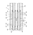
図10〜図12は、それぞれ、本発明の塗布具(第2実施形態)のノズルの概略部分縦断面図(塗布状態の経時的変化を示す図)である。
<Second Embodiment>
10 to 12 are schematic partial longitudinal sectional views of the nozzle of the applicator (second embodiment) of the present invention (showing changes over time in the application state), respectively.
以下、これらの図を参照して本発明の塗布具の第2実施形態について説明するが、前述した実施形態との相違点を中心に説明し、同様の事項はその説明を省略する。 Hereinafter, the second embodiment of the applicator of the present invention will be described with reference to these drawings. However, the difference from the above-described embodiment will be mainly described, and description of similar matters will be omitted.
本実施形態は、内管の構成が異なる、すなわち、合流部が形成されていること以外は前記第1実施形態と同様である。 The present embodiment is the same as the first embodiment except that the configuration of the inner pipe is different, that is, a merging portion is formed.
図10〜図12に示すノズル4Aでは、第1の内管44aと第2の内管44bとが、それらの先端側の部分(先端部)で、1つに合流している。これにより、各内管の内部空間同士が合流する合流部52が形成される。この合流部52では、第1の液体L1と第2の液体とが合流して均一かつ確実に混合して、混合液となる。また、合流部52は、その全体がコイル42で構成されている。
In the
また、外管43の先端壁部432には、その厚さ方向に貫通する貫通孔が形成されている。この貫通孔は、合流部52(コイル42の内側)と連通しており、当該合流部52で生成された混合液が噴出する噴出口433として機能する(図11参照)。先端壁部432の裏面(基端面)には、噴出口433の外周側に当該噴出口433と同心的に形成されたリング状の凹部434が形成されている。凹部434には、合流部52を構成するコイル42の先端部が挿入される。これにより、コイル42は、その先端部が外管43に対して固定される(支持される)。
Further, a through hole penetrating in the thickness direction is formed in the distal
コイル42の基端部(後端部)は、固定部材53を介して、外管43に対して支持固定されている。固定部材53は、コイル42の基端外周部と外管43の内周部との間に配置された壁状をなすものである。また、固定部材53には、その厚さ方向に貫通する少なくとも1つの貫通孔531が形成されており、当該貫通孔531をガスが通り抜ける(通過する)ことができる(図11、図12参照)。固定部材53は、例えば、ポリウレタン、シリコーンゴム等のポッティング材により構成されている。
A proximal end portion (rear end portion) of the
このようにコイル42の両端部(特に基端部)が支持されていることにより、コイル42内を混合液が通過した際、その混合液の前方へ向かう力によってコイル42が不本意にズレるのを確実に防止することができる。
Since both ends (particularly the base end) of the
前述したように、合流部52は、その全体がコイル42で構成されている。これにより、操作部8の操作により、第1の液体L1と第2の液体L2との噴出が停止した際、コイル42の間隙423を介して合流部52(コイル42)に流入したガスGによって、合流部52内の混合液を噴出口433から確実に吹き飛ばすことができる(図12参照)。これにより、噴出口433に混合液が残留するのが防止され、よって、当該噴出口433(ノズル4A)に目詰まりが生じるのが防止される。
As described above, the joining
また、コイル42は、隣接する線材422同士のピッチpが変化するものである。図11に示すように、混合液が噴出しているときには、主にガスGが線材422を押圧する力(周囲のガス圧)によって、各線材422がそれぞれ押圧されて、コイル42の基端側の部分ではピッチpが自然状態(図10に示す状態)のときよりも広がり、コイル42の先端側の部分ではピッチpが狭くなる。これにより、ガスGがコイル42の先端側の部分よりも基端側の部分からより多く流入する。これにより、混合液をできる限り基端側から強く押し出すことができ、よって、当該混合液が勢いよく噴出し、確実に患部に塗布される。
In addition, the
そして、混合液の噴出が停止し、さらにガスGの噴出が停止したときには、線材422を押圧する力が消失し、コイル42が自然状態に復元する、すなわち、コイル42の基端側の部分ではピッチpが狭く(元の大きさと)なり、コイル42の先端側の部分ではピッチpが広く(元の大きさと)なる。
When the ejection of the mixed liquid stops and further the ejection of the gas G stops, the force that presses the
このように混合液とガスGとの流量に応じてピッチpが可変となる方法としては、特に限定されず、例えば、線材422の線径や構成材料等の諸条件を適宜選定する方法が挙げられる。
The method for changing the pitch p in accordance with the flow rates of the mixed liquid and the gas G in this way is not particularly limited, and examples thereof include a method of appropriately selecting various conditions such as the wire diameter and the constituent material of the
また、前述したようにコイル42内では旋回流が生じる(図11参照)。これにより、コイル42内では、合流した第1の液体L1と第2の液体L2とが攪拌され、よって、これらの液体が均一に混合した混合液を噴出することができる。
Further, as described above, a swirl flow is generated in the coil 42 (see FIG. 11). Thereby, in the
また、コイル42の間隙423を介して流入したガスGは、混合液中では気泡となる。この気泡によっても、第1の液体L1と第2の液体L2とは、合流部52を通過する過程で攪拌される。これにより、さらに攪拌効率が向上する。
Further, the gas G flowing in through the
特に、両液体の粘度が互いに異なる場合には、これら液体同士を単に合流するだけでは均一な混合液になり難いが、本発明では、第1の液体L1と第2の液体L2とを攪拌してそれらの混合を促進する攪拌作用が発揮されるため、均一な混合液を得る。 In particular, when the viscosities of the two liquids are different from each other, it is difficult to form a uniform mixed liquid by simply joining the liquids. However, in the present invention, the first liquid L1 and the second liquid L2 are stirred. Thus, a stirring action that promotes the mixing of them is exhibited, so that a uniform mixed solution is obtained.
なお、合流部52は、本実施形態ではその全体がコイル42で構成されているが、これに限定されず、例えば、基端側の部分(基端部)がコイル42で構成されていてもよい。
In addition, although the confluence | merging
<第3実施形態>
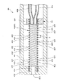
図13は、本発明の塗布具(第3実施形態)のノズルの概略部分縦断面図である。
<Third Embodiment>
FIG. 13 is a schematic partial longitudinal sectional view of the nozzle of the applicator (third embodiment) of the present invention.
以下、この図を参照して本発明の塗布具の第3実施形態について説明するが、前述した実施形態との相違点を中心に説明し、同様の事項はその説明を省略する。
本実施形態は、コイルの設置状態が異なること以外は前記第2実施形態と同様である。
Hereinafter, the third embodiment of the applicator of the present invention will be described with reference to this drawing. However, the difference from the above-described embodiment will be mainly described, and description of similar matters will be omitted.
This embodiment is the same as the second embodiment except that the installation state of the coils is different.
図13に示すノズル4Bでは、合流部52を構成するコイル42の先端部が、外管43の先端壁部432を貫通している。このため、コイル42の先端(噴出口424)が外管43の先端432aよりも突出している(以下この突出した部分を「突出部425」と言う)。また、コイル42の先端は、混合液が噴出する噴出口424として機能する。
In the nozzle 4 </ b> B shown in FIG. 13, the distal end portion of the
このような構成のノズル4Bでは、図13に示すように塗布具1を使用する際にノズル4の先端、すなわち、噴出口424が例えば臓器900に当接して押圧した場合、突出部425が収縮して、その押圧力を緩和する緩衝部として機能する。これにより、臓器900が過剰にノズル4Bによって押圧されるのが防止または抑制される。
In the nozzle 4B having such a configuration, when the
また、図13に示す状態では、噴出口424が臓器900によって閉塞されてしまうが、突出部425での間隙423を介して、混合液が外部に流出することができる。これにより、混合液やガスGがコイル42内を逆流して、各内管の下流側へ向かったり、コイル42の間隙を介して外管43内に流入したりするのを確実に防止することができる。
In the state shown in FIG. 13, the
<第4実施形態>
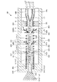
図14は、本発明の塗布具(第4実施形態)のノズルの概略部分縦断面図である。
<Fourth embodiment>
FIG. 14 is a schematic partial longitudinal sectional view of the nozzle of the applicator (fourth embodiment) of the present invention.
以下、この図を参照して本発明の塗布具の第4実施形態について説明するが、前述した実施形態との相違点を中心に説明し、同様の事項はその説明を省略する。
本実施形態は、コイルの配置位置が異なること以外は前記第2実施形態と同様である。
Hereinafter, the fourth embodiment of the applicator of the present invention will be described with reference to this drawing. However, the difference from the above-described embodiment will be mainly described, and description of similar matters will be omitted.
This embodiment is the same as the second embodiment except that the arrangement position of the coils is different.
図14に示すノズル4Cでは、合流部52aは、その途中に、内径が先端方向に向かって漸減したテーパ部521を有している。このテーパ部521を介して、合流部52は、先端側の内径が小さい小径部522と、基端側の内径が大きい大径部523とに分けることができる。小径部522の先端開口は、混合液(第1の液体L1と第2の液体L2とが混合したもの)が、ガスGとともに噴出する噴出口524として機能する。
In the nozzle 4 </ b> C shown in FIG. 14, the merging
また、ノズル4Cでは、第1の内管44aおよび第2の内管44bにそれぞれコイル42が設置されている。各コイル42は、合流部52近傍に配置されている。
Further, in the nozzle 4C, coils 42 are respectively installed in the first
このような構成のノズル4Cでは、操作部8の操作により、第1の液体L1と第2の液体L2との噴出が停止した際、各コイル42の間隙423を介して流入したガスGによって、合流部52内の混合液のみならず、第1の内管44a(コイル42)内の第1の液体L1と、第2の内管44b(コイル42)内の第2の液体L2も噴出口524から確実に吹き飛ばすことができる。これにより、噴出口524に第1の液体L1や第2の液体L2が残留して、当該噴出口524に目詰まりが生じるのがより確実に防止される。
In the nozzle 4 </ b> C having such a configuration, when the ejection of the first liquid L <b> 1 and the second liquid L <b> 2 is stopped by the operation of the
なお、コイル42は、図14に示す構成では第1の内管44aおよび第2の内管44bにそれぞれ設置されているが、これに限定されず、例えば、第1の内管44aおよび第2の内管44bのうちの一方の内管に設置されていてもよい。例えば第1の内管44aにのみコイル42が設置されている場合、操作部8の操作により、第1の液体L1と第2の液体L2との噴出が停止した際、第1の内管44a側のコイル42の間隙423を介して当該第1の内管44a内に流入したガスGによって、合流部52内の混合液と、第1の内管44a(コイル42)内の第1の液体L1とが噴出口524から吹き飛ばされる。このとき、合流部52に連通する第2の内管44b内の圧力が減少するため、当該第2の内管44b内の第2の液体L2も合流部52に流入して、噴出口524から吹き飛ばされる。これにより、噴出口524に第1の液体L1や第2の液体L2が残留して、当該噴出口524に目詰まりが生じるのがより確実に防止される。
In the configuration shown in FIG. 14, the
以上、本発明の塗布具を図示の実施形態について説明したが、本発明は、これに限定されるものではなく、塗布具を構成する各部は、同様の機能を発揮し得る任意の構成のものと置換することができる。また、任意の構成物が付加されていてもよい。 As mentioned above, although the applicator of the present invention has been described with respect to the illustrated embodiment, the present invention is not limited to this, and each part constituting the applicator has any configuration that can exhibit the same function. Can be substituted. Moreover, arbitrary components may be added.
また、本発明の塗布具は、前記各実施形態のうちの、任意の2以上の構成(特徴)を組み合わせたものであってもよい。 Moreover, the applicator of the present invention may be a combination of any two or more configurations (features) of the above embodiments.
また、内管の一部を構成するコイルは、隣接する線材同士が離間したものであるが、これに限定されず、隣接する線材同士が当接したものであってもよい。隣接する線材同士が当接したコイルである場合には、ガス圧によって、隣接する線材同士が離間し、コイル内にガスが流入することとなる。この場合、内管のコイル以外の部分は、柔軟性を有するのが好ましい。また、コイルの後端部と内管のコイル以外の部分との接続は、固定されていない状態である、すなわち、コイルの後端部は、固定端となっているよりも自由端となっているのが好ましい。 Moreover, although the coil which comprises a part of inner tube is what the adjacent wire rods spaced apart, it is not limited to this, The adjacent wire rods may contact | abut. When the adjacent wire rods are in contact with each other, the adjacent wire rods are separated from each other by the gas pressure, and the gas flows into the coil. In this case, it is preferable that portions other than the coil of the inner tube have flexibility. Further, the connection between the rear end portion of the coil and the portion other than the coil of the inner tube is not fixed, that is, the rear end portion of the coil is a free end rather than being a fixed end. It is preferable.
また、内管の一部を構成するコイルは、その線材の線径が一定となっているものに限定されず、例えば、線径が異なる部分を有するものであってもよい。 Moreover, the coil which comprises a part of inner tube is not limited to the thing with which the wire diameter of the wire is constant, For example, you may have a part from which a wire diameter differs.
また、内管の一部を構成するコイルは、線材を2重に巻回したもの(2重巻きのもの)であってもよい。 Moreover, the coil which comprises a part of inner tube may be what wound the wire rod twice (double winding thing).
1 塗布具
2 第1のシリンジ(液体供給手段)
20 空間
21 外筒
22 縮径部(口部)
23 フランジ
24 ガスケット
25 中空部
26 押し子(プランジャロッド)
27 本体部
28 ヘッド部
29 フランジ
3 第2のシリンジ(液体供給手段)
4、4A、4B、4C ノズル
41 固定部材
411 基端開口部
412 先端開口部
42 コイル
422 線材
423 間隙
423a 溝
424 噴出口
425 突出部
43 外管
432 先端壁部
432a 先端
433 噴出口
434 凹部
44a 第1の内管
44b 第2の内管
442 噴出口
52、52a 合流部
521 テーパ部
522 小径部
523 大径部
524 噴出口
53 固定部材
531 貫通孔
7 塗布具本体
71 基部
711、712 凹部
713 ガイド
72 前板(第1の係合部)
721、722 溝
73 後板(第2の係合部)
731、732 凹部
751、752 指掛け部
8 操作部
81 連結部
811、812 凹部
813 筒状部
82 押圧部
83 レール部
9 開閉手段(弁機構)
91 第1の接続部
911 段差部
912 収納部
913 縮径部
914 内周部
92 第2の接続部
921 下端部
922 外周部
93 弁部
94 シール部材
941 内周部
942 外周部
95 フランジ部
951 周縁部
96 付勢部
961 上端部
962 下端部
97、98 間隙
10 チューブ(ガス流路)
101 第1のチューブ
102 第2のチューブ
300 ボンベ(ガス供給手段)
301 バルブ
900 臓器
L1 第1の液体
L2 第2の液体
P1、P2 先端
G ガス(気体)
p ピッチ
u 間隙距離(ギャップ長)
DESCRIPTION OF
20
23
27
4, 4A, 4B,
721, 722
731 and 732 Recessed
91
101
301
p pitch u gap distance (gap length)
Claims (9)
前記液体供給手段に接続され、該液体供給手段から供給された液体が通過する少なくとも1本の内管と、前記内管が挿通され、該内管との間の間隙をガスが通過する外管とを有し、前記液体を前記ガスとともに噴出するノズルとを備え、
前記内管は、その長手方向の少なくとも1部が、線材を螺旋状に巻回してなるコイルで構成され、該コイルの隣接する線材同士の間を介して前記ガスが前記コイルの内側に流入し得ることを特徴とする塗布具。 Liquid supply means for supplying a liquid;
At least one inner pipe connected to the liquid supply means and through which the liquid supplied from the liquid supply means passes, and an outer pipe through which the inner pipe is inserted and gas passes through the gap between the inner pipe and the inner pipe And a nozzle that ejects the liquid together with the gas,
The inner tube is formed of a coil in which at least a part in the longitudinal direction is formed by winding a wire in a spiral shape, and the gas flows into the inside of the coil through a space between adjacent wires of the coil. An applicator characterized in that it is obtained.
前記複数の内管は、互いに途中で1つに合流して合流部を形成する請求項1に記載の塗布具。 A plurality of the inner pipes are installed,
The applicator according to claim 1, wherein the plurality of inner pipes merge together to form a merge portion.
前記コイル内を前記液体が通過する際、該液体には前記溝によって旋回流が生じる請求項1ないし4のいずれかに記載の塗布具。 A spiral groove defined between the adjacent wires is formed in the inner peripheral portion of the coil,
The applicator according to any one of claims 1 to 4, wherein when the liquid passes through the coil, a swirl flow is generated in the liquid by the groove.
Priority Applications (2)
| Application Number | Priority Date | Filing Date | Title |
|---|---|---|---|
| JP2008246797A JP5255387B2 (en) | 2008-09-25 | 2008-09-25 | Applicator |
| US12/564,429 US8763933B2 (en) | 2008-09-25 | 2009-09-22 | Sprayer |
Applications Claiming Priority (1)
| Application Number | Priority Date | Filing Date | Title |
|---|---|---|---|
| JP2008246797A JP5255387B2 (en) | 2008-09-25 | 2008-09-25 | Applicator |
Publications (2)
| Publication Number | Publication Date |
|---|---|
| JP2010075412A true JP2010075412A (en) | 2010-04-08 |
| JP5255387B2 JP5255387B2 (en) | 2013-08-07 |
Family
ID=42036633
Family Applications (1)
| Application Number | Title | Priority Date | Filing Date |
|---|---|---|---|
| JP2008246797A Active JP5255387B2 (en) | 2008-09-25 | 2008-09-25 | Applicator |
Country Status (2)
| Country | Link |
|---|---|
| US (1) | US8763933B2 (en) |
| JP (1) | JP5255387B2 (en) |
Cited By (4)
| Publication number | Priority date | Publication date | Assignee | Title |
|---|---|---|---|---|
| KR20140094522A (en) * | 2011-10-28 | 2014-07-30 | 메드트로닉 좀드 인코퍼레이티드 | Spray delivery system |
| JP2017189759A (en) * | 2016-04-15 | 2017-10-19 | アネスト岩田株式会社 | Hand spray gun |
| JP2021181082A (en) * | 2020-05-19 | 2021-11-25 | ヘレウス メディカル ゲーエムベーハー | Device and method for mixing liquid |
| WO2022168490A1 (en) * | 2021-02-05 | 2022-08-11 | パナソニックIpマネジメント株式会社 | Beauty equipment |
Families Citing this family (4)
| Publication number | Priority date | Publication date | Assignee | Title |
|---|---|---|---|---|
| US10441959B2 (en) | 2011-10-28 | 2019-10-15 | Medtronic Xomed, Inc. | Multi-orifice spray head |
| WO2013171029A1 (en) * | 2012-05-14 | 2013-11-21 | Sulzer Mixpac Ag | Multi-component cartridge, dispensing device for a multi-component cartridge, and system for mixing and spraying flowable components |
| DE102013214032A1 (en) * | 2013-07-17 | 2015-01-22 | Aesculap Ag | Spray applicator and dispensing device for spraying a multi-component fluid |
| CN107456619B (en) * | 2017-09-18 | 2023-07-18 | 广州迈普再生医学科技股份有限公司 | Duplex mixing injector with buckle structure |
Citations (3)
| Publication number | Priority date | Publication date | Assignee | Title |
|---|---|---|---|---|
| JP3024765U (en) * | 1995-11-17 | 1996-05-31 | 株式会社八光電機製作所 | Two chemical mixture spray nozzle |
| JP2002538923A (en) * | 1999-03-19 | 2002-11-19 | バクスター アクチェンゲゼルシャフト | Method and apparatus for mixing and applying components of different viscosities, such as tissue adhesives |
| JP2007252880A (en) * | 2006-02-22 | 2007-10-04 | Sumitomo Bakelite Co Ltd | Biological tissue adhesive applicator |
Family Cites Families (22)
| Publication number | Priority date | Publication date | Assignee | Title |
|---|---|---|---|---|
| US871182A (en) * | 1907-03-01 | 1907-11-19 | Jens A Paasche | Hair-dying implement. |
| CA1054073A (en) | 1968-12-26 | 1979-05-08 | Nat Shaye | Gas purging fluid filter |
| US5114421A (en) | 1986-09-22 | 1992-05-19 | Polak Robert B | Medicament container/dispenser assembly |
| DE3725552A1 (en) | 1987-08-01 | 1989-02-09 | Hoechst Ag | SPRAY HEAD TO APPLY A MULTI-COMPONENT MATERIAL BY GAS |
| DE69324004T3 (en) | 1992-09-26 | 2005-09-01 | Juridical Foundation The Chemo-Sero-Therapeutic Research Institute | APPLICATOR FOR TISSUE ADHESIVE |
| JP3408295B2 (en) | 1993-10-05 | 2003-05-19 | 日本炭酸瓦斯株式会社 | Automatic pressure spray supply device for treatment agent |
| WO1995031138A1 (en) | 1994-05-12 | 1995-11-23 | Omrix Biopharmaceuticals S.A. | Manually operable device for the simultaneous dispensing of a fluid |
| US5755362A (en) | 1995-02-27 | 1998-05-26 | Minnesota Mining & Manufacturing Co. | Hand-held applicator with force limiting clutch |
| JPH09296039A (en) | 1996-05-02 | 1997-11-18 | Eiweiss Kk | Activated poly-l-glutamic acid, hemostatic or medical bonding kit prepared by using the same, and method for using the kit |
| EP0917444A1 (en) | 1996-07-12 | 1999-05-26 | Baxter Travenol Laboratories, Inc. | A fibrin delivery device and method for forming fibrin on a surface |
| DE19709896C1 (en) | 1997-03-11 | 1998-12-24 | Omrix Biopharm Sa | Applicator for applying a single or multi-component fluid and method for spraying such a fluid |
| JP3960505B2 (en) | 1999-08-20 | 2007-08-15 | 住友ベークライト株式会社 | Biological tissue adhesive applicator |
| JP3933880B2 (en) | 2001-03-27 | 2007-06-20 | 住友ベークライト株式会社 | Biological tissue adhesive applicator |
| US6863660B2 (en) | 2002-03-27 | 2005-03-08 | Hapio Biotech, Inc. | Fibrin applicator pistol |
| US7364055B2 (en) | 2002-09-18 | 2008-04-29 | L'oreal | Variable-flow tilt valve and container fitted with such a valve |
| JP2005152790A (en) | 2003-11-26 | 2005-06-16 | Maruichi Valve Co Ltd | Side knock type cap of aerosol container |
| US7682336B2 (en) | 2005-05-13 | 2010-03-23 | Micromedics, Inc. | Gas assisted endoscopic applicator system |
| JP5007056B2 (en) | 2006-03-13 | 2012-08-22 | テルモ株式会社 | Applicator |
| US20080272209A1 (en) | 2007-02-09 | 2008-11-06 | Terumo Kabushiki Kaisha | Sprayer |
| JP2008289986A (en) | 2007-05-23 | 2008-12-04 | Terumo Corp | Applicator |
| US8545457B2 (en) | 2007-11-08 | 2013-10-01 | Terumo Kabushiki Kaisha | Sprayer |
| JP5222591B2 (en) | 2008-03-12 | 2013-06-26 | テルモ株式会社 | Applicator |
-
2008
- 2008-09-25 JP JP2008246797A patent/JP5255387B2/en active Active
-
2009
- 2009-09-22 US US12/564,429 patent/US8763933B2/en active Active
Patent Citations (3)
| Publication number | Priority date | Publication date | Assignee | Title |
|---|---|---|---|---|
| JP3024765U (en) * | 1995-11-17 | 1996-05-31 | 株式会社八光電機製作所 | Two chemical mixture spray nozzle |
| JP2002538923A (en) * | 1999-03-19 | 2002-11-19 | バクスター アクチェンゲゼルシャフト | Method and apparatus for mixing and applying components of different viscosities, such as tissue adhesives |
| JP2007252880A (en) * | 2006-02-22 | 2007-10-04 | Sumitomo Bakelite Co Ltd | Biological tissue adhesive applicator |
Cited By (7)
| Publication number | Priority date | Publication date | Assignee | Title |
|---|---|---|---|---|
| KR20140094522A (en) * | 2011-10-28 | 2014-07-30 | 메드트로닉 좀드 인코퍼레이티드 | Spray delivery system |
| JP2014532479A (en) * | 2011-10-28 | 2014-12-08 | メドトロニック・ゾーメド・インコーポレーテッド | Spray delivery system |
| KR102033476B1 (en) * | 2011-10-28 | 2019-10-17 | 메드트로닉 좀드 인코퍼레이티드 | Spray delivery system |
| JP2017189759A (en) * | 2016-04-15 | 2017-10-19 | アネスト岩田株式会社 | Hand spray gun |
| JP2021181082A (en) * | 2020-05-19 | 2021-11-25 | ヘレウス メディカル ゲーエムベーハー | Device and method for mixing liquid |
| JP7204814B2 (en) | 2020-05-19 | 2023-01-16 | ヘレウス メディカル ゲーエムベーハー | Apparatus and method for mixing liquids |
| WO2022168490A1 (en) * | 2021-02-05 | 2022-08-11 | パナソニックIpマネジメント株式会社 | Beauty equipment |
Also Published As
| Publication number | Publication date |
|---|---|
| US8763933B2 (en) | 2014-07-01 |
| JP5255387B2 (en) | 2013-08-07 |
| US20100072303A1 (en) | 2010-03-25 |
Similar Documents
| Publication | Publication Date | Title |
|---|---|---|
| JP5255387B2 (en) | Applicator | |
| JP5007056B2 (en) | Applicator | |
| JP5147465B2 (en) | Applicator | |
| JP5222591B2 (en) | Applicator | |
| US20170281870A1 (en) | Applicator | |
| JP5191288B2 (en) | Applicator | |
| US20140012212A1 (en) | Sprayer | |
| JP2008289986A (en) | Applicator | |
| JP4486036B2 (en) | Applicator | |
| JP2008289617A (en) | Applicator | |
| US20160113640A1 (en) | Applicator | |
| US10449295B2 (en) | Syringe assembly | |
| JP2009011805A (en) | Applicator | |
| JP5588131B2 (en) | Liquid supply tool | |
| JP5255386B2 (en) | Applicator | |
| JP2008295834A (en) | Nozzle and applicator | |
| JP2010051696A (en) | Method of manufacturing nozzle | |
| JP2008307227A (en) | Applicator | |
| JP5264545B2 (en) | Liquid mixing method | |
| JP5306685B2 (en) | Applicator | |
| JP2007045515A (en) | Coating tool | |
| JP2009006120A (en) | Applicator | |
| JP2009207513A (en) | Applicator | |
| JP2011167341A (en) | Connector | |
| JP2010051695A (en) | Nozzle manufacturing method |
Legal Events
| Date | Code | Title | Description |
|---|---|---|---|
| A621 | Written request for application examination |
Free format text: JAPANESE INTERMEDIATE CODE: A621 Effective date: 20110823 |
|
| A131 | Notification of reasons for refusal |
Free format text: JAPANESE INTERMEDIATE CODE: A131 Effective date: 20130108 |
|
| A521 | Request for written amendment filed |
Free format text: JAPANESE INTERMEDIATE CODE: A523 Effective date: 20130304 |
|
| TRDD | Decision of grant or rejection written | ||
| A01 | Written decision to grant a patent or to grant a registration (utility model) |
Free format text: JAPANESE INTERMEDIATE CODE: A01 Effective date: 20130402 |
|
| A61 | First payment of annual fees (during grant procedure) |
Free format text: JAPANESE INTERMEDIATE CODE: A61 Effective date: 20130419 |
|
| R150 | Certificate of patent or registration of utility model |
Ref document number: 5255387 Country of ref document: JP Free format text: JAPANESE INTERMEDIATE CODE: R150 Free format text: JAPANESE INTERMEDIATE CODE: R150 |
|
| FPAY | Renewal fee payment (event date is renewal date of database) |
Free format text: PAYMENT UNTIL: 20160426 Year of fee payment: 3 |
|
| R250 | Receipt of annual fees |
Free format text: JAPANESE INTERMEDIATE CODE: R250 |
|
| R250 | Receipt of annual fees |
Free format text: JAPANESE INTERMEDIATE CODE: R250 |
|
| R250 | Receipt of annual fees |
Free format text: JAPANESE INTERMEDIATE CODE: R250 |
|
| R250 | Receipt of annual fees |
Free format text: JAPANESE INTERMEDIATE CODE: R250 |
|
| R250 | Receipt of annual fees |
Free format text: JAPANESE INTERMEDIATE CODE: R250 |
|
| R250 | Receipt of annual fees |
Free format text: JAPANESE INTERMEDIATE CODE: R250 |
|
| R250 | Receipt of annual fees |
Free format text: JAPANESE INTERMEDIATE CODE: R250 |