JP2010051695A - Nozzle manufacturing method - Google Patents

Nozzle manufacturing method Download PDF

Info

Publication number
JP2010051695A
JP2010051695A JP2008221701A JP2008221701A JP2010051695A JP 2010051695 A JP2010051695 A JP 2010051695A JP 2008221701 A JP2008221701 A JP 2008221701A JP 2008221701 A JP2008221701 A JP 2008221701A JP 2010051695 A JP2010051695 A JP 2010051695A
Authority
JP
Japan
Prior art keywords
tube
nozzle
liquid
forming member
manufacturing
Prior art date
Legal status (The legal status is an assumption and is not a legal conclusion. Google has not performed a legal analysis and makes no representation as to the accuracy of the status listed.)
Granted
Application number
JP2008221701A
Other languages
Japanese (ja)
Other versions
JP5396045B2 (en
Inventor
Koichi Hayakawa
浩一 早川
Current Assignee (The listed assignees may be inaccurate. Google has not performed a legal analysis and makes no representation or warranty as to the accuracy of the list.)
Terumo Corp
Original Assignee
Terumo Corp
Priority date (The priority date is an assumption and is not a legal conclusion. Google has not performed a legal analysis and makes no representation as to the accuracy of the date listed.)
Filing date
Publication date
Application filed by Terumo Corp filed Critical Terumo Corp
Priority to JP2008221701A priority Critical patent/JP5396045B2/en
Publication of JP2010051695A publication Critical patent/JP2010051695A/en
Application granted granted Critical
Publication of JP5396045B2 publication Critical patent/JP5396045B2/en
Active legal-status Critical Current
Anticipated expiration legal-status Critical

Links

Images

Abstract

<P>PROBLEM TO BE SOLVED: To provide a nozzle manufacturing method, advantageous in reducing the diameter of a nozzle, and restraining the occurrence of a pressure loss in a nozzle when a liquid is jetted from the nozzle. <P>SOLUTION: This is the method of manufacturing the nozzle 4 including a third tube 47a, a jet orifice forming member 49 installed at the tip of the third tube 47a and formed cylindrical to form a jet orifice 491 for jetting a fluid passed through the third tube 47a, and a cover tube 46a covering the third tube 47a from the outer peripheral side. According to the manufacturing method, in inserting the jet orifice forming member 49 into the cover tube 46a, a tapered part 492 of the jet orifice forming member 49 is projected from the tip 461 of the cover tube 46a, and the jet orifice forming member 49 is adhesively bonded to the cover tube 46a using the outer peripheral surface 492a of the projecting tapered part 492 as a bonding margin for bonding to the tip 461 of the cover tube 46a through an adhesive 10. <P>COPYRIGHT: (C)2010,JPO&INPIT

Description

本発明は、ノズルの製造方法に関する。   The present invention relates to a method for manufacturing a nozzle.

従来、2種以上の液体を混合して患部等に噴射し、癒着防止材や生体組織接着材などを形成する方法が知られており、そのための塗布具が開発されている。   Conventionally, a method of mixing two or more kinds of liquids and spraying them onto an affected area to form an adhesion preventing material, a biological tissue adhesive or the like has been known, and an applicator for that purpose has been developed.

このような塗布具は、混合すると凝固する成分同士、例えばトロンビンを含有する溶液とフィブリノーゲンを含有する溶液を互いに分別した状態で、患部付近まで送り、患部で混合しながら塗布するという構成によるものである。   Such an applicator has a configuration in which components that coagulate when mixed, for example, a solution containing thrombin and a solution containing fibrinogen are separated from each other, sent to the vicinity of the affected area, and applied while mixing in the affected area. is there.

従来の塗布具としては、異なる種類の液体をそれぞれ含有する2つのシリンジからそれぞれ流路が並んだ状態で設置され、両流路の先端、すなわち、各吐出口からそれぞれ液体が広がりながら噴出して、これら液体同士が混合するよう構成されたものがある(例えば、特許文献1参照)。   As a conventional applicator, each of two syringes containing different types of liquid is installed in a state where the flow paths are arranged side by side, and the liquid is ejected while spreading from the tips of both flow paths, that is, the respective discharge ports. Some liquids are configured to mix these liquids (see, for example, Patent Document 1).

この特許文献1に記載の塗布具のノズルでは、2つの流路(チューブ)が並んで配置され、これに従って、2つの吐出口も並んで配置されている。また、前述したように、各吐出口からは、それぞれ、液体が広がりながら噴出する。しかしながら、特許文献1に記載の塗布具のノズルでは、このように2つの吐出口が並んで配置されているため、ノズルの大きさ(外径)が比較的大きくなってしまう。このため、この塗布具を用いて例えば体腔内の患部に液体を塗布する際、その体腔内の大きさによっては、ノズルを体腔内に挿入することができない場合があった。   In the nozzle of the applicator described in Patent Document 1, two flow paths (tubes) are arranged side by side, and accordingly, two discharge ports are also arranged side by side. Further, as described above, the liquid is ejected from each discharge port while spreading. However, in the nozzle of the applicator described in Patent Document 1, since the two discharge ports are arranged side by side in this way, the size (outer diameter) of the nozzle becomes relatively large. For this reason, for example, when a liquid is applied to an affected part in a body cavity using this applicator, the nozzle may not be inserted into the body cavity depending on the size of the body cavity.

また、特許文献1に記載の塗布具に代表される、一般的な塗布具では、各吐出口から噴出する液体がそれぞれ霧状となるようにするために、シリンジから吐出口までの流路の内径をできる限り小さくする。しかしながら、このように流路の全長にわたって内径を小さくすると、当該流路内を液体が通過しているときに、その流路内で圧力損失が過剰に生じてしまう。このため、患部に液体を円滑に(迅速に)塗布することができない。   Moreover, in the general applicator represented by the applicator described in Patent Document 1, in order to make the liquid ejected from each discharge port into a mist, the flow path from the syringe to the discharge port Make the inner diameter as small as possible. However, when the inner diameter is reduced over the entire length of the flow path in this way, excessive pressure loss occurs in the flow path when the liquid passes through the flow path. For this reason, the liquid cannot be applied smoothly (rapidly) to the affected area.

特開2002−282368号公報JP 2002-282368 A

本発明の目的は、ノズルの細径化に有利であり、かつ当該ノズルから流体を噴出しているときにノズル内で圧力損失が生じるのを抑制し得るノズルの製造方法を提供することにある。   An object of the present invention is to provide a nozzle manufacturing method that is advantageous in reducing the diameter of a nozzle and that can suppress the occurrence of pressure loss in the nozzle when fluid is ejected from the nozzle. .

このような目的は、下記(1)〜(10)の本発明により達成される。
(1) 内部を流体が通過するチューブと、前記チューブの先端部に設置され、該チューブを通過した流体が噴出する流体噴出口を形成する筒状をなす噴出口形成部材と、前記チューブをその外周側から覆うカバーチューブとを備えるノズルを製造する方法であって、
前記噴出口形成部材を前記カバーチューブに挿入した際に前記噴出口形成部材の先端部を前記カバーチューブの先端面から突出した状態とし、その突出した先端部の外周面を、接着剤を介して前記カバーチューブの先端面と接着するための接着代として用いて、前記噴出口形成部材を前記カバーチューブに接着することを特徴とするノズルの製造方法。
Such an object is achieved by the present inventions (1) to (10) below.
(1) A tube through which a fluid passes, a tubular jet forming member that is installed at the tip of the tube and forms a fluid jet through which the fluid that has passed through the tube jets, and the tube A method of manufacturing a nozzle comprising a cover tube covering from the outer peripheral side,
When the ejection port forming member is inserted into the cover tube, the distal end portion of the ejection port forming member is projected from the distal end surface of the cover tube, and the outer peripheral surface of the projected distal end portion is interposed with an adhesive. A method for manufacturing a nozzle, characterized in that the jet port forming member is bonded to the cover tube by using as a bonding margin for bonding to the tip surface of the cover tube.

(2) 前記噴出口形成部材の先端部は、その外径が先端面方向に向かって漸減するテーパ状となっている上記(1)に記載のノズルの製造方法。   (2) The nozzle manufacturing method according to (1), wherein the distal end portion of the ejection port forming member has a tapered shape with an outer diameter gradually decreasing toward the distal end surface direction.

(3) 前記噴出口形成部材の先端面は、その外周面が丸みを帯びている上記(1)または(2)に記載のノズルの製造方法。   (3) The nozzle manufacturing method according to (1) or (2), wherein an outer peripheral surface of the tip end surface of the ejection port forming member is rounded.

(4) 前記噴出口形成部材の前記チューブに挿入される部分は、その外径が長手方向に沿って一定となっている上記(1)ないし(3)のいずれかに記載のノズルの製造方法。   (4) The method for manufacturing a nozzle according to any one of (1) to (3), wherein an outer diameter of a portion inserted into the tube of the jet forming member is constant along a longitudinal direction. .

(5) 前記接着代は、その長さが前記噴出口形成部材の外径の10〜70%である上記(1)ないし(4)のいずれかに記載のノズルの製造方法。   (5) The method for manufacturing a nozzle according to any one of (1) to (4), wherein the bonding allowance is 10 to 70% of an outer diameter of the ejection port forming member.

(6) 前記噴出口形成部材と前記カバーチューブとを前記接着剤を介して接着する際、該接着剤が硬化したときの最大厚さが前記噴出口形成部材の先端面の突出量よりも小さくなるように付与する上記(1)ないし(5)のいずれかに記載のノズルの製造方法。   (6) When bonding the spout formation member and the cover tube via the adhesive, the maximum thickness when the adhesive is cured is smaller than the protruding amount of the tip surface of the spout formation member The method for producing a nozzle according to any one of (1) to (5), wherein the nozzle is applied in such a manner.

(7) 前記接着剤は、硬化した際にその厚さが外方に向かって漸減している上記(1)ないし(6)のいずれかに記載のノズルの製造方法。   (7) The method for manufacturing a nozzle according to any one of (1) to (6), wherein when the adhesive is cured, the thickness gradually decreases outward.

(8) 前記流体は、液体であり、
前記チューブは、その壁部が、前記液体に対する撥液性を有し、ガスが透過可能な通気膜で構成されたものであり、
前記噴出口形成部材は、前記チューブと異なる材料で構成されている上記(1)ないし(7)のいずれかに記載のノズルの製造方法。
(8) The fluid is a liquid,
The wall of the tube has a liquid repellency with respect to the liquid and is made of a gas permeable membrane.
The method for manufacturing a nozzle according to any one of (1) to (7), wherein the ejection port forming member is made of a material different from that of the tube.

(9) 前記噴出口形成部材は、硬質材料で構成されている上記(8)に記載のノズルの製造方法。   (9) The nozzle production method according to (8), wherein the jet forming member is made of a hard material.

(10) 前記チューブは、疎水性を有する材料で構成されているかまたは疎水化処理が施されたものである上記(8)または(9)に記載のノズルの製造方法。   (10) The method for manufacturing a nozzle according to (8) or (9), wherein the tube is made of a hydrophobic material or is subjected to a hydrophobic treatment.

本発明によれば、流体が通過するチューブでは、その内径が絞られている箇所は、噴出口形成部材内となっている。このような構成により、ノズルから流体を噴出しているときにノズル内で圧力損失が生じるのは、主に噴出口形成部材内の内径が絞られている箇所となり、よって、ノズル全体としての圧力損失を抑制することができる。   According to the present invention, in the tube through which the fluid passes, the portion where the inner diameter is reduced is in the jet forming member. With such a configuration, when a fluid is ejected from the nozzle, the pressure loss occurs in the nozzle mainly in a portion where the inner diameter in the ejection port forming member is reduced, and thus the pressure of the entire nozzle is reduced. Loss can be suppressed.

また、流体噴出口が1つとなるよう構成可能であるため、ノズル全体としての太さを抑えることができる、すなわち、ノズルの細径化に有利となる。これにより、ノズルを体腔内に容易かつ確実に挿入することができる。   Moreover, since it can be configured to have a single fluid ejection port, the thickness of the entire nozzle can be suppressed, that is, it is advantageous for reducing the diameter of the nozzle. As a result, the nozzle can be easily and reliably inserted into the body cavity.

以下、本発明のノズルの製造方法を添付図面に示す好適な実施形態に基づいて詳細に説明する。
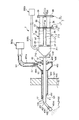
図1は、ノズルの製造方法によって製造されたノズルを有する塗布具の使用状態の一例を示す概略部分縦断面図、図2および図3は、それぞれ、図1に示す塗布具の拡大部分縦断面図、図4および図5は、それぞれ、図1の塗布具におけるノズルの先端側の部分の縦断面図(使用状態を示す図)、図6は、図4中のA−A線断面図、図7は、ノズルの製造方法で用いられるノズル製造用治具の斜視図、図8〜図19は、それぞれ、ノズルの製造方法における各製造工程を順に説明するための縦断面図である。なお、以下では、説明の都合上、図1〜図4、図7〜図19中の右側を「基端(後端)」、左側を「先端」と言う。
Hereinafter, the nozzle manufacturing method of the present invention will be described in detail based on preferred embodiments shown in the accompanying drawings.
FIG. 1 is a schematic partial longitudinal sectional view showing an example of a usage state of an applicator having a nozzle manufactured by a nozzle manufacturing method, and FIG. 2 and FIG. 3 are enlarged partial vertical cross sections of the applicator shown in FIG. 4, FIG. 4 and FIG. 5 are longitudinal sectional views (views showing the use state) of the tip side portion of the nozzle in the applicator of FIG. 1, respectively, and FIG. FIG. 7 is a perspective view of a nozzle manufacturing jig used in the nozzle manufacturing method, and FIGS. 8 to 19 are longitudinal sectional views for sequentially explaining each manufacturing process in the nozzle manufacturing method. In the following, for convenience of explanation, the right side in FIGS. 1 to 4 and 7 to 19 is referred to as “base end (rear end)”, and the left side is referred to as “tip”.

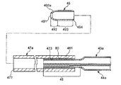
図1に示すように、塗布具1は、例えば腹腔鏡下手術の際に、腹腔500内に挿入して、液組成が異なる2種の液体(第1の液体(第1の流体)L1、第2の液体(第2の流体)L2)を混合しながら、その混合物(混合液)を臓器や腹壁501等に塗布するものである。塗布具1の腹腔500内への挿入は、腹壁501に予め留置されたトロカール管40を介して行われる。具体的には、塗布具1のノズル4をトロカール管40内に挿入して、そのトロカール管40からノズル4のノズルヘッド42を突出させることにより、塗布具1(ノズルヘッド42)を腹腔500内へ挿入することができる。   As shown in FIG. 1, the applicator 1 is inserted into the abdominal cavity 500, for example, during laparoscopic surgery, and two types of liquids (first liquid (first fluid) L1, While mixing the second liquid (second fluid) L2), the mixture (mixed liquid) is applied to the organ, the abdominal wall 501 and the like. The applicator 1 is inserted into the abdominal cavity 500 through the trocar tube 40 previously placed on the abdominal wall 501. Specifically, by inserting the nozzle 4 of the applicator 1 into the trocar tube 40 and projecting the nozzle head 42 of the nozzle 4 from the trocar tube 40, the applicator 1 (nozzle head 42) is placed in the abdominal cavity 500. Can be inserted into.

塗布具1について説明する前に、トロカール管40について説明する。
図1に示すように、トロカール管40は、管状をなす本体部(管状体)401と、本体部401の基端部に設けられたハブ402とを有している。
Before describing the applicator 1, the trocar tube 40 will be described.
As shown in FIG. 1, the trocar tube 40 has a tubular main body portion (tubular body) 401 and a hub 402 provided at the base end portion of the main body portion 401.

本体部401は、その先端および基端が開口したものである。本体部401の先端開口部403は、本体部401の軸に対して傾斜している。これにより、トロカール管40の先端部が、当該トロカール管40を先端側から腹腔500内に挿入するのに容易な形状となる。よって、トロカール管40の腹腔500内への挿入操作を容易に行うことができる。   The main body 401 has an opening at the distal end and the proximal end. The tip opening 403 of the main body 401 is inclined with respect to the axis of the main body 401. As a result, the distal end portion of the trocar tube 40 has an easy shape for inserting the trocar tube 40 into the abdominal cavity 500 from the distal end side. Therefore, the operation of inserting the trocar tube 40 into the abdominal cavity 500 can be easily performed.

ハブ402は、内径および外径が本体部401よりも拡径した部位であり、本体部401内に連通している。   The hub 402 is a portion whose inner diameter and outer diameter are larger than those of the main body 401 and communicates with the main body 401.

ハブ402の外周部には、ガス供給ポート404が突出形成されている。ガス供給ポート404は、チューブ302aを介してガスボンベ(ガス供給手段)300aと接続されている。ガスボンベ300aから供給されたガス(無菌ガス)G1は、チューブ302a、ガス供給ポート404、ハブ402内、本体部401内を順に通過し、腹腔500内に供給される(図1参照)。このガスG1の供給により、腹腔500内の気腹圧(体内圧)が大気圧よりも例えば8〜12mmHg程度上昇して、当該腹腔500が膨張する。これにより、腹腔500は、腹腔鏡下手術を施すのに十分な大きさとなる。なお、ガスボンベ300aは、後述するガスボンベ300bと同様の構成であり、ここでは、その説明を省略する。   A gas supply port 404 protrudes from the outer periphery of the hub 402. The gas supply port 404 is connected to a gas cylinder (gas supply means) 300a through a tube 302a. The gas (sterile gas) G1 supplied from the gas cylinder 300a sequentially passes through the tube 302a, the gas supply port 404, the hub 402, and the main body 401, and is supplied into the abdominal cavity 500 (see FIG. 1). By supplying the gas G1, the abdominal pressure (internal pressure) in the abdominal cavity 500 is increased by, for example, about 8 to 12 mmHg from the atmospheric pressure, and the abdominal cavity 500 is expanded. As a result, the abdominal cavity 500 is large enough to perform laparoscopic surgery. The gas cylinder 300a has the same configuration as a gas cylinder 300b described later, and the description thereof is omitted here.

また、ハブ402の基端開口部405には、当該基端開口部405を覆うようにダックビル弁(弁体)406が設置されている。ダックビル弁406は、塗布具1がトロカール管40に挿入されていない状態では閉口(閉塞)し、塗布具1が挿入されると開口するものである。このダックビル弁406により、塗布具1が挿入された状態でもガスG1が基端開口部405から流出するのを防止することができ、よって、ガスG1が効率よく、確実に腹腔500内に供給される。ダックビル弁406の構成材料としては、特に限定されないが、例えば、天然ゴム、ブチルゴム、イソプレンゴム、ブタジエンゴム、スチレン−ブタジエンゴム、シリコーンゴムのような各種ゴム材料や、ポリウレタン系、ポリエステル系、ポリアミド系、オレフィン系、スチレン系等の各種熱可塑性エラストマー、あるいはそれらの混合物等の弾性材料が挙げられる。   Further, a duckbill valve (valve element) 406 is installed at the base end opening 405 of the hub 402 so as to cover the base end opening 405. The duckbill valve 406 is closed (closed) when the applicator 1 is not inserted into the trocar tube 40 and opens when the applicator 1 is inserted. The duckbill valve 406 can prevent the gas G1 from flowing out of the proximal end opening 405 even when the applicator 1 is inserted. Therefore, the gas G1 is efficiently and reliably supplied into the abdominal cavity 500. The The constituent material of the duckbill valve 406 is not particularly limited. For example, various rubber materials such as natural rubber, butyl rubber, isoprene rubber, butadiene rubber, styrene-butadiene rubber, silicone rubber, polyurethane, polyester, polyamide And elastic materials such as various thermoplastic elastomers such as olefins and styrenes, or mixtures thereof.

また、本体部401およびハブ402は、一体的に形成されていてもよいし、それぞれを別体で構成し、これら別体同士が連結固定されていてもよい。本体部401およびハブ402の構成材料としては、例えば、ポリ塩化ビニル、ポリエチレン、環状ポリオレフィン、ポリスチレン、ポリ−(4−メチルペンテン−1)、ポリカーボネート、アクリル樹脂、アクリルニトリル−ブタジエン−スチレン共重合体、ポリエチレンテレフタレート、ポリエチレンナフタレート等のポリエステル、ブタジエン−スチレン共重合体、ポリアミド(例えば、ナイロン6、ナイロン6・6、ナイロン6・10、ナイロン12)のような各種樹脂が挙げられるが、その中でも、成形が容易であり、かつ水蒸気透過性が低い点で、ポリプロピレン、環状ポリオレフィン、ポリエステルのような樹脂が好ましい。   Moreover, the main-body part 401 and the hub 402 may be integrally formed, each may be comprised by a different body, and these separate bodies may be connected and fixed. Examples of the constituent material of the main body 401 and the hub 402 include polyvinyl chloride, polyethylene, cyclic polyolefin, polystyrene, poly- (4-methylpentene-1), polycarbonate, acrylic resin, and acrylonitrile-butadiene-styrene copolymer. And various resins such as polyesters such as polyethylene terephthalate and polyethylene naphthalate, butadiene-styrene copolymers, and polyamides (for example, nylon 6, nylon 6,6, nylon 6,10, nylon 12). Resins such as polypropylene, cyclic polyolefin, and polyester are preferred because they are easy to mold and have low water vapor permeability.

前述したように、塗布具1は、液組成が異なる2種の液体(第1の液体L1、第2の液体L2)を混合しながら塗布するものである(図1〜図3参照)。塗布具1は、第1の液体L1を収納する第1のシリンジ(液体供給手段)2と、第2の液体L2を収納する第2のシリンジ(液体供給手段)3とをそれぞれ装填して用いられる。第1のシリンジ2と第2のシリンジ3とは、ほぼ同様の構成であるため、代表的に第1のシリンジ2について説明する。   As described above, the applicator 1 applies two liquids (first liquid L1 and second liquid L2) having different liquid compositions while mixing them (see FIGS. 1 to 3). The applicator 1 is used by loading a first syringe (liquid supply means) 2 for storing the first liquid L1 and a second syringe (liquid supply means) 3 for storing the second liquid L2. It is done. Since the 1st syringe 2 and the 2nd syringe 3 are the substantially the same structures, the 1st syringe 2 is demonstrated typically.

第1のシリンジ2は、外筒(シリンジ外筒)21と、外筒21内で摺動し得るガスケット24と、ガスケット24を外筒21の長手方向(軸方向)に沿って移動操作する押し子(プランジャロッド)26とを備えている。ガスケット24は、押し子26の先端に連結されている。   The first syringe 2 includes an outer cylinder (syringe outer cylinder) 21, a gasket 24 that can slide in the outer cylinder 21, and a push that moves the gasket 24 along the longitudinal direction (axial direction) of the outer cylinder 21. A child (plunger rod) 26 is provided. The gasket 24 is connected to the tip of the pusher 26.

外筒21は、有底筒状の部材で構成され、先端側底部の中央部には、外筒21の胴部に対し縮径した縮径部(口部)22が一体的に突出形成されている。   The outer cylinder 21 is composed of a bottomed cylindrical member, and a reduced diameter part (mouth part) 22 that is reduced in diameter relative to the body part of the outer cylinder 21 is integrally formed at the center of the bottom part on the front end side. ing.

外筒21の後端外周には、フランジ23が一体的に形成されている。
また、外筒21の外周面には、液量を示す目盛りが付されている。
A flange 23 is integrally formed on the outer periphery of the rear end of the outer cylinder 21.
A scale indicating the amount of liquid is attached to the outer peripheral surface of the outer cylinder 21.

外筒21の構成材料としては、特に限定されないが、例えば、トロカール管40についての説明で上げたような各種樹脂を用いることができる。なお、外筒21の構成材料は、内部の視認性を確保するために、実質的に透明であるのが好ましい。   The constituent material of the outer cylinder 21 is not particularly limited. For example, various resins as described in the description of the trocar tube 40 can be used. In addition, it is preferable that the constituent material of the outer cylinder 21 is substantially transparent in order to ensure internal visibility.

このような外筒21内には、弾性材料で構成されたガスケット24が収納されて(挿入されて)いる。ガスケット24の外周面が外筒21の内周面に密着しつつ摺動することにより、外筒21内を液密性を確実に保持しつつ、第1の液体L1を口部22に向けて押し出すことができる。ガスケット24の構成材料としては、特に限定されないが、例えば、トロカール管40のダックビル弁406についての説明で挙げたような弾性材料を用いることができる。   In such an outer cylinder 21, a gasket 24 made of an elastic material is accommodated (inserted). By sliding while the outer peripheral surface of the gasket 24 is in close contact with the inner peripheral surface of the outer cylinder 21, the first liquid L1 is directed toward the mouth portion 22 while the liquid tightness is reliably maintained in the outer cylinder 21. Can be extruded. The constituent material of the gasket 24 is not particularly limited, and for example, an elastic material as described in the description of the duckbill valve 406 of the trocar tube 40 can be used.

ガスケット24の移動は、押し子26を移動操作することにより行われる。押し子26は、長尺な部材であり、その基端側には、円盤状のフランジ29が形成されている。また、押し子26の構成材料としては、前述した外筒21と同様のものを用いることができる。   The gasket 24 is moved by operating the pusher 26 to move. The pusher 26 is a long member, and a disc-shaped flange 29 is formed on the base end side thereof. Further, as the constituent material of the pusher 26, the same material as that of the outer cylinder 21 described above can be used.

第1のシリンジ2は、塗布具1に装填される以前に、外筒21とガスケット24とで囲まれた空間(貯液空間)に、第1の液体L1が充填される。第2のシリンジ3には、外筒21とガスケット24とで囲まれた空間(貯液空間)に、第2の液体L2が充填される。   Before the first syringe 2 is loaded into the applicator 1, the space surrounded by the outer cylinder 21 and the gasket 24 (liquid storage space) is filled with the first liquid L1. The second syringe 3 is filled with the second liquid L <b> 2 in a space (liquid storage space) surrounded by the outer cylinder 21 and the gasket 24.

第1のシリンジ2に充填される第1の液体L1と、第2のシリンジ3に充填される第2の液体L2とは、それらの組成(成分)が異なるものである。   The first liquid L1 filled in the first syringe 2 and the second liquid L2 filled in the second syringe 3 have different compositions (components).

第1の液体L1と第2の液体L2とは、塗布具1の用途、使用目的、症例等に応じて適宜選定される。例えば、生体組織接着材の投与に使用する場合、第1の液体L1および第2の液体L2のうちの一方は、トロンビンを含有する液体(溶液等)、他方はフィブリノーゲンを含有する液体(溶液等)とすることができる。   The 1st liquid L1 and the 2nd liquid L2 are suitably selected according to the use of the applicator 1, a purpose of use, a case, etc. For example, when used for administration of a biological tissue adhesive, one of the first liquid L1 and the second liquid L2 is a liquid containing thrombin (solution or the like), and the other is a liquid containing fibrinogen (solution or the like). ).

また、癒着防止材の投与に使用する場合、第1の液体L1および第2の液体L2のうちの一方は、スクシンイミジル基で修飾したカルボキシメチルデキストリンを含有する液体(溶液等)、他方は、リン酸水素二ナトリウムを含有する液体(溶液等)とすることができる。   In addition, when used for administration of the anti-adhesion material, one of the first liquid L1 and the second liquid L2 is a liquid (solution or the like) containing carboxymethyldextrin modified with a succinimidyl group, and the other is phosphorus It can be set as the liquid (solution etc.) containing disodium oxyhydrogen.

このような組み合わせの第1の液体L1および第2の液体L2は、それらを混合すると、変質、すなわち、ゲル化(固化)する。ゲル化することにより、例えば、第1の液体L1と第2の液体L2とが混合したもの(以下、「混合物(混合液)」という場合がある)が、塗布された生体組織(目的部位)に確実に留まることができる。また、混合物が目的部位に確実に留まるため、当該目的部位において、生体組織接着材や癒着防止材としての機能を確実に発揮することができる。   The first liquid L1 and the second liquid L2 in such a combination are altered, that is, gelled (solidified) when they are mixed. By being gelled, for example, a mixture of the first liquid L1 and the second liquid L2 (hereinafter sometimes referred to as “mixture (mixed liquid)”) is applied to a living tissue (target site). You can stay with confidence. In addition, since the mixture remains reliably at the target site, the function as a biological tissue adhesive or an adhesion preventing material can be reliably exhibited at the target site.

なお、第1の液体L1および第2の液体L2の種類および組み合わせは、上述したものに限定されないことは、言うまでもない。また、本実施形態では、第1の液体L1の粘度(粘性)は、第2の液体L2の粘度(粘性)よりも低くなっている。   Needless to say, the types and combinations of the first liquid L1 and the second liquid L2 are not limited to those described above. In the present embodiment, the viscosity (viscosity) of the first liquid L1 is lower than the viscosity (viscosity) of the second liquid L2.

このような構成の第1のシリンジ2および第2のシリンジ3は、後述するノズル4に接続され、各押し子26を押圧操作することより、ノズル4の第1の液体流路44に第1の液体L1を、第2の液体流路45に第2の液体L2を容易かつ確実に供給する(送る)ことができる。また、各押し子26の押圧操作は、塗布具1の操作者(使用者)により手動で行なわれる。このため、操作者は、混合物の塗布を自身の任意のタイミングで行なうことができる。   The 1st syringe 2 and the 2nd syringe 3 of such a structure are connected to the nozzle 4 mentioned later, and the 1st liquid flow path 44 of the nozzle 4 is made into the 1st liquid flow path 44 by pressing each pusher 26. The liquid L1 can be supplied (sent) easily and reliably to the second liquid flow path 45. Moreover, the pressing operation of each pusher 26 is manually performed by an operator (user) of the applicator 1. Therefore, the operator can apply the mixture at his / her arbitrary timing.

また、塗布具1は、第1の液体L1と第2の液体L2とをガスG2とともに噴出するものである(図1〜図3参照)。このガスG2により、前記混合物が霧化され、前記混合物を目的部位(患部等の目標部位)に均一に塗布することができる。ガスG2は、ガスボンベ300bにより供給される。ガスボンベ300bは、チューブ302bを介してノズルと接続されている。   Moreover, the applicator 1 ejects the 1st liquid L1 and the 2nd liquid L2 with gas G2 (refer FIGS. 1-3). The mixture is atomized by the gas G2, and the mixture can be uniformly applied to a target site (target site such as an affected area). The gas G2 is supplied from the gas cylinder 300b. The gas cylinder 300b is connected to the nozzle through the tube 302b.

ガスボンベ300bは、その内部空間に高圧の(圧縮された)無菌ガスG2(以下、単に「ガスG2」と言う)が充填されており、高速に流れるガスG2を塗布具1(ノズル4)に供給する(送る)ことができる。このガスボンベ300bまたはチューブ302bの途中には、塗布具1に対するガスGの供給/供給停止を制御する開閉自在なバルブ(コック)(図示せず)が設置されている。前記混合物を塗布ときには、このバルブを開状態にする。   The gas cylinder 300b is filled with a high-pressure (compressed) sterile gas G2 (hereinafter simply referred to as “gas G2”) in its internal space, and supplies the gas G2 flowing at high speed to the applicator 1 (nozzle 4). You can (send). An openable / closable valve (cock) (not shown) for controlling supply / stop of supply of the gas G to the applicator 1 is installed in the middle of the gas cylinder 300b or the tube 302b. When applying the mixture, the valve is opened.

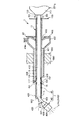
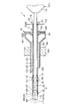
図1〜図3に示すように、塗布具1は、塗布具本体7と、塗布具本体7の先端側に設置された長尺なノズル4と、ノズル4が挿通するシース(外管)11とを備えている。   As shown in FIGS. 1 to 3, the applicator 1 includes an applicator main body 7, a long nozzle 4 installed on the distal end side of the applicator main body 7, and a sheath (outer tube) 11 through which the nozzle 4 is inserted. And.

図1に示すように、塗布具本体7は、第1のシリンジ2の外筒21と第2のシリンジ3の外筒21とを保持するシリンジ保持部71と、第1のシリンジ2の押し子26のフランジ29と第2のシリンジ3の押し子26のフランジ29とを連結するフランジ連結部72とで構成されている。   As shown in FIG. 1, the applicator main body 7 includes a syringe holding portion 71 that holds the outer cylinder 21 of the first syringe 2 and the outer cylinder 21 of the second syringe 3, and a pusher for the first syringe 2. 26 flanges 29 and a flange connecting portion 72 that connects the flange 29 of the pusher 26 of the second syringe 3.

シリンジ保持部71は、第1のシリンジ2(外筒21)および第2のシリンジ3(外筒21)を並べて(並列に)固定するものである。このシリンジ保持部71は、各外筒21の口部22が嵌合する(挿入される)嵌合部711と、嵌合部711よりも基端側に位置し、各外筒21のフランジ23の縁部が挿入される挿入部712と、嵌合部711と挿入部712とを連結する連結部713とを有している。   The syringe holding part 71 fixes the 1st syringe 2 (outer cylinder 21) and the 2nd syringe 3 (outer cylinder 21) side by side (in parallel). The syringe holding part 71 is located on the proximal end side of the fitting part 711 into which the mouth part 22 of each outer cylinder 21 is fitted (inserted) and the fitting part 711, and the flange 23 of each outer cylinder 21. The insertion portion 712 into which the edge portion is inserted, and the connection portion 713 that connects the fitting portion 711 and the insertion portion 712 are included.

嵌合部711に各外筒21の口部22が嵌合すると、第1のシリンジ2の口部22は、ノズル4の第1の液体流路44に接続され、第2のシリンジ3の口部22は、第2の液体流路(液体流路(液体移送路))45に接続される。これにより、第1の液体流路44に第1の液体L1を、第2の液体流路45に第2の液体L2を供給可能となる(図4参照)。   When the mouth portion 22 of each outer cylinder 21 is fitted to the fitting portion 711, the mouth portion 22 of the first syringe 2 is connected to the first liquid flow path 44 of the nozzle 4 and the mouth of the second syringe 3. The unit 22 is connected to a second liquid channel (liquid channel (liquid transfer channel)) 45. As a result, the first liquid L1 can be supplied to the first liquid channel 44, and the second liquid L2 can be supplied to the second liquid channel 45 (see FIG. 4).

また、嵌合部711の外周部には、ガスボンベ300bからのガスG2が通過するチューブ302bの端部が接続される接続部715が突出形成されている。接続部715にチューブ302bが接続されると、当該チューブ302bは、ノズル4のガス流路46に接続される。これにより、ガス流路46にガスG2を供給可能となる(図4参照)。   Further, a connecting portion 715 is formed on the outer peripheral portion of the fitting portion 711 so as to protrude from the end of the tube 302b through which the gas G2 from the gas cylinder 300b passes. When the tube 302 b is connected to the connection portion 715, the tube 302 b is connected to the gas flow path 46 of the nozzle 4. Thereby, gas G2 can be supplied to the gas flow path 46 (refer FIG. 4).

挿入部712には、各外筒21のフランジ23の縁部が挿入される溝714が形成されている。   A groove 714 into which the edge of the flange 23 of each outer cylinder 21 is inserted is formed in the insertion portion 712.

シリンジ保持部71では、嵌合部711に各外筒21の口部22が嵌合し、挿入部712(溝714)に外筒21のフランジ23が挿入されることにより、各外筒21を確実に保持することできる。   In the syringe holding part 71, the mouth part 22 of each outer cylinder 21 is fitted to the fitting part 711, and the flange 23 of the outer cylinder 21 is inserted into the insertion part 712 (groove 714). It can be held securely.

フランジ連結部72は、第1のシリンジ2の押し子26のフランジ29と第2のシリンジ3の押し子26のフランジ29とを連結する板状の部材である。フランジ連結部72には、各押し子26のフランジ29の縁部が挿入される溝721が形成されている。このフランジ連結部72を先端方向に向かって押圧することにより、各押し子26を一括して先端方向に向かって移動させることができる。このように、フランジ連結部72は、塗布具1を使用する、すなわち、混合物を患部等の目標部位に塗布するとき、使用者によって押圧操作される操作部として機能するものである。   The flange connecting portion 72 is a plate-like member that connects the flange 29 of the pusher 26 of the first syringe 2 and the flange 29 of the pusher 26 of the second syringe 3. A groove 721 into which the edge of the flange 29 of each pusher 26 is inserted is formed in the flange connecting portion 72. By pressing the flange connecting portion 72 toward the distal end, the pushers 26 can be moved together toward the distal end. Thus, the flange connection part 72 functions as an operation part that is pressed by the user when the applicator 1 is used, that is, when the mixture is applied to a target site such as an affected part.

シリンジ保持部71およびフランジ連結部72の構成材料としては、例えば、トロカール管40についての説明で上げたような各種樹脂を用いることができる。   As a constituent material of the syringe holding part 71 and the flange connection part 72, for example, various resins as described in the description of the trocar tube 40 can be used.

塗布具本体7の先端側には、ノズル4が設置されている。このノズル4は、ガスG2とともに第1の液体L1、第2の液体L2(混合物)を噴出するものである。   A nozzle 4 is installed on the distal end side of the applicator main body 7. The nozzle 4 ejects the first liquid L1 and the second liquid L2 (mixture) together with the gas G2.

図2〜図4に示すように、ノズル4は、長尺状のノズル本体43と、ノズル本体43の先端側に位置するノズルヘッド42とに分けることができる。   As shown in FIGS. 2 to 4, the nozzle 4 can be divided into an elongated nozzle body 43 and a nozzle head 42 located on the tip side of the nozzle body 43.

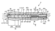
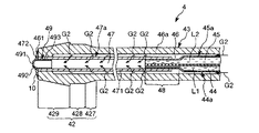
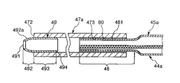
図4に示すように、ノズル4(ノズル本体43)は、第1のシリンジ2からの第1の液体L1が通過する第1の液体流路(第1の液体移送路)44と、第2のシリンジ3からの第2の液体L2が通過する第2の液体流路(第2の液体移送路)45と、各流路を通過した第1の液体流路44と第2の液体L2とが合流する合流部(合流空間)47と、ガスボンベ300bからのガスG2が通過するガス流路46とを有している。   As shown in FIG. 4, the nozzle 4 (nozzle body 43) includes a first liquid flow path (first liquid transfer path) 44 through which the first liquid L1 from the first syringe 2 passes, and a second liquid L1. A second liquid channel (second liquid transfer channel) 45 through which the second liquid L2 from the syringe 3 passes, and a first liquid channel 44 and a second liquid L2 that have passed through each channel. Has a merging part (merging space) 47 and a gas flow path 46 through which the gas G2 from the gas cylinder 300b passes.

第1の液体流路44は、第1のチューブ(第1の流路形成部材)44aで構成されて(形成されて(画成されて))いる。第1のチューブ44aは、その基端部が第1のシリンジ2の口部22に接続される位置まで延在している。   The first liquid channel 44 is configured (formed (defined)) by a first tube (first channel forming member) 44a. The first tube 44 a extends to a position where the base end portion is connected to the mouth portion 22 of the first syringe 2.

第2の液体流路45は、第2のチューブ(第2の流路形成部材)45aで構成されて(形成されて(画成されて))いる。第2のチューブ45aは、その基端部が第2のシリンジ3の口部22に接続される位置まで延在している。   The second liquid channel 45 is configured (formed (defined)) by a second tube (second channel forming member) 45a. The second tube 45 a extends to a position where the base end portion is connected to the mouth portion 22 of the second syringe 3.

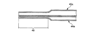
第1のチューブ44aと第2のチューブ45aとは、同じ(同種の)材料で構成され、その材料としては、例えばポリ塩化ビニル、ポリアミド、ポリウレタン、ポリプロピレン、ポリテトラフルオロエチレン、シリコーンゴム、ポリエチレン、ナイロン、エチレン−酢酸ビニル共重合体等のような可撓性を有する材料が挙げられる。これにより、図11〜図13に示すように、ノズル4を製造する過程で、第1のチューブ44aおよび第2のチューブ45aの先端部同士を確実に融着し、これらを一体化することができる。以下、この一体化した部分を「収縮部(一体部)48」と言う。   The first tube 44a and the second tube 45a are made of the same (same type) material, and examples of the material include polyvinyl chloride, polyamide, polyurethane, polypropylene, polytetrafluoroethylene, silicone rubber, polyethylene, Examples thereof include materials having flexibility such as nylon and ethylene-vinyl acetate copolymer. As a result, as shown in FIGS. 11 to 13, in the process of manufacturing the nozzle 4, the distal ends of the first tube 44 a and the second tube 45 a can be reliably fused and integrated. it can. Hereinafter, this integrated part is referred to as a “shrinkage part (integral part) 48”.

図4に示すように、第1のチューブ44aの内径と第2のチューブ45aの内径とは互いに大きさが異なっており、すなわち、第1のチューブ44aの内径は第2のチューブ45aの内径よりも小さくなっており、さらに、収縮部48では、その大小関係が顕著になっている。具体的には、第1のチューブ44aの収縮部48以外の部分の内径は第2のチューブ45aの収縮部48以外の部分の内径の30〜70%となっており、第1のチューブ44aの収縮部48での内径は第2のチューブ45aの収縮部48での内径の10〜50%となっている。   As shown in FIG. 4, the inner diameter of the first tube 44a and the inner diameter of the second tube 45a are different from each other, that is, the inner diameter of the first tube 44a is larger than the inner diameter of the second tube 45a. Furthermore, the size relationship is significant in the contraction portion 48. Specifically, the inner diameter of the portion other than the contraction portion 48 of the first tube 44a is 30 to 70% of the inner diameter of the portion other than the contraction portion 48 of the second tube 45a. The inner diameter at the contraction portion 48 is 10 to 50% of the inner diameter at the contraction portion 48 of the second tube 45a.

これは、前述したように第1の液体L1の粘度(粘性)が第2の液体L2の粘度(粘性)よりも低くなっているので、第1のチューブ44a内を第1の液体L1が通過する際の当該第1の液体L1に対する流路抵抗と、第2のチューブ45a内を第2の液体L2が通過する際の当該第2の液体L2に対する流路抵抗とをほぼ同等とするためである。各液体における流路抵抗が互いに同じとなっていることにより、第1のシリンジ2の押し子26と第2のシリンジ3の押し子26とを連結するフランジ連結部72を押圧した際、例えば一方の押し子26が他方の押し子26よりも移動し難くなる等のような不具合が防止され、その押圧操作を安定して行なうことができる。   As described above, since the viscosity (viscosity) of the first liquid L1 is lower than the viscosity (viscosity) of the second liquid L2, the first liquid L1 passes through the first tube 44a. The flow resistance against the first liquid L1 when the second liquid L2 passes through the second tube 45a and the flow resistance against the second liquid L2 when the second liquid L2 passes through the second tube 45a. is there. When the flow path resistance in each liquid is the same, when the flange connecting portion 72 that connects the pusher 26 of the first syringe 2 and the pusher 26 of the second syringe 3 is pressed, for example, Such a problem that the pusher 26 becomes harder to move than the other pusher 26 is prevented, and the pressing operation can be performed stably.

図4に示すように、第1のチューブ44aと第2のチューブ45aとが一体化した部分である収縮部48は、合流部47を形成する第3のチューブ(合流部形成部材)47aの基端部に接続されている。第3のチューブ47aは、第1のチューブ44aおよび第2のチューブ45aに連通し、第1のチューブ44a内を通過した(流下した)第1の液体L1と、第2のチューブ45a内を通過した(流下した)第2の液体L2とが流入することができる。これにより、第3のチューブ47a(合流部47)内で第1の液体L1と第2の液体L2とが合流し、よって、均一に混合することができる(図4参照)。これにより、混合物を好適な状態(混合が均一な状態)で患部へ塗布することができる。   As shown in FIG. 4, the contraction portion 48, which is a portion where the first tube 44 a and the second tube 45 a are integrated, is a base of the third tube (merging portion forming member) 47 a that forms the merging portion 47. Connected to the end. The third tube 47a communicates with the first tube 44a and the second tube 45a, passes through the first tube 44a (flowed down), and passes through the second tube 45a. The second liquid L2 that has flowed (flowed down) can flow in. As a result, the first liquid L1 and the second liquid L2 merge in the third tube 47a (merging portion 47), and thus can be mixed uniformly (see FIG. 4). Thereby, a mixture can be apply | coated to an affected part in a suitable state (a state with uniform mixing).

また、第3のチューブ47aは、その壁部が通気膜471で構成されたものである。これにより、ガス流路46内のガスG2が通気膜471を介して(透過して)、第3のチューブ47a内に流入する。この流入したガスG2は、混合物とともに、噴出口491から噴出する(図4参照)。これにより、混合物が霧状になり、患部に塗布される。   Further, the wall of the third tube 47a is constituted by a gas permeable membrane 471. Thereby, the gas G2 in the gas flow path 46 flows into (permeates through) the gas permeable membrane 471 and flows into the third tube 47a. This inflowing gas G2 is ejected from the ejection port 491 together with the mixture (see FIG. 4). As a result, the mixture becomes mist and is applied to the affected area.

また、図5に示すように、混合物の噴出が停止した際には、通気膜471を介して流入したガスG2が、第3のチューブ47a内の混合物を確実に外方へ押し出す(吹き飛ばす)。これにより、噴出口491に混合物が残留するのが防止される。よって、当該噴出口491(ノズル4)に目詰まりが生じるのが防止される。   Further, as shown in FIG. 5, when the ejection of the mixture stops, the gas G2 that has flowed in through the gas permeable membrane 471 surely pushes out (blows away) the mixture in the third tube 47a. Thereby, it is prevented that a mixture remains in the jet nozzle 491. Therefore, clogging is prevented from occurring at the ejection port 491 (nozzle 4).

このようなガスG2が透過する通気膜471には、多数の細孔(図示せず)が形成されている。各細孔は、それぞれ通気膜471をその厚さ方向に貫通するものである。これらの細孔の平均孔径は、特に限定されないが、例えば、2μm以下が好ましい。このような細孔を有する通気膜471としては、例えば、住友電工ファインポリマー社製「ポアフロンチューブ(TB−0201)」が挙げられる。これは、平均孔径が約1μmの通気膜471である。   A large number of pores (not shown) are formed in the gas permeable membrane 471 through which such gas G2 permeates. Each pore penetrates the gas permeable membrane 471 in the thickness direction. The average pore diameter of these pores is not particularly limited, but is preferably 2 μm or less, for example. Examples of the air-permeable membrane 471 having such pores include “Pore-Flon tube (TB-0201)” manufactured by Sumitomo Electric Fine Polymer Co., Ltd. This is a gas permeable membrane 471 having an average pore diameter of about 1 μm.

また、孔径を0.01〜0.45μmとすることにより、ガスG2が確実に透過できるとともに、通気膜471が菌不透過性を有することになる。通気膜471が菌不透過性を有することにより、仮にボンベ300b内のガスG2が無菌状態のものでない場合であっても、通気膜471でガスG2内の菌類が除去され、当該菌類が第3のチューブ47a内に流入するのが確実に防止される。これにより、無菌状態の混合物を患部へ塗布することができる。   In addition, by setting the pore diameter to 0.01 to 0.45 μm, the gas G2 can surely permeate, and the gas permeable membrane 471 has a bacteria impermeability. Since the gas permeable membrane 471 is impermeable to bacteria, even if the gas G2 in the cylinder 300b is not in a sterile state, the fungi in the gas G2 are removed by the gas permeable membrane 471, and the fungi are third. It is reliably prevented from flowing into the tube 47a. Thereby, the aseptic mixture can be applied to the affected area.

また、通気膜471の膜厚(壁圧)は、特に限定されず、例えば、0.1〜1mmであるのが好ましく、0.3〜0.8mmであるのがより好ましい。   Moreover, the film thickness (wall pressure) of the ventilation film 471 is not particularly limited, and is preferably 0.1 to 1 mm, and more preferably 0.3 to 0.8 mm, for example.

また、通気膜471の表面積(外周面の面積)は、20〜200mmであるのが好ましく、40〜100mmであるのがより好ましい。 Moreover, it is preferable that the surface area (area of an outer peripheral surface) of the ventilation film 471 is 20-200 mm < 2 >, and it is more preferable that it is 40-100 mm < 2 >.

通気膜471は、第1の液体L1や第2の液体L2に対して不透過性(撥水性)、すなわち、疎水性を有している。これにより、通気膜471を介して、第3のチューブ47a内の混合液がカバーチューブ46a(ガス流路46)内に逆流する(流れ込む)のが確実に防止される。このような通気膜471は、疎水性を有する材料で構成されたもの、または、その表面が疎水化処理が施されたものである。疎水性を有する材料(構成材料)としては、例えば、ポリテトラフルオロエチレン(PTFE)、テトラフルオロエチレンとヘキサフルオロプロピレンの共重合体(FEP)、テトラフルオロエチレンとパーフルオロアルキルビニルエーテルの共重合体(PFA)、ポリクロロトリフルオロエチレン(PCTFE)、ポリフッ化ビニリデン(PVDF)、エチレンとテトラフルオロエチレンの共重合体(ETFE)、エチレンとクロロトリフルオロエチレンの共重合体(ECTFE)、ポリプロピレン(PP)等が挙げられる。通気膜471は、これらの材料を、延伸法、ミクロ相分離法、電子線エッチング法、焼結法、アルゴンプラズマ粒子等の方法で多孔質としたものが好適に用いられる。また、疎水化処理の方法としては、特に限定されず、例えば、通気膜471の表面に、前記疎水性を有する材料(例えばフッ素系樹脂材料)をコーティングする方法等が挙げられる。   The gas permeable membrane 471 is impermeable (water repellency) to the first liquid L1 and the second liquid L2, that is, has hydrophobicity. This reliably prevents the mixed liquid in the third tube 47a from flowing back into (flowing into) the cover tube 46a (gas flow path 46) via the gas permeable membrane 471. Such a gas permeable membrane 471 is made of a hydrophobic material, or the surface thereof is subjected to a hydrophobic treatment. Examples of the hydrophobic material (component material) include polytetrafluoroethylene (PTFE), a copolymer of tetrafluoroethylene and hexafluoropropylene (FEP), and a copolymer of tetrafluoroethylene and perfluoroalkyl vinyl ether ( PFA), polychlorotrifluoroethylene (PCTFE), polyvinylidene fluoride (PVDF), copolymer of ethylene and tetrafluoroethylene (ETFE), copolymer of ethylene and chlorotrifluoroethylene (ECTFE), polypropylene (PP) Etc. As the gas permeable membrane 471, a material obtained by making these materials porous by a stretching method, a microphase separation method, an electron beam etching method, a sintering method, an argon plasma particle, or the like is preferably used. The method for the hydrophobizing treatment is not particularly limited, and examples thereof include a method of coating the surface of the gas permeable membrane 471 with the hydrophobic material (for example, a fluorine resin material).

図4に示すように、第3のチューブ47aの先端部には、噴出口形成部材(ノズルチップ(nozzle tip))49が設置されて(挿入されて)いる。噴出口形成部材49は、筒状体(筒体)で構成され、その先端開口部が、混合液が噴出する液体噴出口491を形成する部材である。   As shown in FIG. 4, an ejection port forming member (nozzle tip) 49 is installed (inserted) at the tip of the third tube 47a. The jet outlet forming member 49 is formed of a cylindrical body (cylinder), and a tip opening portion of the jet outlet forming member 49 forms a liquid jet outlet 491 from which the mixed liquid is jetted.

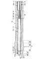
また、図16に示すように、この噴出口形成部材49は、外形が砲弾形状をなしている。すなわち、噴出口形成部材49は、その先端部に設けられたテーパ状をなすテーパ部492と、テーパ部492の基端に設けられた外径一定部493とで構成されている。   Further, as shown in FIG. 16, the jet port forming member 49 has a bullet-shaped outer shape. That is, the ejection port forming member 49 is configured by a tapered portion 492 having a tapered shape provided at the distal end portion thereof, and an outer diameter constant portion 493 provided at the proximal end of the tapered portion 492.

テーパ部492は、その外径が先端方向に向かって漸減した、すなわち、その外周面492aが丸みを帯びた部分である。このテーパ部492は、第3のチューブ47aに固定された(装着された)状態では、第3のチューブ47aの先端(先端面)472から突出している。このようにテーパ部492が突出していることにより、図19に示すように、噴出口形成部材49を第3のチューブ47aに固定する際、当該テーパ部492の外周面492aを、接着剤10を介して第3のチューブ47aの先端472とカバーチューブ46aの先端(先端面)461とに接着するための接着代として用いることができる。また、テーパ部492の外周面492aが丸みを帯びていることにより、ノズル4のノズルヘッド42を腹腔500内に挿入した際に、テーパ部492の外周面492aが臓器や腹壁501等に当接した場合でも、これらの生体組織が外周面492aで損傷を受けるのを確実に防止することができる。また、テーパ部492では、その内径も先端方向に向かって漸減している。これにより、混合物は、噴出口491から噴出する際に確実に霧化する。   The taper portion 492 is a portion where the outer diameter gradually decreases toward the tip, that is, the outer peripheral surface 492a is rounded. The tapered portion 492 protrudes from the tip (tip surface) 472 of the third tube 47a in a state of being fixed (attached) to the third tube 47a. Since the taper portion 492 protrudes in this way, as shown in FIG. 19, when fixing the ejection port forming member 49 to the third tube 47 a, the outer peripheral surface 492 a of the taper portion 492 is attached to the adhesive 10. It can be used as a bonding allowance for bonding to the tip 472 of the third tube 47a and the tip (tip surface) 461 of the cover tube 46a. Since the outer peripheral surface 492a of the tapered portion 492 is rounded, the outer peripheral surface 492a of the tapered portion 492 contacts the organ, the abdominal wall 501 and the like when the nozzle head 42 of the nozzle 4 is inserted into the abdominal cavity 500. Even in this case, these living tissues can be reliably prevented from being damaged at the outer peripheral surface 492a. In addition, the taper portion 492 has an inner diameter that gradually decreases in the distal direction. Thereby, the mixture is reliably atomized when ejected from the ejection port 491.

テーパ部492の基端側に位置する外径一定部493は、その外径が長手方向に沿って一定となった部分である。また、外径一定部493の外径は、第3のチューブ47aの内径とほぼ同等となっている。これにより、外径一定部493を第3のチューブ47aに嵌合する(挿入する)ことができ、よって、この嵌合による固定方法と、前述した接着による固定方法との相乗効果により、第3のチューブ47aに対して噴出口形成部材49をより確実に固定することができる。   The constant outer diameter portion 493 located on the proximal end side of the tapered portion 492 is a portion whose outer diameter is constant along the longitudinal direction. In addition, the outer diameter of the constant outer diameter portion 493 is substantially equal to the inner diameter of the third tube 47a. As a result, the fixed outer diameter portion 493 can be fitted (inserted) into the third tube 47a. Therefore, the synergistic effect of the fixing method by the fitting and the fixing method by the adhesion described above causes the third to occur. The ejection port forming member 49 can be more securely fixed to the tube 47a.

また、噴出口形成部材49の基端面494には、面取り加工が施されている(図16参照)。これにより、噴出口形成部材49をその基端側から第3のチューブ47aに挿入する際の挿入操作を容易に行なうことができる(図16、図17参照)。   Further, the base end surface 494 of the jet port forming member 49 is chamfered (see FIG. 16). Thereby, insertion operation at the time of inserting the spout formation member 49 into the 3rd tube 47a from the base end side can be performed easily (refer FIG. 16, FIG. 17).

噴出口形成部材49は、第3のチューブ47aと異なる硬質の材料(硬質材料)で構成されているのが好ましい。この材料としては、特に限定されないが、例えば、トロカール管40の本体部401やハブ402についての説明で挙げたような樹脂材料やステンレス鋼等のような金属材料を用いることができる。噴出口形成部材49がこのような樹脂材料で構成されている場合には、噴出口形成部材49を第3のチューブ47aに固定する際の固定方法として、前述した接着による方法の他、融着(熱融着、高周波融着、超音波融着等)による方法が可能となる。また、噴出口形成部材49の構成材料としてステンレス鋼のような金属材料を用いた場合、X線透視下でノズル4の先端部の位置確認を補助することができる。   The ejection port forming member 49 is preferably made of a hard material (hard material) different from the third tube 47a. Although it does not specifically limit as this material, For example, metal materials, such as a resin material and stainless steel which were mentioned by description about the main-body part 401 and the hub 402 of the trocar tube 40, can be used. When the jet port forming member 49 is made of such a resin material, as a fixing method when the jet port forming member 49 is fixed to the third tube 47a, in addition to the above-described adhesion method, fusion bonding is performed. It is possible to use a method by (thermal fusion, high frequency fusion, ultrasonic fusion, etc.). Further, when a metal material such as stainless steel is used as the constituent material of the ejection port forming member 49, it is possible to assist the position confirmation of the tip portion of the nozzle 4 under X-ray fluoroscopy.

図4に示すように、ガスG2が通過するガス流路46は、第1の液体流路44および第2の液体流路45をそれぞれ構成する第1のチューブ44aおよび第2のチューブ45aの外周側に位置する、すなわち、第1のチューブ44aおよび第2のチューブ45aが挿通されたカバーチューブ(ガス流路形成部材)46aで構成されている。カバーチューブ46aは、その先端内周部が第3のチューブ47aの先端外周部と嵌合している。また、カバーチューブ46aの先端461と、第3のチューブ47aの先端472とは、ノズル4の長手方向で同じ位置となっている。また、このカバーチューブ46aは、その基端部が塗布具本体7の接続部715を介してチューブ302bに接続される位置まで延在している。   As shown in FIG. 4, the gas flow path 46 through which the gas G2 passes is the outer periphery of the first tube 44a and the second tube 45a constituting the first liquid flow path 44 and the second liquid flow path 45, respectively. That is, it is constituted by a cover tube (gas flow path forming member) 46a through which the first tube 44a and the second tube 45a are inserted. The cover tube 46a has a tip inner peripheral portion fitted to a tip outer peripheral portion of the third tube 47a. Further, the tip 461 of the cover tube 46 a and the tip 472 of the third tube 47 a are at the same position in the longitudinal direction of the nozzle 4. Further, the cover tube 46 a extends to a position where the base end portion is connected to the tube 302 b via the connection portion 715 of the applicator main body 7.

カバーチューブ46aの構成材料としては、特に限定されないが、例えば、第1のチューブ44aや第2のチューブ45aと同様の可撓性を有する材料を用いることができる。   The constituent material of the cover tube 46a is not particularly limited. For example, a material having flexibility similar to that of the first tube 44a and the second tube 45a can be used.

以上のような構成のノズル本体43は、先端部(先端側)に、湾曲または屈曲しており、可撓性(柔軟性)を有する湾曲部431を有している(図1、図2参照)。湾曲部431は、本実施形態では、その先端が斜め下側を向くように、湾曲または屈曲している。この湾曲部431により、ノズルヘッド42の軸線426は、ノズル本体43の軸線(厳密には、ノズル本体43の湾曲部431より基端側の部分432の軸線)433に対して傾斜している(図2参照)。   The nozzle body 43 configured as described above has a curved portion 431 that is curved or bent at the distal end portion (the distal end side) and has flexibility (flexibility) (see FIGS. 1 and 2). ). In the present embodiment, the bending portion 431 is bent or bent so that the tip thereof faces obliquely downward. Due to the curved portion 431, the axis 426 of the nozzle head 42 is inclined with respect to the axis 433 of the nozzle body 43 (strictly, the axis of the portion 432 on the proximal end side of the curved portion 431 of the nozzle body 43) ( (See FIG. 2).

湾曲部431が後述するシース11により規制されることなく湾曲または屈曲した状態のときの、ノズル本体43の軸線433に対するノズルヘッド42の軸線426の傾斜角度θは、30〜90°程度であるのが好ましく、45〜70°程度であるのがより好ましい。   The inclination angle θ of the axis 426 of the nozzle head 42 with respect to the axis 433 of the nozzle body 43 is about 30 to 90 ° when the bending portion 431 is bent or bent without being restricted by the sheath 11 described later. Is preferable, and is preferably about 45 to 70 °.

また、図4に示すように、ノズル本体43の先端側に位置するノズルヘッド42は、外形形状が円柱状をなし、外径が先端方向に向かって漸増する第1テーパ部427と、外径が長手方向(軸線426)に沿って一定の外径一定部428と、外径が先端方向に向かって漸減する第2テーパ部429とが基端側からこの順に配置されたものである。   As shown in FIG. 4, the nozzle head 42 located on the tip side of the nozzle body 43 has a first taper portion 427 whose outer shape is cylindrical and whose outer diameter gradually increases in the tip direction, and an outer diameter. A constant outer diameter constant portion 428 along the longitudinal direction (axis 426) and a second taper portion 429 whose outer diameter gradually decreases in the distal direction are arranged in this order from the base end side.

第1テーパ部427が形成されていることにより、ノズル4が図2に示す状態から図3に示す状態に変化するとき、シース11の先端開口部113の内側の縁部114が第1テーパ部427に沿って、円滑に移動することができる。これにより、ノズルヘッド42をシース11内に確実に導入することができる。なお、縁部114は、丸みを帯びているのが好ましい。これにより、縁部114が第1テーパ部427に沿ってより円滑に移動することができる。   By forming the first taper portion 427, when the nozzle 4 changes from the state shown in FIG. 2 to the state shown in FIG. 3, the edge 114 inside the distal end opening 113 of the sheath 11 is the first taper portion. It can move smoothly along 427. Thereby, the nozzle head 42 can be reliably introduced into the sheath 11. Note that the edge 114 is preferably rounded. Thereby, the edge part 114 can move more smoothly along the 1st taper part 427. FIG.

第1テーパ部427よりも先端側には、第2テーパ部429が位置している。この第2テーパ部429が形成されていることにより、例えば図3に示す状態で塗布具1をトロカール管40に挿入する際、第2テーパ部429がトロカール管40のダックビル弁406を円滑に通過することができる。これにより、塗布具1のトロカール管40への挿入操作を容易に行うことができる。また、第2テーパ部429の基端の外径は、シース11の内径よりも大きい。これにより、ノズルヘッド42がシース11内に入り込んでしまうこと、すなわち、ノズルヘッド42の先端がシース11の先端よりも基端側に移動してしまうのを防止することができる。   The second taper portion 429 is located on the tip side of the first taper portion 427. By forming the second taper portion 429, for example, when the applicator 1 is inserted into the trocar tube 40 in the state shown in FIG. 3, the second taper portion 429 smoothly passes through the duckbill valve 406 of the trocar tube 40. can do. Thereby, insertion operation to the trocar tube 40 of the applicator 1 can be performed easily. Further, the outer diameter of the proximal end of the second tapered portion 429 is larger than the inner diameter of the sheath 11. As a result, the nozzle head 42 can be prevented from entering the sheath 11, that is, the tip of the nozzle head 42 can be prevented from moving closer to the proximal end than the tip of the sheath 11.

第1テーパ部427と第2テーパ部429との間には、外径一定部428が位置している。外径一定部428の外径は、第1テーパ部427の先端の外径(最大外径)と同じであり、また、シース11の内径と同等またはそれよりも若干大きい。これにより、図3に示すように、ノズルヘッド42の軸線426とノズル本体43の軸線433とが一致する際に、外径一定部428(第1テーパ部427の先端も含む)がシース11の先端開口部113に入り込んで嵌合する。よって、ノズルヘッド42の軸線426とノズル本体43の軸線433とが一致した状態を維持することができる。また、この維持された状態のまま混合物を腹腔500内の目的部位に塗布することができる。塗布具1では、外径一定部428と第1テーパ部427の先端(一部)とをシース11の先端開口部113と嵌合する「嵌合部」ということができる。   A constant outer diameter portion 428 is located between the first tapered portion 427 and the second tapered portion 429. The outer diameter of the constant outer diameter portion 428 is the same as the outer diameter (maximum outer diameter) of the tip of the first taper portion 427 and is equal to or slightly larger than the inner diameter of the sheath 11. As a result, as shown in FIG. 3, when the axis 426 of the nozzle head 42 and the axis 433 of the nozzle main body 43 coincide with each other, the constant outer diameter portion 428 (including the tip of the first taper portion 427) It enters and fits into the tip opening 113. Therefore, it is possible to maintain a state where the axis 426 of the nozzle head 42 and the axis 433 of the nozzle main body 43 coincide. In addition, the mixture can be applied to the target site in the abdominal cavity 500 in this maintained state. In the applicator 1, the constant outer diameter portion 428 and the tip (part) of the first taper portion 427 can be referred to as a “fitting portion” that fits with the tip opening 113 of the sheath 11.

図2(図1、図3も同様)に示すように、塗布具1は、ノズル本体43の湾曲部431の形状を規制する形状規制部材としての機能を有するシース11を有している。このシース11は、その先端および基端がそれぞれ開口した長尺状の管体で構成されており、その内部には、ノズル4(ノズル本体43)が挿通し(挿入され)ている。本実施形態では、シース11は、湾曲部431よりも先端側の部分(ノズルヘッド42の外径一定部428)からノズル本体43の基端部の近傍まで挿入されるようになっている。また、シース11は、ノズル本体43に対し、ノズル本体43の長手方向(軸方向)に沿って移動可能になっている。   As shown in FIG. 2 (the same applies to FIGS. 1 and 3), the applicator 1 has a sheath 11 having a function as a shape regulating member that regulates the shape of the curved portion 431 of the nozzle body 43. The sheath 11 is composed of a long tubular body whose distal end and proximal end are opened, and a nozzle 4 (nozzle body 43) is inserted (inserted) into the sheath 11. In the present embodiment, the sheath 11 is inserted from the distal end portion (the constant outer diameter portion 428 of the nozzle head 42) to the vicinity of the proximal end portion of the nozzle main body 43 relative to the curved portion 431. The sheath 11 is movable with respect to the nozzle body 43 along the longitudinal direction (axial direction) of the nozzle body 43.

このシース11は、湾曲部431の一部または全部を覆ったときに当該湾曲部431の形状を規制し(矯正し)得るように、硬質材料で構成されており、必要かつ十分な剛性を有し、さらには低摺動性を有していることが望ましい。   The sheath 11 is made of a hard material so that the shape of the bending portion 431 can be regulated (corrected) when part or all of the bending portion 431 is covered, and has a necessary and sufficient rigidity. Furthermore, it is desirable that it has low slidability.

シース11の構成材料としては、例えば、ポリエチレン、ポリプロピレン等のポリオレフィン樹脂、ポリテトラフルオロエチレン等のフッ素樹脂、ポリカーボネート、ポリエチレンテレフタレート、ポリアミド等の硬質樹脂、ステンレス鋼、アルミニウム、銅または銅系合金等の各種金属材料、各種ガラス、アルミナ、シリカ等の各種セラミックスが挙げられる。   Examples of the constituent material of the sheath 11 include polyolefin resins such as polyethylene and polypropylene, fluorine resins such as polytetrafluoroethylene, hard resins such as polycarbonate, polyethylene terephthalate, and polyamide, stainless steel, aluminum, copper, and copper alloys. Various ceramic materials such as various metal materials, various glasses, alumina, silica and the like can be mentioned.

前述したように、シース11をノズル本体43の長手方向に沿って移動操作することができる。この移動操作により、シース11内に湾曲部431が挿入されて、シース11の先端からの湾曲部431の突出長を調整し、その湾曲部431の形状を矯正する(変更する)ことができる(図2、図3参照)。これにより、ノズル本体43の軸線433に対するノズルヘッド42の軸線426の傾斜角度θ(ノズルヘッド42の方向)を調整することができる。換言すれば、シース11は、図3に示すように、湾曲部431がシース11により矯正(規制)されて直線状となり、ノズルヘッド42の軸線426の方向とノズル本体43の軸線433の方向とが一致する第1の位置(傾斜角度θ=0°)と、図2に示すように、湾曲部431がシース11により規制されることなく湾曲または屈曲した状態となり、ノズル本体43の軸線433がノズルヘッド42の軸線426に対して傾斜する第2の位置(傾斜角度θが最大傾斜角度)との間で移動し得るようになっている。これにより、シース11を第1の位置と第2の位置との間の所定の位置に移動させることで、傾斜角度θを0°から最大傾斜角度までの範囲内で自在に調整することができる。   As described above, the sheath 11 can be moved along the longitudinal direction of the nozzle body 43. By this moving operation, the bending portion 431 is inserted into the sheath 11, the protrusion length of the bending portion 431 from the distal end of the sheath 11 is adjusted, and the shape of the bending portion 431 can be corrected (changed) ( (See FIGS. 2 and 3). Thereby, the inclination angle θ (direction of the nozzle head 42) of the axis 426 of the nozzle head 42 with respect to the axis 433 of the nozzle body 43 can be adjusted. In other words, as shown in FIG. 3, the sheath 11 is straightened by the curved portion 431 being corrected (restricted) by the sheath 11, and the direction of the axis 426 of the nozzle head 42 and the direction of the axis 433 of the nozzle body 43. 2 and the first position (inclination angle θ = 0 °), and as shown in FIG. 2, the bending portion 431 is bent or bent without being restricted by the sheath 11, and the axis 433 of the nozzle body 43 is The nozzle head 42 can move between a second position inclined with respect to the axis 426 of the nozzle head 42 (the inclination angle θ is the maximum inclination angle). Thereby, the inclination angle θ can be freely adjusted within the range from 0 ° to the maximum inclination angle by moving the sheath 11 to a predetermined position between the first position and the second position. .

このように、シース11を移動してこの傾斜角度θを適宜調整することによってノズルヘッド42の傾斜角度θを変えつつ、当該ノズルヘッド42から混合物を腹腔500内の複数の箇所(例えば臓器や腹壁501)に向けて噴霧することができる。従って、塗布具1は、腹腔500内で混合物を容易かつ確実に広範囲にわたって塗布することができるものである。なお、塗布具1では、外力が付与されていない自然状態での湾曲部431の湾曲の程度(傾斜角度θ)を適宜設定することにより(例えば「U」字状)、塗布具1の生体への挿入方向に位置する臓器に対向する腹壁501の裏面(裏側)にも混合物を塗布することができる。   In this way, by moving the sheath 11 and appropriately adjusting the inclination angle θ, the inclination angle θ of the nozzle head 42 is changed, and the mixture is transferred from the nozzle head 42 to a plurality of locations in the abdominal cavity 500 (for example, organs and abdominal walls). 501). Therefore, the applicator 1 can apply the mixture easily and reliably over a wide range within the abdominal cavity 500. In the applicator 1, by appropriately setting the degree of bending (inclination angle θ) of the bending portion 431 in a natural state where no external force is applied (for example, “U” shape), the applicator 1 can be applied to the living body. The mixture can also be applied to the back surface (back side) of the abdominal wall 501 facing the organ located in the insertion direction.

また、シース11には、その基端外周部に、板状のフランジ(突部)115が突出形成されている。このフランジ115を把持して、シース11の長手方向に沿って移動操作することにより、当該シース11を移動させることができる。このように、フランジ115は、シース11を移動させる際の操作部として機能する。   The sheath 11 is formed with a plate-like flange (projection) 115 projecting from the outer peripheral portion of the base end thereof. The sheath 11 can be moved by gripping the flange 115 and moving it along the longitudinal direction of the sheath 11. Thus, the flange 115 functions as an operation unit when the sheath 11 is moved.

前述したように、塗布具1は、トロカール管40に挿入した状態で用いられる。この状態で、塗布具1を先端方向に押圧していくと、シース11のフランジ115がハブ402の基端開口部405(基端部)に当接することとなる。これにより、シース11のトロカール管40に対する先端方向への移動限界を規制することができ、よって、シース11の基端部がトロカール管40内に不本意に入り込んでしまうこと、すなわち、シース11の基端部がトロカール管40の基端開口部405よりも先端側に移動してしまうのを防止することができる。これにより、シース11の基端部(一部)がトロカール管40の基端開口部405から確実に突出して、その突出した部分を把持することができる。よって、シース11を移動操作することができる。このように、フランジ115は、シース11のトロカール管40に対する先端方向への移動限界を規制する規制手段としても機能する。   As described above, the applicator 1 is used while being inserted into the trocar tube 40. When the applicator 1 is pressed in the distal direction in this state, the flange 115 of the sheath 11 comes into contact with the proximal end opening 405 (base end) of the hub 402. As a result, the limit of movement of the sheath 11 in the distal direction relative to the trocar tube 40 can be restricted, and accordingly, the proximal end portion of the sheath 11 can be inadvertently introduced into the trocar tube 40, that is, the sheath 11. It is possible to prevent the proximal end portion from moving toward the distal end side with respect to the proximal end opening 405 of the trocar tube 40. Thereby, the base end part (part) of the sheath 11 protrudes reliably from the base end opening 405 of the trocar tube 40, and the protruding part can be gripped. Therefore, the sheath 11 can be moved. Thus, the flange 115 also functions as a restricting means for restricting the movement limit of the sheath 11 in the distal direction relative to the trocar tube 40.

なお、前記傾斜角度θを調整する操作と、第1の液体L1および第2の液体L2を吐出(噴出)する操作とは、どのような順番でも行うこともできる。   The operation for adjusting the tilt angle θ and the operation for ejecting (jetting) the first liquid L1 and the second liquid L2 can be performed in any order.

すなわち、傾斜角度θを調整する操作と、第1の液体L1および第2の液体L2を噴出する操作とを同時に行ってもよく、また、第1の液体L1および第2の液体L2を噴出する操作を先に開始し、その後、傾斜角度θを調整する操作を行ってもよい。これらの場合は、それぞれ、第1の液体L1および第2の液体L2の噴出を開始した後、傾斜角度θの調整により、塗布を行う範囲を広げることができる。また、傾斜角度θを調整する操作を先に行って、その後、第1の液体L1および第2の液体L2を噴出する操作を行ってもよい。   That is, the operation for adjusting the tilt angle θ and the operation for ejecting the first liquid L1 and the second liquid L2 may be performed simultaneously, and the first liquid L1 and the second liquid L2 are ejected. The operation may be started first, and then the operation for adjusting the tilt angle θ may be performed. In these cases, after starting the ejection of the first liquid L1 and the second liquid L2, the range of application can be expanded by adjusting the inclination angle θ. Alternatively, the operation of adjusting the inclination angle θ may be performed first, and then the operation of ejecting the first liquid L1 and the second liquid L2 may be performed.

また、図2、図3に示すように、シース11とノズル4との間には、間隙15が形成されている。この間隙15は、シース11(ノズル4)の長手方向に沿って、すなわち、シース11の先端開口部113から基端開口部116にわたって形成されている。   As shown in FIGS. 2 and 3, a gap 15 is formed between the sheath 11 and the nozzle 4. The gap 15 is formed along the longitudinal direction of the sheath 11 (nozzle 4), that is, from the distal end opening 113 to the proximal end opening 116 of the sheath 11.

また、シース11には、先端開口部113よりも基端側に、壁部を貫通する2つの側孔117が形成されている。これらの側孔117は、シース11の長手方向に関して同じ位置に、シース11の軸を介して対向配置されている。各側孔117は、間隙15に連通しており、腹腔500内のガスG3が間隙15内に流入する流入口(ガスG3を取り入れる取入れ口)として機能する(図2、図3参照)。なお、側孔117の形成数は、2つに限定されず、例えば、1つまたは3つ以上であってもよい。   The sheath 11 has two side holes 117 penetrating the wall portion on the proximal end side with respect to the distal end opening portion 113. These side holes 117 are arranged opposite to each other through the axis of the sheath 11 at the same position in the longitudinal direction of the sheath 11. Each side hole 117 communicates with the gap 15 and functions as an inflow port (an intake port for taking in the gas G3) through which the gas G3 in the abdominal cavity 500 flows into the gap 15 (see FIGS. 2 and 3). Note that the number of side holes 117 formed is not limited to two, and may be one or three or more, for example.

このような間隙15は、腹腔500内のガス(気体)G3を体外へ排出する排気路として機能する。以下、これについて説明する。   Such a gap 15 functions as an exhaust path for discharging the gas (gas) G3 in the abdominal cavity 500 to the outside of the body. This will be described below.

図1に示すように、腹腔500内には、トロカール管40からガスG1が噴出し、塗布具1(ノズルヘッド42)から混合物とともにガスG2が噴出する。前述したように、ガスG1によって、腹腔500内の気腹圧が上昇して当該腹腔500が膨張する。また、腹腔500内の気腹圧は、ガスG2によっても上昇してしまい、これによって、当該腹腔500がさらに膨張しようとする。しかしながら、腹腔500内のガスG3(ガスG1、G2を含む)は、各側孔117を介して、間隙15内に流入する(図2、図3参照)。そして、ガスG3は、間隙15内を流下し、基端開口部116から排出される(図2、図3参照)。これにより、腹腔500内の気腹圧の過剰な上昇を抑制(または防止)することができ、腹腔500がさらに膨張しようとするのを防止することができる。   As shown in FIG. 1, the gas G1 is ejected from the trocar tube 40 into the abdominal cavity 500, and the gas G2 is ejected together with the mixture from the applicator 1 (nozzle head 42). As described above, the gas G1 increases the abdominal pressure in the abdominal cavity 500, and the abdominal cavity 500 expands. In addition, the pneumoperitoneum pressure in the abdominal cavity 500 is also increased by the gas G2, which causes the abdominal cavity 500 to further expand. However, the gas G3 (including gases G1 and G2) in the abdominal cavity 500 flows into the gap 15 through the side holes 117 (see FIGS. 2 and 3). Then, the gas G3 flows down in the gap 15 and is discharged from the proximal end opening 116 (see FIGS. 2 and 3). This can suppress (or prevent) an excessive increase in the pneumoperitoneum pressure in the abdominal cavity 500 and prevent the abdominal cavity 500 from further expanding.

また、前述したように、塗布具1は、腹腔500内で混合物を容易かつ確実に広範囲にわたって塗布することができるよう構成されたものである。腹腔500内で混合物が広範囲にわたって塗布されるため、当該混合物の噴出量も多くなり、これに伴ってガスG2の噴出量も多くなる。多量のガスG2が噴出されると腹腔500内の気腹圧が上昇しそうになるが、前記間隙の排気作用により、その上昇を抑えることができる。このように、塗布具1は、腹腔500内で混合物を広範囲にわたって塗布する場合にも有効である。   Further, as described above, the applicator 1 is configured so that the mixture can be easily and reliably applied over a wide range within the abdominal cavity 500. Since the mixture is applied over a wide range within the abdominal cavity 500, the ejection amount of the mixture increases, and the ejection amount of the gas G2 also increases accordingly. When a large amount of gas G2 is ejected, the pneumoperitoneum pressure in the abdominal cavity 500 is likely to increase, but the increase can be suppressed by the exhaust action of the gap. Thus, the applicator 1 is also effective when applying the mixture over a wide range within the abdominal cavity 500.

間隙15の途中には、ノズル4の外周方向に沿ったリング状のスペーサ(弾性体)16が設置されている(図2、図3参照)。このスペーサ16は、その外周面がシース11の内周面118に固定され、内周面がノズル本体43の外周面435に当接している。スペーサ16の内周面は、シース11が移動したときにノズル本体43の外周面435を摺動し、ノズル本体43の外周面435とスペーサ16の内周面との間に摩擦抵抗が生じる。   In the middle of the gap 15, a ring-shaped spacer (elastic body) 16 is installed along the outer peripheral direction of the nozzle 4 (see FIGS. 2 and 3). The outer peripheral surface of the spacer 16 is fixed to the inner peripheral surface 118 of the sheath 11, and the inner peripheral surface is in contact with the outer peripheral surface 435 of the nozzle body 43. The inner peripheral surface of the spacer 16 slides on the outer peripheral surface 435 of the nozzle main body 43 when the sheath 11 moves, and a frictional resistance is generated between the outer peripheral surface 435 of the nozzle main body 43 and the inner peripheral surface of the spacer 16.

このような構成のスペーサ16は、シース11を移動して停止させた際、その停止位置でシース11のノズル4の長手方向に対する位置決めを行う位置決め手段として機能する。これにより、ノズルヘッド42の傾斜角度θを維持することができ、この状態のまま混合物を噴出することができる。   The spacer 16 having such a configuration functions as positioning means for positioning the sheath 11 in the longitudinal direction of the nozzle 4 at the stop position when the sheath 11 is moved and stopped. Thereby, the inclination angle θ of the nozzle head 42 can be maintained, and the mixture can be ejected in this state.

また、スペーサ16は、シース11の内周面118とノズル本体43の外周面435との間で圧縮された状態で設置されている。これにより、スペーサ16は、その径方向には変形し難いものとなり、間隙15の間隙距離(ギャップ長)を規制する(維持する)機能も発揮する。これにより、シース11の内周面118とノズル本体43の外周面435とが接して、間隙15(排気路)の途中が閉塞するのを確実に防止することができ、ガスG3を間隙15を介してより確実に排気することができる。   The spacer 16 is installed in a compressed state between the inner peripheral surface 118 of the sheath 11 and the outer peripheral surface 435 of the nozzle body 43. Thereby, the spacer 16 becomes difficult to deform in the radial direction, and also exhibits a function of regulating (maintaining) the gap distance (gap length) of the gap 15. As a result, the inner peripheral surface 118 of the sheath 11 and the outer peripheral surface 435 of the nozzle body 43 are in contact with each other, so that it is possible to reliably prevent the gap 15 (exhaust passage) from being blocked. It is possible to exhaust more reliably.

図2に示すように、スペーサ16は、各側孔117よりも先端側に配置されている。この位置でスペーサ16は、間隙15をその途中で封止している。また、図3に示す状態では、ノズルヘッド42によってシース11の先端開口部113が塞がれてしまうが、各側孔117からは、ガスG3が間隙15内に入り込むので、そのガスG3を確実に排気することができる。   As shown in FIG. 2, the spacer 16 is disposed on the tip side of each side hole 117. At this position, the spacer 16 seals the gap 15 in the middle. In the state shown in FIG. 3, the tip opening 113 of the sheath 11 is blocked by the nozzle head 42, but the gas G <b> 3 enters the gap 15 from each side hole 117. Can be exhausted.

スペーサ16の構成材料としては、特に限定されず、例えば、ダックビル弁406についての説明で挙げたような各種弾性材料を用いることができる。   The constituent material of the spacer 16 is not particularly limited, and for example, various elastic materials as mentioned in the description of the duckbill valve 406 can be used.

以上のような構成の塗布具1のノズル4は、本発明の製造方法(ノズルの製造方法)によって製造されている。以下、この製造方法について説明するが、その前に、当該製造方法で用いるノズル製造用治具(以下単に「治具」と言う)20について説明する。   The nozzle 4 of the applicator 1 configured as described above is manufactured by the manufacturing method (manufacturing method of the nozzle) of the present invention. Hereinafter, this manufacturing method will be described, but before that, a nozzle manufacturing jig (hereinafter simply referred to as “jig”) 20 used in the manufacturing method will be described.

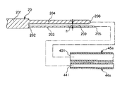
図7に示す治具20は、ノズル4を製造する際に用いられるものである。この治具20は、長尺な治具本体201と、治具本体201の基端面202(基端部)に突出形成された第1の挿入部(第1のマンドレル)203および第2の挿入部(第2のマンドレル)204とを備えている。   The jig 20 shown in FIG. 7 is used when the nozzle 4 is manufactured. The jig 20 includes a long jig body 201, a first insertion portion (first mandrel) 203 formed on the base end surface 202 (base end portion) of the jig body 201, and a second insertion. Part (second mandrel) 204.

治具本体201は、円柱状をなし、治具20を使用する際に把持される把持部として機能する。   The jig body 201 has a cylindrical shape and functions as a gripping part that is gripped when the jig 20 is used.

第1の挿入部203は、棒状をなし、第1のチューブ44a内に挿入される部位である(図9参照)。この第1の挿入部203の外径は、第1のチューブ44aに収縮部48が形成される前の第1のチューブ44aの内径よりも小さく、かつ、第1のチューブ44aに収縮部48が形成された際のその収縮部48での第1のチューブ44aの内径と同等である。また、第1の挿入部203の端面205は、丸みを帯びている(図8参照)。これにより、第1の挿入部203を第1のチューブ44aに挿入する際の挿入操作を容易に行なうことができる。   The first insertion portion 203 has a rod shape and is a portion that is inserted into the first tube 44a (see FIG. 9). The outer diameter of the first insertion portion 203 is smaller than the inner diameter of the first tube 44a before the contraction portion 48 is formed on the first tube 44a, and the contraction portion 48 is present on the first tube 44a. It is equivalent to the inner diameter of the first tube 44a at the contracted portion 48 when formed. Further, the end face 205 of the first insertion portion 203 is rounded (see FIG. 8). Thereby, the insertion operation at the time of inserting the 1st insertion part 203 in the 1st tube 44a can be performed easily.

第2の挿入部204は、棒状をなし、第1の挿入部203と平行に配置されている。この第2の挿入部204は、第2のチューブ45a内に挿入される部位である(図9参照)。第2の挿入部204の外径は、第2のチューブ45aに収縮部48が形成される前の第2のチューブ45aの内径よりも小さく、かつ、第2のチューブ45aに収縮部48が形成された際のその収縮部48での第2のチューブ45aの内径と同等である。また、第2の挿入部204の端面206は、丸みを帯びている(図8参照)。これにより、第2の挿入部204を第2のチューブ45aに挿入する際の挿入操作を容易に行なうことができる。   The second insertion portion 204 has a rod shape and is arranged in parallel with the first insertion portion 203. This 2nd insertion part 204 is a site | part inserted in the 2nd tube 45a (refer FIG. 9). The outer diameter of the second insertion portion 204 is smaller than the inner diameter of the second tube 45a before the contraction portion 48 is formed on the second tube 45a, and the contraction portion 48 is formed on the second tube 45a. This is equivalent to the inner diameter of the second tube 45a at the contracted portion 48 when it is formed. Further, the end face 206 of the second insertion portion 204 is rounded (see FIG. 8). Thereby, the insertion operation at the time of inserting the 2nd insertion part 204 in the 2nd tube 45a can be performed easily.

また、第2の挿入部204は、その長さが第1の挿入部203の長さよりも短い。治具20では、第1の挿入部203と第2の挿入部204との外径同士を比較して、細い方の挿入部には細い方のチューブを確実に挿入し、太い方の挿入部には太い方のチューブを確実に挿入することができることの他、第1の挿入部203と第2の挿入部204との長さ同士を比較しても、細長い方の挿入部には細い方のチューブを確実に挿入し、残った方(他方)の挿入部には太い方のチューブを確実に挿入することができる。このように誤挿入を確実に防止することができる。また、比較的挿入困難な細い方のチューブを先に挿入することができるよう、第1の挿入部203を長くし、挿入容易な太い方のチューブを後に挿入するよう、第2の挿入部204を短くすることで、両チューブを円滑に挿入することができる。   The length of the second insertion portion 204 is shorter than the length of the first insertion portion 203. In the jig 20, the outer diameters of the first insertion portion 203 and the second insertion portion 204 are compared with each other, and the thinner tube is securely inserted into the thinner insertion portion, and the thicker insertion portion is inserted. In addition to being able to securely insert the thicker tube, even if the lengths of the first insertion portion 203 and the second insertion portion 204 are compared, the narrower insertion portion This tube can be securely inserted, and the thicker tube can be reliably inserted into the remaining (other) insertion portion. In this way, erroneous insertion can be reliably prevented. In addition, the first insertion portion 203 is lengthened so that the thinner tube, which is relatively difficult to insert, can be inserted first, and the second insertion portion 204 is inserted so that the thicker tube, which is easy to insert, can be inserted later. By shortening, both tubes can be inserted smoothly.

第1の挿入部203の外径と第2の挿入部204の外径と間隙209における間隙距離(ギャップ長)hとの総和は、合流部47の内径よりも小さく設定されている。これにより、一体化した収縮部48に形成される2つの流路は、収縮部48を合流部に嵌合したときに閉塞するのが確実に防止される。   The sum of the outer diameter of the first insertion portion 203, the outer diameter of the second insertion portion 204, and the gap distance (gap length) h in the gap 209 is set to be smaller than the inner diameter of the merge portion 47. Thereby, it is reliably prevented that the two flow paths formed in the integrated contraction part 48 are closed when the contraction part 48 is fitted to the merge part.

なお、治具20の構成材料としては、特に限定されないが、例えば、ステンレス鋼等のような金属材料を用いることができる。また、治具20は、治具本体201と第1の挿入部203と第2の挿入部204とが一体的に形成されたものであってもよいし、治具本体201と第1の挿入部203と第2の挿入部204とをそれぞれ別体で構成し、これらを連結した(接合した)ものであってもよい。   In addition, although it does not specifically limit as a constituent material of the jig | tool 20, For example, metal materials, such as stainless steel, can be used. Further, the jig 20 may be one in which the jig main body 201, the first insertion portion 203, and the second insertion portion 204 are integrally formed, or the jig main body 201 and the first insertion portion. The part 203 and the second insertion part 204 may be configured separately and connected (joined) to each other.

次に、ノズル4を製造する製造方法について、図8〜図19を参照しつつ説明する。
この製造方法は、治具装着工程と、収縮部形成工程(一体部形成工程)と、熱収縮チューブ除去工程と、治具抜去工程と、チューブ連結工程と、噴出口装着工程と、カバーチューブ装着工程と、接着剤塗布工程とを有している。
Next, a manufacturing method for manufacturing the nozzle 4 will be described with reference to FIGS.
This manufacturing method includes a jig mounting process, a contracted part forming process (integral part forming process), a heat shrink tube removing process, a jig removing process, a tube connecting process, a spout mounting process, and a cover tube mounting. A process and an adhesive application process.

[1]治具装着工程
図8に示すように、治具20を用意する。その他、第1のチューブ44aおよび第2のチューブ45aを用意する。
[1] Jig Mounting Process As shown in FIG. 8, a jig 20 is prepared. In addition, a first tube 44a and a second tube 45a are prepared.

また、治具20をその第1の挿入部203、第2の挿入部204を基端側に向け、各挿入部にそれぞれ対応するように第1のチューブ44aおよび第2のチューブ45aを配置する。   Also, the first tube 44a and the second tube 45a are arranged so as to correspond to the respective insertion portions with the jig 20 facing the first insertion portion 203 and the second insertion portion 204 toward the proximal end side. .

そして、図8に示す状態から第1の挿入部203を第1のチューブ44aの先端部に挿入するとともに、第2の挿入部204を第2のチューブ45aの先端部に挿入する。これにより、図9に示すように、第1の挿入部203が第1のチューブ44aに挿入し、第2の挿入部204が第2のチューブ45aに挿入した挿入状態となる。この挿入状態では、第1のチューブ44aの先端441と第2のチューブ45aの先端451とは、それぞれ、治具20の治具本体201の基端面202から離間している。また、先端441、451同士は、チューブ長手方向に関して同じ位置となっている。   Then, from the state shown in FIG. 8, the first insertion portion 203 is inserted into the distal end portion of the first tube 44a, and the second insertion portion 204 is inserted into the distal end portion of the second tube 45a. Thereby, as shown in FIG. 9, the first insertion portion 203 is inserted into the first tube 44a, and the second insertion portion 204 is inserted into the second tube 45a. In this inserted state, the distal end 441 of the first tube 44a and the distal end 451 of the second tube 45a are separated from the base end surface 202 of the jig body 201 of the jig 20, respectively. The tips 441 and 451 are at the same position in the tube longitudinal direction.

[2]収縮部形成工程
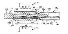
次に、図9に示す挿入状態の第1のチューブ44aの先端部と第2のチューブ45aの先端部とを、熱収縮チューブ60に挿入する。これにより、図10に示すように、熱収縮チューブ60で各チューブの先端部を一括して覆うことができる。
[2] Shrinkage forming step Next, the tip of the first tube 44a and the tip of the second tube 45a in the inserted state shown in FIG. Thereby, as shown in FIG. 10, the front-end | tip part of each tube can be collectively covered with the heat contraction tube 60. FIG.

ここで用いる熱収縮チューブ60とは、熱収縮性を有する材料で構成されたチューブである。このような材料としては、特に限定されないが、例えば、シリコーン系樹脂、ポリエチレンが挙げられる。また、熱収縮チューブ60を構成する材料(樹脂材料)は、第1のチューブ44aおよび第2のチューブ45aを構成する材料(樹脂材料)と異なるのが好ましい。例えば、第1のチューブ44aおよび第2のチューブ45aがそれぞれウレタン系樹脂で構成されている場合には、熱収縮チューブ60をウレタン系樹脂よりも融点が高いシリコーン系樹脂で構成することができる。後述するようにヒータ70で加熱した際(図11参照)、熱収縮チューブ60が溶融する前に第1のチューブ44aおよび第2のチューブ45aが溶融するため、第1のチューブ44aおよび第2のチューブ45aの先端部同士が融着する。また、熱収縮チューブ60は、熱により収縮するため、第1のチューブ44aおよび第2のチューブ45aの先端部同士を締め付けることとなる。これにより、第1のチューブ44aおよび第2のチューブ45aの先端部同士の融着が確実に行なわれる。また、熱収縮チューブ60は、溶融しないため、第1のチューブ44aおよび第2のチューブ45aの先端部を締め付けても、各チューブと一体化するのが防止される。これにより、以降の工程で熱収縮チューブ60を第1のチューブ44aおよび第2のチューブ45aから容易に除去(剥離)することができる(図12参照)。   The heat shrinkable tube 60 used here is a tube made of a material having heat shrinkability. Such a material is not particularly limited, and examples thereof include silicone resins and polyethylene. Moreover, it is preferable that the material (resin material) which comprises the heat contraction tube 60 differs from the material (resin material) which comprises the 1st tube 44a and the 2nd tube 45a. For example, when the first tube 44a and the second tube 45a are each made of a urethane resin, the heat-shrinkable tube 60 can be made of a silicone resin having a higher melting point than the urethane resin. As described later, when heated by the heater 70 (see FIG. 11), the first tube 44a and the second tube 45a are melted before the heat shrinkable tube 60 is melted. The tips of the tubes 45a are fused together. Moreover, since the heat-shrinkable tube 60 shrinks due to heat, the distal ends of the first tube 44a and the second tube 45a are fastened together. Thereby, fusion | melting of the front-end | tip parts of the 1st tube 44a and the 2nd tube 45a is performed reliably. Further, since the heat shrinkable tube 60 does not melt, even if the distal ends of the first tube 44a and the second tube 45a are tightened, they are prevented from being integrated with each tube. Thereby, the heat shrinkable tube 60 can be easily removed (peeled) from the first tube 44a and the second tube 45a in the subsequent steps (see FIG. 12).

そして、図11に示すように、熱収縮チューブ60で覆われた部分を当該熱収縮チューブ60ごとヒータ70で加熱する。これにより、熱収縮チューブ60が収縮(縮径)し、この収縮した熱収縮チューブ60によって、第1のチューブ44aおよび第2のチューブ45aの各先端部が締め付けられて収縮変形するとともに、これら先端部同士が融着する。これにより、第1のチューブ44aおよび第2のチューブ45aの先端部同士が一体となった収縮部48を形成することができる。なお、収縮部48の収縮の程度(外径)は、加熱前の第1のチューブ44aの外径と第2のチューブ45aの外径との和よりも小さくなっている。   Then, as shown in FIG. 11, the portion covered with the heat shrinkable tube 60 is heated by the heater 70 together with the heat shrinkable tube 60. As a result, the heat-shrinkable tube 60 is contracted (diametered), and the contracted and deformed portions of the first tube 44a and the second tube 45a are tightened and contracted by the contracted heat-shrinkable tube 60. The parts are fused together. Thereby, the shrinkage | contraction part 48 with which the front-end | tip parts of the 1st tube 44a and the 2nd tube 45a were united can be formed. The degree of contraction (outer diameter) of the contraction section 48 is smaller than the sum of the outer diameter of the first tube 44a and the outer diameter of the second tube 45a before heating.

また、ヒータ70で加熱した際、第1のチューブ44aの先端部をその内周面442全周が治具20の第1の挿入部203の外周面207に密着するまで、すなわち、第1のチューブ44aの先端部の内腔をその内径が第1の挿入部203の外径と同等となるように維持しつつ、収縮変形させる。これと同様に、第2のチューブ45aの先端部もその内周面452全周が第2の挿入部204の外周面208に密着するまで、すなわち、第2のチューブ45aの先端部の内腔をその内径が第2の挿入部204の外径と同等となるように維持しつつ、収縮変形させる。これにより、第1のチューブ44aおよび第2のチューブ45aの各先端部がそれぞれ過不足なく収縮した収縮部48を形成することができる。   Further, when heated by the heater 70, the tip of the first tube 44 a is in contact with the outer peripheral surface 207 of the first insertion portion 203 of the jig 20 until the entire inner peripheral surface 442 thereof is in close contact with the first tube 44 a, that is, the first tube 44 a. The lumen of the distal end portion of the tube 44a is contracted and deformed while maintaining the inner diameter thereof to be equal to the outer diameter of the first insertion portion 203. Similarly, the distal end portion of the second tube 45a is also in contact with the outer peripheral surface 208 of the second insertion portion 204, ie, the lumen of the distal end portion of the second tube 45a. Is contracted and deformed while maintaining the inner diameter to be equal to the outer diameter of the second insertion portion 204. Thereby, the contraction part 48 which each front-end | tip part of the 1st tube 44a and the 2nd tube 45a contracted without excess and deficiency can respectively be formed.

このように形成された収縮部48は、その横断面形状が円形となっている(図6参照)。この収縮部48の外径は、第3のチューブ47aの内径と同等またはそれよりも若干小さい。このように収縮部48がその横断面形状が円形であることにより、以降の工程で収縮部48を第3のチューブ47aを挿入する際(図16参照)、その挿入操作を容易に行なうことができ、また、収縮部48と第3のチューブ47aとが確実に嵌合する。   The contracted portion 48 thus formed has a circular cross-sectional shape (see FIG. 6). The outer diameter of the contraction portion 48 is equal to or slightly smaller than the inner diameter of the third tube 47a. Thus, when the contraction part 48 has a circular cross-sectional shape, when the third tube 47a is inserted into the contraction part 48 in the subsequent steps (see FIG. 16), the insertion operation can be easily performed. Moreover, the contraction part 48 and the 3rd tube 47a fit reliably.

なお、図10に示すように、加熱される前の熱収縮チューブ60の内径は、第1のチューブ44aの内径と第2のチューブ45aの内径との総和よりも大きい。これにより、熱収縮チューブ60に、第1のチューブ44aと第2のチューブ45aとを容易に一括して挿入することができる。   As shown in FIG. 10, the inner diameter of the heat-shrinkable tube 60 before being heated is larger than the sum of the inner diameter of the first tube 44a and the inner diameter of the second tube 45a. Accordingly, the first tube 44a and the second tube 45a can be easily and collectively inserted into the heat shrinkable tube 60.

また、図10に示す状態では、熱収縮チューブ60の先端601は、第1のチューブ44aの先端441と第2のチューブ45aの先端451よりも先端側に位置している。これにより、熱収縮チューブ60が収縮した際、その収縮力によって各先端441、451をそれぞれ確実に収縮変形させることができる(図11参照)。   In the state shown in FIG. 10, the tip 601 of the heat-shrinkable tube 60 is located on the tip side of the tip 441 of the first tube 44a and the tip 451 of the second tube 45a. Thereby, when the heat-shrinkable tube 60 contracts, each of the tips 441 and 451 can be reliably contracted and deformed by the contraction force (see FIG. 11).

また、熱収縮チューブ60の基端602は、第1の挿入部203および第2の挿入部204の長手方向の途中に位置している、すなわち、熱収縮チューブ60の長さは、治具20の第1の挿入部203および第2の挿入部204の長さよりも短くなっている。これにより、熱収縮チューブ60を第1の挿入部203(第2の挿入部204についても同様)の長手方向の途中に位置させることができる。そして、この状態で熱収縮チューブ60が収縮した際、その収縮力によって、第1のチューブ44aの収縮部48を形成するのに必要な部分を確実に収縮変形させることができる(第2のチューブ45aについても同様)。   In addition, the base end 602 of the heat shrinkable tube 60 is located in the middle of the first insertion portion 203 and the second insertion portion 204 in the longitudinal direction, that is, the length of the heat shrinkable tube 60 is determined by the jig 20. This is shorter than the length of the first insertion portion 203 and the second insertion portion 204. Thereby, the heat-shrinkable tube 60 can be located in the middle of the longitudinal direction of the 1st insertion part 203 (same also about the 2nd insertion part 204). When the heat-shrinkable tube 60 contracts in this state, the contraction force can reliably contract and deform a portion necessary for forming the contracting portion 48 of the first tube 44a (second tube). The same applies to 45a).

[3]熱収縮チューブ除去工程
次に、図12に示すように、前記収縮した熱収縮チューブ60を収縮部48から除去する、すなわち、前記収縮した熱収縮チューブ60から収縮部48を抜去する。前述したように熱収縮チューブ60を加熱しても当該熱収縮チューブ60が第1のチューブ44aおよび第2のチューブ45aと一体化するのが防止されているため、この除去操作(除去作業)を容易に行なうことができる。
[3] Heat Shrinkable Tube Removal Step Next, as shown in FIG. 12, the contracted heat shrinkable tube 60 is removed from the contracted portion 48, that is, the contracted portion 48 is removed from the contracted heat shrinkable tube 60. As described above, even if the heat-shrinkable tube 60 is heated, the heat-shrinkable tube 60 is prevented from being integrated with the first tube 44a and the second tube 45a. It can be done easily.

[4]治具抜去工程
次に、図13に示すように、挿入状態の収縮部48から治具20の第1の挿入部203および第2の挿入部204を抜去する。
[4] Jig Removal Step Next, as shown in FIG. 13, the first insertion portion 203 and the second insertion portion 204 of the jig 20 are removed from the contracted portion 48 in the inserted state.

[5]チューブ連結工程
次に、図14に示すように、第3のチューブ47aの基端側と収縮部48の先端側とを対向させる。そして、図15に示すように、第3のチューブ47aの基端部に収縮部48の一部または全部を挿入する。これにより、第3のチューブ47aの基端部に収縮部48が確実に嵌合し、よって、第1のチューブ44aおよび第2のチューブ45aと第3のチューブ47aとが確実に連結する。
[5] Tube Connection Step Next, as shown in FIG. 14, the proximal end side of the third tube 47 a and the distal end side of the contracting portion 48 are opposed to each other. And as shown in FIG. 15, a part or all of the shrinkage | contraction part 48 is inserted in the base end part of the 3rd tube 47a. As a result, the contraction portion 48 is securely fitted to the proximal end portion of the third tube 47a, so that the first tube 44a, the second tube 45a, and the third tube 47a are reliably connected.

また、第3のチューブ47aの外径は、加熱前の第1のチューブ44aの外径、すなわち、第1のチューブ44aの収縮部48以外の部分の外径と、加熱前の第2のチューブ45aの外径、すなわち、第2のチューブ45aの収縮部48以外の部分の外径との和とほぼ同等となっている(例えば図4参照)。これにより、カバーチューブ46a内でのデッドスペースが生じるのを抑制することができ、よって、カバーチューブ46aが太くなるのを防止することができる、すなわち、ノズル4の細径化に寄与する。   Further, the outer diameter of the third tube 47a is the outer diameter of the first tube 44a before heating, that is, the outer diameter of the portion other than the contraction portion 48 of the first tube 44a, and the second tube before heating. It is substantially the same as the sum of the outer diameter of 45a, that is, the outer diameter of the portion of the second tube 45a other than the contracting portion 48 (see, for example, FIG. 4). Thereby, it is possible to suppress the occurrence of a dead space in the cover tube 46a, and thus it is possible to prevent the cover tube 46a from becoming thick, that is, to contribute to a reduction in the diameter of the nozzle 4.

また、図14に示すように、第3のチューブ47aの基端部に収縮部48を挿入する際に、収縮部48の外周面(外周部)481の一部に接着剤80を例えば接着剤塗布具90を用いて塗布する。そして、第3のチューブ47aをその軸回りに回転しつつ、収縮部48の挿入操作を行なう。これにより、第3のチューブ47aの基端部の内周面(内周部)473と収縮部48の外周面481との間に接着剤80が付与される。この接着剤80を介して第3のチューブ47aの基端部と収縮部48とが接着し、よって、第1のチューブ44aおよび第2のチューブ45aと第3のチューブ47aとがより確実に連結する。なお、接着剤80は、図14示す構成では収縮部48の外周面481に塗布されているが、これに限定されず、第3のチューブ47aの基端部の内周面473に塗布されていてもよい。また、接着剤80は、後述する接着剤10と同様(同種)のものを用いることができる。   Moreover, as shown in FIG. 14, when inserting the shrinkage | contraction part 48 in the base end part of the 3rd tube 47a, the adhesive agent 80 is used for a part of outer peripheral surface (outer peripheral part) 481 of the shrinkage | contraction part 48, for example, an adhesive agent Application is performed using an applicator 90. Then, the contraction section 48 is inserted while rotating the third tube 47a about its axis. As a result, the adhesive 80 is applied between the inner peripheral surface (inner peripheral portion) 473 of the proximal end portion of the third tube 47 a and the outer peripheral surface 481 of the contraction portion 48. The proximal end portion of the third tube 47a and the contracted portion 48 are bonded to each other through the adhesive 80, so that the first tube 44a, the second tube 45a, and the third tube 47a are more reliably connected. To do. In the configuration shown in FIG. 14, the adhesive 80 is applied to the outer peripheral surface 481 of the contraction portion 48, but is not limited thereto, and is applied to the inner peripheral surface 473 of the base end portion of the third tube 47 a. May be. Moreover, the adhesive 80 can use the same thing (same kind) as the adhesive 10 mentioned later.

[6]噴出口装着工程
次に、図16に示すように、噴出口形成部材49の基端側と第3のチューブ47aの先端側とを対向させる。そして、図17に示すように、第3のチューブ47aの先端部に、噴出口形成部材49をその途中、すなわち、テーパ部492と外径一定部493との境界部まで挿入する。これにより、第3のチューブ47aの先端部にその内径とほぼ同等の噴出口形成部材49の外径一定部493が嵌合し、よって、噴出口形成部材49を第3のチューブ47aに装着することができる。
[6] Jetting Port Mounting Step Next, as shown in FIG. 16, the base end side of the jetting port forming member 49 and the tip end side of the third tube 47a are opposed to each other. Then, as shown in FIG. 17, the ejection port forming member 49 is inserted in the middle of the distal end portion of the third tube 47 a, that is, to the boundary portion between the tapered portion 492 and the constant outer diameter portion 493. As a result, the outer diameter constant portion 493 of the jet port forming member 49 that is substantially equal to the inner diameter of the third tube 47a is fitted, so that the jet port forming member 49 is attached to the third tube 47a. be able to.

また、このとき、噴出口形成部材49のテーパ部492(先端部)は、第3のチューブ47aの先端472から突出した突出状態となっている。この突出したテーパ部492の外周面492aは、後述する接着剤塗布工程では、接着剤10を介して第3のチューブ47aの先端472とカバーチューブ46aの先端461とに噴出口形成部材49を接着するための接着代として用いられる。   At this time, the tapered portion 492 (tip portion) of the ejection port forming member 49 is in a protruding state protruding from the tip 472 of the third tube 47a. The protruding outer peripheral surface 492a of the tapered portion 492 adheres the spout forming member 49 to the tip 472 of the third tube 47a and the tip 461 of the cover tube 46a via the adhesive 10 in the adhesive application step described later. It is used as a bonding allowance for

[7]カバーチューブ装着工程
次に、図18に示すように、前記噴出口装着工程で得られた部材をカバーチューブ46a内に挿入する。これにより、カバーチューブ46aが装着される。
[7] Cover Tube Mounting Step Next, as shown in FIG. 18, the member obtained in the jet port mounting step is inserted into the cover tube 46a. Thereby, the cover tube 46a is attached.

また、カバーチューブ46aの先端461と第3のチューブ47aの先端472とは、チューブ長手方向に関して同じ位置となっている。   The tip 461 of the cover tube 46a and the tip 472 of the third tube 47a are at the same position in the tube longitudinal direction.

[8]接着剤塗布工程
次に、図19に示すように、接着剤塗布具90を用いて、噴出口形成部材49の接着代としてのテーパ部492の外周面492aと、第3のチューブ47aの先端472と、カバーチューブ46aの先端461とに接着剤10を塗布する(付与する)。この接着剤10が硬化すると、その接着剤10を介して噴出口形成部材49が第3のチューブ47aおよびカバーチューブ46aに対して確実に固定される。これにより、ノズル4を得る。
[8] Adhesive Application Step Next, as shown in FIG. 19, using the adhesive applicator 90, the outer peripheral surface 492 a of the tapered portion 492 serving as the bonding allowance of the spout formation member 49 and the third tube 47 a. The adhesive 10 is applied (applied) to the tip 472 and the tip 461 of the cover tube 46a. When the adhesive 10 is cured, the jet forming member 49 is securely fixed to the third tube 47a and the cover tube 46a via the adhesive 10. Thereby, the nozzle 4 is obtained.

また、接着剤10は、硬化した際にその厚さが外方(図19中上下方向)に向かって漸減している。これにより、テーパ部492の第3のチューブ47aの先端472からの突出分を緩和することができる。これにより、例えば、ノズル4のノズルヘッド42が腹腔500内に挿入されたとき、当該ノズル4の先端周辺が生体組織に接触してもその部分で生体組織が損傷するのが確実に防止される。   Further, when the adhesive 10 is cured, its thickness gradually decreases outward (in the vertical direction in FIG. 19). Thereby, the protrusion part from the front-end | tip 472 of the 3rd tube 47a of the taper part 492 can be relieve | moderated. Thereby, for example, when the nozzle head 42 of the nozzle 4 is inserted into the abdominal cavity 500, even if the periphery of the tip of the nozzle 4 comes into contact with the living tissue, the living tissue is reliably prevented from being damaged at that portion. .

また、この硬化した接着剤10の最大厚さは、噴出口形成部材49のテーパ部492の突出量よりも小さい。これにより、テーパ部492の最先端のみが突出した形状となるため、合流液(混合液)がノズル先端から液垂れしても、テーパ部492の最先端に合流液が留まりづらく、目詰まりが起こりにくい。   Further, the maximum thickness of the cured adhesive 10 is smaller than the protruding amount of the tapered portion 492 of the jet forming member 49. As a result, since only the leading edge of the tapered portion 492 protrudes, even if the merged liquid (mixed liquid) drips from the tip of the nozzle, the merged liquid does not stay at the leading edge of the tapered portion 492, and clogging occurs. Hard to happen.

また、接着剤80は、特に限定されず、例えば、シリコーン系、エポキシ系、アクリル系、シアノアクリレート系、ポリウレタン系等の、紫外線硬化型、可視光硬化型、または電子線硬化型の接着剤を好適に用いることができ、これらの中でも特にシアノアクリレート系が好ましい。   The adhesive 80 is not particularly limited. For example, an ultraviolet curable, visible light curable, or electron beam curable adhesive such as silicone, epoxy, acrylic, cyanoacrylate, polyurethane, or the like is used. Of these, cyanoacrylates are particularly preferred.

また、接着代の長さ、すなわち、第3のチューブ47aの先端472(カバーチューブ46aの先端461)から突出するテーパ部492の突出量は、噴出口形成部材49外径の10〜70%であるのが好ましく、30〜50%であるのがより好ましい。これにより、噴出口形成部材49に接着剤10を塗布するのに必要な塗布面積を十分に確保することができ、よって、接着剤10を介して、噴出口形成部材49を第3のチューブ47aに対して確実に固定することができる。また、突出した噴出口形成部材49が生体に接触した際に傷害を与えるのを防止または抑制することができる。   Further, the length of the bonding margin, that is, the protruding amount of the tapered portion 492 protruding from the tip 472 of the third tube 47a (tip 461 of the cover tube 46a) is 10 to 70% of the outer diameter of the jet forming member 49. It is preferred that it is 30 to 50%. Thereby, it is possible to sufficiently secure an application area necessary for applying the adhesive 10 to the jet forming member 49. Accordingly, the jet forming member 49 is connected to the third tube 47a via the adhesive 10. It can be securely fixed against. In addition, it is possible to prevent or suppress damage to the protruding jet forming member 49 when it comes into contact with the living body.

また、テーパ部492の外周面492aは、前述したように丸みを帯びている(テーパ状をなっている)ため、例えば側面視で直線状となっている場合に比べて接着剤10との接着面積が多くなり、よって、接着強度が高まる。   Further, since the outer peripheral surface 492a of the tapered portion 492 is rounded (has a tapered shape) as described above, for example, it is bonded to the adhesive 10 as compared with a case where it is linear in a side view. The area increases, thus increasing the adhesive strength.

また、テーパ部492の外周面492aには、接着剤10との親和性を付与する表面処理が施されていてもよい。この表面処理としては、特に限定されず、例えば、粗面化処理等が挙げられる。テーパ部492の外周面492aが粗面化されている場合、外周面492aが平滑な場合に比べて、接着剤10の外周面492aに対する接着強度が高まる。   Further, the outer peripheral surface 492a of the tapered portion 492 may be subjected to a surface treatment that imparts affinity with the adhesive 10. The surface treatment is not particularly limited, and examples thereof include a roughening treatment. When the outer peripheral surface 492a of the taper part 492 is roughened, the adhesive strength of the adhesive 10 with respect to the outer peripheral surface 492a is increased as compared with the case where the outer peripheral surface 492a is smooth.

以上のような製造方法により、ノズル4(塗布具1)が第3のチューブ47aで構成された合流部47を有するものとなる。これにより、合流部47で第1の液体L1と第2の液体L2とが確実に混合することができ、この混合物をノズル4から噴出することができる。   By the manufacturing method as described above, the nozzle 4 (applicator 1) has the joining portion 47 constituted by the third tube 47a. Thereby, the 1st liquid L1 and the 2nd liquid L2 can be mixed reliably in the junction part 47, and this mixture can be ejected from the nozzle 4. FIG.

また、混合物の噴出口が1つとなるため、ノズル4全体としての太さを抑えることができる、すなわち、ノズル4の細径化に有利となる。これにより、ノズル4を体腔内に容易かつ確実に挿入することができる。   In addition, since the mixture has one jet outlet, the overall thickness of the nozzle 4 can be suppressed, that is, it is advantageous for reducing the diameter of the nozzle 4. Thereby, the nozzle 4 can be easily and reliably inserted into the body cavity.

また、接着剤10は噴出口形成部材49と第3のチューブ47aとの間に介在しないため、ノズル4の太さが太くなるのが防止され、よって、ノズル4の細径化に有利となる。   Further, since the adhesive 10 is not interposed between the ejection port forming member 49 and the third tube 47a, it is possible to prevent the nozzle 4 from becoming thicker, which is advantageous for reducing the diameter of the nozzle 4. .

また、第1の液体L1が通過する第1の液体流路44では、その流路径が絞られている箇所は、第1のチューブ44aの収縮部48となっている。これと同様に、第2の液体L2が通過する第2の液体流路45でも、その流路径が絞られている箇所は、第2のチューブ45aの収縮部48となっている。また、第1の液体L1と第2の液体L2とが通過する合流部47では、その流路径が絞られている箇所は、噴出口形成部材49内となっている。このような構成により、ノズル4から混合物を噴出しているときにノズル4内で圧力損失が生じるのは、主に収縮部48内や噴出口形成部材49内となり、よって、ノズル4全体としての圧力損失を抑制することができる。   Further, in the first liquid channel 44 through which the first liquid L1 passes, the portion where the channel diameter is narrowed is the contraction part 48 of the first tube 44a. Similarly, also in the second liquid channel 45 through which the second liquid L2 passes, the portion where the channel diameter is narrowed is the contraction part 48 of the second tube 45a. Further, in the merge portion 47 through which the first liquid L1 and the second liquid L2 pass, the portion where the flow path diameter is narrowed is in the jet forming member 49. With such a configuration, when the mixture is ejected from the nozzle 4, pressure loss occurs in the nozzle 4 mainly in the contraction portion 48 and the ejection port forming member 49. Pressure loss can be suppressed.

以上、本発明のノズルの製造方法を図示の実施形態について説明したが、本発明は、これに限定されるものではなく、ノズルの製造方法を構成する各工程は、同様の操作を行なう任意の工程のものと置換することができる。また、任意の工程が付加されていてもよい。   As mentioned above, although the manufacturing method of the nozzle of this invention was demonstrated about embodiment of illustration, this invention is not limited to this, Each process which comprises the manufacturing method of a nozzle is arbitrary which performs the same operation. It can be replaced with that of the process. Moreover, arbitrary processes may be added.

また、塗布具は、腹腔内に挿入して用いることができるが、これに限定されず、例えば、胸腔内、子宮内等のような体腔内にも挿入して用いることができる。   The applicator can be used by being inserted into the abdominal cavity, but is not limited thereto, and can be used by being inserted into a body cavity such as a thoracic cavity or a uterus.

また、塗布具は、トロカール管から腹腔内にガスを供給して該腹腔を膨張させるような手技に用いられるが、これに限定されず、例えば、腹壁を吊り下げて腹腔の大きさを確保する手技、いわゆる吊り下げ法に用いることもできる。   In addition, the applicator is used for a procedure for inflating the abdominal cavity by supplying gas into the abdominal cavity from the trocar tube. However, the applicator is not limited thereto. It can also be used for procedures, so-called suspension methods.

また、腹腔鏡下でトロカール管が複数腹壁に留置されて(穿刺されて)いる場合には、これらのトロカール管のうち、例えば1つのトロカール管からガスが供給され、その他のトロカール管からはガスの供給が停止していることもある。   In addition, when a plurality of trocar tubes are placed (punctured) in the abdominal wall under the laparoscope, gas is supplied from, for example, one trocar tube among these trocar tubes, and gas is supplied from the other trocar tubes. Supply may be stopped.

また、ノズル製造用治具は、第1の挿入部と第2の挿入部との長さが異なっているが、第1の挿入部と第2の挿入部との長さ同じであってもよい。   In the nozzle manufacturing jig, the lengths of the first insertion portion and the second insertion portion are different, but the lengths of the first insertion portion and the second insertion portion are the same. Good.

また、ノズルの第1のチューブおよび第2のチューブを通過するものは、それぞれ、液体であるのに限定されず、例えば、一方のチューブを通過するものは、液体であり、他方のチューブを通過するものは、気体であってもよい。   Moreover, what passes through the first tube and the second tube of the nozzle is not limited to being a liquid. For example, what passes through one tube is a liquid and passes through the other tube. The thing to do may be a gas.

ノズルの製造方法によって製造されたノズルを有する塗布具の使用状態の一例を示す概略部分縦断面図である。It is a general | schematic fragmentary longitudinal cross-section which shows an example of the use condition of the applicator which has the nozzle manufactured by the manufacturing method of a nozzle. 図1に示す塗布具の拡大部分縦断面図である。It is an expanded partial longitudinal cross-sectional view of the applicator shown in FIG. 図1に示す塗布具の拡大部分縦断面図である。It is an expanded partial longitudinal cross-sectional view of the applicator shown in FIG. 図1の塗布具におけるノズルの先端側の部分の縦断面図(使用状態を示す図)である。It is a longitudinal cross-sectional view (figure which shows a use condition) of the part at the front end side of the nozzle in the applicator of FIG. 図1の塗布具におけるノズルの先端側の部分の縦断面図(使用状態を示す図)である。It is a longitudinal cross-sectional view (figure which shows a use condition) of the part at the front end side of the nozzle in the applicator of FIG. 図4中のA−A線断面図である。It is the sectional view on the AA line in FIG. ノズルの製造方法で用いられるノズル製造用治具の斜視図である。It is a perspective view of the jig for nozzle manufacture used with the manufacturing method of a nozzle. ノズルの製造方法における各製造工程を順に説明するための縦断面図である。It is a longitudinal cross-sectional view for demonstrating in order each manufacturing process in the manufacturing method of a nozzle. ノズルの製造方法における各製造工程を順に説明するための縦断面図である。It is a longitudinal cross-sectional view for demonstrating in order each manufacturing process in the manufacturing method of a nozzle. ノズルの製造方法における各製造工程を順に説明するための縦断面図である。It is a longitudinal cross-sectional view for demonstrating in order each manufacturing process in the manufacturing method of a nozzle. ノズルの製造方法における各製造工程を順に説明するための縦断面図である。It is a longitudinal cross-sectional view for demonstrating in order each manufacturing process in the manufacturing method of a nozzle. ノズルの製造方法における各製造工程を順に説明するための縦断面図である。It is a longitudinal cross-sectional view for demonstrating in order each manufacturing process in the manufacturing method of a nozzle. ノズルの製造方法における各製造工程を順に説明するための縦断面図である。It is a longitudinal cross-sectional view for demonstrating in order each manufacturing process in the manufacturing method of a nozzle. ノズルの製造方法における各製造工程を順に説明するための縦断面図である。It is a longitudinal cross-sectional view for demonstrating in order each manufacturing process in the manufacturing method of a nozzle. ノズルの製造方法における各製造工程を順に説明するための縦断面図である。It is a longitudinal cross-sectional view for demonstrating in order each manufacturing process in the manufacturing method of a nozzle. ノズルの製造方法における各製造工程を順に説明するための縦断面図である。It is a longitudinal cross-sectional view for demonstrating in order each manufacturing process in the manufacturing method of a nozzle. ノズルの製造方法における各製造工程を順に説明するための縦断面図である。It is a longitudinal cross-sectional view for demonstrating in order each manufacturing process in the manufacturing method of a nozzle. ノズルの製造方法における各製造工程を順に説明するための縦断面図である。It is a longitudinal cross-sectional view for demonstrating in order each manufacturing process in the manufacturing method of a nozzle. ノズルの製造方法における各製造工程を順に説明するための縦断面図である。It is a longitudinal cross-sectional view for demonstrating in order each manufacturing process in the manufacturing method of a nozzle.

符号の説明Explanation of symbols

1 塗布具
2 第1のシリンジ(液体供給手段)
21 外筒
22 縮径部(口部)
23 フランジ
24 ガスケット
26 押し子(プランジャロッド)
29 フランジ
3 第2のシリンジ(液体供給手段)
4 ノズル
42 ノズルヘッド
426 軸線
427 第1テーパ部
428 外径一定部
429 第2テーパ部
43 ノズル本体
431 湾曲部
432 湾曲部より基端側の部分
433 軸線
435 外周面
44 第1の液体流路(第1の液体移送路)
44a 第1のチューブ(第1の流路形成部材)
441 先端
442 内周面
45 第2の液体流路(第2の液体移送路)
45a 第2のチューブ(第2の流路形成部材)
451 先端
452 内周面
46 ガス流路
46a カバーチューブ(ガス流路形成部材)
461 先端
47 合流部(合流空間)
47a 第3のチューブ(合流部形成部材)
471 通気膜
472 先端
473 内周面(内周部)
48 収縮部(一体部)
481 外周面(外周部)
49 噴出口形成部材
491 噴出口
492 テーパ部
492a 外周面
493 外径一定部
494 基端面
7 塗布具本体
71 シリンジ保持部
711 嵌合部
712 挿入部
713 連結部
714 溝
715 接続部
72 フランジ連結部
721 溝
10 接着剤
11 シース(外管)
113 先端開口部
114 縁部
115 フランジ(突部)
116 基端開口部
117 側孔
118 内周面
15 間隙
16 スペーサ(弾性体)
20 ノズル製造用治具(治具)
201 治具本体
202 基端面
203 第1の挿入部(第1のマンドレル)
204 第2の挿入部(第2のマンドレル)
205、206 端面
207、208 外周面
209 間隙
300a、300b ガスボンベ(ガス供給手段)
302a、302b チューブ
40 トロカール管
401 本体部(管状体)
402 ハブ
403 先端開口部
404 ガス供給ポート
405 基端開口部
406 ダックビル弁(弁体)
500 腹腔
501 腹壁
60 熱収縮チューブ
601 先端
602 基端
70 ヒータ
80 接着剤
90 接着剤塗布具
G1、G2 ガス(無菌ガス)
G3 ガス(気体)
L1 第1の液体(第2の流体)
L2 第2の液体(第2の流体)
h 間隙距離(ギャップ長)
θ 傾斜角度
DESCRIPTION OF SYMBOLS 1 Applicator 2 1st syringe (liquid supply means)
21 outer cylinder 22 reduced diameter part (mouth)
23 Flange 24 Gasket 26 Pusher (plunger rod)
29 Flange 3 Second syringe (liquid supply means)
DESCRIPTION OF SYMBOLS 4 Nozzle 42 Nozzle head 426 Axis 427 1st taper part 428 Outer diameter constant part 429 2nd taper part 43 Nozzle main body 431 Bending part 432 A part of a base end side from a bending part 433 Axis line 435 Outer peripheral surface 44 1st liquid flow path ( First liquid transfer path)
44a First tube (first flow path forming member)
441 Tip 442 Inner peripheral surface 45 Second liquid flow path (second liquid transfer path)
45a Second tube (second flow path forming member)
451 tip 452 inner peripheral surface 46 gas flow path 46a cover tube (gas flow path forming member)
461 Tip 47 Merging section (merging space)
47a Third tube (merging portion forming member)
471 Ventilation membrane 472 Tip 473 Inner peripheral surface (inner peripheral part)
48 Shrinkage (integral part)
481 Outer peripheral surface (outer peripheral part)
49 Jetting Port Formation Member 491 Jetting Port 492 Tapered Portion 492a Outer Peripheral Surface 493 Outer Diameter Constant Portion 494 Base End Surface 7 Applicator Main Body 71 Syringe Holding Portion 711 Fitting Portion 712 Inserting Portion 713 Connection Portion 714 Groove 715 Connection Portion 72 Flange Connection Portion 721 Groove 10 Adhesive 11 Sheath (outer tube)
113 Tip opening 114 Edge 115 Flange (projection)
116 Base end opening 117 Side hole 118 Inner peripheral surface 15 Gap 16 Spacer (elastic body)
20 Nozzle manufacturing jig
201 Jig body 202 Base end face 203 First insertion portion (first mandrel)
204 Second insert (second mandrel)
205, 206 End surface 207, 208 Outer peripheral surface 209 Gap 300a, 300b Gas cylinder (gas supply means)
302a, 302b Tube 40 Trocar tube 401 Main body (tubular body)
402 Hub 403 Tip opening 404 Gas supply port 405 Base opening 406 Duckbill valve (valve)
500 abdominal cavity 501 abdominal wall 60 heat shrinkable tube 601 distal end 602 proximal end 70 heater 80 adhesive 90 adhesive applicator G1, G2 gas (sterile gas)
G3 gas (gas)
L1 first liquid (second fluid)
L2 second liquid (second fluid)
h Gap distance (gap length)
θ Inclination angle

Claims (10)

内部を流体が通過するチューブと、前記チューブの先端部に設置され、該チューブを通過した流体が噴出する流体噴出口を形成する筒状をなす噴出口形成部材と、前記チューブをその外周側から覆うカバーチューブとを備えるノズルを製造する方法であって、
前記噴出口形成部材を前記カバーチューブに挿入した際に前記噴出口形成部材の先端部を前記カバーチューブの先端面から突出した状態とし、その突出した先端部の外周面を、接着剤を介して前記カバーチューブの先端面と接着するための接着代として用いて、前記噴出口形成部材を前記カバーチューブに接着することを特徴とするノズルの製造方法。
A tube through which a fluid passes, a tubular jet forming member that is installed at the tip of the tube and forms a fluid jet through which the fluid that has passed through the tube jets, and the tube from the outer peripheral side A method of manufacturing a nozzle comprising a cover tube for covering,
When the ejection port forming member is inserted into the cover tube, the distal end portion of the ejection port forming member is projected from the distal end surface of the cover tube, and the outer peripheral surface of the projected distal end portion is interposed with an adhesive. A method for manufacturing a nozzle, characterized in that the jet port forming member is bonded to the cover tube by using as a bonding margin for bonding to the tip surface of the cover tube.
前記噴出口形成部材の先端部は、その外径が先端面方向に向かって漸減するテーパ状となっている請求項1に記載のノズルの製造方法。   The nozzle manufacturing method according to claim 1, wherein the tip portion of the jet forming member has a tapered shape with an outer diameter gradually decreasing toward the tip surface direction. 前記噴出口形成部材の先端面は、その外周面が丸みを帯びている請求項1または2に記載のノズルの製造方法。   The nozzle manufacturing method according to claim 1 or 2, wherein an outer peripheral surface of the tip end surface of the jet port forming member is rounded. 前記噴出口形成部材の前記チューブに挿入される部分は、その外径が長手方向に沿って一定となっている請求項1ないし3のいずれかに記載のノズルの製造方法。   The method for manufacturing a nozzle according to any one of claims 1 to 3, wherein an outer diameter of a portion of the jet forming member inserted into the tube is constant along a longitudinal direction. 前記接着代は、その長さが前記噴出口形成部材の外径の10〜70%である請求項1ないし4のいずれかに記載のノズルの製造方法。   The method for manufacturing a nozzle according to any one of claims 1 to 4, wherein a length of the bonding allowance is 10 to 70% of an outer diameter of the ejection port forming member. 前記噴出口形成部材と前記カバーチューブとを前記接着剤を介して接着する際、該接着剤が硬化したときの最大厚さが前記噴出口形成部材の先端面の突出量よりも小さくなるように付与する請求項1ないし5のいずれかに記載のノズルの製造方法。   When adhering the spout formation member and the cover tube via the adhesive, the maximum thickness when the adhesive is cured is smaller than the protruding amount of the tip surface of the spout formation member The method for producing a nozzle according to any one of claims 1 to 5, which is applied. 前記接着剤は、硬化した際にその厚さが外方に向かって漸減している請求項1ないし6のいずれかに記載のノズルの製造方法。   The nozzle manufacturing method according to claim 1, wherein when the adhesive is cured, the thickness thereof gradually decreases outward. 前記流体は、液体であり、
前記チューブは、その壁部が、前記液体に対する撥液性を有し、ガスが透過可能な通気膜で構成されたものであり、
前記噴出口形成部材は、前記チューブと異なる材料で構成されている請求項1ないし7のいずれかに記載のノズルの製造方法。
The fluid is a liquid;
The wall of the tube has a liquid repellency with respect to the liquid and is made of a gas permeable membrane.
The nozzle production method according to claim 1, wherein the jet forming member is made of a material different from that of the tube.
前記噴出口形成部材は、硬質材料で構成されている請求項8に記載のノズルの製造方法。   The nozzle production method according to claim 8, wherein the ejection port forming member is made of a hard material. 前記チューブは、疎水性を有する材料で構成されているかまたは疎水化処理が施されたものである請求項8または9に記載のノズルの製造方法。   The method of manufacturing a nozzle according to claim 8 or 9, wherein the tube is made of a hydrophobic material or is subjected to a hydrophobic treatment.
JP2008221701A 2008-08-29 2008-08-29 Nozzle manufacturing method Active JP5396045B2 (en)

Priority Applications (1)

Application Number Priority Date Filing Date Title
JP2008221701A JP5396045B2 (en) 2008-08-29 2008-08-29 Nozzle manufacturing method

Applications Claiming Priority (1)

Application Number Priority Date Filing Date Title
JP2008221701A JP5396045B2 (en) 2008-08-29 2008-08-29 Nozzle manufacturing method

Publications (2)

Publication Number Publication Date
JP2010051695A true JP2010051695A (en) 2010-03-11
JP5396045B2 JP5396045B2 (en) 2014-01-22

Family

ID=42068234

Family Applications (1)

Application Number Title Priority Date Filing Date
JP2008221701A Active JP5396045B2 (en) 2008-08-29 2008-08-29 Nozzle manufacturing method

Country Status (1)

Country Link
JP (1) JP5396045B2 (en)

Cited By (1)

* Cited by examiner, † Cited by third party
Publication number Priority date Publication date Assignee Title
JP2013502246A (en) * 2009-08-18 2013-01-24 アイ、テック、ケア Parameters for an ultrasonic device with means for generating a high-density ultrasonic beam

Citations (6)

* Cited by examiner, † Cited by third party
Publication number Priority date Publication date Assignee Title
JPS6421762U (en) * 1987-07-23 1989-02-03
JP2001353466A (en) * 1999-02-01 2001-12-25 Ryoji Nakamura Injection nozzle for sealing agent
JP2002513611A (en) * 1998-05-06 2002-05-14 ブリストル−マイヤーズ スクイブ カンパニー Directional endoscopic material delivery
JP2002282368A (en) * 2001-03-27 2002-10-02 Sumitomo Bakelite Co Ltd Tool for coating adhesive on living body tissue
JP2003010330A (en) * 2001-07-02 2003-01-14 Nipro Corp Spray head for dispensing bio-binding agent
JP2009213786A (en) * 2008-03-12 2009-09-24 Terumo Corp Applicator

Patent Citations (6)

* Cited by examiner, † Cited by third party
Publication number Priority date Publication date Assignee Title
JPS6421762U (en) * 1987-07-23 1989-02-03
JP2002513611A (en) * 1998-05-06 2002-05-14 ブリストル−マイヤーズ スクイブ カンパニー Directional endoscopic material delivery
JP2001353466A (en) * 1999-02-01 2001-12-25 Ryoji Nakamura Injection nozzle for sealing agent
JP2002282368A (en) * 2001-03-27 2002-10-02 Sumitomo Bakelite Co Ltd Tool for coating adhesive on living body tissue
JP2003010330A (en) * 2001-07-02 2003-01-14 Nipro Corp Spray head for dispensing bio-binding agent
JP2009213786A (en) * 2008-03-12 2009-09-24 Terumo Corp Applicator

Cited By (1)

* Cited by examiner, † Cited by third party
Publication number Priority date Publication date Assignee Title
JP2013502246A (en) * 2009-08-18 2013-01-24 アイ、テック、ケア Parameters for an ultrasonic device with means for generating a high-density ultrasonic beam

Also Published As

Publication number Publication date
JP5396045B2 (en) 2014-01-22

Similar Documents

Publication Publication Date Title
JP5191288B2 (en) Applicator
JP5147465B2 (en) Applicator
CN113648518B (en) Improved reinforced balloon catheter
JP5222591B2 (en) Applicator
US20170281869A1 (en) Applicator
US20090124986A1 (en) Sprayer
JP5191317B2 (en) Nozzle manufacturing method
JP6348486B2 (en) Balloon catheter and method for manufacturing balloon catheter
JP5566171B2 (en) Cuffed tube
JP5255387B2 (en) Applicator
JP5588131B2 (en) Liquid supply tool
JP2010158483A (en) Balloon catheter equipped with attachable/detachable liquid injection tube for balloon dilation
JP5396045B2 (en) Nozzle manufacturing method
US10449295B2 (en) Syringe assembly
JPWO2015004709A1 (en) Applicator
JP5255386B2 (en) Applicator
JP7425721B2 (en) tracheal tube
JP5903875B2 (en) Endoscopic needle
JP2007229129A (en) Balloon catheter
JP5264545B2 (en) Liquid mixing method
JP2008295834A (en) Nozzle and applicator
JP6718265B2 (en) Medical tube manufacturing method
WO2022014159A1 (en) Medical applicator
CN110709016B (en) Biological tissue adhesive application tool and biological drug solution injection tool
JPWO2019189759A1 (en) Hemostasis device and hemostatic kit

Legal Events

Date Code Title Description
A621 Written request for application examination

Free format text: JAPANESE INTERMEDIATE CODE: A621

Effective date: 20110823

A977 Report on retrieval

Free format text: JAPANESE INTERMEDIATE CODE: A971007

Effective date: 20121109

A131 Notification of reasons for refusal

Free format text: JAPANESE INTERMEDIATE CODE: A131

Effective date: 20121204

A521 Request for written amendment filed

Free format text: JAPANESE INTERMEDIATE CODE: A523

Effective date: 20130130

TRDD Decision of grant or rejection written
A01 Written decision to grant a patent or to grant a registration (utility model)

Free format text: JAPANESE INTERMEDIATE CODE: A01

Effective date: 20131001

A61 First payment of annual fees (during grant procedure)

Free format text: JAPANESE INTERMEDIATE CODE: A61

Effective date: 20131021

R150 Certificate of patent or registration of utility model

Ref document number: 5396045

Country of ref document: JP

Free format text: JAPANESE INTERMEDIATE CODE: R150

Free format text: JAPANESE INTERMEDIATE CODE: R150

R250 Receipt of annual fees

Free format text: JAPANESE INTERMEDIATE CODE: R250

R250 Receipt of annual fees

Free format text: JAPANESE INTERMEDIATE CODE: R250

R250 Receipt of annual fees

Free format text: JAPANESE INTERMEDIATE CODE: R250

R250 Receipt of annual fees

Free format text: JAPANESE INTERMEDIATE CODE: R250

R250 Receipt of annual fees

Free format text: JAPANESE INTERMEDIATE CODE: R250

R250 Receipt of annual fees

Free format text: JAPANESE INTERMEDIATE CODE: R250