JP2010058313A - フレーム - Google Patents
フレーム Download PDFInfo
- Publication number
- JP2010058313A JP2010058313A JP2008224620A JP2008224620A JP2010058313A JP 2010058313 A JP2010058313 A JP 2010058313A JP 2008224620 A JP2008224620 A JP 2008224620A JP 2008224620 A JP2008224620 A JP 2008224620A JP 2010058313 A JP2010058313 A JP 2010058313A
- Authority
- JP
- Japan
- Prior art keywords
- metal plate
- washer
- nut
- hole
- engaged
- Prior art date
- Legal status (The legal status is an assumption and is not a legal conclusion. Google has not performed a legal analysis and makes no representation as to the accuracy of the status listed.)
- Granted
Links
Images


Classifications
-
- F—MECHANICAL ENGINEERING; LIGHTING; HEATING; WEAPONS; BLASTING
- F16—ENGINEERING ELEMENTS AND UNITS; GENERAL MEASURES FOR PRODUCING AND MAINTAINING EFFECTIVE FUNCTIONING OF MACHINES OR INSTALLATIONS; THERMAL INSULATION IN GENERAL
- F16B—DEVICES FOR FASTENING OR SECURING CONSTRUCTIONAL ELEMENTS OR MACHINE PARTS TOGETHER, e.g. NAILS, BOLTS, CIRCLIPS, CLAMPS, CLIPS OR WEDGES; JOINTS OR JOINTING
- F16B5/00—Joining sheets or plates, e.g. panels, to one another or to strips or bars parallel to them
- F16B5/02—Joining sheets or plates, e.g. panels, to one another or to strips or bars parallel to them by means of fastening members using screw-thread
- F16B5/0291—Joining sheets or plates, e.g. panels, to one another or to strips or bars parallel to them by means of fastening members using screw-thread the threaded element being driven through the edge of a sheet plate with its axis in the plane of the plate
Landscapes
- Engineering & Computer Science (AREA)
- General Engineering & Computer Science (AREA)
- Mechanical Engineering (AREA)
- Making Paper Articles (AREA)
- Connection Of Plates (AREA)
- Furniture Connections (AREA)
Abstract
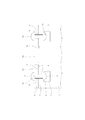
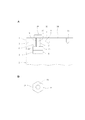
【解決手段】第1金属板1の一方の面3に第2金属板2の端縁4が突き合わされ、みぞ5が第2金属板2に形成される。みぞ5は幅の大きい部分6と幅の小さい部分7からなる。さらに、締め付け手段11,12,13が透孔9および幅の小さい部分7に通され、第1金属板1の他方の面10および肩部分8に係合し、締め付け手段11,12,13によって第1および第2金属板1,2が締め付けられ、固定される。
【選択図】図1
Description
2 第2金属板
3 一方の面
4 端縁
5 みぞ
6 幅の大きい部分
7 幅の小さい部分
8 肩部分
9 透孔
10 他方の面
11 リベット
12,13 ヘッド
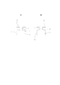
14 ダボ
15 ダボ孔
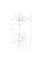
16 ワッシャ
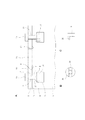
17 ボルト
18 ナット
19 ヘッド
Claims (8)
- 第1および第2金属板を互いに垂直に配置し、前記第1金属板の一方の面に前記第2金属板の端縁を突き合せたフレームであって、
前記第2金属板に形成され、前記端縁に向かってのび、幅の大きい部分と幅の小さい部分からなり、前記端縁と前記幅の大きい部分間に前記幅の小さい部分が位置し、前記幅の大きい部分と前記幅の小さい部分間に肩部分が形成されているみぞと、
前記みぞに対応する位置において、前記第1金属板に形成された透孔と、
前記透孔および前記幅の小さい部分に通され、前記第1金属板の他方の面および前記肩部分に係合し、前記第1金属板の他方の面と前記肩部分間において、前記第1および第2金属板を締め付け、固定する締め付け手段とを備えたことを特徴とするフレーム。 - 前記締め付け手段はリベットであり、前記リベットが前記透孔および前記幅の小さい部分に通され、そのヘッドが前記第1金属板の他方の面および前記肩部分に係合していることを特徴とする請求項1に記載のフレーム。
- 前記締め付け手段はリベットとワッシャからなり、前記ワッシャが前記幅の大きい部分に配置され、前記リベットが前記透孔、前記幅の小さい部分および前記ワッシャに通され、そのヘッドが前記第1金属板の他方の面および前記ワッシャに係合し、前記ワッシャが前記肩部分に係合していることを特徴とする請求項1に記載のフレーム。
- 前記締め付け手段はボルトとナットからなり、前記ナットが前記幅の大きい部分に配置され、前記ボルトが前記透孔および前記幅の小さい部分に通され、前記ナットにねじ合わされ、そのヘッドが前記第1金属板の他方の面に係合し、前記ナットが前記肩部分に係合していることを特徴とする請求項1に記載のフレーム。
- 前記締め付け手段はボルト、ワッシャおよびナットからなり、前記ワッシャおよびナットが前記幅の大きい部分に配置され、前記ボルトが前記透孔、前記幅の小さい部分および前記ワッシャに通され、前記ナットにねじ合わされ、そのヘッドが前記第1金属板の他方の面に係合し、前記ナットが前記ワッシャに係合し、前記ワッシャが前記肩部分に係合していることを特徴とする請求項1に記載のフレーム。
- 前記第2金属板の端縁にダボが形成され、前記ダボに対応する位置において、ダボ孔が前記第1金属板に形成され、前記ダボが前記ダボ孔にはめ込まれていることを特徴とする請求項1に記載のフレーム。
- 前記第2金属板は複数の前記みぞを有し、複数の前記ダボを有し、前記第1金属板は複数の前記透孔を有し、複数の前記ダボ孔を有し、互いに間隔を置いて前記各みぞが形成され、前記各みぞの位置において、それぞれ前記透孔が形成され、互いに間隔を置いて前記各ダボが形成され、前記各ダボの位置において、それぞれ前記ダボ孔が形成されていることを特徴とする請求項6に記載のフレーム。
- 前記みぞはレーザ加工されたものであることを特徴とする請求項1に記載のフレーム。
Priority Applications (1)
| Application Number | Priority Date | Filing Date | Title |
|---|---|---|---|
| JP2008224620A JP5322540B2 (ja) | 2008-09-02 | 2008-09-02 | フレーム |
Applications Claiming Priority (1)
| Application Number | Priority Date | Filing Date | Title |
|---|---|---|---|
| JP2008224620A JP5322540B2 (ja) | 2008-09-02 | 2008-09-02 | フレーム |
Publications (2)
| Publication Number | Publication Date |
|---|---|
| JP2010058313A true JP2010058313A (ja) | 2010-03-18 |
| JP5322540B2 JP5322540B2 (ja) | 2013-10-23 |
Family
ID=42185687
Family Applications (1)
| Application Number | Title | Priority Date | Filing Date |
|---|---|---|---|
| JP2008224620A Active JP5322540B2 (ja) | 2008-09-02 | 2008-09-02 | フレーム |
Country Status (1)
| Country | Link |
|---|---|
| JP (1) | JP5322540B2 (ja) |
Citations (6)
| Publication number | Priority date | Publication date | Assignee | Title |
|---|---|---|---|---|
| JPS4984855U (ja) * | 1972-11-10 | 1974-07-23 | ||
| JPS5072872U (ja) * | 1973-11-06 | 1975-06-26 | ||
| JPS5321271U (ja) * | 1976-08-02 | 1978-02-22 | ||
| JPH01145408A (ja) * | 1987-11-30 | 1989-06-07 | Canon Inc | 締結部材 |
| JPH11270517A (ja) * | 1998-03-24 | 1999-10-05 | Kawasaki Steel Corp | メタルラスの固定方法 |
| JP2008121723A (ja) * | 2006-11-09 | 2008-05-29 | Mk Seiko Co Ltd | 基材におけるナット保持構造 |
-
2008
- 2008-09-02 JP JP2008224620A patent/JP5322540B2/ja active Active
Patent Citations (6)
| Publication number | Priority date | Publication date | Assignee | Title |
|---|---|---|---|---|
| JPS4984855U (ja) * | 1972-11-10 | 1974-07-23 | ||
| JPS5072872U (ja) * | 1973-11-06 | 1975-06-26 | ||
| JPS5321271U (ja) * | 1976-08-02 | 1978-02-22 | ||
| JPH01145408A (ja) * | 1987-11-30 | 1989-06-07 | Canon Inc | 締結部材 |
| JPH11270517A (ja) * | 1998-03-24 | 1999-10-05 | Kawasaki Steel Corp | メタルラスの固定方法 |
| JP2008121723A (ja) * | 2006-11-09 | 2008-05-29 | Mk Seiko Co Ltd | 基材におけるナット保持構造 |
Also Published As
| Publication number | Publication date |
|---|---|
| JP5322540B2 (ja) | 2013-10-23 |
Similar Documents
| Publication | Publication Date | Title |
|---|---|---|
| US10047513B2 (en) | Beam frame assembly having joint device | |
| US10389092B2 (en) | Frame assembly body and casing | |
| JPH0755421B2 (ja) | 工作物を固定するクランプ装置、及び該クランプ装置で使用されるように構成されたクランプバー | |
| KR101458745B1 (ko) | 테이블 프레임 및 그 조립방법 | |
| JP2015214881A (ja) | 梁用接続装置 | |
| US20060214073A1 (en) | Fabricated heavy duty structural clamp | |
| US6629678B1 (en) | Seismic adapter | |
| JP5322540B2 (ja) | フレーム | |
| JP2012177281A (ja) | 屋根上搭載機器の取付け金具 | |
| JP4960166B2 (ja) | 引き寄せ金物 | |
| JP2021095920A (ja) | パイプ取り付け用クランプ | |
| JP7201171B2 (ja) | 押出成形セメント板床材の取付金具とそれを用いた床材取付構造 | |
| JP4074639B2 (ja) | H型鉄骨のウェブ接続用スプライス板の仮止め用治具 | |
| JP4570681B1 (ja) | 取付用金具 | |
| JP2011026024A (ja) | エレベータの三方枠 | |
| JP4060280B2 (ja) | 木質構造部材の接合構造 | |
| JP4899017B2 (ja) | 部材の結合構造 | |
| KR20180107615A (ko) | 프레임 체결체 | |
| JP2015113650A (ja) | フェンス用網状パネルの接続構造 | |
| KR20190003135A (ko) | 세 방향 또는 네 방향 파이프 체결용 클램프 | |
| JP3142771U (ja) | 覆工板固定金具 | |
| JP4326653B2 (ja) | 柱と横架材の接合装置 | |
| JP3107907U (ja) | 取付金具 | |
| JP2005282018A (ja) | 鉄筋又はアンカーボルト固定用のテンプレート | |
| JP2008057138A (ja) | 壁パネル取付装置 |
Legal Events
| Date | Code | Title | Description |
|---|---|---|---|
| A621 | Written request for application examination |
Free format text: JAPANESE INTERMEDIATE CODE: A621 Effective date: 20110815 |
|
| A977 | Report on retrieval |
Free format text: JAPANESE INTERMEDIATE CODE: A971007 Effective date: 20130110 |
|
| A131 | Notification of reasons for refusal |
Free format text: JAPANESE INTERMEDIATE CODE: A131 Effective date: 20130116 |
|
| A521 | Request for written amendment filed |
Free format text: JAPANESE INTERMEDIATE CODE: A523 Effective date: 20130222 |
|
| TRDD | Decision of grant or rejection written | ||
| A01 | Written decision to grant a patent or to grant a registration (utility model) |
Free format text: JAPANESE INTERMEDIATE CODE: A01 Effective date: 20130626 |
|
| A61 | First payment of annual fees (during grant procedure) |
Free format text: JAPANESE INTERMEDIATE CODE: A61 Effective date: 20130716 |
|
| R150 | Certificate of patent or registration of utility model |
Ref document number: 5322540 Country of ref document: JP Free format text: JAPANESE INTERMEDIATE CODE: R150 Free format text: JAPANESE INTERMEDIATE CODE: R150 |
|
| R250 | Receipt of annual fees |
Free format text: JAPANESE INTERMEDIATE CODE: R250 |
|
| R250 | Receipt of annual fees |
Free format text: JAPANESE INTERMEDIATE CODE: R250 |
|
| R250 | Receipt of annual fees |
Free format text: JAPANESE INTERMEDIATE CODE: R250 |
|
| R250 | Receipt of annual fees |
Free format text: JAPANESE INTERMEDIATE CODE: R250 |