JP2010053396A - 高炉荒れ出銑抑制方法 - Google Patents
高炉荒れ出銑抑制方法 Download PDFInfo
- Publication number
- JP2010053396A JP2010053396A JP2008219144A JP2008219144A JP2010053396A JP 2010053396 A JP2010053396 A JP 2010053396A JP 2008219144 A JP2008219144 A JP 2008219144A JP 2008219144 A JP2008219144 A JP 2008219144A JP 2010053396 A JP2010053396 A JP 2010053396A
- Authority
- JP
- Japan
- Prior art keywords
- press
- fitting
- blast furnace
- hole
- viscosity
- Prior art date
- Legal status (The legal status is an assumption and is not a legal conclusion. Google has not performed a legal analysis and makes no representation as to the accuracy of the status listed.)
- Granted
Links
Images

Classifications
-
- F—MECHANICAL ENGINEERING; LIGHTING; HEATING; WEAPONS; BLASTING
- F27—FURNACES; KILNS; OVENS; RETORTS
- F27B—FURNACES, KILNS, OVENS OR RETORTS IN GENERAL; OPEN SINTERING OR LIKE APPARATUS
- F27B1/00—Shaft or like vertical or substantially vertical furnaces
- F27B1/10—Details, accessories or equipment specially adapted for furnaces of these types
- F27B1/21—Arrangements of devices for discharging
-
- C—CHEMISTRY; METALLURGY
- C21—METALLURGY OF IRON
- C21B—MANUFACTURE OF IRON OR STEEL
- C21B7/00—Blast furnaces
- C21B7/04—Blast furnaces with special refractories
- C21B7/06—Linings for furnaces
-
- C—CHEMISTRY; METALLURGY
- C21—METALLURGY OF IRON
- C21B—MANUFACTURE OF IRON OR STEEL
- C21B7/00—Blast furnaces
- C21B7/14—Discharging devices, e.g. for slag
-
- F—MECHANICAL ENGINEERING; LIGHTING; HEATING; WEAPONS; BLASTING
- F27—FURNACES; KILNS; OVENS; RETORTS
- F27B—FURNACES, KILNS, OVENS OR RETORTS IN GENERAL; OPEN SINTERING OR LIKE APPARATUS
- F27B1/00—Shaft or like vertical or substantially vertical furnaces
- F27B1/10—Details, accessories or equipment specially adapted for furnaces of these types
-
- F—MECHANICAL ENGINEERING; LIGHTING; HEATING; WEAPONS; BLASTING
- F27—FURNACES; KILNS; OVENS; RETORTS
- F27D—DETAILS OR ACCESSORIES OF FURNACES, KILNS, OVENS OR RETORTS, IN SO FAR AS THEY ARE OF KINDS OCCURRING IN MORE THAN ONE KIND OF FURNACE
- F27D1/00—Casings; Linings; Walls; Roofs
- F27D1/16—Making or repairing linings ; Increasing the durability of linings; Breaking away linings
-
- F—MECHANICAL ENGINEERING; LIGHTING; HEATING; WEAPONS; BLASTING
- F27—FURNACES; KILNS; OVENS; RETORTS
- F27D—DETAILS OR ACCESSORIES OF FURNACES, KILNS, OVENS OR RETORTS, IN SO FAR AS THEY ARE OF KINDS OCCURRING IN MORE THAN ONE KIND OF FURNACE
- F27D3/00—Charging; Discharging; Manipulation of charge
- F27D3/15—Tapping equipment; Equipment for removing or retaining slag
Landscapes
- Engineering & Computer Science (AREA)
- Chemical & Material Sciences (AREA)
- Mechanical Engineering (AREA)
- General Engineering & Computer Science (AREA)
- Manufacturing & Machinery (AREA)
- Materials Engineering (AREA)
- Metallurgy (AREA)
- Organic Chemistry (AREA)
- Blast Furnaces (AREA)
- Furnace Housings, Linings, Walls, And Ceilings (AREA)
Abstract
【解決手段】出銑孔6横に設けた圧入孔9から高炉ライニング背面の隙間へ高粘性圧入材を圧入する高炉荒れ出銑抑制方法であって、粘性2000〜7000cPの高粘性圧入材を、出銑中に出銑孔近傍に生じるエゼクター効果を利用して圧入する。
【選択図】図3
Description
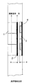
一方で、炉内ガスシール効果の高い高粘性圧入材を使用した場合は、圧入孔または圧入配管の閉塞が問題となり、圧入材の圧入圧力を高めて圧入すると図1に記すような内張りれんが1を押し出す等、高炉炉壁を損傷させる懸念があるため、設備保護上の観点から圧入圧力を高めて高粘性圧入材を圧入することが困難であった。
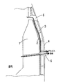
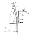
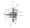
図3には、本発明の高炉荒れ出銑抑制方法の概略説明図を示している。図4には、本発明に用いる出銑孔横に設けた圧入孔の位置説明図を示している。図5には、本発明の一実施形態を示している。
図4に示すように、前記圧入孔9は、出銑孔の周囲0.5〜4mの位置に設けられている。圧入孔9の設置位置が出銑孔6の周囲0.5mより近い場合は、出銑孔6横に設置された圧入孔9に接続される配管10が、出銑孔から飛散する溶銑により損傷する懸念がある。また、圧入孔9の設置位置が出銑孔6の周囲4mより遠い場合は、出銑時のエゼクター効果による炉内圧力低下が十分に得られないため、高粘性圧入材を圧入することが困難となる。このため、圧入孔9は出銑孔6横の周囲0.5〜4mの位置に設置することが望ましい。
前記の高炉の羽口下に炉全周にわたって、内径40Aの圧入孔が42箇所設置されている。圧入機を溶銑の飛散が及ばない羽口デッキに設置し、1回の圧入作業で10箇所程度の羽口下に設けられた圧入孔から圧入した。圧入材はフラン系樹脂と黒鉛の混練物であって、1000cPの粘度を有するものを、1箇所の圧入孔に対して約100kg使用した。圧入にあたっては、操業中に前記の圧力確認と弁操作を実施し、圧入圧力1.5〜1.8MPaで圧入した。圧入による大樋、カバーの寿命を確認した結果、図6に示すように大樋は出銑量7.0万トン、図7に示すようにカバーは出銑量3.0万トンであり、図10に示すように圧入による炉内ガスシール効果は、2〜3日間継続した。
2 スタンプ層
3 ステーブ
4 鉄皮
5 羽口
6 出銑孔
7 圧入機
8 羽口デッキ
9 圧入孔
10 延長配管
11 圧力計A
12 圧力計B
13a〜13c ボール弁
Claims (5)
- 出銑孔横に設けた圧入孔から、出銑孔周辺部の高炉ライニング背面隙間へ、高粘性圧入材を圧入する高炉荒れ出銑抑制方法であって、
粘性2000〜7000cPの高粘性圧入材を、出銑中に出銑孔近傍に生じるエゼクター効果を利用して圧入することを特徴とする高炉荒れ出銑抑制方法。 - 圧入孔は、出銑孔の周囲0.5〜4mの位置に設けたことを特徴とする請求項1記載の高炉荒れ出銑抑制方法。
- 炉内圧力検出手段によりエゼクター効果の発生を検出し、エゼクター効果発生確認後に圧入を開始することを特徴とする請求項1または2記載の高炉荒れ出銑抑制方法。
- 高粘性圧入材圧入後に、樹脂のみの圧入を行うことを特徴とする請求項1〜3の何れかに記載の高炉荒れ出銑抑制方法。
- 羽口下に設けた圧入孔から粘性20〜2000cPの低粘性圧入材の圧入を組み合わせて行うことを特徴とする請求項1〜4の何れかに記載の高炉荒れ出銑抑制方法。
Priority Applications (5)
| Application Number | Priority Date | Filing Date | Title |
|---|---|---|---|
| JP2008219144A JP4516995B2 (ja) | 2008-08-28 | 2008-08-28 | 高炉荒れ出銑抑制方法 |
| KR1020117002224A KR101235550B1 (ko) | 2008-08-28 | 2009-08-21 | 고로 거친 출선 억제 방법 |
| PCT/JP2009/065011 WO2010024360A1 (ja) | 2008-08-28 | 2009-08-21 | 高炉荒れ出銑抑制方法 |
| CN2009801219564A CN102057057B (zh) | 2008-08-28 | 2009-08-21 | 高炉不稳定出铁抑制方法 |
| BRPI0917177-0A BRPI0917177B1 (pt) | 2008-08-28 | 2009-08-21 | High-oven irregular leak suppression method |
Applications Claiming Priority (1)
| Application Number | Priority Date | Filing Date | Title |
|---|---|---|---|
| JP2008219144A JP4516995B2 (ja) | 2008-08-28 | 2008-08-28 | 高炉荒れ出銑抑制方法 |
Publications (2)
| Publication Number | Publication Date |
|---|---|
| JP2010053396A true JP2010053396A (ja) | 2010-03-11 |
| JP4516995B2 JP4516995B2 (ja) | 2010-08-04 |
Family
ID=41721525
Family Applications (1)
| Application Number | Title | Priority Date | Filing Date |
|---|---|---|---|
| JP2008219144A Active JP4516995B2 (ja) | 2008-08-28 | 2008-08-28 | 高炉荒れ出銑抑制方法 |
Country Status (5)
| Country | Link |
|---|---|
| JP (1) | JP4516995B2 (ja) |
| KR (1) | KR101235550B1 (ja) |
| CN (1) | CN102057057B (ja) |
| BR (1) | BRPI0917177B1 (ja) |
| WO (1) | WO2010024360A1 (ja) |
Cited By (1)
| Publication number | Priority date | Publication date | Assignee | Title |
|---|---|---|---|---|
| CN102719583A (zh) * | 2012-07-03 | 2012-10-10 | 鞍钢集团工程技术有限公司 | 一种延长高炉炉缸、炉底寿命的方法 |
Citations (4)
| Publication number | Priority date | Publication date | Assignee | Title |
|---|---|---|---|---|
| JPS63297487A (ja) * | 1987-05-29 | 1988-12-05 | Harima Ceramic Co Ltd | 間隙部充填用圧入材 |
| JPH0535841U (ja) * | 1991-10-16 | 1993-05-14 | 住友金属工業株式会社 | 高炉出銑口の耐火物補修装置 |
| JPH06100913A (ja) * | 1992-09-18 | 1994-04-12 | Nippon Steel Corp | 精錬容器の圧入補修方法 |
| JPH11293310A (ja) * | 1998-04-13 | 1999-10-26 | Nippon Steel Corp | 高炉炉底側壁補修方法及び装置 |
Family Cites Families (4)
| Publication number | Priority date | Publication date | Assignee | Title |
|---|---|---|---|---|
| JPS527308A (en) * | 1975-07-08 | 1977-01-20 | Sumitomo Metal Ind Ltd | Method and apparatus for gas sealing of tap hole in blast furnaces |
| SE434650B (sv) * | 1982-06-09 | 1984-08-06 | Skf Steel Eng Ab | Sett vid utnyttjande av plasmagenerator for hojning av blestertemperaturen i en schaktugn |
| JPH0535841A (ja) * | 1991-07-31 | 1993-02-12 | Toshiba Corp | 画像記憶装置 |
| JPH11229011A (ja) * | 1998-02-16 | 1999-08-24 | Kawasaki Steel Corp | 高炉炉体の補修方法 |
-
2008
- 2008-08-28 JP JP2008219144A patent/JP4516995B2/ja active Active
-
2009
- 2009-08-21 CN CN2009801219564A patent/CN102057057B/zh not_active Expired - Fee Related
- 2009-08-21 KR KR1020117002224A patent/KR101235550B1/ko not_active Expired - Fee Related
- 2009-08-21 BR BRPI0917177-0A patent/BRPI0917177B1/pt not_active IP Right Cessation
- 2009-08-21 WO PCT/JP2009/065011 patent/WO2010024360A1/ja not_active Ceased
Patent Citations (4)
| Publication number | Priority date | Publication date | Assignee | Title |
|---|---|---|---|---|
| JPS63297487A (ja) * | 1987-05-29 | 1988-12-05 | Harima Ceramic Co Ltd | 間隙部充填用圧入材 |
| JPH0535841U (ja) * | 1991-10-16 | 1993-05-14 | 住友金属工業株式会社 | 高炉出銑口の耐火物補修装置 |
| JPH06100913A (ja) * | 1992-09-18 | 1994-04-12 | Nippon Steel Corp | 精錬容器の圧入補修方法 |
| JPH11293310A (ja) * | 1998-04-13 | 1999-10-26 | Nippon Steel Corp | 高炉炉底側壁補修方法及び装置 |
Cited By (1)
| Publication number | Priority date | Publication date | Assignee | Title |
|---|---|---|---|---|
| CN102719583A (zh) * | 2012-07-03 | 2012-10-10 | 鞍钢集团工程技术有限公司 | 一种延长高炉炉缸、炉底寿命的方法 |
Also Published As
| Publication number | Publication date |
|---|---|
| CN102057057B (zh) | 2013-04-10 |
| KR20110023909A (ko) | 2011-03-08 |
| JP4516995B2 (ja) | 2010-08-04 |
| BRPI0917177A2 (pt) | 2015-11-10 |
| KR101235550B1 (ko) | 2013-02-21 |
| CN102057057A (zh) | 2011-05-11 |
| WO2010024360A1 (ja) | 2010-03-04 |
| BRPI0917177B1 (pt) | 2017-09-12 |
Similar Documents
| Publication | Publication Date | Title |
|---|---|---|
| CA2937172C (en) | Pneumatic ore charging | |
| CN113574184A (zh) | 炉底升温方法以及该方法中使用的燃烧器喷枪 | |
| JP4516995B2 (ja) | 高炉荒れ出銑抑制方法 | |
| JP5978594B2 (ja) | 高炉送風羽口保持金物のガスシール構造及びガスシール方法 | |
| CA2971980C (en) | Method of sealing and repairing a refractory tap hole | |
| CN113088592A (zh) | 一种高炉冷热面在线压浆工艺 | |
| KR101562451B1 (ko) | 스테이브 냉각 파이프용 보수재 및 보수방법 | |
| CN216811715U (zh) | 减少钢衬底部回填混凝土脱空的装置 | |
| JP2017166009A (ja) | 高炉溶銑大樋での溶銑滓処理方法及び高炉溶銑大樋スキンマーダンパー | |
| CN112539040A (zh) | 一种新的注浆封孔装置和工艺 | |
| CN104110541A (zh) | 高压设备的法兰面和密封垫片泄漏处封堵方法及其装置 | |
| EP1233077B1 (en) | Apparatus for repairing blast furnace taphole facings | |
| KR102112537B1 (ko) | 고로 노체 냉각 장치 | |
| CN104328236A (zh) | 一种高炉装料情况下更换冷却设备的方法 | |
| KR101050801B1 (ko) | 용융로용 더스트 버너의 노즐 | |
| CN116287517A (zh) | 欧冶炉全氧冶炼铁水的高温熔融渣铁排口及出渣方法 | |
| JP2617859B2 (ja) | 精錬容器の圧入補修方法 | |
| KR100822971B1 (ko) | 보조재를 이용한 용광로의 출선구 폐쇄방법 | |
| CN207775273U (zh) | 一种高炉主沟和渣铁沟的搭接结构 | |
| CN120310977A (zh) | 一种用于铁口泥包的在线修复方法 | |
| KR101036913B1 (ko) | 고로의 머드건과 노즐팁 사이의 틈새 메움용 장치 및 방법 | |
| JP2023027519A (ja) | 高炉炉内充填物の堆積形状の推定方法および高炉炉内コークスの置換方法 | |
| JP2016098428A (ja) | 高炉ステーブクーラー周辺への不定形耐火物の施工方法 | |
| JP2007314818A (ja) | 高炉のステーブクーラー周辺への不定形耐火物の充填方法 | |
| FR3073920B1 (fr) | Procede de protection et procede de reconditionnement d'une conduite de transfert de fluide ; dispositif de transfert de fluide et installation d'alimentation en ergol pour moteur-fusee |
Legal Events
| Date | Code | Title | Description |
|---|---|---|---|
| A521 | Written amendment |
Free format text: JAPANESE INTERMEDIATE CODE: A523 Effective date: 20100118 |
|
| TRDD | Decision of grant or rejection written | ||
| A01 | Written decision to grant a patent or to grant a registration (utility model) |
Free format text: JAPANESE INTERMEDIATE CODE: A01 Effective date: 20100423 |
|
| A01 | Written decision to grant a patent or to grant a registration (utility model) |
Free format text: JAPANESE INTERMEDIATE CODE: A01 |
|
| A61 | First payment of annual fees (during grant procedure) |
Free format text: JAPANESE INTERMEDIATE CODE: A61 Effective date: 20100517 |
|
| R151 | Written notification of patent or utility model registration |
Ref document number: 4516995 Country of ref document: JP Free format text: JAPANESE INTERMEDIATE CODE: R151 |
|
| FPAY | Renewal fee payment (event date is renewal date of database) |
Free format text: PAYMENT UNTIL: 20130521 Year of fee payment: 3 |
|
| S533 | Written request for registration of change of name |
Free format text: JAPANESE INTERMEDIATE CODE: R313533 |
|
| FPAY | Renewal fee payment (event date is renewal date of database) |
Free format text: PAYMENT UNTIL: 20130521 Year of fee payment: 3 |
|
| R350 | Written notification of registration of transfer |
Free format text: JAPANESE INTERMEDIATE CODE: R350 |
|
| FPAY | Renewal fee payment (event date is renewal date of database) |
Free format text: PAYMENT UNTIL: 20140521 Year of fee payment: 4 |
|
| S533 | Written request for registration of change of name |
Free format text: JAPANESE INTERMEDIATE CODE: R313533 |
|
| R350 | Written notification of registration of transfer |
Free format text: JAPANESE INTERMEDIATE CODE: R350 |