JP2010048317A - 部材連結装置 - Google Patents
部材連結装置 Download PDFInfo
- Publication number
- JP2010048317A JP2010048317A JP2008212379A JP2008212379A JP2010048317A JP 2010048317 A JP2010048317 A JP 2010048317A JP 2008212379 A JP2008212379 A JP 2008212379A JP 2008212379 A JP2008212379 A JP 2008212379A JP 2010048317 A JP2010048317 A JP 2010048317A
- Authority
- JP
- Japan
- Prior art keywords
- clamping
- shaped
- sandwiching
- members
- pair
- Prior art date
- Legal status (The legal status is an assumption and is not a legal conclusion. Google has not performed a legal analysis and makes no representation as to the accuracy of the status listed.)
- Granted
Links
- 230000008878 coupling Effects 0.000 claims description 5
- 238000010168 coupling process Methods 0.000 claims description 5
- 238000005859 coupling reaction Methods 0.000 claims description 5
- 238000003780 insertion Methods 0.000 description 8
- 230000037431 insertion Effects 0.000 description 8
- 239000000463 material Substances 0.000 description 4
- 238000000034 method Methods 0.000 description 3
- 238000010079 rubber tapping Methods 0.000 description 2
- 230000002159 abnormal effect Effects 0.000 description 1
- 230000000694 effects Effects 0.000 description 1
- 239000002184 metal Substances 0.000 description 1
- 230000004048 modification Effects 0.000 description 1
- 238000012986 modification Methods 0.000 description 1
Images


Landscapes
- Mutual Connection Of Rods And Tubes (AREA)
Abstract
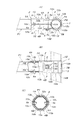
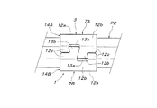
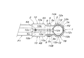
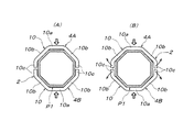
【解決手段】正8角形又は正16角形の角柱状外側面を有する第一部材P1を挟持する第一挟持手段2は、一対の挟持部材4A,4Bと、締結用ボルトナット5と、固定具6A,6Bとを備え、各挟持部材4A,4Bの挟持部10には、記締結用ボルトナット5の軸方向に対して直角向きの中央挟持板部10aと、ハ形挟持板部10bと、平行側板部10cが設けられ、固定具6A,6Bは、各挟持部材4A,4Bの挟持部10間で第一部材P1を、その角柱状外側面と各挟持板部10a,10bとがほぼ平行に対面する状態で挟持させたとき、締結用ボルトナット5の軸方向と平行な第一部材P1の外側面に、両挟持部10の互いに隣接する平行側板部10c間を通る位置で取り付けられた構成。
【選択図】図1
Description
特願2007−278391
P6 丸パイプ材
1 部材連結装置
2 第一挟持手段
3 第二挟持手段
4A,4B 第一挟持手段の挟持部材
5 締結用ボルトナット
6A,6B 固定具
7A,7B 第二挟持手段の挟持部材
8 ボルト挿通孔
9 基部
10,12 挟持部
10a,12a 中央挟持板部
10b,12b ハ形挟持板部
10c 平行側板部
10e 段部
10f,10g 中間傾斜板部
11 切り欠き凹部
12c 外側板部
13a 蟻溝形凹部
13b 逆台形突起部
14A,14B 挟持体
15 凹溝部
P1,P3 棒状第一部材
P2 棒状第二部材
Claims (2)
- 正8角形又は正16角形の角柱状外側面を有する第一部材を挟持する第一挟持手段と、前記第一部材と連結する第二部材を挟持する第二挟持手段とが連設され、第一挟持手段は、一対の挟持部材と、この一対の挟持部材を互いに締結する締結用ボルトナットと、固定具とを備え、前記一対の挟持部材には、前記締結用ボルトナットの位置から離れた位置で第一部材を挟持する挟持部が設けられ、各挟持部には、前記締結用ボルトナットの軸方向に対して直角向きの中央挟持板部と、この中央挟持板部の両側辺に連なるハ形挟持板部と、両ハ形挟持板部に連なり且つ前記中央挟持板部に対し直角向きの平行側板部が設けられ、前記固定具は、一対の挟持部材の挟持部間で第一部材を、その角柱状外側面と前記各挟持板部とがほぼ平行に対面する状態で挟持させたとき、前記締結用ボルトナットの軸方向と平行な第一部材の両外側面に、両挟持部の互いに隣接する前記平行側板部間を通る位置で取り付けられ、この固定具の頭部によって両挟持部の前記平行側板部が外側へ広がるのを阻止している、部材連結装置。
- 前記一対の挟持部材の挟持部における前記平行側板部の側辺には、前記固定具の軸部が嵌合する切り込み凹部がそれぞれ設けられている、請求項1に記載の部材連結装置。
Priority Applications (1)
| Application Number | Priority Date | Filing Date | Title |
|---|---|---|---|
| JP2008212379A JP4894022B2 (ja) | 2008-08-21 | 2008-08-21 | 部材連結装置 |
Applications Claiming Priority (1)
| Application Number | Priority Date | Filing Date | Title |
|---|---|---|---|
| JP2008212379A JP4894022B2 (ja) | 2008-08-21 | 2008-08-21 | 部材連結装置 |
Publications (2)
| Publication Number | Publication Date |
|---|---|
| JP2010048317A true JP2010048317A (ja) | 2010-03-04 |
| JP4894022B2 JP4894022B2 (ja) | 2012-03-07 |
Family
ID=42065570
Family Applications (1)
| Application Number | Title | Priority Date | Filing Date |
|---|---|---|---|
| JP2008212379A Expired - Fee Related JP4894022B2 (ja) | 2008-08-21 | 2008-08-21 | 部材連結装置 |
Country Status (1)
| Country | Link |
|---|---|
| JP (1) | JP4894022B2 (ja) |
Citations (4)
| Publication number | Priority date | Publication date | Assignee | Title |
|---|---|---|---|---|
| JPS61167756A (ja) * | 1985-01-19 | 1986-07-29 | Toyota Motor Corp | 変速機の制御装置 |
| JPH08159119A (ja) * | 1994-12-07 | 1996-06-18 | N I Shi Auto Tec Kk | 連結材 |
| JP2000046019A (ja) * | 1998-07-24 | 2000-02-15 | Yoshino Kosakusho:Kk | 割り型継手 |
| JP2004169775A (ja) * | 2002-11-19 | 2004-06-17 | Yazaki Ind Chem Co Ltd | 継手とパイプの結合構造 |
-
2008
- 2008-08-21 JP JP2008212379A patent/JP4894022B2/ja not_active Expired - Fee Related
Patent Citations (4)
| Publication number | Priority date | Publication date | Assignee | Title |
|---|---|---|---|---|
| JPS61167756A (ja) * | 1985-01-19 | 1986-07-29 | Toyota Motor Corp | 変速機の制御装置 |
| JPH08159119A (ja) * | 1994-12-07 | 1996-06-18 | N I Shi Auto Tec Kk | 連結材 |
| JP2000046019A (ja) * | 1998-07-24 | 2000-02-15 | Yoshino Kosakusho:Kk | 割り型継手 |
| JP2004169775A (ja) * | 2002-11-19 | 2004-06-17 | Yazaki Ind Chem Co Ltd | 継手とパイプの結合構造 |
Also Published As
| Publication number | Publication date |
|---|---|
| JP4894022B2 (ja) | 2012-03-07 |
Similar Documents
| Publication | Publication Date | Title |
|---|---|---|
| US7464905B2 (en) | Tubular material fixation device | |
| JP2009299885A (ja) | 弛み防止ボルト | |
| US20130243543A1 (en) | Connector | |
| JP2014051818A (ja) | ブレース取付具 | |
| JP5411593B2 (ja) | ワイヤー張設具 | |
| JP4894022B2 (ja) | 部材連結装置 | |
| JP6313737B2 (ja) | ブレース連結金具 | |
| KR20100011234U (ko) | 칸막이용 프레임의 연결장치 | |
| JP6778953B2 (ja) | プロファイル用コネクタ | |
| JP2005090681A (ja) | クリップ | |
| US20100294087A1 (en) | Tool sleeve clamping structure | |
| BR0305919A (pt) | Uma porca, um prendedor provido de uma porca e um dispositivo para fixação para o mesmo | |
| JP5248817B2 (ja) | 鉄筋とセパレータの接合金具 | |
| JP3138891U (ja) | スチールワイヤロープ用挟持具 | |
| JP4687040B2 (ja) | コンクリート部材のための接続装置 | |
| JP4954845B2 (ja) | 手工具用ホルダー | |
| KR200462117Y1 (ko) | 원형관 체결용 너트 고정구 | |
| JP3156294U (ja) | シートクリップ装置 | |
| JP2006183674A (ja) | 長手方向締結具、長手方向締結組立体およびその締結方法 | |
| JP7472161B2 (ja) | 索体引留金具、くさび着脱治具、及び、引抜治具 | |
| JPH10219848A (ja) | エクスパンションボルト | |
| JP2909404B2 (ja) | 配管類用締付け固定具 | |
| KR200401730Y1 (ko) | 너트와 너트 홀더의 구조 | |
| US20080247840A1 (en) | Fastener and Fastener Tightening/Loosening Device | |
| JP7173263B1 (ja) | ナットの取り外し方法及びナットの取り付け方法 |
Legal Events
| Date | Code | Title | Description |
|---|---|---|---|
| A621 | Written request for application examination |
Free format text: JAPANESE INTERMEDIATE CODE: A621 Effective date: 20101222 |
|
| A977 | Report on retrieval |
Free format text: JAPANESE INTERMEDIATE CODE: A971007 Effective date: 20111031 |
|
| TRDD | Decision of grant or rejection written | ||
| A01 | Written decision to grant a patent or to grant a registration (utility model) |
Free format text: JAPANESE INTERMEDIATE CODE: A01 Effective date: 20111125 |
|
| A01 | Written decision to grant a patent or to grant a registration (utility model) |
Free format text: JAPANESE INTERMEDIATE CODE: A01 |
|
| A61 | First payment of annual fees (during grant procedure) |
Free format text: JAPANESE INTERMEDIATE CODE: A61 Effective date: 20111208 |
|
| R150 | Certificate of patent or registration of utility model |
Ref document number: 4894022 Country of ref document: JP Free format text: JAPANESE INTERMEDIATE CODE: R150 Free format text: JAPANESE INTERMEDIATE CODE: R150 |
|
| FPAY | Renewal fee payment (event date is renewal date of database) |
Free format text: PAYMENT UNTIL: 20150106 Year of fee payment: 3 |
|
| R250 | Receipt of annual fees |
Free format text: JAPANESE INTERMEDIATE CODE: R250 |
|
| R250 | Receipt of annual fees |
Free format text: JAPANESE INTERMEDIATE CODE: R250 |
|
| R250 | Receipt of annual fees |
Free format text: JAPANESE INTERMEDIATE CODE: R250 |
|
| R250 | Receipt of annual fees |
Free format text: JAPANESE INTERMEDIATE CODE: R250 |
|
| R250 | Receipt of annual fees |
Free format text: JAPANESE INTERMEDIATE CODE: R250 |
|
| LAPS | Cancellation because of no payment of annual fees |