JP2010047399A - スクリュー駆動搬送装置 - Google Patents
スクリュー駆動搬送装置 Download PDFInfo
- Publication number
- JP2010047399A JP2010047399A JP2008215305A JP2008215305A JP2010047399A JP 2010047399 A JP2010047399 A JP 2010047399A JP 2008215305 A JP2008215305 A JP 2008215305A JP 2008215305 A JP2008215305 A JP 2008215305A JP 2010047399 A JP2010047399 A JP 2010047399A
- Authority
- JP
- Japan
- Prior art keywords
- screw
- shaft
- rib plates
- screw shaft
- cylindrical member
- Prior art date
- Legal status (The legal status is an assumption and is not a legal conclusion. Google has not performed a legal analysis and makes no representation as to the accuracy of the status listed.)
- Granted
Links
- 230000007246 mechanism Effects 0.000 claims description 23
- 238000004519 manufacturing process Methods 0.000 abstract description 10
- 230000032258 transport Effects 0.000 description 36
- 230000000694 effects Effects 0.000 description 7
- 230000005540 biological transmission Effects 0.000 description 6
- 238000011144 upstream manufacturing Methods 0.000 description 6
- 238000003466 welding Methods 0.000 description 3
- 239000000463 material Substances 0.000 description 2
- 239000013585 weight reducing agent Substances 0.000 description 2
- 239000000428 dust Substances 0.000 description 1
- 230000020169 heat generation Effects 0.000 description 1
- 238000009434 installation Methods 0.000 description 1
- 238000000034 method Methods 0.000 description 1
- 230000008569 process Effects 0.000 description 1
- 239000007787 solid Substances 0.000 description 1
Images


Landscapes
- Screw Conveyors (AREA)
Abstract
【解決手段】スクリュー軸110の回転により搬送体120が係合して搬送されるスクリュー駆動搬送装置100において、スクリュー軸110が、円柱状の軸本体112に連続した螺旋状のスリットを持つ円筒部材114を複数のリブプレート117により同心状に保持してなること。
【選択図】図8
Description
さらに、スクリュー軸と螺旋板とが螺旋板の全長にわたって接触するため、螺旋板を精度良く制作し、精度良く両者を固定することは困難であり、かつ、固定作業の手間もかかるという問題があった。
また、本発明のスクリュー駆動搬送装置のスクリュー軸の軸本体と円筒部材と複数のリブプレートは、それぞれ同一材料であっても良く、別の材料としても良い。
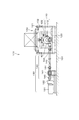
図1は、本発明の第1実施例であるスクリュー駆動搬送装置の斜視図であり、図2は、本発明の第1実施例であるスクリュー駆動搬送装置の側面図であり、図3は、本発明の第1実施例であるスクリュー駆動搬送装置の搬送体の平面図であり、図4は、本発明の第1実施例であるスクリュー駆動搬送装置の搬送体の正面図であり、図5は、本発明の第1実施例であるスクリュー駆動搬送装置の搬送体の側面図であり、図6は、本発明の第1実施例であるスクリュー駆動搬送装置の平面図であり、図7は、本発明の第1実施例であるスクリュー駆動搬送装置の配置図であり、図8は、本発明の第1実施例であるスクリュー駆動搬送装置のスクリュー軸の側面図であり、図9は、図8の一部拡大断面図であり、図10は、図9の正面図であり、図11は、図9のA−A断面図であり、図12は、図9のB−B断面図であり、図13は、本発明の第2実施例であるスクリュー駆動搬送装置のスクリュー軸の側面図であり、図14は、図13の正面図である。
なお、この場合、両側の駆動機構130のうち一方はモータ131を省略して回転伝達手段140のみとしてもよい。
端面リブプレート116および複数の中間リブプレート117と円筒部材114および軸本体112は、それぞれ溶接により固着されている。
また、軸本体112は軽量化のため中空パイプ部材で構成されている。
また、搬送体120の係合ローラ123が係合開始時に円筒部材114を変形させたり損傷する虞がない場合は、端面リブプレート116は省略しても良い。
複数の軸方向リブプレート118および複数の斜めリブプレート119と円筒部材114および軸本体112は、それぞれ溶接により固着されている。
また、軸本体112は軽量化のため中空パイプ部材で構成されている。
また、軸方向リブプレート118および斜めリブプレート119の数、位置、配置等は実施例に限定されるものではない。
さらに、前述した端面リブプレート116を設けても良い。
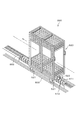
図7に示すように、上流からスクリュー軸110A、110B、110C、110D、110E、110F、110G、110H、110Jが直列に配置されており、スクリュー軸110Aは下流側に駆動機構130Aを、スクリュー軸110B、110C、110G、110Hは上流下流両側に駆動機構130B1、130B2、130C1、130C2、130G1、130G2、130H1、130H2を、スクリュー軸110Jは上流側に駆動機構130Jをそれぞれ備えており、スクリュー軸110D、110E、110Fは直接回転結合されて一体に回転するとともにスクリュー軸110Dの上流側に駆動機構130D、スクリュー軸110Fの下流側に駆動機構130Fが備えられている。
101、501 ・・・基礎部
102、502 ・・・ガイドレール
503 ・・・カバー体
110、510、710 ・・・スクリュー軸
511 ・・・螺旋板
112 ・・・軸本体
713 ・・・螺旋溝
114 ・・・円筒部材
115 ・・・スリット
116 ・・・端部リブプレート
117 ・・・中間リブプレート
118 ・・・軸方向リブプレート
119 ・・・斜めリブプレート
120、520、720 ・・・搬送体
121、521 ・・・車輪
122、522 ・・・ガイド体
123、523 ・・・係合ローラ
124 ・・・搬送体フレーム
130 ・・・駆動機構
131 ・・・モータ
132 ・・・出力軸
140 ・・・回転伝達手段
141 ・・・ギヤボックス
142 ・・・ドライブシャフト
143 ・・・最終ギヤ
144 ・・・自在継手
145 ・・・自在継手
146 ・・・継手
147 ・・・クラッチ軸
148 ・・・シングルポジション型クラッチ
Claims (6)
- 円周面に螺旋係合部を有するスクリュー軸と、該スクリュー軸を回転駆動する駆動機構とを有し、前記スクリュー軸の回転により搬送体が前記螺旋係合部に係合して搬送されるスクリュー駆動搬送装置において、
前記スクリュー軸が、円柱状の軸本体と、連続した螺旋状のスリットを持つ円筒部材と、該円筒部材を前記軸本体に同心状に保持する複数のリブプレートとを有していることを特徴とするスクリュー駆動搬送装置。 - 前記複数のリブプレートが、前記軸本体の軸方向と直角に交わる複数の平面に沿って形成されていることを特徴とする請求項1に記載のスクリュー駆動搬送装置。
- 前記複数のリブプレートが、前記螺旋係合部の軸方向両端面に設けられた端面リブプレートと中間部に適宜の間隔で設けられた中間リブプレートとからなり、
前記端面リブプレートが、前記円筒部材のスリット以外の全ての部分と前記軸本体とを接続する扇形状を有し、
前記中間リブプレートが、半円分の扇形状を有していることを特徴とする請求項2に記載のスクリュー駆動搬送装置。 - 前記複数のリブプレートが、前記軸本体の直径とほぼ等しい幅を有していることを特徴とする請求項1に記載のスクリュー駆動搬送装置。
- 前記複数のリブプレートが、前記スクリュー軸の軸方向に延びる軸方向リブプレートを含んでいることを特徴とする請求項4に記載のスクリュー駆動搬送装置。
- 前記複数のリブプレートが、前記円筒部材の螺旋状のスリット方向に延びる斜めリブプレートを含んでいることを特徴とする請求項4または請求項5に記載のスクリュー駆動搬送装置。
Priority Applications (1)
| Application Number | Priority Date | Filing Date | Title |
|---|---|---|---|
| JP2008215305A JP4553959B2 (ja) | 2008-08-25 | 2008-08-25 | スクリュー駆動搬送装置 |
Applications Claiming Priority (1)
| Application Number | Priority Date | Filing Date | Title |
|---|---|---|---|
| JP2008215305A JP4553959B2 (ja) | 2008-08-25 | 2008-08-25 | スクリュー駆動搬送装置 |
Related Child Applications (1)
| Application Number | Title | Priority Date | Filing Date |
|---|---|---|---|
| JP2010137484A Division JP2010228918A (ja) | 2010-06-16 | 2010-06-16 | スクリュー駆動搬送装置 |
Publications (2)
| Publication Number | Publication Date |
|---|---|
| JP2010047399A true JP2010047399A (ja) | 2010-03-04 |
| JP4553959B2 JP4553959B2 (ja) | 2010-09-29 |
Family
ID=42064837
Family Applications (1)
| Application Number | Title | Priority Date | Filing Date |
|---|---|---|---|
| JP2008215305A Expired - Fee Related JP4553959B2 (ja) | 2008-08-25 | 2008-08-25 | スクリュー駆動搬送装置 |
Country Status (1)
| Country | Link |
|---|---|
| JP (1) | JP4553959B2 (ja) |
Cited By (3)
| Publication number | Priority date | Publication date | Assignee | Title |
|---|---|---|---|---|
| JP2011037376A (ja) * | 2009-08-11 | 2011-02-24 | Tsubakimoto Chain Co | スクリュー駆動搬送装置 |
| CN102530497A (zh) * | 2010-10-29 | 2012-07-04 | 大福股份有限公司 | 台车推进用螺杆 |
| WO2013018578A1 (ja) * | 2011-08-01 | 2013-02-07 | 株式会社ダイフク | スクリュー駆動エリアへの搬送台車送込み装置 |
Citations (4)
| Publication number | Priority date | Publication date | Assignee | Title |
|---|---|---|---|---|
| US2284286A (en) * | 1939-08-08 | 1942-05-26 | Bliss E W Co | Container handling apparatus |
| JPS6031427A (ja) * | 1983-07-29 | 1985-02-18 | Yoshio Daiki | 直進間欠移送装置 |
| JPS6376711U (ja) * | 1986-11-06 | 1988-05-21 | ||
| JPH0958463A (ja) * | 1995-08-22 | 1997-03-04 | Daifuku Co Ltd | 台車使用の搬送設備 |
-
2008
- 2008-08-25 JP JP2008215305A patent/JP4553959B2/ja not_active Expired - Fee Related
Patent Citations (4)
| Publication number | Priority date | Publication date | Assignee | Title |
|---|---|---|---|---|
| US2284286A (en) * | 1939-08-08 | 1942-05-26 | Bliss E W Co | Container handling apparatus |
| JPS6031427A (ja) * | 1983-07-29 | 1985-02-18 | Yoshio Daiki | 直進間欠移送装置 |
| JPS6376711U (ja) * | 1986-11-06 | 1988-05-21 | ||
| JPH0958463A (ja) * | 1995-08-22 | 1997-03-04 | Daifuku Co Ltd | 台車使用の搬送設備 |
Cited By (6)
| Publication number | Priority date | Publication date | Assignee | Title |
|---|---|---|---|---|
| JP2011037376A (ja) * | 2009-08-11 | 2011-02-24 | Tsubakimoto Chain Co | スクリュー駆動搬送装置 |
| CN102530497A (zh) * | 2010-10-29 | 2012-07-04 | 大福股份有限公司 | 台车推进用螺杆 |
| WO2013018578A1 (ja) * | 2011-08-01 | 2013-02-07 | 株式会社ダイフク | スクリュー駆動エリアへの搬送台車送込み装置 |
| JP2013032189A (ja) * | 2011-08-01 | 2013-02-14 | Daifuku Co Ltd | スクリュー駆動エリアへの搬送台車送込み装置 |
| CN103717515A (zh) * | 2011-08-01 | 2014-04-09 | 株式会社大福 | 朝螺旋驱动区域送入台车的搬送台车送入装置 |
| US8720669B2 (en) | 2011-08-01 | 2014-05-13 | Daifuku Co., Ltd. | Device for delivering conveying truck into screw driving area |
Also Published As
| Publication number | Publication date |
|---|---|
| JP4553959B2 (ja) | 2010-09-29 |
Similar Documents
| Publication | Publication Date | Title |
|---|---|---|
| JP2008239348A (ja) | 媒体送り軸駆動システムにおける位置合わせ誤差低減方法及びシステム | |
| TW371703B (en) | Magnetic conveying apparatus, dynamic transmission of the magnetic conveying apparatus and the rotary driving mechanism | |
| CN104828518B (zh) | 基板输送装置 | |
| JP4553959B2 (ja) | スクリュー駆動搬送装置 | |
| CN105752671B (zh) | 传送定位机构 | |
| CN111107986A (zh) | 用于转换机的工具头定位机构、以及用于在转换机中定位多个工具头的方法 | |
| JP4588775B2 (ja) | スクリュー駆動式台車搬送装置 | |
| JP2010228918A (ja) | スクリュー駆動搬送装置 | |
| JP5414220B2 (ja) | スクリュー駆動搬送装置 | |
| JP2009067561A5 (ja) | ||
| JP5535682B2 (ja) | スクリュー駆動搬送装置 | |
| JP2011241021A5 (ja) | ||
| JP2009263019A (ja) | スクリュー駆動搬送装置 | |
| JP4566250B2 (ja) | スクリュー駆動式台車搬送装置 | |
| JP5068229B2 (ja) | スクリュー駆動搬送台車およびスクリュー駆動搬送装置 | |
| CN103748023B (zh) | 输送装置 | |
| JP2009256042A (ja) | スクリュー駆動搬送装置 | |
| JP6705216B2 (ja) | 帯状体搬送装置 | |
| KR100551482B1 (ko) | 자기 선형 이송장치 | |
| KR20130083540A (ko) | 담배필터 절단장치 | |
| JP2006344665A (ja) | 搬送装置 | |
| JP2010111459A (ja) | スクリュー駆動搬送装置 | |
| JPS6225451Y2 (ja) | ||
| JP5162882B2 (ja) | 搬送装置 | |
| CN111285032A (zh) | 驱动组件及具有其的驱动机构 |
Legal Events
| Date | Code | Title | Description |
|---|---|---|---|
| A621 | Written request for application examination |
Free format text: JAPANESE INTERMEDIATE CODE: A621 Effective date: 20100324 |
|
| A871 | Explanation of circumstances concerning accelerated examination |
Free format text: JAPANESE INTERMEDIATE CODE: A871 Effective date: 20100324 |
|
| A975 | Report on accelerated examination |
Free format text: JAPANESE INTERMEDIATE CODE: A971005 Effective date: 20100412 |
|
| A131 | Notification of reasons for refusal |
Free format text: JAPANESE INTERMEDIATE CODE: A131 Effective date: 20100420 |
|
| A521 | Written amendment |
Free format text: JAPANESE INTERMEDIATE CODE: A523 Effective date: 20100616 |
|
| TRDD | Decision of grant or rejection written | ||
| A01 | Written decision to grant a patent or to grant a registration (utility model) |
Free format text: JAPANESE INTERMEDIATE CODE: A01 Effective date: 20100713 |
|
| A01 | Written decision to grant a patent or to grant a registration (utility model) |
Free format text: JAPANESE INTERMEDIATE CODE: A01 |
|
| A61 | First payment of annual fees (during grant procedure) |
Free format text: JAPANESE INTERMEDIATE CODE: A61 Effective date: 20100713 |
|
| FPAY | Renewal fee payment (event date is renewal date of database) |
Free format text: PAYMENT UNTIL: 20130723 Year of fee payment: 3 |
|
| R150 | Certificate of patent or registration of utility model |
Free format text: JAPANESE INTERMEDIATE CODE: R150 |
|
| LAPS | Cancellation because of no payment of annual fees |