JP2010035982A - Loop material supply device - Google Patents
Loop material supply device Download PDFInfo
- Publication number
- JP2010035982A JP2010035982A JP2008205653A JP2008205653A JP2010035982A JP 2010035982 A JP2010035982 A JP 2010035982A JP 2008205653 A JP2008205653 A JP 2008205653A JP 2008205653 A JP2008205653 A JP 2008205653A JP 2010035982 A JP2010035982 A JP 2010035982A
- Authority
- JP
- Japan
- Prior art keywords
- loop material
- clamping
- loop
- pressure
- supply device
- Prior art date
- Legal status (The legal status is an assumption and is not a legal conclusion. Google has not performed a legal analysis and makes no representation as to the accuracy of the status listed.)
- Granted
Links
Images


Classifications
-
- D—TEXTILES; PAPER
- D05—SEWING; EMBROIDERING; TUFTING
- D05B—SEWING
- D05B3/00—Sewing apparatus or machines with mechanism for lateral movement of the needle or the work or both for making ornamental pattern seams, for sewing buttonholes, for reinforcing openings, or for fastening articles, e.g. buttons, by sewing
- D05B3/12—Sewing apparatus or machines with mechanism for lateral movement of the needle or the work or both for making ornamental pattern seams, for sewing buttonholes, for reinforcing openings, or for fastening articles, e.g. buttons, by sewing for fastening articles by sewing
- D05B3/22—Article-, e.g. button-, feed mechanisms therefor
-
- D—TEXTILES; PAPER
- D05—SEWING; EMBROIDERING; TUFTING
- D05B—SEWING
- D05B35/00—Work-feeding or -handling elements not otherwise provided for
- D05B35/06—Work-feeding or -handling elements not otherwise provided for for attaching bands, ribbons, strips, or tapes or for binding
-
- D—TEXTILES; PAPER
- D05—SEWING; EMBROIDERING; TUFTING
- D05B—SEWING
- D05B69/00—Driving-gear; Control devices
- D05B69/30—Details
Abstract
Description
本発明は、ベルトループを構成するループ材を縫製物本体に縫い付けるミシンの縫製位置に、ループ材を供給するループ材供給装置に関する。 The present invention relates to a loop material supply device that supplies a loop material to a sewing position of a sewing machine that sews a loop material constituting a belt loop to a sewn product body.
従来より、例えば、パンツやスカートの腰部、さらにはコートの腰部や袖部等の種々の縫製物本体にベルトを挿通するためのベルトループを形成するために、ベルトループを構成する長尺のループ材を縫製物本体に縫い付けるミシンが用いられているとともに、このミシンの縫製位置に長尺状のループ材を供給するループ材供給装置が用いられている(例えば、特許文献1参照)。 Conventionally, for example, a long loop constituting a belt loop in order to form a belt loop for inserting a belt through various sewing bodies such as a waist part of a pant or a skirt, and a waist part or a sleeve part of a coat. A sewing machine is used to sew a material to a sewn product body, and a loop material supply device that supplies a long loop material to a sewing position of the sewing machine is used (see, for example, Patent Document 1).
このようなループ材供給装置は、ループ材を挟持する挟持手段を有し、挟持手段によってループ材の所定の部分を一定の挟持圧によって挟持しながら、ループ材の縫製箇所をミシンの縫製位置に配置させたり、ループ材の非縫製箇所を縫製位置から退避させるように挟持手段を移動するようになっている。 Such a loop material supply device has a clamping means for clamping the loop material, and the loop material is sewn at the sewing position of the sewing machine while holding a predetermined portion of the loop material with a constant clamping pressure by the clamping means. The clamping means is moved so as to be arranged or to retract the non-sewn portion of the loop material from the sewing position.
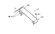
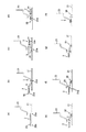
図11に示すような、一端部20aがZ字状に折曲され他端部20bがU字状に折曲されるようにループ材20を縫製物本体21に縫い付ける場合の工程を図12(a)〜(h)に示す。先ず前述のループ材供給装置は、ループ材20の長手方向の一端部20a近傍を挟持した状態の挟持手段3を、ループ材20の一端部20aがミシンの縫製位置に位置するように移動する(図12(a))。この移動中は、ループ材20の供給位置がずれないように、ループ材20における挟持手段3のループ挟持位置が移動しない必要がある。
The process in the case of sewing the
そして、ミシンの押さえ23が下降しループ材20の一端部20aが押さえられると、ループ材供給装置は、挟持手段3を一端部20aの左上の方向(図12(b)矢印A方向)へ移動させ、縫製位置から離間させる。この移動に合わせて、ループ材20を挟持手段3に対して滑らせることにより、ループ材20における挟持手段3のループ挟持位置が、ループ材の一端部20aの近傍から他端部20bの近傍に移動する。(図12(b))この状態で、ミシンは、ループ材20の一端部20aを縫製物本体21に縫い付ける(第1の縫製)。この第1の縫製中に縫製物本体21および押さえ23は縫い目の形成方向に移動するが、挟持手段3は同方向に移動不可能なため、挟持手段3に挟持されたループ材20が縫製物本体21を引っ張り縫製物本体21がしわになることを防ぐためには、ループ材20が挟持手段3に対して適度に滑り、ループ材20における挟持手段3のループ挟持位置が移動することにより、ループ材20が縫製物本体21とともに移動する必要がある。
When the
第1の縫製後、ループ材供給装置は押さえ23を上昇し、他端部20bを挟持した挟持手段3を、右方向(図12(c)矢印B方向)に、第1の縫製による縫い目(第1の縫い目)を越えて移動させる(図12(c))。これにより、ループ材20は、第1の縫い目を覆うように折り返される。この移動間もループ材20は挟持手段3に対してわずかに滑ることでループ挟持位置を移動することにより、ループ材20の移動に伴い縫製された一端部20aが縫製物本体21を引張り、縫製物本体21がしわになることを防止する必要がある。
After the first sewing, the loop material supply device raises the
次にミシンは、挟持手段3を下降させ、ループ材20を縫製物本体21に重ねる。さらに、ループ材20の一端部20aの近傍上面に押さえ23を下降し、ループ材20を押付けた後、第2の縫製を行うことにより、第1の縫い目の近傍(図12(d)における第1の縫い目の右側)に第2の縫い目を形成する(図12(d))。そして、再び押さえ23を上昇した後、挟持手段3は再び一端部20aの左上の方向(図12(e)矢印C方向)へ移動する(図12(e))。これにより、ループ材20は第2の縫い目を覆うように折り返され、一端部20aはZ字状に折曲される。この移動間もループ材20は挟持手段3に対してわずかに滑ることでループ挟持位置を移動することにより、ループ材20の移動に伴い縫製された一端部20aが縫製物本体21を引張り、縫製物本体21がしわになることを防止する必要がある。
Next, the sewing machine lowers the clamping means 3 and puts the
続いてミシンは、フォーク部材25が備える一対の支持部25aによって、挟持手段3が挟持するすぐ右側のループ材20の他端部20bの近傍を挟み(図12(f))、ループ材20の他端部がU字状に折曲されるようにフォーク部材25を回転する(図12(g))。フォーク部材25が回転する際に挟持手段3がループ材20を挟持する挟持圧が弱過ぎると、ループ材20が弛んだり、ループ材20が挟持手段3から外れる場合がある。フォーク部材25の回転の終了直前には、ループ材20は挟持手段3に対して滑り、挟持手段3から解放される(図12(g))。このとき挟持手段3のループ材20に対する挟持圧が強過ぎると、ループ材が解放されない場合がある。
Subsequently, the sewing machine sandwiches the vicinity of the
そして、ミシンは、フォーク部材25をループ材20の他端部20bの近傍から抜き取り、ループ材20の他端部20bの近傍を押さえ23によって押さえて縫い付けることにより、ループ材20を縫製物本体21に縫い付けるようになっている(第3の縫製)(図12(h))。
The sewing machine extracts the
前述したように、ループ材20をミシンに供給する各供給工程では、各供給工程によりループ材20が移動、縫製される際にループ材20における挟持手段2のループ挟持位置が移動する必要がある場合と、移動しない必要がある場合がある。また、フォーク部材25がループ材20を挟持して回転する場合は、その回転の初期には、挟持手段3がループ材20の挟持を保つ必要があるが、フォーク部材25の回転の終了直前にはループ材20は挟持手段3から解放される必要がある。
As described above, in each supply process of supplying the
ここで、ループ材20における挟持手段3のループ挟持位置が移動するか否か、また挟持手段3がループ材20の挟持を保つか、解放するかは、挟持手段3がループ材20を挟持する圧力である挟持圧により決まるが、従来のループ材供給装置では挟持手段3の挟持圧が一定のため、前述した各供給工程における最適な挟持圧を提供できなかった。
Here, whether or not the loop clamping position of the clamping means 3 in the
このため、ループ材20を縫製物本体21に縫い付けるためのミシンの縫製動作中に、挟持手段3のループ材20に対する挟持圧が弱いと、挟持手段3によるループ材20の挟持が外れてしまうおそれがあるという問題を有していた。
For this reason, if the clamping pressure with respect to the
一方、挟持手段3によるループ材20に対する挟持圧が強いと、挟持手段3によりループ材20を挟持した状態でそのループ挟持位置を移動する際に、ループ材20を縫い付ける縫製物本体21を引っ張り、しわにしてしまうおそれがあるという問題を有していた。
On the other hand, when the clamping pressure on the
また、ループ材20の他端部20bをU字状に折曲するためにフォーク部材25が回転する際、フォーク部材25の回転開始から回転直後は、挟持手段3による挟持圧が強くないと、挟持手段3によるループ材20の挟持が外れてしまい、ループ材20の他端部20bをU字状に折曲することができない場合があった。一方、フォーク部材25の回転終了の直前は、挟持手段3による挟持圧が弱くないと、挟持手段3からループ材20が外れず、フォーク部材25を確実に回転させることができなかったり、あるいは、フォーク部材25に絡んだループ材20によって縫製物本体21を引っ張ってしまうという問題を有していた。
Further, when the
また、ループ材20の厚みや材料の腰の強さなどが異なると、最適な挟持圧も異なり、設定されていた挟持圧ではループ材20を確実に供給できないという問題があった。
Further, when the thickness of the
このような結果、ループ材20を縫い付ける縫製物本体21にしわが発生したり、意図した位置にループ材20を縫い付けることができず、縫製不良が発生してしまう場合があるという問題を有していた。
As a result, there is a problem that wrinkles may occur in the sewn product
本発明はこれらの点に鑑みてなされたものであり、ループ材を縫い付ける縫製物本体にしわが発生するのを防止することができるとともに、意図した位置にループ材を確実に供給することにより、ループ材を縫製物本体に縫い付けた場合の縫製不良の発生を防止することができるループ材供給装置を提供することを目的とする。 The present invention has been made in view of these points, and can prevent wrinkles from occurring in the sewn product body to which the loop material is sewn, and by reliably supplying the loop material to the intended position, It is an object of the present invention to provide a loop material supply device capable of preventing the occurrence of poor sewing when a loop material is sewn to a sewn product body.
前記目的を達成するため、請求項1に記載の発明に係るループ材供給装置の特徴は、ベルトループを構成するループ材を挟持する挟持手段と、前記ループ材の各縫製箇所を縫製物本体に対して移動させるために前記挟持手段を移動する移動手段と、少なくとも前記挟持手段および前記移動手段の制御を行う制御手段とを備えたベルトループ縫い付けミシンのループ材供給装置において、前記挟持手段がループ材を挟持する挟持圧を変更する挟持圧変更手段を備え、前記制御手段は、さらにループ材を前記ベルトループ縫い付けミシンに供給する各供給工程に応じて前記挟持圧変更手段に前記挟持圧を設定する制御を行う点にある。
供給の各供給工程に応じて挟持圧変更手段に挟持圧を設定する制御を行うので、前記各供給工程において最適な挟持圧を提供することが可能となる。これにより、ループ材供給装置は、ミシンの縫製動作中に、挟持手段によるループ材の挟持が外れてしまうことを防止することができ、特に腰が強い素材によって構成されたループ材を用いる場合に、ループ材が挟持手段による挟持から外れて弛んでしまうのを防止することができる。これとともに、挟持手段によってループ材を挟持しながら挟持手段によるループ挟持位置を移動するときに、ループ材が挟持手段に対して円滑に滑ることができるので、ループ材が縫製物本体を引っ張りしわにしてしまうことを防止することができる。
In order to achieve the above object, a feature of the loop material supply device according to the first aspect of the present invention is that the loop material constituting the belt loop is sandwiched by means for clamping, and each sewing point of the loop material is attached to the sewing product body. In a loop material supply device for a belt loop sewing machine comprising: moving means for moving the holding means to move the belt; and control means for controlling at least the holding means and the moving means. A clamping pressure changing means for changing a clamping pressure for clamping the loop material is provided, and the control means further applies the clamping pressure to the clamping pressure changing means in accordance with each supply step of supplying the loop material to the belt loop sewing machine. The point is to perform control to set the.
Since the control for setting the clamping pressure in the clamping pressure changing means is performed according to each supply process of supply, it is possible to provide an optimal clamping pressure in each of the supply processes. Thereby, the loop material supply device can prevent the holding of the loop material by the holding means during the sewing operation of the sewing machine, and in particular, when using a loop material made of a strong material. It is possible to prevent the loop material from coming loose from being pinched by the pinching means and being loosened. At the same time, when moving the loop clamping position by the clamping means while holding the loop material by the clamping means, the loop material can smoothly slide with respect to the clamping means, so that the loop material pulls the sewn product main body. Can be prevented.
請求項2に記載の発明に係るループ材供給装置の特徴は、請求項1に記載の発明に係るループ材供給装置において、前記ループ材が移動、縫製される際に、前記ループ材における前記挟持手段が挟持するループ挟持位置が、少なくとも移動可能な状態と、移動不可能な状態とに、前記制御手段による前記挟持圧を設定可能とした点にある。
The loop material supply device according to
この請求項2に記載の発明によれば、ループ材供給装置は、ミシンの縫製動作中に、挟持手段によるループ材の挟持が外れてしまうことを確実に防止することができ、特に腰が強い素材によって構成されたループ材を用いる場合に、ループ材が挟持手段による挟持から外れて弛んでしまうのを防止することができる。これとともに、挟持手段によってループ材を挟持しながら挟持手段によるループ挟持位置を移動するときに、ループ材が挟持手段に対して円滑に滑ることができるので、ループ材を縫い付ける縫製物本体を引っ張りしわにしてしまうことを確実に防止することができる。 According to the second aspect of the present invention, the loop material supply device can reliably prevent the loop material from being pinched by the pinching means during the sewing operation of the sewing machine, and is particularly strong. In the case of using a loop material made of a material, it is possible to prevent the loop material from coming loose from being pinched by the pinching means and being loosened. At the same time, when moving the loop clamping position by the clamping means while holding the loop material by the clamping means, the loop material can smoothly slide with respect to the clamping means. Wrinkles can be reliably prevented.
請求項3に記載の発明に係るループ材供給装置の特徴は、請求項1または請求項2に記載の発明に係るループ材供給装置において、前記ループ材が移動、縫製される際に、前記ループ材における前記ループ挟持位置が移動可能な状態において、前記制御手段はさらに、前記挟持手段に対する前記ループ材の移動速度、移動量を調整可能とするように前記挟持圧を設定可能とした点にある。
A feature of the loop material supply device according to the invention described in
この請求項3に記載の発明によれば、ループ材供給装置は、ミシンの縫製動作中に、挟持手段によるループ材の挟持が外れてしまうことをより確実に防止することができ、特に腰が強い素材によって構成されたループ材を用いる場合に、ループ材が挟持手段による挟持から外れて弛んでしまうのを防止することができる。これとともに、挟持手段によってループ材を挟持しながら挟持手段によるループ挟持位置を移動するときに、ループ材が挟持手段に対して円滑に滑ることができるので、ループ材を縫い付ける縫製物本体を引っ張りしわにしてしまうことをより確実に防止することができる。 According to the third aspect of the present invention, the loop material supply device can more reliably prevent the loop material from being held by the holding means during the sewing operation of the sewing machine. When a loop material made of a strong material is used, it is possible to prevent the loop material from coming loose from being pinched by the pinching means. At the same time, when moving the loop clamping position by the clamping means while holding the loop material by the clamping means, the loop material can smoothly slide with respect to the clamping means. Wrinkles can be more reliably prevented.
さらに、請求項4に記載の発明に係るループ材供給装置の特徴は、請求項1乃至請求項3のいずれか1項に記載の発明に係るループ材供給装置において、フォーク部材が備えた一対の支持部によって前記ループ材の端部を挟持し、前記フォーク部材を回転することにより、前記ループ材の端部を折曲するとともに前記端部を前記挟持手段から外す工程において、前記制御手段は、前記フォーク部材の回転終了直前における前記挟持手段の前記挟持圧が、前記両支持部が前記ループ材を挟む際の前記挟持手段の前記挟持圧と比較して弱くなるように制御する点にある。 Further, the loop material supply device according to the invention described in claim 4 is characterized in that the pair of fork members provided in the loop material supply device according to any one of claims 1 to 3 is provided. In the step of bending the end portion of the loop material and removing the end portion from the clamping means by sandwiching the end portion of the loop material by a support portion and rotating the fork member, the control means includes: The clamping pressure of the clamping means immediately before the end of the rotation of the fork member is controlled so as to be weaker than the clamping pressure of the clamping means when the both support portions clamp the loop material.
この請求項4に記載の発明によれば、フォーク部材の回転終了直前における挟持圧を、両支持部がループ材を挟む際の前記挟持手段の挟持圧と比較して弱くすることにより、ループ材を挟持手段から容易に外すことができる。また、両支持部がループ材を挟むときの挟持圧を、フォーク部材の回転終了直前の挟持圧より強くすることにより、ループ材が弛んでしまったり、挟持手段から外れてしまうのを防止することができる。これにより、ループ材供給装置は、意図した位置にループ材を確実に供給することができるので、ミシンは、ループ材を縫製物本体に縫い付けた場合の縫製不良の発生を防止し、高品質のループ材を縫製物本体に縫い付けることができる。 According to the fourth aspect of the present invention, by reducing the clamping pressure immediately before the end of the rotation of the fork member as compared with the clamping pressure of the clamping means when both support parts clamp the loop material, the loop material Can be easily removed from the clamping means. Also, by making the holding pressure when both support parts hold the loop material stronger than the holding pressure just before the end of the rotation of the fork member, it is possible to prevent the loop material from loosening or coming off from the holding means. Can do. As a result, the loop material supply device can reliably supply the loop material to the intended position, so that the sewing machine prevents the occurrence of poor sewing when the loop material is sewn to the body of the sewing product, resulting in high quality. Loop material can be sewn to the sewing body.
さらにまた、請求項5に記載の発明に係るループ材供給装置の特徴は、請求項1または請求項4に記載の各発明に係るループ材供給装置において、前記各供給工程に応じて設定された前記挟持圧の値が記憶された記憶手段を備えた点にある。
Furthermore, the characteristics of the loop material supply device according to the invention described in
この請求項5に記載の発明によれば、各供給工程に応じて、記憶手段に記憶された挟持圧によって挟持手段によりループ材を挟持することにより、各供給工程に最適な挟持手段によるループ材の挟持条件を提供することができる。
According to the invention described in
また、請求項6に記載の発明に係るループ材供給装置の特徴は、請求項5に記載の発明に係るループ材供給装置において、前記記憶手段に記憶される前記挟持圧の値を入力可能な操作手段を備えた点にある。
The loop material supply device according to claim 6 is characterized in that, in the loop material supply device according to
この請求項6に記載の発明によれば、操作手段を操作することにより、記憶手段に記憶された挟持圧を任意の圧力値に変更することができるようになっている。これにより、操作者は、例えばループ材の材質等の種々の条件を考慮して挟持圧値を変更することができるので、ループ材におけるループ挟持位置をより円滑に移動して縫製物本体の引きつれを確実に防止することができるとともに、ループ材の弛みを防止して、より確実に意図した位置にループ材を供給することができる。 According to the sixth aspect of the present invention, the clamping pressure stored in the storage means can be changed to an arbitrary pressure value by operating the operating means. As a result, the operator can change the clamping pressure value in consideration of various conditions such as the material of the loop material, for example, so that the loop clamping position in the loop material can be moved more smoothly to pull the sewn product main body. It is possible to reliably prevent the slipping and to prevent the loop material from slacking, and to supply the loop material to the intended position more reliably.
さらに、請求項7に記載の発明に係るループ材供給装置の特徴は、請求項5または請求項6に記載の発明に係るループ材供給装置において、前記挟持手段によって挟持される前記ループ材の厚さ寸法を検出する検出手段を備えており、前記制御手段は、前記記憶手段に記憶された前記挟持圧の値を、前記検出手段により検出された前記ループ材の厚さ寸法を考慮して算出された前記挟持圧の値に補正する点にある。
Further, the loop material supply device according to the invention described in claim 7 is characterized in that in the loop material supply device according to
この請求項7に記載の発明によれば、検出手段によって、挟持手段により挟持されるループ材の厚さ寸法を検出し、記憶手段に記憶された挟持圧を検出された厚さ寸法を考慮して算出された最適の挟持圧に補正することができる。これにより、挟持手段によってループ材を挟持しながら挟持手段によるループ挟持位置を移動するときに、ループ材が挟持手段に対して円滑に滑ることができるので、ループ材を縫い付ける縫製物本体を引っ張ってしまうことを確実に防止することができるとともに、ループ材の弛みを防止して、より確実に意図した位置にループ材を供給することができる。 According to the seventh aspect of the present invention, the detecting means detects the thickness dimension of the loop material that is clamped by the clamping means, and takes into account the detected thickness dimension of the clamping pressure stored in the storage means. It is possible to correct the optimum clamping pressure calculated in the above. As a result, when the loop material is moved by the clamping means while the loop material is being clamped by the clamping means, the loop material can smoothly slide with respect to the clamping means, so that the sewn body to which the loop material is sewn is pulled. It is possible to reliably prevent the loop material from being loosened, and to prevent the loop material from slackening, so that the loop material can be more reliably supplied to the intended position.
さらにまた、請求項8に記載の発明に係るループ材供給装置の特徴は、請求項1乃至請求項7に記載の発明に係るループ材供給装置において、前記挟持圧変更手段は、電空レギュレータである点にある。 Furthermore, the loop material supply device according to the invention described in claim 8 is characterized in that in the loop material supply device according to claims 1 to 7, the clamping pressure changing means is an electropneumatic regulator. There is a point.
この請求項8に記載の発明によれば、挟持圧変更手段として電空レギュレータを用いることにより、挟持手段によるループ材に対する挟持圧を各供給工程に応じて確実に変更することができる。 According to the eighth aspect of the invention, by using the electropneumatic regulator as the clamping pressure changing means, the clamping pressure on the loop material by the clamping means can be reliably changed according to each supply process.
また、請求項9に記載の発明に係るループ材供給装置の特徴は、請求項1乃至請求項7に記載の発明に係るループ材供給装置において、前記挟持圧変更手段は、設定圧力が固定された複数の減圧弁が組み込まれた空圧回路である点にある。
The loop material supply device according to the invention described in
この請求項9に記載の発明によれば、挟持圧変更手段として空圧回路を用いることにより、挟持手段によるループ材に対する挟持圧を各供給工程に応じて確実に変更することができる。 According to the ninth aspect of the present invention, by using the pneumatic circuit as the clamping pressure changing means, the clamping pressure on the loop material by the clamping means can be reliably changed according to each supply process.
以上述べたように、本発明に係るループ材供給装置によれば、挟持手段によってループ材を挟持しながら挟持手段によるループ挟持位置を移動するときに、ループ材が挟持手段に対して円滑に滑ることができるので、ループ材が縫製物本体を引っ張りしわにしてしまうのを防止することができる。また、ループ材供給装置は、ループ材の弛みを防止することができるので、意図した位置にループ材を確実に供給することができる。この結果、このループ材供給装置によってループ材を供給されるミシンにおいては、ループ材を縫製物本体に縫い付けた場合の縫製不良の発生を防止し、高品質のループ材を縫製物本体に縫い付けることができる。 As described above, according to the loop material supply device of the present invention, the loop material smoothly slides with respect to the clamping means when the loop material is moved by the clamping means while the loop material is being clamped by the clamping means. Therefore, it is possible to prevent the loop material from pulling and wrinkling the sewn product main body. Further, since the loop material supply device can prevent the loop material from slackening, the loop material can be reliably supplied to the intended position. As a result, in the sewing machine that is supplied with the loop material by the loop material supply device, it is possible to prevent the occurrence of poor sewing when the loop material is sewn to the sewn product body, and the high-quality loop material is sewn to the sewn product body. Can be attached.
以下、本発明に係るループ材供給装置の一実施形態を図1から図10を参照して説明する。ここで、従来のループ材供給装置と同一の構成については、同一の符号を用いて説明する。 Hereinafter, an embodiment of a loop material supply device according to the present invention will be described with reference to FIGS. Here, the same components as those of the conventional loop material supply device will be described using the same reference numerals.
図1は、本実施形態に係るループ材供給装置およびこのループ材供給装置によって供給されるループ材を縫製物本体に縫い付けるミシンとループ供給装置を示す斜視図、図2は、図1のループ材供給装置の要部を示す拡大斜視図である。 FIG. 1 is a perspective view showing a loop material supply device according to the present embodiment, a sewing machine for sewing the loop material supplied by the loop material supply device to a sewing product body, and the loop supply device. FIG. It is an expansion perspective view which shows the principal part of a material supply apparatus.
図1および図2に示すように、本実施形態に係るループ材供給装置1は、ミシン2にベルトループを構成するループ材20を供給するためにループ材20を挟持する挟持手段3を有している。
As shown in FIGS. 1 and 2, the loop material supply device 1 according to the present embodiment has a clamping means 3 for clamping the
挟持手段3は、ループ材20の上面に当接する第1挟持部材5と、ループ材20の下面に当接する第2挟持部材6とを備え、第1挟持部材5および第2挟持部材6によってループ材20を挟持するようになっている。第1挟持部材5は、平板状に形成された支持部5aと、支持部5aの先端部において第2挟持部材6の方向である下方に突出して形成された押圧部5bと、支持部5aの他端部に立設される取付部5cとを備え、側面形状がL字状に形成されている。支持部5aの上面には、補助部材5dが固定ねじ5eによって取り付けられており、補助部材5dの先端部は、押圧部5bの先端側に位置し、第2挟持部材6の方向に突出して形成され、押圧部5bとともにループ材20を押さえるようになっている。そして、補助部材5dは、先端部が押圧部5bの先端側から突出する方向に延出可能に取り付けられている。
The clamping means 3 includes a
第2挟持部材6は、平板状に構成され、第1挟持部材5における押圧部5bおよび補助部材5dの先端部の下面に対向するように配置されており、第2挟持部材6の一端部6aは、第1挟持部材5の下方に配置された平板状のフレーム部材7に固定されている。
The 2nd clamping member 6 is comprised by flat form, and is arrange | positioned so that the press part 5b in the
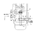
挟持手段3には、第1挟持手段5と第2挟持手段6とを相互に接離する方向に駆動する駆動手段としてエアシリンダ9が取り付けられており、エアシリンダ9のシリンダ本体9aは、第1挟持手段3における取付部5cに取り付けられ、エアシリンダ9のシリンダロッド9bの先端部は、フレーム部材7の上面に取り付けられている。
An
図3に示すように、エアシリンダ9は、エアシリンダ9に圧力を供給するための空圧回路11に連結されている。この空圧回路11は、電気信号によりエアシリンダ9に供給する圧力を調整可能な電空レギュレータ12と、シリンダロッド9bの移動方向を選択する3方弁13と、エア供給源からの元圧を適切な圧力に変換して3方弁13および電空レギュレータ12に供給するための減圧弁15とを有している。
As shown in FIG. 3, the
エアシリンダ9は、シリンダロッド9bをシリンダ本体9aの内部へ引き込んだ状態で、図2に示すように、第1挟持部材5が第2挟持部材6の方向に移動し、ループ材20を挟持するようになっている。このとき、減圧弁15、電空レギュレータ12、3方弁13、および各移動機構等のループ材供給装置1の各部の駆動を制御する制御手段17が、電空レギュレータ12を制御することによりエアシリンダ9へのエア供給圧力を調整し、挟持手段3によるループ材20に対する挟持圧を設定することができるようになっている。
In the
さらに、制御手段17は、ループ材20が移動、縫製される際には、ループ挟持位置が移動可能な状態であって、さらに挟持手段3に対するループ材20の移動速度、移動量を調整するように挟持圧を設定することができるようになっている。
Furthermore, when the
また、ループ材供給装置1は、ループ材20の縫製箇所をミシン2の縫製位置に供給したり、ループ材20の非縫製箇所を前記縫製位置から退避させるように挟持手段3を移動する移動機構16を有している。ループ材供給装置1は、この移動機構16として、図5に示すように、挟持手段3をループ材20を縫製物本体21に縫い付ける時に形成される縫い目に沿った方向(図6におけるD)に移動する横方向移動機構16b(16)と、挟持手段3を縫い目と直交する方向(図6におけるE)に移動する縦方向移動機構16a(16)と、挟持手段3を縫製物本体に対して上下方向に移動する上下方向移動機構16c(16)とを備えている。
Further, the loop material supply device 1 supplies a sewing part of the
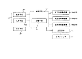
さらに、ループ材供給装置1の制御手段17は、ループ材供給装置1の各動作のプログラム等を記憶する記憶手段18を備えている。そして、制御手段17は、記憶手段18に記憶されたプログラムに基づき、ループ材20における縫製箇所をミシン2の縫製位置に供給するように各移動機構16を駆動して挟持手段3を移動するようになっている。また、制御手段17は、ミシン2による縫製動作が開始されると、挟持手段3によってループ材20を挟持しながら挟持手段3によるループ挟持位置を移動したり、ループ材20の両端部20a、20bが所望の形状に折曲されるようにループ材20の各縫製箇所を供給するように、移動機構16を駆動して挟持手段3を移動するようになっている。
Further, the control means 17 of the loop material supply apparatus 1 includes a storage means 18 for storing a program of each operation of the loop material supply apparatus 1 and the like. Based on the program stored in the storage means 18, the control means 17 drives each moving
そして、制御手段17は、ループ材20が所定の形状によって縫製物本体21に縫い付けられるように、挟持手段3によって挟持したループ材20の各縫製箇所をミシン2における縫製位置に供給する工程において、挟持手段3の挟持圧を変更する挟持圧変更手段としての電空レギュレータ12を制御することにより、エアシリンダ9へのエア供給圧力を調整し、両挟持部材5、6による挟持圧を制御するようになっている。本実施形態においては、ループ材20が移動、縫製される際に、ループ材20におけるループ挟持位置が、少なくとも移動可能な状態と、移動不可能な状態とに、制御手段17による挟持圧を設定可能とされている。また、本実施形態においては、制御手段17は、挟持手段3によるループ材20に対する挟持圧を、挟持手段3によるループ挟持位置が移動するように挟持手段3を移動する際の挟持手段3の移動開始から移動停止直前までの挟持圧が、挟持手段3の移動停止直前から挟持手段3の移動停止中における挟持圧と比較して弱くなるように制御する。
Then, the control means 17 supplies each sewing location of the
続いて、ループ材供給装置1によって背景技術において記載したような一端部20aがZ字状に折曲され他端部20bがU字状に折曲される形状にループ材20をミシン2の縫製位置に供給し、ミシン2によってループ材20を縫製物本体21に縫い付ける場合を用いて説明する(図11、図12(a)〜(h)参照)。
Subsequently, the
まず、ループ材供給装置1は、制御手段17において各移動機構16を駆動することにより、ループ材20における長手方向の一端部20aの近傍を挟持した状態の挟持手段3を、ループ材20の一端部20aがミシンの縫製位置に位置するように移動する。このとき、図7に示すように、制御手段17は、電空レギュレータ12を制御することによりエアシリンダ9へのエア供給圧力を調整し、挟持手段3によるループ材20に対する挟持圧を、挟持手段3によるループ挟持位置が移動不可能な所定の圧力値(本実施形態においてはこの所定の圧力値を基準圧力値という)に制御する。
First, the loop material supply device 1 drives each moving
そして、ミシンの押さえ23が下降しループ材20の一端部20aが押さえられると、制御手段17は、電空レギュレータ12を制御することによりエアシリンダ9へのエア供給圧力を調整し、挟持圧が基準圧力値よりも弱く、挟持手段3によるループ挟持位置が移動可能な圧力値(本実施形態においてはこの圧力値を弱圧力値という)となるように制御する。この挟持手段3による挟持圧が弱圧力値の状態で、制御手段17は、挟持手段3を一端部20aの左上の方向(図8(b)の矢印A方向)へ移動させる。この移動に合わせて、ループ材20を挟持手段3に対して滑らせることにより、ループ材20における挟持手段3のループ挟持位置が、ループ材20の一端部20aの近傍から他端部20bの近傍に移動する。
When the
続いて、制御手段17は、挟持手段3の移動が停止する直前に、挟持圧が弱圧力値よりも強く、基準圧力値よりも弱い圧力値(本実施形態においてはこの圧力値を中圧力値という)となるように制御する。この状態で、ミシン2は、ループ材20の一端部20aを縫製物本体21に縫い付ける(第1の縫製)。制御手段17は、この第1の縫製中、挟持手段3による挟持圧を中圧力値の状態に維持する。第1の縫製中に縫製物本体21および押さえ23は縫い目の形成方向に移動するが、同方向に移動不可能な挟持手段3に挟持されているループ材20は、挟持圧が中圧力値の状態では挟持手段3に対して適度に滑り、ループ挟持位置が変化する。
Subsequently, the control means 17 immediately before the movement of the clamping means 3 stops, the clamping pressure is higher than the weak pressure value and weaker than the reference pressure value (in this embodiment, this pressure value is set to the medium pressure value). Control). In this state, the
第1の縫製後、ループ材供給装置1は、押さえ23を上昇し、ループ材20の一端部20aよりも少しループ材20の長さ方向における中央側である一端部20aの近傍がミシン2の縫い位置に位置するように、ループ材20が縫い付けられた縫製物本体21を搬送する。このとき、ループ材供給装置1の制御手段17は、挟持圧を弱圧力値となるように制御し、他端部20bを挟持した挟持手段3を、第1の縫製による縫い目(第1の縫い目)を越えて移動させる。これにより、ループ材20は、第1の縫い目を覆うように折り返される。この挟持手段3の移動の間、ループ材20は挟持手段3に対してわずかに滑ることでループ挟持位置が一端部20aの際端部側に移動する。
After the first sewing, the loop material supply device 1 raises the
さらに、制御手段17は、挟持手段3の移動が停止する直前に、挟持手段3の挟持圧を中圧力値となるように制御した後、挟持手段3を下降させて、ループ材20を縫製物本体21に重ねる。さらに、ループ材20の一端部20aの近傍上面に押さえ23を下降してループ材20を押付け、第2の縫製を行い、第1の縫い目の近傍に第2の縫い目を形成する。制御手段17は、ミシン2がループ材20の一端部20aの近傍を押さえ23によって押さえて縫製物本体21に縫い付ける縫製動作中、この挟持手段3による挟持圧を中圧力値の状態に維持する。第2の縫製中も第1の縫製中と同様に、挟持手段3がループ材20を挟持するループ挟持位置は変化する。
Furthermore, the control means 17 controls the clamping pressure of the clamping means 3 to be an intermediate pressure value immediately before the movement of the clamping means 3 is stopped, and then lowers the clamping means 3 so that the
続いて、第2の縫製後、ミシン2は、再び押さえ23を上昇した後、ループ材20の他端部20bの近傍が縫製位置に位置するようにループ材20が縫い付けられた縫製物本体21を搬送する。また、ループ材供給装置1の制御手段17は、挟持圧を弱圧力値となるように制御した後、挟持手段3を移動して第2の縫い目を覆われるようにループ材20を折り返し、一端部20aをZ字状に折曲する。この移動の間も、ループ材20が挟持手段3に対してわずかに滑ることにより、ループ挟持位置を移動する。
Subsequently, after the second sewing, the
そして、制御手段17は、挟持手段3の移動が停止する直前に、挟持手段3の挟持圧を中圧力値となるように制御した後、挟持手段3の移動を停止する。さらに、制御手段17は、軸方向に並列して配置された一対の支持部25aを備えるフォーク部材25をループ材20の幅方向に移動し、両支持部25aがループ材20の両平面に位置するようにループ材20を挟む直前に、挟持圧が基準圧力値となるように制御する。
Then, the control means 17 controls the clamping pressure of the clamping means 3 to be an intermediate pressure value immediately before the movement of the clamping means 3 stops, and then stops the movement of the clamping means 3. Furthermore, the control means 17 moves the
その後、制御手段17は、挟持手段3の挟持圧が基準圧力値の状態で、ループ材20の他端部がU字状に折曲されるようにフォーク部材25を回転し、フォーク部材25の回転が終了する直前に、挟持手段3の挟持圧を弱圧力値となるように制御する。このとき、ループ材20は挟持手段3に対して滑り、挟持手段3から解放される。
Thereafter, the control means 17 rotates the
そして、ミシン2は、フォーク部材25をループ材20の他端部20bの近傍から抜き取り、ループ材20の他端部20bの近傍を押さえ23によって押さえて縫い付けることにより、ループ材20を縫製物本体21に縫い付けるようになっている(第3の縫製)。第3の縫製動作中、制御手段17は、次のループ材20の供給動作に備えるため、各移動機構16の駆動によってループ材20を挟持する位置に挟持手段3を移動する。
The
前記基準圧力値、弱圧力値および中圧力値は、予め実験等により求められたループ材20の各供給工程に応じた最適な圧力値に設定されており、記憶手段18に記憶されている。そして、制御手段17は、前述のように、各供給の工程に応じて、記憶手段18に記憶された挟持圧によって電空レギュレータ12を制御することによりエアシリンダ9へのエア供給圧力を調整して、挟持手段3によりループ材20を挟持することができる。
The reference pressure value, the weak pressure value, and the intermediate pressure value are set to optimum pressure values corresponding to each supply process of the
また、ループ材供給装置1は、制御手段17にループ材供給装置1の各部の操作の指示を入力する操作手段27を有しており、この操作手段27は、操作に関する情報を表示する表示手段28と、入力手段29とを備えている。そして、操作手段27は、操作者の操作によって、記憶手段18に記憶された挟持圧を変更する指示を制御手段17に入力することができるようになっている。 Further, the loop material supply apparatus 1 has an operation means 27 for inputting an operation instruction of each part of the loop material supply apparatus 1 to the control means 17, and this operation means 27 is a display means for displaying information related to the operation. 28 and input means 29 are provided. The operation means 27 can input an instruction to change the clamping pressure stored in the storage means 18 to the control means 17 by the operation of the operator.
さらに、ループ材供給装置1には、挟持手段3によって挟持されているループ材20の厚さ寸法を検出する検出手段30が設けられており、制御手段17は、検出手段30から入力されたループ材20の厚さ寸法を考慮して、記憶手段18に記憶されている挟持圧を補正することができるようになっている。
Further, the loop material supply device 1 is provided with a detecting
次に、本実施形態の作用について説明する。 Next, the operation of this embodiment will be described.
本実施形態によれば、挟持手段3によって挟持したループ材20の各縫製箇所をミシン2における縫製位置に供給する各供給工程に応じて、制御手段17からの指令によって電空レギュレータ12(挟持圧変更手段)に挟持圧を設定することにより、両挟持部材5、6による挟持圧を制御することができるので、前記各供給工程において最適な挟持圧を提供することが可能となる。これにより、ループ材供給装置1は、ミシン2の縫製動作中に、挟持手段3によるループ材20の挟持が外れてしまうことを防止することができ、特に腰が強い素材によって構成されたループ材20を用いる場合に、ループ材20が挟持手段3による挟持から外れて弛んでしまうのを防止することができる。これとともに、挟持手段3によってループ材20を挟持しながら挟持手段3によるループ挟持位置を移動するときに、ループ材20が挟持手段3に対して滑るので、ループ材20が縫製物本体21を引っ張り、しわにしてしまうことを防止することができる。
According to the present embodiment, the electropneumatic regulator 12 (clamping pressure) according to a command from the control unit 17 in accordance with each supply process of supplying each sewing location of the
したがって、ループ材20の縫い付け中にループ材20の弛みを防止することにより、意図した位置にループ材20を確実に供給することができる。この結果、このループ材供給装置1によってループ材20を供給されるミシン2においては、ループ材20を縫製物本体21に縫い付けた場合の縫製不良の発生を防止し、高品質のループ材20を縫製物本体21に縫い付けることができる。
Therefore, the
また、ループ材供給装置1においては、挟持手段3によるループ挟持位置が、少なくとも移動可能な状態と移動不可能な状態とに、制御手段17による挟持圧を設定可能としたことにより、挟持手段3によるループ挟持位置をより円滑に移動することができるとともに、ループ材20の縫い付け中にはループ材20の弛みを確実に防止することができる。
Further, in the loop material supply device 1, the holding pressure by the control means 17 can be set so that the loop holding position by the holding means 3 is at least movable and non-movable. It is possible to more smoothly move the loop clamping position due to the above, and it is possible to reliably prevent the
さらに、ループ材供給装置1は、制御手段17により、ループ材20が移動、縫製される際に、ループ挟持位置が移動可能な状態であって、さらに挟持手段3に対するループ材20の移動速度、移動量を調整するように挟持圧を設定することにより、ループ材20を供給する各供給工程において最適な挟持圧を提供することが可能となる。挟持手段3によるループ挟持位置をより円滑に移動することができるとともに、ループ材20の縫い付け中にはループ材20をしっかり挟持してループ材20の弛みをより確実に防止することができる。
Furthermore, the loop material supply device 1 is in a state where the loop clamping position can be moved when the
さらにまた、フォーク部材25の回転終了直前における挟持圧を、両支持部25aがループ材20を挟む際の挟持圧と比較して弱くすることにより、ループ材20を挟持手段3から容易に外すことができる。また、両支持部25aがループ材20を挟むときの挟持圧を、フォーク部材25の回転終了直前の挟持圧より強くすることにより、ループ材20の縫い付け中にループ材が弛んでしまったり、挟持手段3から外れてしまうのを防止することができる。これにより、ループ材供給装置1は、意図した位置にループ材20を確実に供給することができるので、ミシン1は、ループ材20を縫製物本体21に縫い付けた場合の縫製不良の発生を防止し、高品質のループ材20を縫製物本体21に縫い付けることができる。
Furthermore, the
さらに、記憶手段18には、ループ材供給装置1によるループ材20の各供給工程に応じた最適の挟持圧が記憶されているので、ループ材供給装置1は、各供給工程に応じて、記憶手段18に記憶された挟持圧によって挟持手段3によりループ材20を挟持することにより、各工程に最適な、挟持手段によるループ材の挟持条件を提供することができる。
Further, since the optimum clamping pressure corresponding to each supply process of the
さらにまた、ループ材供給装置1においては、操作手段27を操作することにより、記憶手段18に記憶された挟持圧を任意の圧力値に変更することができるようになっている。これにより、操作者は、例えばループ材20の材質等の種々の条件を考慮して挟持圧を変更することができるので、挟持手段3によるループ挟持位置をより円滑に移動して縫製物本体21がしわになることを確実に防止することができるとともに、ループ材20の縫い付け中におけるループ材20の撓みを防止して、より確実に意図した位置にループ材20を供給することができる。
Furthermore, in the loop material supply apparatus 1, the clamping pressure stored in the
また、ループ材供給装置1は、検出手段30によって、挟持手段3により挟持されるループ材20の厚さ寸法を検出し、記憶手段18に記憶された挟持圧を検出された厚さ寸法を考慮して算出された最適の挟持圧に補正するようになっている。これにより、ループ材供給装置1は、挟持手段3によるループ挟持位置をより円滑に移動して縫製物本体21の引きつれを確実に防止することができるとともに、ループ材20の縫い付け中にループ材20が撓んでしまうことを防止して、より確実に意図した位置にループ材20を供給することができる。
Further, the loop material supply device 1 detects the thickness dimension of the
次に、本発明に係る第2の実施形態について図8および図9を参照して説明する。ここで、第2の実施形態について、前述した第1の実施形態と同一の構成については詳説を省略し、同一の符号を用いて説明する。 Next, a second embodiment according to the present invention will be described with reference to FIGS. Here, the second embodiment will be described using the same reference numerals, omitting the detailed description of the same configuration as the first embodiment described above.
図8は、第2の実施形態に係るループ材供給装置1における挟持手段3を示す斜視図であり、図8に示すように、挟持手段3は、ループ材20の上面に当接する第1挟持部材31と、ループ材20の下面に当接する第2挟持部材32とによってループ材20を挟持するようになっている。第1挟持部材31は平板状に形成された支持部31aと、支持部31aの先端部において第2挟持部材32の方向に突出して形成された第1押圧部31bとを有している。第2挟持部材32は、第1押圧部31bに対向して配置される第2押圧部32aと、第2押圧部32aの一端部から支持部31aに対向しさらに延出して形成されたフレーム部32bと、フレーム部32bに立設された取付部32cとを備えた側面形状がT字状に形成されている。
FIG. 8 is a perspective view showing the clamping means 3 in the loop material supply apparatus 1 according to the second embodiment. As shown in FIG. 8, the clamping means 3 is a first clamping that abuts on the upper surface of the
第2挟持部材32のフレーム部32bにおける第1挟持部材31の支持部31aに対向する位置には、2本の支持軸33が支持部31aの方向に突出して取り付けられており、第1挟持部材31の支持部31aにおける両支持軸33に対向する位置には、両支持軸33が挿通される貫通孔が形成されている。そして、第1挟持部材31は、両支持軸33に沿って第2挟持部材32に対して接離する方向に移動可能とされている。
Two
また、第1挟持部材31における支持部31aと第2挟持部材32におけるフレーム部32bとの間には、第1ばね36が介在されており、第1ばね36は、第1挟持部材31の第1押圧部31bが第2挟持部材32の第2押圧部32aから離間する方向へ第1挟持部材31を付勢するようになっている。
A
取付部32cには、第1挟持部材31を第2挟持部材32に対して接離する方向に駆動するための駆動手段として、ステッピングモータ37が取り付けられている。ステッピングモータ37のモータ軸37aには、第1挟持部材31の上方に第2ばね38を介して配置されたカム39が取り付けられている。
A stepping
そして、挟持手段3は、第2ばね38がカム39によって押圧されない自由長状態のときには、第1ばね36の付勢により第1押圧部31bを第2押圧部32aから離間する方向に位置させるようになっている。そして、挟持手段3は、ステッピングモータ37の回転駆動によってカム39が回転し、カム39によって圧縮された第2ばね38に付勢され、図9に示すように、第1挟持部材31は第1ばね36の付勢に抗して、両支持軸33に沿って第2挟持部材32の方向に移動する。第1押圧部31bが第2押圧部32aに当接した状態でも、ステッピングモータ37の回転位相によって、カム39が第2ばね38を圧縮する量が変わり、第1押圧部31bが第2押圧部32aを付勢する力が変わるので、ステッピングモータ37の回転位相を制御することにより、挟持手段3によるループ材20に対する挟持圧を変更することができるようになっている。
When the
また、制御手段17は、各供給工程において、挟持手段3の挟持圧を変更する電空レギュレータ12を制御することにより、エアシリンダ9へのエア供給圧力を調整し、両挟持部材5、6による挟持圧を制御するようになっている。本実施形態においては、制御手段17は、挟持手段3によるループ材20に対する挟持圧を、挟持手段3によるループ挟持位置が移動するように挟持手段3を移動する際の挟持手段3の移動開始から移動停止直前までの挟持圧が、挟持手段3の移動停止直前から挟持手段3の移動停止中における挟持圧と比較して弱くなるように制御する。
Further, the control means 17 adjusts the air supply pressure to the
次に、本実施形態の作用について説明する。 Next, the operation of this embodiment will be described.
第2の実施形態によっても、挟持手段3によって挟持したループ材20の各縫製箇所をミシン2における縫製位置に供給する各供給工程に応じて、制御手段17からの指令によってステッピングモータ37を回転駆動し、第2ばね38に挟持圧を設定することにより、両挟持部材5、6による挟持圧を制御することができるので、前記各供給工程において最適な挟持圧を提供することが可能となる。これにより、ループ材供給装置1は、ミシン2の縫製動作中に、挟持手段3によるループ材20の挟持が外れてしまうことを防止することができ、特に腰が強い素材によって構成されたループ材20を用いる場合に、ループ材20の縫い付け中においてループ材20が挟持手段3による挟持から外れて弛んでしまうのを防止することができる。これとともに、挟持手段3によってループ材20を挟持しながら挟持手段3によるループ挟持位置を移動するときに、ループ材20が挟持手段3に対して滑るので、ループ材20が縫製物本体21を引っ張りしわにしてしまうことを防止することができる。
Also in the second embodiment, the stepping
したがって、ループ材20の縫い付け中においてループ材20の弛みを防止することにより、意図した位置にループ材20を確実に供給することができる。この結果、このループ材供給装置1によってループ材20を供給されるミシン2においては、ループ材20を縫製物本体21に縫い付けた場合の縫製不良の発生を防止し、高品質のループ材20を縫製物本体21に縫い付けることができる。
Therefore, the
続いて、本発明に係る第3の実施形態について図10を用いて説明する。ここで、第1および第2の実施形態と同様の構成については同一の符号を用いて説明し、詳説を省略する。 Next, a third embodiment according to the present invention will be described with reference to FIG. Here, configurations similar to those in the first and second embodiments will be described using the same reference numerals, and detailed description thereof will be omitted.
図10に示すように、第3の実施形態に係るループ材供給装置1は、エアシリンダ9にエアを供給するための空圧回路11に連結されており、この空圧回路11は、電気信号によりエアシリンダ9に供給するエア供給圧を調整可能な複数の減圧弁41を有している。各減圧弁41は、必要なエア供給圧の設定数と同数必要であり、本実施形態においては、基準圧力値、中圧力値、弱圧力値の3つのエア供給圧の設定数が必要であるため、3つの減圧弁41を備え、第1減圧弁41a(41)の設定圧力値は基準圧力値に、第2減圧弁41b(41)の設定圧力値は中圧力値に、第3減圧弁41c(41)の設定圧力値は弱圧力値にそれぞれ固定して設定されている。
As shown in FIG. 10, the loop material supply device 1 according to the third embodiment is connected to an
また、空圧回路11は、シリンダロッド9bの移動方向を選択する第1電磁弁42a(42)を有しており、さらに、第1電磁弁42aを介して第1減圧弁41aによってエアシリンダ9に基準圧力値のエアを供給する第2電磁弁42b、および第1電磁弁42aを介して第2減圧弁41bまたは第3減圧弁41cによってエアシリンダ9に中圧力値または弱圧力値のエアを供給する第3電磁弁42cを有している。
The
制御手段17は、第2電磁弁42bまたは第3電磁弁42cに対する各減圧弁41の切り換えを制御することにより、エアシリンダ9へのエア供給圧力を調整し、挟持手段3によるループ材20に対する挟持圧を設定するようになっている。すなわち、制御手段17は、第2電磁弁42bを高圧の第1減圧弁41aに切り換えて第1電磁弁42aを制御することにより、シリンダロッド9bをシリンダ本体9aの内部へ引き込んで、挟持手段3により基準圧力値によってループ材20を挟持する。また、制御手段17は、ループ材20の挟持後においては、さらに第2電磁弁42bまたは第3電磁弁42cを中圧の第2減圧弁41bまたは低圧の第3減圧弁41cに切り換えて第1電磁弁42aを制御することにより、挟持手段3の挟持圧を中圧力値または弱圧力値に調整する。
The control means 17 controls the switching of each
第3の実施形態によっても、挟持手段3によって挟持したループ材20の各縫製箇所をミシン2における縫製位置に供給する各供給工程に応じて、制御手段17からの指令によって各減圧弁41による挟持圧を切り換えることにより、両挟持部材5、6による挟持圧を制御することができるので、前記各供給工程において最適な挟持圧を提供することが可能となる。これにより、ループ材供給装置1は、ミシン2の縫製動作中に、挟持手段3によるループ材20の挟持が外れてしまうことを防止することができ、特に腰が強い素材によって構成されたループ材20を用いる場合に、ループ材20の縫い付け中においてループ材20が挟持手段3による挟持から外れて弛んでしまうのを防止することができる。これとともに、挟持手段3によってループ材20を挟持しながら挟持手段3によるループ挟持位置を移動するときに、ループ材20が挟持手段3に対して滑るので、ループ材20が縫製物本体21を引っ張り、しわにしてしまうことを防止することができる。
Also according to the third embodiment, each of the sewing parts of the
したがって、ループ材20の縫い付け中においてループ材20の弛みを防止することにより、意図した位置にループ材20を確実に供給することができる。この結果、このループ材供給装置1によってループ材20を供給されるミシン2においては、ループ材20を縫製物本体21に縫い付けた場合の縫製不良の発生を防止し、高品質のループ材20を縫製物本体21に縫い付けることができる。
Therefore, the
なお、本発明は前記実施形態に限定されるものではなく、必要に応じて種々変更することが可能である。 In addition, this invention is not limited to the said embodiment, A various change is possible as needed.
たとえば、本実施形態においては、各供給工程に応じた挟持圧として、基準圧力値、弱圧力値、中圧力値の3段階の値を用いて説明しているが、これに限定されるものではない。 For example, in this embodiment, the clamping pressure corresponding to each supply process is described using three levels of a reference pressure value, a weak pressure value, and an intermediate pressure value. However, the present invention is not limited to this. Absent.
1 ループ材供給装置
2 ミシン
3 挟持手段
5 第1挟持部材
5a 支持部
5b 押圧部
5c 取付部
5d 補助部材
5e 固定ねじ
6 第2挟持部材
7 フレーム部材
9 エアシリンダ
9a シリンダ本体
9b シリンダロッド
12 電空レギュレータ(挟持圧変更手段)
17 制御手段
18 記憶手段
20 ループ材
21 縫製物本体
25 フォーク部材
27 操作手段
28 表示手段
29 入力手段
30 検出手段
DESCRIPTION OF SYMBOLS 1 Loop
Reference Signs List 17 Control means 18 Storage means 20
Claims (9)
前記ループ材の各縫製箇所を縫製物本体に対して移動させるために前記挟持手段を移動する移動手段と、
少なくとも前記挟持手段および前記移動手段の制御を行う制御手段と
を備えたベルトループ縫い付けミシンのループ材供給装置において、
前記挟持手段がループ材を挟持する挟持圧を変更する挟持圧変更手段を備え、
前記制御手段は、さらにループ材を前記ベルトループ縫い付けミシンに供給する各供給工程に応じて前記挟持圧変更手段に前記挟持圧を設定する制御を行うことを特徴とするループ材供給装置。 Clamping means for clamping the loop material constituting the belt loop;
Moving means for moving the clamping means to move each sewing location of the loop material relative to the sewing product body;
In a loop material supply device for a belt loop stitching sewing machine comprising at least control means for controlling the clamping means and the moving means,
The clamping means comprises clamping pressure changing means for changing the clamping pressure for clamping the loop material,
The control means further performs control for setting the clamping pressure in the clamping pressure changing means in accordance with each supply step of supplying a loop material to the belt loop sewing machine.
前記制御手段は、前記記憶手段に記憶された前記挟持圧の値を、前記検出手段により検出された前記ループ材の厚さ寸法を考慮して算出された前記挟持圧の値に補正することを特徴とする請求項5または請求項6に記載のループ材供給装置。 A detecting means for detecting a thickness dimension of the loop material held by the holding means;
The control means corrects the clamping pressure value stored in the storage means to the clamping pressure value calculated in consideration of the thickness dimension of the loop material detected by the detection means. The loop material supply device according to claim 5 or 6, wherein the loop material supply device is characterized in that:
Priority Applications (4)
| Application Number | Priority Date | Filing Date | Title |
|---|---|---|---|
| JP2008205653A JP5410707B2 (en) | 2008-08-08 | 2008-08-08 | Loop material feeder |
| ITTO2009A000621A IT1395270B1 (en) | 2008-08-08 | 2009-08-06 | APPLIANCE FOR FEEDING RING MATERIAL |
| KR1020090072264A KR101553263B1 (en) | 2008-08-08 | 2009-08-06 | Loop material feed apparatus |
| CN2009101610780A CN101643977B (en) | 2008-08-08 | 2009-08-07 | Band ring material supply device |
Applications Claiming Priority (1)
| Application Number | Priority Date | Filing Date | Title |
|---|---|---|---|
| JP2008205653A JP5410707B2 (en) | 2008-08-08 | 2008-08-08 | Loop material feeder |
Publications (2)
| Publication Number | Publication Date |
|---|---|
| JP2010035982A true JP2010035982A (en) | 2010-02-18 |
| JP5410707B2 JP5410707B2 (en) | 2014-02-05 |
Family
ID=41656027
Family Applications (1)
| Application Number | Title | Priority Date | Filing Date |
|---|---|---|---|
| JP2008205653A Active JP5410707B2 (en) | 2008-08-08 | 2008-08-08 | Loop material feeder |
Country Status (4)
| Country | Link |
|---|---|
| JP (1) | JP5410707B2 (en) |
| KR (1) | KR101553263B1 (en) |
| CN (1) | CN101643977B (en) |
| IT (1) | IT1395270B1 (en) |
Cited By (3)
| Publication number | Priority date | Publication date | Assignee | Title |
|---|---|---|---|---|
| JP2010125268A (en) * | 2008-12-01 | 2010-06-10 | Juki Corp | Loop material supply device and control method for the same |
| JP2013141481A (en) * | 2012-01-10 | 2013-07-22 | Juki Corp | Belt loop sewing method and belt loop sewing machine |
| CN110042576A (en) * | 2019-05-19 | 2019-07-23 | 绵阳逢研科技有限公司 | A kind of reel sewing device and its control method |
Families Citing this family (2)
| Publication number | Priority date | Publication date | Assignee | Title |
|---|---|---|---|---|
| CN106894172B (en) * | 2016-10-31 | 2021-01-12 | 张克强 | Sewing machine fabric clamping device |
| CN113279160B (en) * | 2021-05-29 | 2023-06-09 | 深圳市星火数控技术有限公司 | Multi-shaft linkage sewing method, device, equipment and storage medium |
Citations (2)
| Publication number | Priority date | Publication date | Assignee | Title |
|---|---|---|---|---|
| JPS5444964A (en) * | 1977-09-13 | 1979-04-09 | Miyaji Mishin Kk | Belt rung sewing machine |
| JPS63177472U (en) * | 1987-05-09 | 1988-11-17 |
Family Cites Families (4)
| Publication number | Priority date | Publication date | Assignee | Title |
|---|---|---|---|---|
| US3841247A (en) * | 1973-09-07 | 1974-10-15 | Haggar Co | Semiautomatic belt loop sewing system |
| US4114544A (en) * | 1976-04-20 | 1978-09-19 | Miyachi Sewing Machine Co., Ltd. | Apparatus for forming loops on a garment |
| US4561366A (en) * | 1984-03-13 | 1985-12-31 | Volker Schmidt | Apparatus for holding a cut segment of a selected length |
| JP2684521B2 (en) * | 1994-08-19 | 1997-12-03 | ハムス株式会社 | Method and apparatus for maintaining formation of bent end of tape in belt loop sewing machine |
-
2008
- 2008-08-08 JP JP2008205653A patent/JP5410707B2/en active Active
-
2009
- 2009-08-06 KR KR1020090072264A patent/KR101553263B1/en active IP Right Grant
- 2009-08-06 IT ITTO2009A000621A patent/IT1395270B1/en active
- 2009-08-07 CN CN2009101610780A patent/CN101643977B/en active Active
Patent Citations (2)
| Publication number | Priority date | Publication date | Assignee | Title |
|---|---|---|---|---|
| JPS5444964A (en) * | 1977-09-13 | 1979-04-09 | Miyaji Mishin Kk | Belt rung sewing machine |
| JPS63177472U (en) * | 1987-05-09 | 1988-11-17 |
Cited By (4)
| Publication number | Priority date | Publication date | Assignee | Title |
|---|---|---|---|---|
| JP2010125268A (en) * | 2008-12-01 | 2010-06-10 | Juki Corp | Loop material supply device and control method for the same |
| JP2013141481A (en) * | 2012-01-10 | 2013-07-22 | Juki Corp | Belt loop sewing method and belt loop sewing machine |
| CN110042576A (en) * | 2019-05-19 | 2019-07-23 | 绵阳逢研科技有限公司 | A kind of reel sewing device and its control method |
| CN110042576B (en) * | 2019-05-19 | 2021-02-12 | 绵阳逢研科技有限公司 | Reel sewing equipment and control method thereof |
Also Published As
| Publication number | Publication date |
|---|---|
| CN101643977B (en) | 2013-03-06 |
| KR101553263B1 (en) | 2015-09-15 |
| IT1395270B1 (en) | 2012-09-05 |
| KR20100019361A (en) | 2010-02-18 |
| JP5410707B2 (en) | 2014-02-05 |
| CN101643977A (en) | 2010-02-10 |
| ITTO20090621A1 (en) | 2010-02-09 |
Similar Documents
| Publication | Publication Date | Title |
|---|---|---|
| JP5410707B2 (en) | Loop material feeder | |
| EP2405046A2 (en) | Embroidery fabric clamping unit for use with embroidery machine and embroidery machine comprising same | |
| EP2463429B1 (en) | Belt loop sewing apparatus and method of controlling belt loop sewing apparatus | |
| CN103603147B (en) | Positioning device and sewing machine having same | |
| JP2010246742A (en) | Belt loop attaching machine | |
| JP2015173876A (en) | sewing machine | |
| JP2011019650A (en) | Top and bottom feed sewing machine | |
| JP2010075386A (en) | Method for controlling belt loop sewing machine, and belt loop sewing machine | |
| CN105986369B (en) | Method for sewing band ring material and band ring sewing machine | |
| JP5253947B2 (en) | Belt loop sewing machine | |
| KR20090063130A (en) | Center presser mechanism for sewing machine | |
| CN101525815B (en) | Buttonhole serging machine | |
| JP2008023047A (en) | Bobbin thread tension control device | |
| JP5519137B2 (en) | Control device for belt loop sewing machine and control method for belt loop sewing machine | |
| CN105316875B (en) | Sewing machine | |
| JP5241453B2 (en) | Loop material supply device and control method of loop material supply device | |
| JP2014008103A (en) | Sewing machine and upper feed device | |
| JP2013141481A (en) | Belt loop sewing method and belt loop sewing machine | |
| JP4419644B2 (en) | Upper thread clamping mechanism of sewing machine | |
| JP5468234B2 (en) | Loop material feeder | |
| JP2010263976A (en) | Decorative stitch sewing machine | |
| JP2006230465A (en) | Buttonholing machine | |
| JP3508371B2 (en) | Eyelet overhole sewing machine | |
| JP2007075250A (en) | Sewing machine | |
| JP2010088713A (en) | Thread tension guide of sewing machine |
Legal Events
| Date | Code | Title | Description |
|---|---|---|---|
| A621 | Written request for application examination |
Free format text: JAPANESE INTERMEDIATE CODE: A621 Effective date: 20110801 |
|
| A977 | Report on retrieval |
Free format text: JAPANESE INTERMEDIATE CODE: A971007 Effective date: 20121101 |
|
| A131 | Notification of reasons for refusal |
Free format text: JAPANESE INTERMEDIATE CODE: A131 Effective date: 20130319 |
|
| A521 | Written amendment |
Free format text: JAPANESE INTERMEDIATE CODE: A523 Effective date: 20130517 |
|
| TRDD | Decision of grant or rejection written | ||
| A01 | Written decision to grant a patent or to grant a registration (utility model) |
Free format text: JAPANESE INTERMEDIATE CODE: A01 Effective date: 20131015 |
|
| A61 | First payment of annual fees (during grant procedure) |
Free format text: JAPANESE INTERMEDIATE CODE: A61 Effective date: 20131107 |
|
| R150 | Certificate of patent or registration of utility model |
Ref document number: 5410707 Country of ref document: JP Free format text: JAPANESE INTERMEDIATE CODE: R150 |