JP2010012467A - Apparatus for treating wastewater and sludge - Google Patents
Apparatus for treating wastewater and sludge Download PDFInfo
- Publication number
- JP2010012467A JP2010012467A JP2009206963A JP2009206963A JP2010012467A JP 2010012467 A JP2010012467 A JP 2010012467A JP 2009206963 A JP2009206963 A JP 2009206963A JP 2009206963 A JP2009206963 A JP 2009206963A JP 2010012467 A JP2010012467 A JP 2010012467A
- Authority
- JP
- Japan
- Prior art keywords
- sludge
- map
- pipe
- hydrocyclone
- concentration
- Prior art date
- Legal status (The legal status is an assumption and is not a legal conclusion. Google has not performed a legal analysis and makes no representation as to the accuracy of the status listed.)
- Granted
Links
Images


Classifications
-
- C—CHEMISTRY; METALLURGY
- C02—TREATMENT OF WATER, WASTE WATER, SEWAGE, OR SLUDGE
- C02F—TREATMENT OF WATER, WASTE WATER, SEWAGE, OR SLUDGE
- C02F11/00—Treatment of sludge; Devices therefor
- C02F11/02—Biological treatment
- C02F11/04—Anaerobic treatment; Production of methane by such processes
-
- B—PERFORMING OPERATIONS; TRANSPORTING
- B01—PHYSICAL OR CHEMICAL PROCESSES OR APPARATUS IN GENERAL
- B01D—SEPARATION
- B01D9/00—Crystallisation
- B01D9/0036—Crystallisation on to a bed of product crystals; Seeding
-
- B—PERFORMING OPERATIONS; TRANSPORTING
- B01—PHYSICAL OR CHEMICAL PROCESSES OR APPARATUS IN GENERAL
- B01D—SEPARATION
- B01D9/00—Crystallisation
- B01D9/0059—General arrangements of crystallisation plant, e.g. flow sheets
-
- C—CHEMISTRY; METALLURGY
- C02—TREATMENT OF WATER, WASTE WATER, SEWAGE, OR SLUDGE
- C02F—TREATMENT OF WATER, WASTE WATER, SEWAGE, OR SLUDGE
- C02F1/00—Treatment of water, waste water, or sewage
- C02F1/52—Treatment of water, waste water, or sewage by flocculation or precipitation of suspended impurities
- C02F1/5236—Treatment of water, waste water, or sewage by flocculation or precipitation of suspended impurities using inorganic agents
- C02F1/5254—Treatment of water, waste water, or sewage by flocculation or precipitation of suspended impurities using inorganic agents using magnesium compounds and phosphoric acid for removing ammonia
-
- C—CHEMISTRY; METALLURGY
- C02—TREATMENT OF WATER, WASTE WATER, SEWAGE, OR SLUDGE
- C02F—TREATMENT OF WATER, WASTE WATER, SEWAGE, OR SLUDGE
- C02F1/00—Treatment of water, waste water, or sewage
- C02F1/38—Treatment of water, waste water, or sewage by centrifugal separation
-
- C—CHEMISTRY; METALLURGY
- C02—TREATMENT OF WATER, WASTE WATER, SEWAGE, OR SLUDGE
- C02F—TREATMENT OF WATER, WASTE WATER, SEWAGE, OR SLUDGE
- C02F2101/00—Nature of the contaminant
- C02F2101/10—Inorganic compounds
- C02F2101/105—Phosphorus compounds
-
- C—CHEMISTRY; METALLURGY
- C02—TREATMENT OF WATER, WASTE WATER, SEWAGE, OR SLUDGE
- C02F—TREATMENT OF WATER, WASTE WATER, SEWAGE, OR SLUDGE
- C02F2209/00—Controlling or monitoring parameters in water treatment
- C02F2209/06—Controlling or monitoring parameters in water treatment pH
Abstract
Description
本発明は、嫌気性或いは好気性の汚泥や、汚泥を濃縮又は脱水処理した分離水或いは各種廃水からそれに含まれる結晶を分離・濃縮する装置及び方法に関する。また、本発明は、有機性廃棄物、廃水を嫌気性消化して発生した消化汚泥を処理する装置及び方法にも関する。 The present invention relates to an apparatus and a method for separating and concentrating anaerobic or aerobic sludge, separated water obtained by concentrating or dewatering sludge, or crystals contained in various waste water. The present invention also relates to an apparatus and method for treating digested sludge generated by anaerobic digestion of organic waste and wastewater.
下水、廃水、し尿等のリン、窒素を含む有機性廃水の処理施設では、まず、最初沈殿地において生汚泥(以下、初沈汚泥ともいう)を固液分離し、該分離された上澄み液を活性汚泥処理して有機物を除去していた。活性汚泥処理では、増殖した活性汚泥が余剰汚泥として排出される。ところで、生汚泥や、余剰汚泥、し尿、生ごみ等の有機性廃棄物を嫌気性消化すると、酸生成細菌やメタン生成細菌の働きによって、廃棄物中の有機物が分解し汚泥の減量化が図れると共に、メタンや二酸化炭素などを含む気体、窒素及びリン濃度の高い廃水が生成される。今日、発生したメタンガスの熱源利用や、消化汚泥を脱水して得られる消化脱離液からMAPを生成させて、肥料及び化学原料などに有効利用する検討が盛んに行われるようになった(特開2003−117306号公報)。 In a treatment facility for organic wastewater containing phosphorus and nitrogen such as sewage, wastewater, human waste, etc., first, raw sludge (hereinafter also referred to as primary sedimentation sludge) is first solid-liquid separated at the first sedimentation site, and the separated supernatant is The organic sludge was removed by the activated sludge treatment. In the activated sludge treatment, the activated activated sludge is discharged as excess sludge. By the way, when organic waste such as raw sludge, surplus sludge, human waste, garbage is anaerobically digested, the organic matter in the waste is decomposed by the action of acid-producing bacteria and methanogenic bacteria, and the sludge can be reduced. At the same time, gas containing methane, carbon dioxide, etc., and wastewater with high nitrogen and phosphorus concentrations are produced. Today, studies are underway on the use of generated methane gas as a heat source and the production of MAP from digested sludge obtained by dewatering digested sludge for effective use as fertilizers and chemical raw materials. No. 2003-117306).
さらに、今日では、更なるエネルギー回収、汚泥減量という点から、嫌気性消化槽の効率化が図られている。例えば、生汚泥、余剰汚泥、生汚泥と余剰汚泥を混合した混合汚泥を、物理・機械的処理や化学的液化処理、加温処理などを行うことで汚泥を可溶化し、後段の嫌気性消化工程におけるメタンガスの回収率の向上、汚泥の減量化の促進を行っている。このような物理・機械的処理には、超音波処理、ミルによる破砕処理等が挙げられ、化学的液化処理には、オゾン、過酸化水素、酸、アルカリによる処理があり、加温処理は、好熱菌による処理などがある。たとえば、特開2002−336898号公報には、汚泥を超音波処理工程で処理して可溶化する方法が記載されている。 Furthermore, today, anaerobic digesters are being made more efficient in terms of further energy recovery and sludge reduction. For example, raw sludge, surplus sludge, mixed sludge mixed with raw sludge and sludge is solubilized by physical / mechanical treatment, chemical liquefaction treatment, heating treatment, etc. The process improves the recovery rate of methane gas and promotes sludge reduction. Such physical / mechanical treatment includes ultrasonic treatment, crushing treatment with a mill, etc., and chemical liquefaction treatment includes treatment with ozone, hydrogen peroxide, acid, alkali, and heating treatment is There are treatments with thermophilic bacteria. For example, Japanese Patent Application Laid-Open No. 2002-336898 describes a method of solubilizing sludge by treating it in an ultrasonic treatment process.
上記のように嫌気性消化の効率が上がれば上がるほど、より窒素・リン濃度が高い廃水が生じる。元々、有機性廃棄物には、窒素・リン、更にマグネシウム等の元素が含まれており、有機性廃棄物が可溶化すると、それらの元素は液中に移行することになる。これら高濃度の窒素・リンを含む排水が水処理系に返流すると、水処理系での窒素、リン負荷が高くなり、処理水質の悪化の原因となっていた。 As described above, the higher the efficiency of anaerobic digestion, the more wastewater with higher nitrogen / phosphorus concentration is produced. Originally, organic waste contains elements such as nitrogen, phosphorus, and magnesium. When the organic waste is solubilized, these elements are transferred into the liquid. When wastewater containing these high concentrations of nitrogen and phosphorus was returned to the water treatment system, the nitrogen and phosphorus load in the water treatment system increased, causing deterioration in the quality of the treated water.
そこで、消化汚泥又は消化脱離液を気曝処理(曝気処理と同じ意味)してMAPを生成し、沈殿槽で沈殿した汚泥の一部を種晶として気曝槽へ返送する技術が知られている。これにより、返流水のリン濃度が低下するばかりか、リンをMAPとして容易に回収することが可能となる。また、特公平7−115979号公報では、消化汚泥を脱炭酸した後、マグネシウム化合物を添加することでMAPを析出させて、脱水分離水中のリン濃度を低下させている。いずれも、MAPを析出させることで液中のリン濃度を低下させて、水処理工程と汚泥処理工程のリンの際限なき循環を防止することを可能としている。 Therefore, a technique is known in which digested sludge or digested desorption liquid is subjected to an aeration treatment (same meaning as aeration treatment) to generate MAP, and a part of the sludge precipitated in the sedimentation tank is returned to the aeration tank as seed crystals. ing. Thereby, not only the phosphorus concentration of return water falls, but it becomes possible to collect | recover phosphorus easily as MAP. In Japanese Patent Publication No. 7-115979, after decarboxylation of digested sludge, MAP is precipitated by adding a magnesium compound to lower the phosphorus concentration in the dehydrated separated water. In any case, it is possible to reduce the phosphorus concentration in the liquid by precipitating MAP, thereby preventing endless circulation of phosphorus in the water treatment process and the sludge treatment process.
今日では、消化汚泥の有効利用及び効率的な処理を図るため、各下水処理場等を管渠(管路)で連結させて、発生した消化汚泥を管渠で輸送し、1処理場に集めてそこで処理する集約処理が行われている地域もある。また、同様にして、消化汚泥を脱水した脱離液の効率的な処理を図るため、各下水処理場を管渠で連結させて、発生した脱離液を管渠で輸送し、1処理場で処理する集約処理が行なわれている地域もある。管渠の建設費は、処理施設に比べ安価であり、汚泥の処理施設はスケールメリット(規模が大きくなることにより、単位当りのコストが減少すること)が働くため、市街地などの家屋間が近接しているところでは経済的といわれている。 Today, in order to use digested sludge effectively and efficiently, each sewage treatment plant is connected with pipes (pipe), and the generated digested sludge is transported with pipes and collected in one treatment plant. There are also areas where aggregation processing is performed. Similarly, in order to efficiently treat the desorbed liquid from which the digested sludge has been dehydrated, each sewage treatment plant is connected with pipes, and the generated desorbed liquid is transported with pipes to produce one treatment plant. There are also areas where aggregation processing is performed. The construction cost of pipes is lower than that of the treatment facilities, and the sludge treatment facility has the advantage of scale (the cost per unit decreases as the scale increases), so the houses in urban areas are close to each other It is said that it is economical.
ところで、消化汚泥やその脱離液を配管で輸送する場合には、汚泥中のマグネシウムイオンと、リン酸イオン及びアンモニウムイオンが化合した、いわゆるMAPの析出物が発生し、送泥管内を閉塞する恐れがある。 By the way, when the digested sludge and its effluent are transported by piping, so-called MAP precipitates are formed in which the magnesium ions, phosphate ions and ammonium ions in the sludge are combined, and the mud pipe is blocked. There is a fear.
上記の問題を解決するために、汚泥を送泥管に送るに際して、予め消化汚泥をリアクタ内で曝気してMAP粒子を生成させた後、このMAP粒子を含む汚泥を遠心分離して、MAPを除去回収した後、送泥する方法が知られている。また、遠心分離された後のMAP粒子の一部或いは全部をリアクタに戻して、リアクタ内での新たなMAP粒子の生成核としている。このような操作を行うことで、MAP粒子による汚泥管内の閉塞等の不具合を回避することができるとしている。 In order to solve the above problem, when sending sludge to the mud pipe, the digested sludge is aerated in the reactor in advance to generate MAP particles, and then the sludge containing the MAP particles is centrifuged to remove the MAP. A method of sending mud after removing and collecting is known. In addition, a part or all of the MAP particles after being centrifuged are returned to the reactor to form new MAP particle nuclei in the reactor. By performing such an operation, problems such as blockage in the sludge pipe due to MAP particles can be avoided.
前述のように、嫌気性消化の効率が上がれば上がるほど、より窒素・リン濃度が高い廃水が生じる。元々、有機性廃棄物には、窒素・リン、更にマグネシウム等の元素が含まれており、有機性廃棄物が可溶化すると、それらの元素は溶液中に移行することになる。窒素、リン、マグネシウムは、MAPを構成する成分であり、液中で高濃度になること、或いはpHが上昇することで、容易にMAPの溶解度積以上の状態となり、消化槽内で自然発生的にMAPが析出していた。消化槽では、MAPがドラフトチューブに析出することによって、消化汚泥の流動が悪化したり、ポンプ引き抜き時における配管閉塞等のスケールトラブルが多発していた。また、これらのMAPは、回収されること無く、脱水汚泥と共に処分されており、MAPの効率的な回収方法の提供が要望されていた。 As described above, the higher the efficiency of anaerobic digestion, the more wastewater with higher nitrogen / phosphorus concentration is produced. Originally, organic waste contains elements such as nitrogen, phosphorus, and magnesium. When the organic waste is solubilized, these elements are transferred into the solution. Nitrogen, phosphorus, and magnesium are constituents of MAP. When the concentration is increased in the liquid or the pH is increased, it easily exceeds the solubility product of MAP and is naturally generated in the digester. MAP was precipitated on the surface. In the digestion tank, MAP was deposited on the draft tube, so that the flow of digested sludge deteriorated, and scale troubles such as piping blockage at the time of pump drawing occurred frequently. In addition, these MAPs are disposed of together with dehydrated sludge without being collected, and there has been a demand for providing an efficient method for collecting MAP.
消化汚泥から脱炭酸やマグネシウム化合物の添加により、MAPを析出した場合においては、確かに脱水分離液中のリン濃度は低下するので、水処理系のリン負荷が減少し、良好な処理水質を保つことができた。しかしながら、この方法は、リンの除去に着目した方法であり、リン資源の回収という発想はなく、リンの除去と回収の両面を満足する処理方法の提供が要望されていた。 When MAP is precipitated from digested sludge by decarboxylation or addition of magnesium compound, the phosphorus concentration in the dehydrated separation liquid will certainly decrease, so the phosphorus load in the water treatment system will decrease, and good treated water quality will be maintained I was able to. However, this method pays attention to the removal of phosphorus, and there is no idea of recovering phosphorus resources, and there has been a demand for providing a treatment method that satisfies both the removal and recovery of phosphorus.
また、たとえ曝気してMAPを遠心分離することでMAPを回収しても、回収物中に、MAPだけでなく消化汚泥やし渣も混入しており、必ずしも純度のよいMAPを回収することはできなかった。リンを再利用する場合は、純度も求められており、純度のよいMAPの回収方法の提供が要望されていた。 Moreover, even if MAP is recovered by aeration and MAP is centrifuged, not only MAP but also digested sludge and residue are mixed in the recovered material, and it is not always possible to recover MAP with high purity. could not. When phosphorus is reused, purity is also required, and provision of a method for recovering MAP with high purity has been demanded.
さらに、MAPを、液体サイクロンを用いて遠心分離することでMAPを回収する場合、液体サイクロンに投入するMAPや他の無機固形分の濃度が高いと、液体サイクロン自体が閉塞する問題があった。また、溢流上昇管中のMAP濃度も上昇し、回収率が低下する場合もあった。そこで、高いMAP回収率で安定した処理を行うことができる分離方法が要望されている。 Further, when MAP is recovered by centrifuging MAP using a liquid cyclone, there is a problem that the liquid cyclone itself is clogged when the concentration of MAP and other inorganic solids to be introduced into the liquid cyclone is high. In addition, the MAP concentration in the overflow riser also increased, and the recovery rate sometimes decreased. Therefore, there is a demand for a separation method capable of performing stable treatment with a high MAP recovery rate.
また、このようなMAPを含む消化汚泥を汚泥の集約処理施設に配管輸送する際には、配管内にMAPのスケールが多数発生し、汚泥の効率的な輸送の妨げとなっている。MAPスケールは一度生成すると、更に成長する性質がある。配管内でMAPスケールを放置しておくと、いずれ管きょ全体がMAPスケールで覆われ、汚泥の輸送が困難となるので、定期的な清掃が欠かせなく、メンテナンスが煩雑になっている。 In addition, when such digested sludge containing MAP is transported by piping to a sludge collection facility, a large number of MAP scales are generated in the piping, which hinders efficient transport of sludge. Once generated, the MAP scale grows further. If the MAP scale is left in the pipe, the entire pipe will eventually be covered with the MAP scale, and it becomes difficult to transport sludge. Therefore, regular cleaning is indispensable, and maintenance is complicated.
今日、下水道が普及し整備されたこと、また高度処理の推進等により、下水処理汚泥の発生量が増加している。そこで、汚泥の無害化や減容化のために、汚泥の溶融処理が普及しつつある。しかしながら、下水汚泥を1200〜1400℃の高温で溶融処理を行った場合、汚泥中のリンの一部がスラグ中へ固定されずに揮散し、排ガス処理工程でリンが付着したり、機器の腐食、排ガス湿式洗浄による返流水リン負荷の増加等の問題が生じている。そのため、汚泥中のリンを予め除去する技術の提供が要望されている。 Today, the amount of sewage treatment sludge is increasing due to the widespread use of sewage systems and the promotion of advanced treatment. Therefore, in order to make sludge harmless and reduce the volume, sludge melting treatment is becoming widespread. However, when the sewage sludge is melted at a high temperature of 1200 to 1400 ° C., some of the phosphorus in the sludge is volatilized without being fixed in the slag, and phosphorus adheres in the exhaust gas treatment process, and the equipment is corroded. Problems such as an increase in the return water phosphorus load due to the exhaust gas wet cleaning have occurred. Therefore, provision of the technique which removes the phosphorus in sludge beforehand is desired.
晶析リアクタに関しては、従来は晶析リアクタを小型化しようとしても、液体サイクロンの濃縮性能が問題となり、晶析リアクタ内のMAPを高濃度に維持するのが困難であった。 Regarding the crystallization reactor, conventionally, even if an attempt was made to downsize the crystallization reactor, the concentration performance of the liquid cyclone became a problem, and it was difficult to maintain the MAP in the crystallization reactor at a high concentration.
本発明は、上記に示した問題点を解決し、リンの除去と回収の両面を満足し、純度のよいMAPを回収すると共に、液体サイクロンが閉塞することなく高いMAP回収率で安定した処理を可能とする処理方法及び装置を提供することを課題とする。 The present invention solves the above-mentioned problems, satisfies both the removal and recovery of phosphorus, recovers high-purity MAP, and performs stable processing with a high MAP recovery rate without clogging the liquid cyclone. It is an object of the present invention to provide a processing method and an apparatus that can be used.
本発明は、上述した嫌気性消化汚泥などからのMAP結晶の分離・回収だけでなく、各種排水からの様々な結晶の分離回収に適用することができる。例えば、下水の2次処理水や汚泥処理系からの返流水などの廃水からのリン酸カルシウム(Ca3(PO4)2)やヒドロキシアパタイト(Ca10(PO4)6(OH)2):HAP)の結晶の回収;半導体工場の廃水などからのフッ化カルシウム(CaF2)の結晶の回収;地下水を原水とする用水、排水、ゴミ浸出水からの炭酸カルシウムの結晶の回収;炭酸イオンを多く含む硬水からの炭酸カルシウム(CaCO3)の結晶の回収;水道水中の不純物であるMnの炭酸マンガン(MnCO3)の結晶としての回収;などに、本発明を適用することができる。 The present invention can be applied not only to the separation and recovery of MAP crystals from the above-described anaerobic digested sludge but also to the separation and recovery of various crystals from various wastewaters. For example, calcium phosphate (Ca 3 (PO 4 ) 2 ) and hydroxyapatite (Ca 10 (PO 4 ) 6 (OH) 2 ): HAP) from wastewater such as secondary treated water of sewage and return water from the sludge treatment system Crystal recovery of calcium fluoride (CaF 2 ) from semiconductor factory wastewater, etc .; Recovery of calcium carbonate crystals from water, wastewater, and waste leachate from groundwater; high in carbonate ions The present invention can be applied to recovery of crystals of calcium carbonate (CaCO 3 ) from hard water; recovery of Mn, which is an impurity in tap water, as crystals of manganese carbonate (MnCO 3 );
本明細書中においては、主として、嫌気性消化汚泥などからのMAP結晶の分離回収を行う場合を例に説明する。 In the present specification, a case where MAP crystals are separated and recovered mainly from anaerobic digested sludge will be described as an example.
上記課題を解決するための手段として、本発明の一側面では、下記に示す結晶の分離装置が提供される。 As means for solving the above-mentioned problems, according to one aspect of the present invention, there is provided a crystal separation apparatus shown below.
1.汚泥、又は汚泥の濃縮又は脱水処理による分離水からそれに含まれる結晶を分離する装置において、
前記汚泥又は分離水を投入し結晶を分離する液体サイクロンと、
前記液体サイクロンの溢流上昇管より流出した汚泥又は分離水を、前記液体サイクロンの汚泥又は分離水の投入部に返送する返送管Aとを設けた
ことを特徴とする結晶の分離装置。
1. In an apparatus for separating sludge, or crystals contained therein, from the separated water by the sludge concentration or dehydration treatment,
A liquid cyclone that separates crystals by introducing the sludge or separated water;
A crystal separation apparatus, comprising: a return pipe A for returning sludge or separated water flowing out from the liquid cyclone overflow riser pipe to a sludge or separated water input section of the liquid cyclone.
2.前記液体サイクロンの前に、前記汚泥又は分離水に薬品を添加することによって結晶を析出させる晶析リアクタを設け、
さらに、前記液体サイクロンで分離した結晶の一部又は全量を、晶析リアクタに返送する返送管Bを設けた
ことを特徴とする上記第1項に記載の結晶の分離装置。
2. Before the liquid cyclone, a crystallization reactor is provided to precipitate crystals by adding chemicals to the sludge or separated water,
2. The crystal separation apparatus according to
3.汚泥、又は汚泥の濃縮又は脱水処理による分離水からそれに含まれる結晶を分離する装置において、
前記汚泥又は分離水に薬品を添加することによって結晶を析出させる晶析リアクタと、
前記晶析リアクタで処理した汚泥又は分離水を投入し結晶を分離する液体サイクロンと、
前記液体サイクロンの溢流上昇管より流出した汚泥又は分離水を、前記晶析リアクタに返送する返送管Cを設けた
ことを特徴とする結晶の分離装置。
3. In an apparatus for separating sludge, or crystals contained therein, from the separated water by the sludge concentration or dehydration treatment,
A crystallization reactor for precipitating crystals by adding chemicals to the sludge or separated water;
A liquid cyclone that separates crystals by introducing sludge or separated water treated in the crystallization reactor;
2. A crystal separation apparatus comprising a return pipe C for returning sludge or separated water flowing out from the liquid cyclone overflow riser pipe to the crystallization reactor.
4.前記液体サイクロンの溢流上昇管より流出した汚泥又は分離水を、前記液体サイクロンの汚泥又は分離水の投入部に返送する返送管Aを設けた
ことを特徴とする上記第3項に記載の結晶の分離装置。
4). 4. The crystal as set forth in
5.前記液体サイクロンで分離した結晶の一部又は全量を晶析リアクタに返送する返送管Bを設けた
ことを特徴とする上記第3項又は第4項に記載の結晶の分離装置。
5). 5. The crystal separation apparatus according to
6.前記晶析リアクタの底部に析出した結晶を系外に引抜く引抜き管を設け、
前記晶析リアクタに供給する前記汚泥又は原水の供給量をQ1、
前記晶析リアクタに添加する薬品量をQ2、
前記液体サイクロンで分離した結晶を晶析リアクタに返送する返送量をQ3、
該引抜き管より結晶を引抜く量をQ4、
とした場合に、Q1+Q2+Q3<Q4である
ことを特徴とする上記第2項乃至第5項のいずれかに記載の結晶の分離装置。
6). A drawing tube for drawing out crystals precipitated at the bottom of the crystallization reactor is provided outside the system,
The amount of the sludge or raw water supplied to the crystallization reactor is Q1,
The amount of chemical added to the crystallization reactor is Q2,
Q3 is a return amount for returning the crystal separated by the hydrocyclone to the crystallization reactor.
Q4 is the amount of crystal extracted from the drawing tube.
The crystal separation device according to any one of the second to fifth items, wherein Q1 + Q2 + Q3 <Q4.
7.晶析リアクタは、底部平断面の面積が上端平断面の面積より小さいことを特徴とする上記第2項乃至第6項のいずれかに記載の結晶の分離装置。
7). 7. The crystal separation apparatus according to any one of the
8.前記液体サイクロンで分離又は濃縮した結晶を回収する回収管を、前記液体サイクロンの底部に接続したことを特徴とする上記第1項乃至第7項のいずれかに記載の結晶の分離装置。
8). 8. The crystal separation apparatus according to
9.液体サイクロンを洗浄する洗浄管を前記返送管C又は前記回収管に接続したことを特徴とする上記第2項乃至第8項に記載の結晶の分離装置。
9. 9. The crystal separation apparatus according to any one of the
10.汚泥、又は汚泥の濃縮又は脱水処理による分離水からそれに含まれる結晶を分離する装置において、
前記汚泥又は分離水に薬品を添加することによって結晶を析出させる晶析リアクタと、
前記晶析リアクタで処理した汚泥又は分離水を投入し、結晶を分離する液体サイクロンを並列に複数設け、
さらに、前記液体サイクロンで分離又は濃縮した結晶の一部又は全量を、晶析リアクタに返送する返送管Bを設けた、
ことを特徴とする結晶の分離装置。
10. In an apparatus for separating sludge, or crystals contained therein, from the separated water by the sludge concentration or dehydration treatment,
A crystallization reactor for precipitating crystals by adding chemicals to the sludge or separated water;
Injecting sludge or separated water treated in the crystallization reactor, providing a plurality of liquid cyclones in parallel to separate crystals,
Furthermore, a return pipe B for returning a part or all of the crystals separated or concentrated by the liquid cyclone to the crystallization reactor was provided.
A crystal separation device characterized by the above.
11.前記晶析リアクタに汚泥又は分離水を導入する配管に、汚泥又は分離水の流量を測定する流量計を設置し、
前記流量計の測定値と、予め設定された流量範囲と、前記液体サイクロンの稼働台数の関係とから稼動させる液体サイクロンの台数を決定する手段を有する
ことを特徴とする上記第10項に記載の結晶の分離装置。
11. In the pipe for introducing sludge or separated water into the crystallization reactor, a flow meter for measuring the flow rate of sludge or separated water is installed,
11. The apparatus according to
12.前記晶析リアクタ内に汚泥濃度計を設置し、
前記汚泥濃度計の検出値に応じて前記液体サイクロンの稼動台数を決定する手段を有する
ことを特徴とする上記第10項に記載の結晶の分離装置。
12 Install a sludge concentration meter in the crystallization reactor,
11. The crystal separation apparatus according to
13.
前記晶析リアクタ及び前記液体サイクロンにより処理した汚泥又は分離水のリン濃度及びpH値をモニタリングする手段と、
前記モニタリング手段により測定したリン濃度及びpH値に基づいて過飽和度比を演算する手段と、
前記過飽和度比に応じてマグネシウムの添加量及び液体サイクロンの稼働台数を決定する手段とを有する
ことを特徴とする上記第10項に記載の結晶の分離装置。
13.
Means for monitoring the phosphorus concentration and pH value of the sludge or separated water treated by the crystallization reactor and the hydrocyclone;
Means for calculating a supersaturation ratio based on the phosphorus concentration and pH value measured by the monitoring means;
The crystal separation apparatus as set forth in
本発明の各種形態を、図面を参照にして詳細に説明する。但し、本発明はこれらの実施形態に限定されるものではない。上記したように、本発明は、各種排水からの様々な結晶の分離回収に適用することができるが、以下においては、主として、嫌気性消化汚泥などからのMAP結晶の分離回収を行う場合を例に説明する。 Various embodiments of the present invention will be described in detail with reference to the drawings. However, the present invention is not limited to these embodiments. As described above, the present invention can be applied to the separation and recovery of various crystals from various wastewaters. However, in the following, an example in which separation and recovery of MAP crystals from anaerobic digested sludge and the like is mainly performed. Explained.
なお、図面において、同一機能を有する構成要素は同一の符号を付けて説明する場合がある。また、同一機能を有する構成要素に関しては適宜その説明を省略する場合がある。それぞれの図面のフローに関して説明する各構成要素に関する技術的事項は、他の図面のフローにおける同じ構成要素についても適用することができる。 In the drawings, components having the same function may be described with the same reference numerals. In addition, description of components having the same function may be omitted as appropriate. The technical matters relating to each component described with respect to the flow of each drawing can also be applied to the same component in the flow of other drawings.
本発明で処理するMAPを含む汚泥としては、し尿、浄化槽汚泥、下水汚泥、農業汚泥、家畜ふん尿、生ごみ、食品廃棄物などが挙げられ、大体は液体状のスラリとなっているか、あるいは固体状でも水分がかなり多いものである。その処理を円滑に行わせるには、それ自体がスラリ状でないものは、排水などを投入してスラリ状として処理することが好ましい。また、それらの汚泥を濃縮或いは脱水した分離水にも適用できる。以下、MAPを含む汚泥として、下水の余剰汚泥を嫌気性消化した汚泥を採用した場合を例に説明する。 Examples of sludge containing MAP to be treated in the present invention include human waste, septic tank sludge, sewage sludge, agricultural sludge, livestock manure, food waste, food waste, etc., and are generally in a liquid slurry or solid. Even if it is in the form, it has a lot of moisture. In order to carry out the treatment smoothly, it is preferable to treat the non-slurry product itself as a slurry by adding waste water or the like. Moreover, it is applicable also to the separated water which concentrated or dehydrated those sludge. Hereinafter, the case where the sludge which anaerobically digested the excess sludge of sewage is employ | adopted as sludge containing MAP is demonstrated to an example.
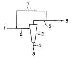
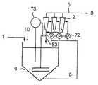
図1は、嫌気性消化汚泥を原汚泥1とし、液体サイクロン2を用いて、汚泥1中のMAP3を濃縮しつつ微粒子の排出管4より排出させ、該MAP3を除去した汚泥を汚泥の排出管(溢流上昇管ともいう)5より溢流させる処理フローである。
FIG. 1 shows that anaerobic digested sludge is
図1に示す液体サイクロン2は、下部構造が逆円錐形となっており、側部に液体サイクロン流入管6(投入管ともいう)、下部に微粒子の排出管4、上部に溢流上昇管5が設けられている。液体サイクロン2では、ポンプの圧送によって、MAP3を含有した消化汚泥1が液体サイクロン流入管6を通して通泥され、液体サイクロン2内部の逆円錐形の壁面を旋回流を起こしながら下降し、消化汚泥より比重の重いMAP3を含む微粒子が、遠心力の働きでより下方の壁面側に集められて濃縮される。濃縮された微粒子は、微粒子排出管4から連続的に或いは間欠的に抜き出される。また、MAP3を含む微粒子が除去された汚泥(処理汚泥)8は、溢流上昇管5より取り出され、排出される。
The
微粒子の排出管4の管径と、溢流上昇管(汚泥排出管)5の管径は変えることができ、両者を変えることで、流量や粒径分布を変化させることができる。
The pipe diameter of the fine
本発明では、液体サイクロン2の汚泥の排出管を流出した汚泥を、処理汚泥の返送管7(返送管A)を経て液体サイクロン流入管6に返送する。返送量は、原汚泥1の投入量に比べ、任意の比率で返送することができるが、液体サイクロンに投入するMAP濃度が所定の濃度以下となるように、返送量を決めることが望ましく、その設定値は、液体サイクロン2の大きさや、汚泥の排出管径、微粒子の排出管径によって変えるのがよい。特に、微粒子の排出管の断面積あたりの微粒子の排出速度(kg/mm2/hr)は、液体サイクロンが閉塞するか否かを決める極めて重要な因子であり、ある排出速度以上となると閉塞する。2インチサイクロンの場合は、投入圧やサイクロン形状などによっても異なるが概ね10kg/mm2/hr以上で閉塞するので、5kg/mm2/hr以下、好ましくは2kg/mm2/hr以下となるように、サイクロン流入管中のMAPを含む微粒子の濃度を低下させる。
In the present invention, the sludge that has flowed out of the sludge discharge pipe of the
処理汚泥の返送量は、後述の実施例3で示すように、原汚泥1の投入量に比べて0.1倍以上とするのが好ましく、上限は特に設けないが、好ましくは経済的な循環比を考慮して50倍以下とするのが好ましい。
The return amount of the treated sludge is preferably 0.1 times or more as compared with the input amount of the
汚泥の流出管5から流出した汚泥は、一時的に貯留槽(図示省略)に貯留した後、サイクロンの流入管6に返送しても良いし、貯留槽を経由せず返送してもよい。残りの汚泥は処理汚泥8として回収され、適宜脱水工程などにかけられる。
The sludge flowing out from the
このようにして、液体サイクロンの溢流上昇管より流出した処理汚泥を、サイクロン流入管に返送することで、サイクロン流入管中のMAPを含む微粒子の濃度が低下して、サイクロンの閉塞を防止することができる。また、サイクロン流入管中のMAPを含む微粒子の濃度が低下することで、溢流上昇管より排出される汚泥中のMAP濃度も低下することで、MAP回収率が上昇する。 In this way, the treated sludge that has flowed out of the liquid cyclone overflow ascending pipe is returned to the cyclone inflow pipe, so that the concentration of fine particles containing MAP in the cyclone inflow pipe is reduced, and the cyclone is blocked. be able to. Moreover, the concentration of fine particles containing MAP in the cyclone inflow pipe decreases, and the MAP concentration in the sludge discharged from the overflow riser pipe also decreases, thereby increasing the MAP recovery rate.
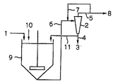
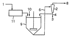
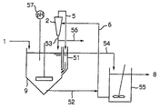
図2は、本発明の他の形態であり、晶析リアクタ9と液体サイクロン2からなる処理フローからなるものである。
FIG. 2 shows another embodiment of the present invention, which comprises a processing flow comprising a
晶析リアクタ9では、嫌気性消化槽から抜き出した消化汚泥や消化脱離液1に対し、晶析用の薬品としてマグネシウム化合物10を添加することで、液中に溶解しているPO4−Pと反応させて、MAPを析出させる。このとき、曝気処理や減圧処理などを併用すると、脱炭酸してpHが上昇し、より効率的にMAPを析出させることができる。無論、水酸化ナトリウム、水酸化マグネシウム、酸化マグネシウム等の薬品を添加してpHを上昇させてもよい。添加するマグネシウム化合物10としては、塩化マグネシウムのほか、水酸化マグネシウム、酸化マグネシウム、海水等を使用することができる。マグネシウムの添加量は、消化汚泥中の溶解性のオルトリン酸濃度に対し、モル比で0.1〜10、好ましくは0.5〜3.0、より好ましくは0.8〜1.2がよい。反応におけるpHは、7.0〜11.0、好ましくは7.5〜8.5がよい。
In the
更に、効率的にMAPを生成させるためには、晶析リアクタ9に種晶を添加しておくと好ましい。種晶としては、晶析リアクタ9で析出したMAP、或いは別のリアクタで析出したMAPを用いることができ、更には、消化槽で自然発生的に析出したMAPを用いることもできる。
Further, in order to efficiently generate MAP, it is preferable to add seed crystals to the
また、液体サイクロン2で回収したMAP3を含む微粒子等を用いることもできる。この場合、液体サイクロン2で分離回収した微粒子を、返送管11(返送管B)によって晶析リアクタ9に返送することができる。更に、分離工程途中の分離水や、流出水等にMAPが含まれている場合は、これらを用いてもよい。
In addition, fine particles containing MAP3 collected by the
このほか、リン鉱石やドロマイト、骨炭、活性炭、けい砂、珪酸カルシウム等の粉末或いは粒状物を用いることができる。種晶の粒径は任意でよいが、好ましくは0.05〜3.0mm、より好ましくは0.1〜0.5mmがよい。種晶の表面で新たなMAPを析出させることで、後段の液体サイクロン2での消化汚泥とMAP3の分離が良好になる。種晶の表面で析出させるには、種晶の充填量がきわめて重要である。充填量は、リンの投入量と、種晶粒径を考慮し、種晶の表面積当たりのリン投入量(以下リン表面積負荷という)が、100g−P/m2/d以下、好ましくは30g−P/m2/d以下、より好ましくは10g−P/m2/d以下とするのがよい。即ち、同一の粒径に対しては、リアクタ9内に高濃度のMAPを維持すると、リアクタ容積を小さくすることが可能となり、イニシャルコストの低減を図ることができる。
In addition, powders or granular materials such as phosphate ore, dolomite, bone charcoal, activated carbon, silica sand, and calcium silicate can be used. The particle size of the seed crystal may be arbitrary, but is preferably 0.05 to 3.0 mm, more preferably 0.1 to 0.5 mm. By separating new MAP on the surface of the seed crystal, the separation of digested sludge and MAP3 in the
ここで、晶析工程におけるリアクタ9の形式は、とくに限定されることなく、機械式の撹拌装置を備えた完全混合型のリアクタ、ポンプを用いた噴流式撹拌リアクタ、種晶を高密度に充填した流動層型のリアクタ、ドラフトチューブを備えた内部循環型のリアクタ、外部循環型のリアクタ等を用いることができる。
Here, the type of the
晶析工程で析出させたMAPは、晶析リアクタ9の底部から引き抜き、液体サイクロン流入管6によって前述した液体サイクロン2に投入して液体サイクロン2で分離回収する。ここでも、液体サイクロン2の溢流上昇管5から流出した汚泥を、返送管7(返送管A)によって液体サイクロン流入管6に返送する。このように、晶析工程で高濃度に維持したMAP濃度を、処理汚泥8で希釈することで、サイクロン2の閉塞を防止することができ、高いMAP回収率で安定した処理性能を得ることが可能となる。なお、図2において、10はMg化合物である。MAPを生成させるMg化合物は、晶析リアクタ内に添加するので、MAP生成は晶析リアクタ9で起こる。液体サイクロン2ヘの汚泥の投入は連続的に行っても、間欠的に行っても良い。
The MAP deposited in the crystallization step is pulled out from the bottom of the
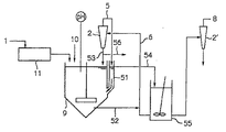
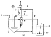
図3は、本発明の更に別の形態の一例のフロー図であり、汚泥1を液体サイクロン2に投入する前段で、し渣除去装置11を設けている。従来は、し渣の分離工程がないために、後段の液体サイクロン2で、し渣等による閉塞の問題があった。そのため、長期安定処理が課題としてあった。本発明では、し渣を除去することで、液体サイクロンを用いたMAP粒子の分離の安定性を飛躍的に向上させることができる。更に、し渣を予め分離することで、純度の高いMAPを得ることができる。また、し渣除去装置11は、液体サイクロン流入管6の途中に取り付けることもできる。
FIG. 3 is a flowchart of an example of still another embodiment of the present invention, in which a screen
除去したし渣は、系外に排出してもよいし、処理汚泥8の脱水工程に投入してもよい。後者の場合、脱水性能が向上するので好ましい。
The removed residue may be discharged out of the system or may be put into the dewatering process of the treated
晶析工程とし渣の分離工程の順序は問わない。晶析工程の後にし渣の分離工程でもよいし、し渣の分離工程の後に晶析工程でもよい。 The order of the crystallization step and the residue separation step is not limited. After the crystallization step, a residue separation step may be performed, or after the residue separation step, a crystallization step may be performed.
し渣の分離方法としては、遠心沈降機、重力分離を利用した沈降分離槽などがあり、粒子径の違いを利用した微粒子の分離方法としては、振動ふるい、ドラムスクリン、ろ過層や分級層型分離層などがある。 There are centrifugal sedimentators, sedimentation tanks using gravity separation, etc. as the separation method of the residue, and the separation methods of fine particles using the difference in particle diameter include vibrating sieve, drum screen, filtration layer and classification layer type There are separation layers.
本発明の更に他の形態を図4〜図6に示す。 Still another embodiment of the present invention is shown in FIGS.
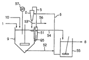
図4は、攪拌装置を備えた晶析リアクタ9と液体サイクロン2と循環水槽55とから構成される処理フローである。
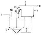
FIG. 4 is a processing flow composed of the
晶析リアクタ9では、粒子と液の混合をよくするため、粒子の良好な流動状態を保つために攪拌を行うことが好ましい。攪拌方式は、原動機付きの機械的な攪拌装置を用いてもよいし、エアを供給することで攪拌をおこなってもよい。
In the
晶析リアクタ9には、原水1の供給管、薬品10の供給管、リアクタと下部が連通している返送管51、リアクタ内の汚泥や粒子を引抜く引抜管52、液体サイクロンの微粒子排出管53が接続されており、返送管51には循環水流出管54が接続されている。原水の汚泥中には、りん酸イオンが100〜600mg/L、アンモニア性窒素が50〜3000mg/L含まれている。薬品10としては、MAPを生成するためのマグネシウム源を供給する。マグネシウム源としては、塩化マグネシウムや水酸化マグネシウム、酸化マグネシウムなどを採用することができる。
The
晶析リアクタ9は、底部平断面の面積が上端平断面の面積よりも小さな構造であることが好ましい。また、上端から下方の所定位置までの平断面が同じ形状で且つ同じ断面積であり、該所定位置から下方はその断面が徐々に縮小するような形状であることが好ましい。例えば、図4に示すように底部が逆円錐形の形状が好ましい。逆円錐形の角度は、水平に対して45°以上、好ましくは60°以上とすることが好ましい。このように角度を設けることで、晶析リアクタ9内で沈降したMAP粒子がリアクタ底部の一点に集中するような構造とすることが好ましい。更に、粒子の引抜管52は沈降した粒子が集中する付近に接続することが好ましい。この効果として、堆積物による閉塞を防止することができる。
The
液体サイクロン2の微粒子排出管53は、サイクロン2で濃縮したMAP粒子をサイクロン2の底部から排出して晶析リアクタ9に返送するものである。液体サイクロン2で濃縮したMAP粒子を晶析リアクタ9に返送することで、リアクタ内のMAP粒子濃度を高めることができ、その結果MAP粒子表面積を大きく維持することが可能となる。晶析反応は粒子の核化現象と成長現象からなるが、粒子表面積が大きいほど、核化現象よりも成長現象が優先されるので固液分離が容易となり好ましい。また、液体サイクロン2の底部或いは微粒子排出管53に、濃縮されたMAP粒子を回収する回収管56を接続することができる。
The fine
図4に示す形態の重要な構成要件は、晶析リアクタ9に返送管51を設置したことにある。返送管51は、液体サイクロン2の溢流上昇管5と、循環水流入管54とに接続されており、さらに晶析リアクタ9と底部で連通している。液体サイクロン2においてMAP粒子が除去された汚泥は溢流上昇管5を通って、全量返送管51に供給される。返送管51はリアクタ9の水面と同じ水位を保っており、返送された汚泥の一部はリアクタ9に返送され、残りは循環水流入管51を通して循環水槽55に供給される。
4 is that the
液体サイクロンへの投入流量は採用するサイクロンの大きさによって概ね決まり、2インチサイクロンで約4m3/hr、4インチサイクロンで約20m3/hrとなる。実際の投入流量が所定流量よりも大きいか又は小さいと処理性能が異なる。従来の晶析リアクタは、返送管51がないので、原水1の供給量と、液体サイクロンアンダー流量(リアクタ底部の微粒子排出管53の流量)と、薬品10の供給量との合計と、引抜管52からの引抜量を一致させることが困難で、リアクタ9における水面の上昇や低下の原因となっていた。そのためレベル計などを設置して水位を制御する必要があった。図4に示す形態では、晶析リアクタ9に返送管51を設置することで、上記の問題を解決することができる。即ち、返送管51をリアクタ9と連通させて液体サイクロン2の溢流上昇管5から排出される汚泥を返送管51を介してリアクタ9に返送すること、また原水供給量と薬品供給量の相当量の汚泥を常時返送管51よりオーバーフローさせることで、リアクタ9の水面を一定に保つことができる。そのためレベル計の設置を省略できるほか、サイクロンへの連続投入が可能となり、また水位が安定することで処理が安定する効果を奏する。
Put flow to the hydrocyclone is determined largely by the size of the cyclone employed, is about 20 m 3 / hr at about 4m 3 / hr, 4
返送管51よりオーバーフローした汚泥は循環水流入管54によって循環水槽55に導かれ、一部がオーバーフローして処理汚泥8として取り出され、残りが液体サイクロン流入管6によって液体サイクロン2に投入される。
The sludge overflowed from the
リアクタ9内のMAP粒子は、引抜管52より所定の流量で引抜き、液体サイクロン流入管6より液体サイクロン2に投入する。ここで重要な構成要件は、引抜管52と液体サイクロンの流入管6を接続することで、引抜管52内の粒子濃度を循環水槽55からの循環水(汚泥)で希釈した後サイクロンに投入することである。液体サイクロンへ投入するMAP粒子の濃度は、液体サイクロンの処理性能を左右する重要な操作因子であり、処理水の粒子濃度の低下、サイクロンアンダ(サイクロン底部)の閉塞防止のため、濃度が低いほど好ましい。
The MAP particles in the
更に、晶析リアクタ9に供給する原水の供給量をQ1、晶析リアクタ9に供給する薬品の供給量をQ2、液体サイクロン2で分離したMAP結晶を晶析リアクタ9に返送する返送量をQ3、晶析リアクタ9の引抜管52から引き抜くMAP結晶粒子の引抜量をQ4とした場合、これらの関係を、
Q1+Q2+Q3<Q4
に保つことが好ましい。この関係を保つことで、返送管51を通る返送水量Q5の流れ方向を、晶析リアクタ9に向かう方向に維持することができ、晶析リアクタ9内のMAP粒子が循環水流出管を通して流出することを防ぐことができる。
Furthermore, the supply amount of raw water supplied to the
Q1 + Q2 + Q3 <Q4
Is preferably maintained. By maintaining this relationship, the flow direction of the return water amount Q5 passing through the
リアクタ内のpHや水温、汚泥濃度が変動する場合は、pH計57や水温計、汚泥濃度計などを設置して、計測値に応じてpH調整剤を添加したり、加温冷却操作や、汚泥の濃度調整をおこなうことが好ましい。
When the pH, water temperature and sludge concentration in the reactor fluctuate, install a
液体サイクロン2は、下部構造が逆円錐形となっている形状が好ましい。液体サイクロン2には、液体サイクロン流入管6、粒子の微粒子排出管53、溢流上昇管(汚泥の排出管)5が接続されている。液体サイクロン2では、ポンプの圧送によってMAP粒子を含有した汚泥がサイクロン流入管6より投入され、逆円錐形の壁面を旋回流を起こしながら下降し、汚泥より比重の重いMAPを含む粒子が、遠心力の働きでより下方の壁面側に集められて濃縮される。濃縮された微粒子は、微粒子排出管53によって連続的に或いは間欠的にリアクタに返送する。また、適宜回収管56によって回収してもよい。
The
液体サイクロン流入管6内の粒子の濃度は、液体サイクロン2の処理性能を左右する重要な操作因子であり、処理水の粒子濃度の低下、サイクロンアンダの閉塞防止のため、濃度が低い程好ましい。どの程度まで、粒子濃度を低下させればよいかは、サイクロンの濃縮性能にもよって異なるが、概ね数十g/Lが好ましい。
The concentration of particles in the
溢流上昇管5からは、前述したようにMAP粒子が除去された汚泥が流出する。溢流上昇管5は晶析リアクタ9の返送管51に接続されており、MAP微粒子が除去された汚泥は全量返送管51に供給される。
From the
液体サイクロン2において、微粒子排出管の管径と、汚泥の排出管の管径は変えることができ、両者を変えることで、流量や粒径分布を変化させることができる。
In the
循環水槽55には、晶析リアクタ9の返送管51に接続した循環水流入管54と、液体サイクロンへの流入管6、及び処理水(汚泥)8の流出管が接続されている。循環水流入管54を通して流入した汚泥の一部8が、処理水流出管にオーバーフローする。循環水槽55は、循環水(処理水と同じ性状)を一時的に貯留する槽であり、任意の大きさにすることができる。無論、攪拌装置を設置して均一になるように混合してもよい。
The circulating
なお、汚泥1の供給管及び/又は晶析リアクタ9の底部に接続した引抜管52にし渣除去装置を配置することができる。し渣を除去することで、液体サイクロン2を用いたMAP粒子の分離の安定性を飛躍的に向上させることができる。更に、し渣を予め分離することで、純度の高いMAPを得ることができる。
In addition, a residue removing device can be disposed in the
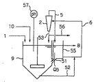
図5に示す例は、返送管51の上部に循環水槽55を直接設置した例である。このようにすることで、図4の形態と比較して循環水流入管54を省略することができる。
The example shown in FIG. 5 is an example in which a circulating
なお、図6に示すように、晶析リアクタ9の逆円錐形部分の更に底部を円柱状などの形状にして、引抜管52を円柱状の部分に接続してもよい。
As shown in FIG. 6, the bottom of the inverted conical portion of the
図4〜図6に示すように、液体サイクロン2で濃縮したMAP粒子を回収する粒子の回収管56を液体サイクロン2の底部或いは微粒子排出管53に接続することができる。通常、晶析反応の進行と共に晶析リアクタ9内のMAP粒子濃度が増加していくので、適時MAP粒子を液体サイクロン2から抜出すことで、晶析リアクタ9内のMAP粒子濃度を一定濃度に維持することができる。液体サイクロン2で濃縮されたMAP粒子は、微粒子排出管53を通して晶析リアクタ9に返送されるので、回収管56を微粒子排出管53に接続して、濃縮MAP粒子の一部を回収管56を通して外部に抜出すことができる。濃縮MAP粒子は、例えばバルブの切り替えによって排出するとよい。バルブの切り替えは、定時的なタイマー設定による切り替えでも良いし、晶析リアクタ9内の粒子濃度を検出して、検出値に応じて切り替えても良い。
As shown in FIGS. 4 to 6, a
回収したMAP粒子は洗浄したり、水切りしたり、乾燥するなどして、粒子の再利用用途に応じた処理を行うことができる。 The collected MAP particles can be processed according to the reuse application of the particles by washing, draining, or drying.
また、液体サイクロンを洗浄する洗浄水を供給する洗浄管(図示せず)を微粒子排出管53或いは回収管56に接続することができる。通常、液体サイクロン2のアンダ(底部)が閉塞しないように、予め粗大粒子を除去したり、液体サイクロン2へ投入する粒子濃度を低下させるなどするが、それでもなお、場合によっては閉塞することがある。この場合、洗浄水をサイクロンアンダ(底部)から上向流で通水し、粒子をサイクロン本体側へ押し出すようにするとよい。洗浄水を供給する場合、微粒子排出管と回収管はバルブなどで閉じておくとよい。
In addition, a cleaning pipe (not shown) for supplying cleaning water for cleaning the liquid cyclone can be connected to the fine
本発明の更に他の形態では、液体サイクロンを複数台並列に接続することで、、晶析リアクタを小型化し、液体サイクロンが閉塞することなく、晶析リアクタ内のMAP粒子濃度を高濃度に維持して安定した処理を可能とする処理システムが提供される。かかる形態の例を図7〜図10に示す。 In yet another embodiment of the present invention, a plurality of liquid cyclones are connected in parallel to reduce the size of the crystallization reactor and maintain the MAP particle concentration in the crystallization reactor at a high level without blocking the liquid cyclone. Thus, a processing system that enables stable processing is provided. Examples of such forms are shown in FIGS.
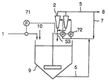
図7は、晶析リアクタ9を用いて原汚泥1中に溶解しているリンを結晶化すると共に、液体サイクロン2を用いて、汚泥中のMAPを濃縮しつつ微粒子の排出管53より排出させ、MAPを除去した汚泥8を汚泥の排出管(溢流上昇管)より溢流させる処理フローである。
FIG. 7 shows that
原汚泥1は、し渣除去装置(或いは夾雑物除去装置ともいう)によって予めし渣等の夾雑物を除去することが好ましい。し渣除去装置としては、遠心沈降機、重力分離を利用した沈降分離槽などがあり、粒子径の違いを利用した微粒子の分離方法としては、振動ふるい、バースクリーン、ドラムスクリン、ろ過層や分級層型分離層などや、それらの装置原理を組み合わせた装置がある。晶析リアクタ9及び/又は液体サイクロン2の前段に、し渣除去装置を設置することで、晶析リアクタ9における攪拌装置への夾雑物の絡まり、液体サイクロン2における閉塞を防止することができ、処理の安定化と、清掃メンテナンス頻度を減少させることができる。更に、し渣を予め分離することで、純度の高いMAPを得ることができる。なお、し渣除去装置は、晶析リアクタ9の底部に接続した液体サイクロン流入管6に配置してもよい。
The
晶析リアクタ9には、原汚泥1の供給管、マグネシウム10の供給管、液体サイクロン2の微粒子排出管53、汚泥排出管(溢流上昇管)5が接続され、場合によっては、更にpH計やpH調整剤の供給管を設置する。リアクタの形式は、とくに限定されることなく、機械式の攪拌装置を備えた完全混合型のリアクタ、ポンプを用いて噴流式攪拌リアクタ、種晶を高密度に充填した流動層型のリアクタ、ドラフトチューブを備えた内部循環型のリアクタ、外部循環型のリアクタ、等を用いることができる。
The
汚泥を対象とする場合は、強いせん断力を与えることが可能な機械的な攪拌装置を備えた完全混合型のリアクタを用いるのがよい。 When sludge is targeted, it is preferable to use a fully mixed reactor equipped with a mechanical stirring device capable of applying a strong shearing force.
晶析リアクタ9では、汚泥や、汚泥の濃縮又は脱水処理による分離水1に対し、マグネシウム化合物10を添加することで、MAPを析出させる。このとき、曝気処理や減圧処理などを併用すると、脱炭酸してpHが上昇し、より効率的にMAPを析出させることができる。無論、水酸化ナトリウム、水酸化マグネシウム、酸化マグネシウム等の薬品を添加してpHを上昇させてもよい。添加するマグネシウム化合物としては、塩化マグネシウムのほか、水酸化マグネシウム、酸化マグネシウム、海水等を使用することができる。マグネシウムの添加量は、消化汚泥中の溶解性のオルトリン酸濃度に対し、モル比で0.1〜10、好ましくは0.5〜3.0、もっと好ましくは0.8〜1.2がよい。反応におけるpHは、7.0〜11.0、好ましくは7.5〜8.5がよい。
In the
更に、効率的にMAPを生成させるために、晶析リアクタ9に種晶を添加しておくとよい。種晶は、消化槽で自然発生的に析出したMAPや、晶析リアクタ9で析出したMAP、液体サイクロン2で濃縮したMAP、別の晶析リアクターで析出したMAPなどを用いることができる。
Further, seed crystals may be added to the
このほか、リン鉱石やドロマイト、骨炭、活性炭、けい砂、珪酸カルシウム等の粉末或いは粒状物を用いることができる。種晶の粒径は任意でよいが、好ましくは0.05〜3.0mm、もっと好ましくは0.1〜0.5mmがよい。種晶の表面で新たなMAPを析出させることで、後段の分離工程での消化汚泥とMAPの分離が良好になる。種晶の表面で析出させるには、種晶の充填量がきわめて重要である。 In addition, powders or granular materials such as phosphate ore, dolomite, bone charcoal, activated carbon, silica sand and calcium silicate can be used. The grain size of the seed crystal may be arbitrary, but is preferably 0.05 to 3.0 mm, more preferably 0.1 to 0.5 mm. By depositing new MAP on the surface of the seed crystal, the separation of digested sludge and MAP in the subsequent separation step is improved. In order to precipitate on the surface of the seed crystal, the filling amount of the seed crystal is very important.
図11に、晶析リアクタ内のMAP量とリン回収率の関係を示した。図11より、MAP充填量が多いほど回収率が増加する傾向があり、リアクタ内に充填するMAP量は少なくとも10g/L以上とすることで、30%以上のリンを回収することが可能である。 FIG. 11 shows the relationship between the amount of MAP in the crystallization reactor and the phosphorus recovery rate. From FIG. 11, the recovery rate tends to increase as the MAP filling amount increases, and it is possible to recover 30% or more of phosphorus by setting the amount of MAP charged in the reactor to at least 10 g / L or more. .
また、種晶の表面積当たりのリン投入量(以下リン表面積負荷という)は、100g−P/m2/d以下、好ましくは30g−P/m2/d以下、もっと好ましくは10g−P/m2/d以下とするのがよい。 The amount of phosphorus input per surface area of the seed crystal (hereinafter referred to as phosphorus surface area load) is 100 g-P / m 2 / d or less, preferably 30 g-P / m 2 / d or less, more preferably 10 g-P / m. 2 / d or less is preferable.
晶析リアクタ内のMAP濃度は、原汚泥の供給量とそれに含有されているMAP濃度、液体サイクロンで濃縮し晶析リアクタに返送されるMAP量と濃度、及びリアクタ内での晶析量できまる。前述のように、リアクタ内のMAP濃度を高めて結晶表面積を大きくすることが重要であるが、原汚泥中のMAP濃度は、液体サイクロンで濃縮したMAP濃度に比べ、1/10〜1/500程度なので、液体サイクロンで濃縮したMAP濃度は、原汚泥によって希釈される。その結果、原汚泥量が多いほど、リアクタ内のMAP濃度を高濃度に維持することが困難であった。 The MAP concentration in the crystallization reactor is determined by the supply amount of raw sludge, the MAP concentration contained in it, the MAP amount and concentration that are concentrated in the hydrocyclone and returned to the crystallization reactor, and the amount of crystallization in the reactor. . As described above, it is important to increase the MAP concentration in the reactor to increase the crystal surface area. However, the MAP concentration in the raw sludge is 1/10 to 1/500 compared to the MAP concentration concentrated with the hydrocyclone. As such, the MAP concentration concentrated in the hydrocyclone is diluted by the raw sludge. As a result, it was difficult to maintain the MAP concentration in the reactor at a high concentration as the amount of raw sludge increased.
そこで、図7〜図10に示す形態では、液体サイクロン2を複数台並列に設置し、各液体サイクロンは独立した制御が可能とする。また、各液体サイクロン2で濃縮したMAPは、全量または一部を微粒子排出管53で晶析リアクタ9に返送する。このような構成を採用することにより、晶析リアクタ9内のMAP濃度を所望の濃度に維持することが可能となるばかりか、液体サイクロン2で濃縮されたMAPの返送量が多くなることから、晶析リアクタ9内のMAP濃度を高濃度に維持することが可能となる。その結果、晶析リアクタ9の小型化に大きく貢献する。
7 to 10, a plurality of
液体サイクロン2の設置台数は2台以上の任意とすることができる。液体サイクロンの濃縮流量と濃縮MAP濃度及び、所望の晶析リアクタ内MAP濃度を考慮して決めることができる。 Two or more hydrocyclones 2 can be installed arbitrarily. It can be determined in consideration of the concentration flow rate and concentration MAP concentration of the hydrocyclone and the desired MAP concentration in the crystallization reactor.
また、図7〜図10に示す形態においても、上述の図4等で示されるように液体サイクロン2の底部又は微粒子排出管53に回収管56を接続して、液体サイクロンで濃縮したMAPの一部を抜出すことで、リアクタ内のMAP濃度を調整することができる。濃縮MAP粒子は、間欠的に抜出しても、連続的に抜出してもよく、特定のサイクロンから抜出しても、各サイクロンから順番に抜出してもよく、或いは全サイクロンから同時に抜出してもよい。抜出したMAPは、肥料や無機薬品、化学原料等として有効利用することができる。
Also, in the forms shown in FIGS. 7 to 10, as shown in FIG. 4 and the like, a
なお、液体サイクロンの溢流上昇管5より流出した微粒子を回収した後の汚泥8の一部をサイクロンの流入管6に返送してもよい。この場合、中継槽を経由すると良い
液体サイクロンを複数台並列に設置した場合、例えば、図8に示すように、液体サイクロンの稼働台数を、原水流量に応じて制御することができる。具体的には、原汚泥1の供給管に流量計71を設置して晶析リアクタ9への原汚泥の流入量をモニタリングして、予め設定された流量範囲と液体サイクロン2の稼働台数の関係から、各液体サイクロン2の流入部に設置されたポンプの稼動台数を決めることにより液体サイクロン2の稼働台数を決定することができる。このようにすることで、原汚泥の流入量の変動があった場合でも、晶析リアクタ9内を所望のMAP濃度に維持することが可能となる。
A part of the
また、図9に示すように液体サイクロン2の稼働台数を、晶析リアクタ内のMAP濃度に応じて制御することができる。晶析リアクタ9内のMAP濃度の測定は、透過光散乱光方式、レーザー光拡散方式、超音波式、マイクロ波式、近赤外光式などの濃度計73を用いて行うことができる。なお、MAP濃度は有機物濃度と合わせて測定される場合もあるが、晶析リアクタ9内の有機物濃度に変動が少ないことを利用し、検量線を作成してMAP濃度を算出することもできる。
Further, as shown in FIG. 9, the number of operating
更に、図10に示すように、晶析リアクタ及び液体サイクロンで処理した汚泥又は分離水、即ち液体サイクロン2の溢流上昇管5から流出する汚泥又は分離水8のリン濃度及びpHをリン濃度計74及びpH計75でモニタリングして、その測定データに基づいて過飽和度比を演算すると共に、過飽和度比に応じてマグネシウムの添加量及び液体サイクロンの稼動台数を制御することができる。
Further, as shown in FIG. 10, the phosphorus concentration and pH of the sludge or separated water treated with the crystallization reactor and the liquid cyclone, that is, the sludge or separated
PHとリン濃度の測定は任意の分析機器を用いることができ、連続的にモニタリングしても、一定期間ごとにモニタリングしても良い。リンは、溶解性のリンのみならず、汚泥や粒子を溶解させたトータルリンを測定することが望ましい。 Arbitrary analytical instruments can be used for measurement of PH and phosphorus concentrations, and monitoring may be performed continuously or at regular intervals. As for phosphorus, it is desirable to measure not only soluble phosphorus but also total phosphorus in which sludge and particles are dissolved.
モニタリングによって得られたpH及びりん濃度を用いて演算装置で過飽和度比を演算する。演算装置としては、パーソナルコンピュータなどが代表的であり、入力装置や表示装置等も含む。 The supersaturation ratio is calculated by an arithmetic unit using the pH and phosphorus concentration obtained by monitoring. The computing device is typically a personal computer and includes an input device and a display device.
以下、過飽和度比について説明する。過飽和度比は以下のようにして演算される。 Hereinafter, the supersaturation ratio will be described. The supersaturation ratio is calculated as follows.
過飽和度比=[Mg2+][NH3 +][PO4 3-]/SP・・・(1)
ここで、SPはMAPの溶解度積を示し、10-12.6(一般水質化学;共立出版株式会社)である。[Mg2+]、[NH3 +]は各イオンのモル濃度を示し、pHによって濃度が変化するので、過飽和度比を演算する未知数は4つとなる。他の過飽和度の表し方としては、
過飽和度=([Mg2+][NH3 +][PO4 3-])(1/3)/SP(1/3)・・・(2)
や、
過飽和度=[Mg2+][NH3 +][PO4 3-]―SP・・・(3)
などがあり、いずれも、溶解度積からのずれを指標としている。ここでは式(1)の過飽和度比を指標として演算を行う。
Supersaturation ratio = [Mg 2+ ] [NH 3 + ] [PO 4 3− ] / SP (1)
Here, SP indicates the solubility product of MAP and is 10 −12.6 (general water chemistry; Kyoritsu Shuppan Co., Ltd.). [Mg 2+ ] and [NH 3 + ] indicate the molar concentration of each ion, and since the concentration changes depending on pH, there are four unknowns for calculating the supersaturation ratio. As another way of expressing the degree of supersaturation,
Supersaturation = ([Mg 2+ ] [NH 3 + ] [PO 4 3− ]) (1/3) / SP (1/3) (2)
Or
Supersaturation = [Mg 2+ ] [NH 3 + ] [PO 4 3− ] −SP (3)
In all cases, the deviation from the solubility product is used as an index. Here, the calculation is performed using the supersaturation ratio in Expression (1) as an index.
式(1)で、過飽和度比が1の場合は、汚泥又は液中が平衡状態にあることを示し、局所的に結晶化と溶解が繰り返されているとしても、全体的としてみれば、結晶化は進まない状態である。過飽和度比が1以上の場合は過飽和状態を示し、イオン積以上の濃度分が結晶化して、MAPスケールが生成する領域である。MAPスケールは、平衡状態となるまで生成し、過飽和度比が高ければ高いほどMAPスケール量が多くなる。過飽和度比が1以下の場合は、未飽和状態を示し、MAPスケールは生成しない領域である。 In the formula (1), when the supersaturation ratio is 1, it indicates that the sludge or liquid is in an equilibrium state, and even if crystallization and dissolution are repeated locally, There is no progress. When the supersaturation ratio is 1 or more, it indicates a supersaturated state, and a MAP scale is generated by crystallization of a concentration higher than the ion product. The MAP scale is generated until the equilibrium state is reached, and the higher the supersaturation ratio, the larger the MAP scale amount. When the supersaturation ratio is 1 or less, it indicates an unsaturated state and is a region where no MAP scale is generated.
下水汚泥の嫌気性消化汚泥中のアンモニウムイオン濃度は、地域性や処理方式によっても異なるが概ね500〜3000mg/Lの間で一定の値となっている。 The ammonium ion concentration in the anaerobic digested sludge of the sewage sludge is a constant value between 500 and 3000 mg / L, although it varies depending on the regional characteristics and the treatment method.
マグネシウム濃度もリン濃度と同様に測定することが望ましいが、薬品としてMg/P=1.0となるように添加しているので、残存するMg濃度は推定でき10〜100mg/Lである。 It is desirable to measure the magnesium concentration in the same manner as the phosphorus concentration, but since the chemical is added so that Mg / P = 1.0, the remaining Mg concentration can be estimated and is 10 to 100 mg / L.
上記のようにして算出した過飽和度比は低いほどMAPのスケールが生成しにくく、30以下、好ましくは10以下、もっと好ましくは5以下とするのがよい。 The lower the supersaturation ratio calculated as described above, the less likely the MAP scale is generated, and it is 30 or less, preferably 10 or less, more preferably 5 or less.
このようにして算出した過飽和度比によって、液体サイクロンの稼動台数を制御することができる。前述したように、晶析リアクタ内のMAP濃度が低くなると、MAPの回収率が低下することから、処理汚泥8の過飽和度比が高くなる。この場合、液体サイクロンの稼動台数を増加させて、晶析リアクタ内のMAP濃度を高めると、処理汚泥中のリン濃度が低くなり、過飽和度比が低下し、スケールの生成を最小限に抑えることができる。
The number of operating hydrocyclones can be controlled by the supersaturation ratio calculated in this way. As described above, when the MAP concentration in the crystallization reactor decreases, the MAP recovery rate decreases, and thus the supersaturation ratio of the treated
また、過飽和度比を算出することで晶析リアクタにおけるマグネシウムの添加量を制御することができる。すなわち、溶解性のリン濃度を測定することで過飽和度比を算出した場合、過飽和度比が高いとリン濃度が高いので、マグネシウムの添加量を増大させてリン濃度を低下させることができる。 Further, the amount of magnesium added in the crystallization reactor can be controlled by calculating the supersaturation ratio. That is, when the supersaturation ratio is calculated by measuring the soluble phosphorus concentration, if the supersaturation ratio is high, the phosphorus concentration is high. Therefore, the amount of magnesium added can be increased to decrease the phosphorus concentration.
なお、図7〜図10においては図示されていないが、図2〜図6の構成のフローにおいて説明したように、液体サイクロン2の溢流上昇管5から流出するMAP粒子が除去された処理汚泥を液体サイクロン2の流入管6に返送してもよいし、また、液体サイクロン2で濃縮された粒子スラリーを適宜取り出して回収してもよい。
Although not shown in FIGS. 7 to 10, the treated sludge from which the MAP particles flowing out from the
このような複数台の液体サイクロンの設置及びその運転制御は、例えば、図2〜図6に示されるような構成のフロー、或いは後述する図12〜17或いは図18に示す構成のフローにおいても採用することができる。 Such installation and operation control of a plurality of hydrocyclones are also employed in, for example, the flow shown in FIGS. 2 to 6 or the flow shown in FIGS. 12 to 17 or 18 described later. can do.
更に本発明の他の態様では、有機性廃棄物を嫌気性消化して発生した消化汚泥を処理するにあたって、消化汚泥を脱炭酸する工程又は消化汚泥からMAPを析出させる晶析工程、消化汚泥中のし渣を除去する工程、及び脱炭酸工程又は晶析工程とし渣除去工程を経た消化汚泥からMAPを含む結晶を分離又は濃縮する工程を備えた処理プロセスが提供される。
即ち、本発明の他の形態は以下の通りである。
Furthermore, in another aspect of the present invention, in treating digested sludge generated by anaerobic digestion of organic waste, a step of decarboxylating the digested sludge or a crystallization step of depositing MAP from the digested sludge, There is provided a treatment process comprising a step of removing a residue and a step of separating or concentrating crystals containing MAP from digested sludge that has been subjected to a residue removal step as a decarboxylation step or a crystallization step.
That is, another embodiment of the present invention is as follows.
14.有機性廃棄物を嫌気性消化して発生した消化汚泥を処理する装置において、
前記消化汚泥を脱炭酸する装置と、
前記消化汚泥中のし渣を除去する除去装置とを備え、
前記脱炭酸する装置と除去装置とを経た前記消化汚泥からリン酸マグネシウムアンモニウムを含む結晶を分離又は濃縮する装置を備える
ことを特徴とする消化汚泥の処理装置。
14 In the equipment to treat digested sludge generated by anaerobic digestion of organic waste,
An apparatus for decarboxylating the digested sludge;
A removal device for removing residue in the digested sludge,
An apparatus for treating digested sludge, comprising a device for separating or concentrating crystals containing magnesium ammonium phosphate from the digested sludge that has passed through the decarbonation device and the removal device.
15.有機性廃棄物を嫌気性消化して発生した消化汚泥を処理する装置において、
前記消化汚泥からリン酸マグネシウムアンモニウムを析出させる晶析リアクタと、
前記消化汚泥中のし渣を除去する除去装置とを備え、
前記晶析リアクタとし渣除去装置とを経た前記消化汚泥からリン酸マグネシウムアンモニウムを含む結晶を分離又は濃縮する装置を備える
ことを特徴とする消化汚泥の処理装置。
15. In the equipment to treat digested sludge generated by anaerobic digestion of organic waste,
A crystallization reactor for precipitating magnesium ammonium phosphate from the digested sludge;
A removal device for removing residue in the digested sludge,
An apparatus for treating digested sludge, comprising an apparatus for separating or concentrating crystals containing magnesium ammonium phosphate from the digested sludge that has passed through the crystallization reactor and a residue removing device.
16.前記し渣除去装置が、穴径が異なる2種類以上のふるい体を装備した湿式振動ふるいであることを特徴とする上記第14項又は第15項に記載の消化汚泥の処理装置。 16. 16. The digested sludge treatment apparatus as described in 14 or 15 above, wherein the residue removing device is a wet vibration sieve equipped with two or more types of sieve bodies having different hole diameters.
17.分離されたリン酸マグネシウムアンモニウムを含む結晶を洗浄する洗浄装置を更に具備することを特徴とする上記第14項乃至16項のいずれかに記載の消化汚泥の処理装置。 17. 17. The digested sludge treatment apparatus according to any one of items 14 to 16, further comprising a washing apparatus for washing the separated crystal containing magnesium ammonium phosphate.
更に、本発明の他の一面では、有機性廃棄物を嫌気性消化して発生した消化汚泥を配管輸送する際の配管内のスケールを防止する方法において、前記消化汚泥を、脱炭酸する工程及びし渣を除去する工程で処理した後、該脱炭酸及びし渣を除去した消化汚泥からMAPを含む微粒子を分離し、該微粒子が除去された消化汚泥を配管輸送することを特徴とする配管内のスケールの防止方法が提供される。 Furthermore, in another aspect of the present invention, in the method for preventing scale in the piping when piping the digested sludge generated by anaerobic digestion of organic waste, the step of decarboxylating the digested sludge and After processing in the step of removing debris, separating fine particles containing MAP from the digested sludge from which decarbonation and debris have been removed, and transporting the digested sludge from which the fine particles have been removed by piping A method for preventing the scale is provided.
本発明方法において、微粒子が除去された消化汚泥は、pHを低下させる処理及び/又はマグネシウムイオン、リン酸イオン、アンモニウムイオンの内の少なくとも1つの濃度を低下させる処理を行い、その後、該消化汚泥を配管輸送するのがよく、前記嫌気性消化は、有機性廃棄物からリン酸イオンを吐き出させる吐き出し工程と、該吐き出し処理をした有機性廃棄物を濃縮する濃縮工程で処理した後に行うことができ、また、配管輸送する消化汚泥は、マグネシウムイオン濃度が20mg/L以下、好ましくは5mg/L以下であるのがよい。 In the method of the present invention, the digested sludge from which fine particles have been removed is subjected to a treatment for lowering pH and / or a treatment for reducing the concentration of at least one of magnesium ion, phosphate ion and ammonium ion, and then the digested sludge. The anaerobic digestion is carried out after the treatment in the discharge step of discharging phosphate ions from the organic waste and the concentration step of concentrating the organic waste subjected to the discharge treatment. The digested sludge that can be transported by piping has a magnesium ion concentration of 20 mg / L or less, preferably 5 mg / L or less.
また、本発明の他の一面では、有機性廃棄物を嫌気性消化槽で処理して発生した消化汚泥を配管輸送する際の配管内のスケールを防止する装置において、前記消化汚泥を脱炭酸する装置と消化汚泥からし渣を除去する装置とを備え、該脱炭酸する装置とし渣を除去する装置とを経た消化汚泥から、MAPを含む微粒子を分離する装置を備えることを特徴とする配管内のスケールの防止装置が提供される。 In another aspect of the present invention, the digested sludge is decarboxylated in an apparatus for preventing scale in the piping when piping the digested sludge generated by treating organic waste in an anaerobic digester. An apparatus and a device for removing residue from digested sludge, and a device for separating fine particles containing MAP from digested sludge that has passed through the decarbonation device and the device for removing residue A scale prevention device is provided.
本発明装置において、微粒子を分離する装置の後段には、微粒子が除去された消化汚泥のpHを低下させる薬品添加装置及び/又はマグネシウムイオン、リン酸イオン、アンモニウムイオンの内の少なくとも1つの濃度を低下させる薬品添加装置を備えるのがよく、また、前記嫌気性消化槽の前段には、有機性廃棄物からリン酸イオンを吐き出させる吐き出し手段と、該吐き出し処理をした有機性廃棄物を濃縮する濃縮装置を設置することができる。 In the apparatus of the present invention, a chemical addition apparatus that lowers the pH of the digested sludge from which fine particles have been removed and / or a concentration of at least one of magnesium ions, phosphate ions, and ammonium ions is provided downstream of the apparatus for separating the fine particles. It is preferable to provide a chemical addition device for lowering, and in the front stage of the anaerobic digestion tank, there is a discharge means for discharging phosphate ions from the organic waste, and the organic waste subjected to the discharge treatment is concentrated. A concentrator can be installed.
更に本発明の他の一面では、有機性廃棄物を嫌気性消化して発生した消化汚泥を処理する方法において、該消化汚泥を、マグネシウム化合物を添加することでMAPを析出させる晶析工程と、該消化汚泥からし渣を除去するし渣の除去工程とで処理し、前記晶析工程とし渣の除去工程を経た該消化汚泥からMAPを含む微粒子を分離工程で回収し、該微粒子が除去された消化汚泥を脱水工程で脱水することを特徴とする消化汚泥の処理方法が提供される。本発明方法において、分離工程で回収したMAPを含む微粒子、又は、該分離工程内のMAPを含む流出水の一部又は全量を、前記晶析工程に返送することができ、また、前記し渣の除去工程で除去したし渣の一部又は全量を、前記脱水工程に供給することができ、さらに、前記微粒子が除去された消化汚泥は、pHを低下させる処理及び/又はマグネシウムイオン、リン酸イオン、アンモニウムイオンの内の少なくとも1つの濃度を低下させる処理を行った後に、該消化汚泥を前記脱水工程に移送するのがよい。 Furthermore, in another aspect of the present invention, in a method of treating digested sludge generated by anaerobic digestion of organic waste, the digested sludge is crystallized in which MAP is precipitated by adding a magnesium compound; After removing the residue from the digested sludge and removing the residue, the fine particles containing MAP are recovered from the digested sludge that has been subjected to the crystallization step and the residue removing step in the separation step, and the particles are removed. A digested sludge treatment method is provided, characterized in that the digested sludge is dehydrated in a dehydration step. In the method of the present invention, fine particles containing MAP recovered in the separation step, or a part or all of the effluent water containing MAP in the separation step can be returned to the crystallization step, and the residue Part or all of the residue removed in the removal step can be supplied to the dehydration step, and the digested sludge from which the fine particles have been removed is treated with a process for lowering pH and / or magnesium ions, phosphoric acid. It is preferable to transfer the digested sludge to the dehydration step after performing a treatment for reducing the concentration of at least one of ions and ammonium ions.
更に本発明の他の一面では、有機性廃棄物を嫌気性消化して発生した消化汚泥を処理する装置において、該消化汚泥を処理するMAPを析出させるためのマグネシウム化合物の添加手段を有する晶析装置と、該消化汚泥からし渣を除去するし渣の除去装置とを備え、前記晶析装置とし渣の除去装置とを経た該消化汚泥からMAPを含む微粒子を回収する分離装置と、該微粒子が除去された消化汚泥を脱水する脱水装置とを備えることを特徴とする消化汚泥の処理装置が提供される。本発明装置において、分離装置で回収したMAPを含む微粒子の一部又は全量を、前記晶析装置に返送する返送経路を有し、また、前記し渣の除去装置で除去したし渣の一部又は全量を、前記脱水装置に供給する供給手段を有してもよく、さらに、分離装置の後段には、微粒子が除去された消化汚泥のpHを低下させる薬品添加装置、及び/又はマグネシウムイオン、リン酸イオン、アンモニウムイオンの内の少なくとも1つの濃度を低下させる薬品添加装置を備えることができる。 Furthermore, in another aspect of the present invention, in an apparatus for treating digested sludge generated by anaerobic digestion of organic waste, crystallization having a magnesium compound addition means for precipitating MAP for treating the digested sludge A separation device for collecting fine particles containing MAP from the digested sludge that has passed through the apparatus for removing the residue from the digested sludge and a residue removing device for removing the residue from the digested sludge. A digested sludge treatment apparatus is provided, comprising: a dewatering device for dewatering the digested sludge from which water has been removed. In the apparatus of the present invention, there is a return path for returning a part or all of the fine particles containing MAP recovered by the separator to the crystallizer, and a part of the residue removed by the residue removing device. Alternatively, it may have supply means for supplying the entire amount to the dehydrator, and further, a chemical addition device for lowering the pH of the digested sludge from which fine particles have been removed, and / or magnesium ions, A chemical addition device for reducing the concentration of at least one of phosphate ions and ammonium ions can be provided.
このような構成を採用することにより、消化汚泥を輸送する配管内のMAPスケールを大幅に減少させることができ、及び/又は、消化槽内のリンを効率的に回収することができる。 By employ | adopting such a structure, the MAP scale in the piping which conveys digested sludge can be reduced significantly, and / or the phosphorus in a digestion tank can be collect | recovered efficiently.
以下、図12〜17を参照してかかる態様について説明する。 Hereinafter, this aspect will be described with reference to FIGS.
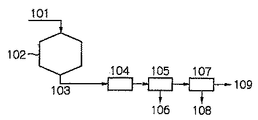
嫌気性消化槽102では、余剰汚泥及び/又は初沈汚泥が投入される。嫌気性消化槽内では、約55℃、或いは、約35℃を保つように加温されている。嫌気性消化槽内で前記汚泥は、酸発酵菌、メタン生成菌の働きにより、メタン、二酸化炭素、硫化水素等のガス、水溶性の窒素、リン等に分解される。発生したメタンガスは、回収することによってエネルギー利用することが可能である。余剰汚泥のみならず、易分解性の生汚泥を投入することで、さらにメタンガスの発生量が増加する。汚泥の分解と共に、リン、マグネシウム、アンモニウムが液側に移行することで、嫌気性消化槽内で自然発生的に生成するMAPが発生する。MAPの析出により、ドラフトチューブや嫌気性消化槽底部、或いは汚泥の排出配管等にスケールトラブルが発生していた。
In the
消化汚泥中のリン、マグネシウム、アンモニウムの比率は、概ねリン:マグネシウム:アンモニウム=100〜500:数〜数十:1000であり、リン、アンモニウムに比べ圧倒的にマグネシウム濃度が低い。消化槽内でMAPの生成は、明らかにマグネシウム濃度が律速となっている。 The ratio of phosphorus, magnesium and ammonium in the digested sludge is generally phosphorus: magnesium: ammonium = 100 to 500: several to several tens: 1000, and the magnesium concentration is overwhelmingly lower than phosphorus and ammonium. The production of MAP in the digester is clearly rate-limited by the magnesium concentration.
消化汚泥には、MAPを含む微粒子が含まれ、pHは7付近、リン濃度100〜500mg/L、マグネシウム数〜数十mg/L、アンモニア500〜4000mg/Lが含まれている。従来、この性状の消化汚泥を配管輸送する際に、管きょ内でMAPスケールが多量に生成し、閉塞等の問題が起こっていた。 Digested sludge contains fine particles containing MAP, pH is around 7, phosphorus concentration is 100 to 500 mg / L, magnesium is several to several tens mg / L, and ammonia is 500 to 4000 mg / L. Conventionally, when the digested sludge having this property is transported by piping, a large amount of MAP scale is generated in the pipe soot and problems such as blockage have occurred.
本発明者等が鋭意研究し、スケールの生成現象を探求したところ、配管内でpHの変動や気相の混入により、脱炭酸が起こり、MAPが生成してスケールとなっていることを突き止めた。言うなれば、前記の消化汚泥には、MAPを生成する潜在能力(以下MAP生成能力という)がまだ残留しているということである。更に悪いことに、消化汚泥中の自然発生的に生成したMAP微粒子が種晶の働きをして、スケールの生成を助長していた。 As a result of diligent research conducted by the present inventors and the search for the phenomenon of scale formation, it was found that decarboxylation occurred due to pH fluctuations and gas phase contamination in the piping, and MAP was generated to form a scale. . In other words, the digested sludge still has the potential to generate MAP (hereinafter referred to as MAP generation capability). To make matters worse, the naturally generated MAP fine particles in the digested sludge acted as seed crystals to promote scale formation.
本発明者らは、上記の残留MAP生成能力に着目し、消化汚泥を管きょに投入する以前に、残留MAP生成能力を低下させる必要があることを見出した。即ち、本発明にあるように、消化汚泥を脱炭酸しpHを上昇させて、予めMAPを生成させること、且つ消化汚泥中に含まれるMAP及び脱炭酸工程で生成したMAPを消化汚泥から分離することで、消化汚泥のMAP生成能力が極めて低下することを見出した。 The present inventors paid attention to the above-mentioned residual MAP generation capability, and found that it is necessary to reduce the residual MAP generation capability before introducing the digested sludge into the pipe. That is, as in the present invention, the digested sludge is decarboxylated to raise the pH to generate MAP in advance, and the MAP contained in the digested sludge and the MAP generated in the decarboxylation step are separated from the digested sludge. As a result, it was found that the MAP generation ability of digested sludge is extremely reduced.
脱炭酸工程104としては、曝気処理や減圧処理がある。曝気処理は、消化汚泥を曝気することで、汚泥中の炭酸ガスが気相中に拡散しpHが上昇し、マグネシウムが残存している分だけMAPが生成する。減圧処理は、特開平7−136406号公報に開示されているような脱気装置(以後、薄膜真空脱気装置と称する)を使用することが望ましい。即ち、真空容器内で回転する有底のふるい体の遠心力により対象液体を加速して対象液体を該真空容器内の壁面に衝突させ、対象液体中の気体を除去する。減圧処理により脱炭酸し、pHが上昇することでMAPが生成する。
The
上記の処理で、液中のマグネシウムイオン濃度が低くなれば、MAPを生成する能力がなく、スケールの発生は抑えられる。例えば、pHを7から8に上昇させると、消化汚泥中のマグネシウムイオン濃度は、概ね1/10〜1/2となる。本発明では、消化汚泥中のマグネシウムイオン濃度は、20mg/L以下、好ましくは5mg/L以下とする。マグネシウムイオン濃度が20mg/L以下であると、管きょ内でのpH変動、例えば、気相混入してpHが上昇したとしても、MAPの過飽和度はほとんど生成せず、MAPの析出を防ぐことができる。 If the magnesium ion concentration in the liquid is lowered by the above treatment, there is no ability to generate MAP, and the generation of scale can be suppressed. For example, when the pH is raised from 7 to 8, the magnesium ion concentration in the digested sludge becomes approximately 1/10 to 1/2. In the present invention, the magnesium ion concentration in the digested sludge is 20 mg / L or less, preferably 5 mg / L or less. When the magnesium ion concentration is 20 mg / L or less, even if the pH in the tube changes, for example, even if the pH rises due to gas phase mixing, almost no supersaturation of MAP is generated and precipitation of MAP is prevented. be able to.
脱炭酸方法として、曝気処理や減圧処理のほか、薬品添加による脱炭酸もある。無論、これらの操作を組み合わせて処理してもよく、順序も任意の順をとることができる。脱炭酸した消化汚泥は、し渣の除去工程105に投入される。従来は、し渣の分離工程が無いために、後段の微粒子の分離工程107で液体サイクロンを用いた場合、し渣等による閉塞の問題があった。そのため、長期安定処理が課題としてあった。本発明では、し渣を除去することで、後段の微粒子の分離工程107、特に液体サイクロンを用いた分離の安定性を飛躍的に向上させることができる。
As a decarboxylation method, there are decarboxylation by chemical addition in addition to aeration treatment and decompression treatment. Of course, these operations may be combined and processed, and the order may be arbitrary. The decarboxylated digested sludge is input to a
除去したし渣106は、系外に排出してもよいし、微粒子の分離工程107の後段で、消化汚泥に混入してもよい。また、脱水工程がある場合は、脱水工程に投入してもよい。この場合、脱水性能が向上するので好ましい。
The removed
なお、脱炭酸工程104とし渣除去工程105の順序は問わない。図12などに示されているように脱炭酸工程104の後にし渣除去工程105を行ってもよいし、し渣除去工程105の後に脱炭酸工程104を行ってもよい。
The order of the
脱炭酸工程104及びし渣の除去工程105の後段では、消化槽内及び脱炭酸工程で析出したMAPを含む微粒子と消化汚泥を分離する。微粒子と消化汚泥の比重差を利用して分離する方法としては、液体サイクロン、遠心沈降機、重力分離を利用した沈降分離槽などがあり、粒子径の違いを利用した微粒子の分離方法としては、振動ふるい、ドラムスクリン、ろ過層や分級層型分離槽などがある。
In the latter stage of the
液体サイクロンは、下部構造が逆円錐形となっており、液体サイクロン流入管、微粒子の排出管、汚泥の排出管からなる。液体サイクロンでは、引き抜きポンプの圧送によって、MAPを含有した消化汚泥が逆円錐形の壁面を旋回流を起こしながら下降し、消化汚泥より比重の重いMAPを含む微粒子が、遠心力の働きでより下方の壁面側に集められて濃縮される。濃縮された微粒子は、連続的に或いは間欠的に抜き出す。 The hydrocyclone has an inverted conical lower structure, and is composed of a hydrocyclone inflow pipe, a particulate discharge pipe, and a sludge discharge pipe. In the hydrocyclone, the digested sludge containing MAP descends while swirling on the inverted conical wall by the pumping pump, and the fine particles containing MAP, which has a heavier specific gravity than the digested sludge, move downward due to the centrifugal force. It is collected on the wall side and concentrated. The concentrated microparticles are extracted continuously or intermittently.
本発明では、MAPを含む微粒子の分離工程107の前段でし渣を分離してあるので、液体サイクロンにおけるし渣等による閉塞の問題は解決されている。上記の脱炭酸工程104、し渣の分離工程105と微粒子の分離工程107を経た消化汚泥は、管きょで汚泥の集約処理施設や他の汚泥処理場、同一敷地内にある汚泥処理施設に輸送される。前記工程により、消化汚泥は、消化汚泥中のマグネシウムイオン濃度が極端に低下しており、且つ消化汚泥中のMAP微粒子が除去されている。本発明により、pH変動、気相混入が生じても、MAP生成能力が低下していることから、MAPスケールの生成が極端に低下している。
In the present invention, since the residue is separated before the
図13に示す例では、更に、微粒子の分離工程107の後段で、pHを低下させる処理及び/又はマグネシウムイオン、リン酸イオン、アンモニウムイオンの内少なくとも1つの濃度を低下させる処理を行う。pHを低下させる処理として、pH調整剤の添加がある。pH調整剤としては、塩酸、硫酸、アルミニウム塩、鉄塩などがあり、消化汚泥のpHを低下させる薬品を用いる。アルミニウム塩、鉄塩は、消化汚泥中の溶解性のリンが固定され、溶解性濃度が低下する。アンモニウムイオンを低下させる処理としては、アンモニアストリッピング処理、吸着剤による固定等がある。リン濃度、マグネシウム濃度、アンモニウム濃度、pHのいずれかが上昇するとMAPが析出する。逆に、上記のように、消化汚泥のpHを低下させたり、マグネシウムイオン、リン酸イオン、アンモニウムイオンの内少なくとも1つの濃度を低下させることで、MAPの生成能力が低下する。本発明により、MAPの生成能力が低下することで、MAPスケールが生成しにくくなった。なお、鉄塩の添加は、消化汚泥から硫化水素等の発生を抑制することができる。
In the example shown in FIG. 13, further, a process of lowering the pH and / or a process of reducing the concentration of at least one of magnesium ions, phosphate ions, and ammonium ions is performed after the fine
図14に示す例では、余剰汚泥又は余剰汚泥の濃縮汚泥111は、リン吐き出し槽112に投入される。汚泥中のリンの吐き出しは、嫌気的条件下で、BODを添加することで行われる。BOD源113には、生汚泥を含む有機性廃棄物、汚泥の可溶化処理を行っている場合は可溶化汚泥の一部、余剰汚泥を生成する有機性廃水の一部を用いる。また、別途BOD源となるメタノール等の薬品を添加してもよい。リンの吐き出し槽112では、余剰汚泥及び余剰汚泥の濃縮汚泥中のリンが吐き出されると共に、汚泥中のマグネシウムの一部も液側に溶出する。特に、水処理系で、嫌気・好気法など生物学的脱リン方法を行っている場合には、液中のリン濃度、マグネシウム濃度が顕著に上昇する。余剰汚泥の濃縮汚泥からリンの吐き出しを行った場合、およそ、液中のリン濃度は50〜400mg/L、マグネシウム濃度は50〜200mg/Lとなる。一方で、アンモニウムの溶出は少なく、およそ、50〜150mg/Lとなる。上記のリンの吐き出し処理を受けた吐き出し汚泥を、汚泥濃縮装置114で濃縮汚泥101と濃縮脱離液115に、又は、脱水装置で脱水ケーキと脱離液に分離させる。汚泥濃縮装置114は、浮上分離、重力分離、機械的分離などの方法がある。脱水装置では、遠心脱水、ベルトプレス、スクリュープレス等の脱水方法がある。
In the example shown in FIG. 14, excess sludge or excess sludge concentrated
上記の分離液及び脱離液115には、高濃度のリンを含んでいるので、これらの排水からリン化合物を析出させて、リンを除去、回収することが望ましいことは言うまでもない。嫌気性消化槽102では、汚泥の分解と共に、リン、マグネシウム、アンモニウムが液側に移行するが、本発明のように、嫌気性消化槽の前段で、予め汚泥中のリン、マグネシウムを吐き出させて、リン、マグネシウムの濃度を低下させておくことで、嫌気性消化槽内で自然発生的に生成するMAP量を低減することができる。その結果、MAP等によるスケールトラブルは減少させることが可能である。また、消化汚泥と共に排出されるMAPを減少させることができる。図14では、更に消化汚泥を脱炭酸してし渣を分離した後、MAPを含む微粒子を分離している。この効果は前述の通りである。
Since the separation liquid and the
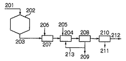
本発明による処理フローの他の例を図15に示す。図15のフローは、嫌気性消化槽202、晶析工程204、し渣の除去工程206、微粒子の分離工程208、脱水工程210からなる。なお、図15及び後述の図16及び図17のフローにおいて、脱水工程210は必須ではなく、省略することができる。
Another example of the processing flow according to the present invention is shown in FIG. The flow in FIG. 15 includes an
嫌気性消化槽202では、余剰汚泥及び/又は初沈汚泥201が投入される。嫌気性消化槽内では、約55℃、或いは、約35℃を保つように加温されている。嫌気性消化槽内で前記汚泥は、酸発酵菌、メタン生成菌の働きにより、メタン、二酸化炭素、硫化水素等のガス、水溶性の窒素、リン等に分解される。発生したメタンガスは、回収することによってエネルギー利用することが可能である。余剰汚泥のみならず、易分解性の生汚泥を投入することで、さらにメタンガスの発生量が増加する。汚泥の分解と共に、リン、マグネシウム、アンモニウムが液側に移行する。嫌気性消化槽内で、前記の各イオン濃度がMAPの溶解度積以上になると、MAPが自然発生的に生成する。MAPの析出により、ドラフトチューブや嫌気性消化槽底部、或いは汚泥の排出配管等にスケールトラブルが発生していた。
In the
通常、消化汚泥中のリン、マグネシウム、アンモニウムの比率は、概ねリン:マグネシウム:アンモニウム=100〜500:数〜数十:1000となる。リン、アンモニウムに比べ圧倒的にマグネシウム濃度が低いので、消化槽内でMAPの生成は明らかにマグネシウム濃度が律速となっている。 Usually, the ratio of phosphorus, magnesium, and ammonium in the digested sludge is approximately phosphorus: magnesium: ammonium = 100 to 500: several to several tens: 1000. Since the magnesium concentration is overwhelmingly lower than that of phosphorus and ammonium, the production of MAP is clearly rate-limiting in the digester.
後段の晶析工程204では、嫌気性消化槽202から抜き出した消化汚泥や消化脱離液に対し、マグネシウム化合物を添加することで、MAPを析出させる。このとき、曝気処理や減圧処理などを併用すると、脱炭酸してpHが上昇し、より効率的にMAPを析出させることができる。無論、水酸化ナトリウム、水酸化マグネシウム、酸化マグネシウム等の薬品を添加してpHを上昇させてもよい。添加するマグネシウム化合物としては、塩化マグネシウムのほか、水酸化マグネシウム、酸化マグネシウム、海水等を使用することができる。マグネシウムの添加量は、消化汚泥中の溶解性のオルトリン酸濃度に対し、モル比で0.1〜10、好ましくは0.5〜3.0、もっと好ましくは0.8〜1.2がよい。反応におけるpHは、7.0〜11.0、好ましくは7.5〜8.5がよい。
In the
更に、効率的にMAPを生成させるために、晶析工程204に種晶を添加しておくと好ましい。種晶は、消化槽で自然発生的に析出したMAPや、晶析工程204で析出したMAP、別途リアクターで析出したMAPを用いる。
Furthermore, it is preferable to add a seed crystal to the
図15の、本発明の他のフロー構成図に示すように、分離工程208で回収したMAPを含む微粒子等を配管213を通して晶析工程204に供給して種晶として用いることもできる。分離工程途中の分離水や、流出水等にMAPが含まれている場合は、これらを用いてもよい。
As shown in another flow configuration diagram of the present invention in FIG. 15, fine particles containing MAP recovered in the
このほか、リン鉱石やドロマイト、骨炭、活性炭、けい砂、珪酸カルシウム等の粉末或いは粒状物を種晶として用いることができる。種晶の粒径は任意でよいが、好ましくは0.05〜3.0mm、もっと好ましくは0.1〜0.5mmがよい。種晶の表面で新たなMAPを析出させることで、後段の分離工程での消化汚泥とMAPの分離が良好になる。種晶の表面でMAPを析出させるには、種晶の充填量がきわめて重要である。充填量は、リンの投入量と、種晶粒径を考慮し、種晶の表面積当たりのリン投入量(以下リン表面積負荷という)が、100g−P/m2/d以下、好ましくは30g−P/m2/d以下、もっと好ましくは10g−P/m2/d以下とするのがよい。 In addition, powder or granular materials such as phosphate ore, dolomite, bone charcoal, activated carbon, silica sand and calcium silicate can be used as seed crystals. The grain size of the seed crystal may be arbitrary, but is preferably 0.05 to 3.0 mm, more preferably 0.1 to 0.5 mm. By depositing new MAP on the surface of the seed crystal, the separation of digested sludge and MAP in the subsequent separation step is improved. In order to deposit MAP on the surface of the seed crystal, the filling amount of the seed crystal is very important. In consideration of the input amount of phosphorus and the seed crystal particle size, the filling amount is 100 g-P / m 2 / d or less, preferably 30 g- P / m 2 / d or less, more preferably 10 g-P / m 2 / d or less.
続いて消化汚泥は、し渣の除去工程206に投入される。後段の微粒子の分離工程で液体サイクロンを用いた場合、従来は、し渣の分離工程がないために、し渣等による閉塞の問題があった。そのため、長期安定処理が課題としてあった。本発明では、し渣を除去することで、後段の微粒子の分離工程208、特に液体サイクロンを用いた分離の安定性を飛躍的に向上させることができる。また、沈降分離槽の場合は、し渣と消化汚泥とMAPが混在しており、純度のよいMAPを得ることができなかった。本発明では、し渣を予め分離することで、純度の高いMAPを得ることができる。除去したし渣は、系外に排出してもよいし、図17の、本発明の別のフロー構成図に示すように、配管214を通して脱水工程210に投入してもよい。この場合、脱水性能が向上するので好ましい。
Subsequently, the digested sludge is fed into a
晶析工程204とし渣の分離工程206の順序は問わない。図15に示すように、晶析工程204、し渣の分離工程206の順でもよいし、図16に示すように、し渣の分離工程206、晶析工程204の順でもよい。
The order of the
晶析工程204及びし渣の除去工程206の後段では、消化槽内及び晶析工程で析出したMAPを含む微粒子と消化汚泥を分離する。微粒子と消化汚泥の比重差を利用して分離する方法としては、液体サイクロン、遠心沈降機、重力分離を利用した沈降分離槽などがあり、粒子径の違いを利用した微粒子の分離方法としては、振動ふるい、ドラムスクリン、ろ過層や分級層型分離層などがある。消化汚泥は粘性があり、消化汚泥中から自然沈降でMAPを分離するのは困難であるので、液体サイクロンなどの機械的な分離方法が好ましい。液体サイクロンは、下部構造が逆円錐形となっており、液体サイクロン流入管、微粒子の排出管、汚泥の排出管からなる。液体サイクロンでは、引き抜きポンプの圧送によって、MAPを含有した消化汚泥が逆円錐形の壁面を旋回流を起こしながら下降し、消化汚泥より比重の重いMAPを含む微粒子が、遠心力の働きでより下方の壁面側に集められて濃縮される。濃縮された微粒子は、連続的に或いは間欠的に抜き出す。
In the latter stage of the
本発明では、MAPを含む微粒子の分離工程208の前段でし渣を分離してあるので、液体サイクロンにおけるし渣等による閉塞の問題は解決されている。
In the present invention, since the residue is separated before the
脱水工程210では、MAPを含む微粒子を分離した消化汚泥を脱水する。脱水方法は、ベルトプレス、スクリュープレス、フィルタープレス、遠心脱水等を用いることができる。前述のように、し渣の分離工程206で分離したし渣を、脱水工程210に投入すると、脱水効果を向上させることができるので好ましい。
In the
本プロセスの後段における配管内のMAPスケールによる閉塞を防止するために、微粒子の分離工程208の後段でpHを低下させる処理、及び/又はマグネシウムイオン、リン酸イオン、アンモニウムイオンの内少なくとも1つの濃度を低下させる処理を行うことが好ましい。pHを低下させる処理としてpH調整剤の添加がある。pH調整剤としては、塩酸、硫酸、アルミニウム塩、鉄塩などがあり、消化汚泥のpHを低下させる薬品とする。アルミニウム塩、鉄塩は、消化汚泥中の溶解性のリンが固定され、溶解性濃度が低下する。
In order to prevent clogging by MAP scale in the pipe in the latter stage of the present process, a treatment for lowering the pH in the latter stage of the fine
アンモニウムイオンを低下させる処理としては、アンモニアストリッピング処理、吸着剤による固定等がある。MAPは、リン濃度、マグネシウム濃度、アンモニウム濃度、pHのいずれかが上昇すると析出する。逆に、上記のように、消化汚泥のpHを低下させたり、マグネシウムイオン、リン酸イオン、アンモニウムイオンの内少なくとも1つの濃度を低下させることで、MAPの生成能力が低下する。本発明により、MAPの生成能力が低下することで、MAPスケールが生成しにくくなった。なお、鉄塩の添加は、消化汚泥から硫化水素等の発生を抑制することができる。無論、上記の各工程は、同一の処理場にあってもよいし、各工程は別々の処理場にあり、配管輸送してもよい。 Examples of the treatment for reducing ammonium ions include ammonia stripping treatment and fixation with an adsorbent. MAP precipitates when any of phosphorus concentration, magnesium concentration, ammonium concentration, and pH increases. On the other hand, as described above, the ability to generate MAP is reduced by lowering the pH of digested sludge or reducing the concentration of at least one of magnesium ions, phosphate ions, and ammonium ions. According to the present invention, MAP scale is difficult to be generated due to a decrease in MAP generation capability. In addition, addition of iron salt can suppress generation | occurrence | production of hydrogen sulfide etc. from digested sludge. Of course, each of the above steps may be in the same treatment plant, or each step may be in a separate treatment plant and transported by piping.
以上の工程を経ることで、消化汚泥中のリンを効率的に回収することが可能となる。特に、従来、消化槽内で自然発生的に生成したMAPを回収することが困難であったが、本システムで容易に回収可能となった。 Through the above steps, phosphorus in the digested sludge can be efficiently recovered. In particular, conventionally, it has been difficult to recover MAP generated spontaneously in the digestion tank, but it can be easily recovered by this system.
図12〜図17に示すフローにおいて、晶析工程、微粒子分離工程に用いる装置として、先に説明した図1〜図10に示す各種形態の晶析リアクタ及び液体サイクロンの構成を採用することができる。 In the flow shown in FIGS. 12 to 17, as the apparatus used for the crystallization step and the fine particle separation step, the configurations of the crystallization reactor and the liquid cyclone of various forms shown in FIGS. 1 to 10 described above can be adopted. .
また、本発明においては、し渣除去装置として、穴径の異なる2種類以上のふるい体を装備した湿式振動ふるいを用いることができる。図18に、穴径の異なる2種類のふるい体を装備した2段型湿式振動ふるいを用いた処理フローの例を図18に示す。 Further, in the present invention, a wet vibration sieve equipped with two or more types of sieve bodies having different hole diameters can be used as the residue removing device. FIG. 18 shows an example of a processing flow using a two-stage wet vibrating screen equipped with two types of sieve bodies having different hole diameters.
図18は、下水処理場で発生する嫌気性消化汚泥を原汚泥1とし、汚泥中に既に存在するMAPを回収するとともに汚泥中の溶解成分であるリン酸イオンとアンモニアイオンを基質としてさらにMAPを生成し、該生成MAPを効率良く回収するための処理システムである。
FIG. 18 shows anaerobic digested sludge generated at a sewage treatment plant as
発明者らの調査によると、下水の嫌気性消化汚泥は、水処理系において鉄系またはアルミ系の添加剤が使用されていない場合においては、粒径0.1〜2.0mmの範囲内のMAP粒子を平均約0.8g/L含有する場合がある。汚泥中には、該MAP粒子以外に、し渣や、植物種子系粒子、髪の毛、藁、木屑等1.0mm以上の比較的大きな夾雑物粒子が多く混在している。図18に示すフローは、2段型振動ふるい81、晶析リアクタ9、液体サイクロン2、MAP洗浄装置82、洗浄MAPスラリーの水切り装置83により構成される。まず最初に、汚泥1を穴径の異なる2枚のふるいを装填した2段型振動ふるい81に導入する。2段型振動ふるい81においては、1段目に目の粗い方のふるい81aを、2段目に目の細かい方のふるい81bを配置する。1段目のふるい81aは、し渣等の夾雑物を分離するためのものであり、2段目のふるい81bは、粒径の大きな回収すべきMAP粒子を分離するためのものである。1段目のふるい81aでの回収物として粒径約0.8〜3.0mm以上の比較的粒子径が大きくかつ回収対象ではないし渣等の夾雑物粒子85と、1段目のふるい81aを通過し、2段目のふるい81bで回収されるものとして粒径1.0mm前後の回収すべきMAPを主体とする粒子86と、2段目のふるいの通過物として粒径0.3〜1.2mm未満程度の微粒子を含む汚泥87の3種類に分離する。上段の目の粗い方のふるい81aで分離されるし渣等の夾雑物粒子85は、汚泥から分離した後、最終的には、液体サイクロン2での微粒子回収後の微粒子脱離汚泥に添加して排出汚泥とすることができる。し渣等の夾雑物の分離によって、液体サイクロン2等での配管閉塞防止、回収MAPの純度向上が達成され、夾雑物粒子85を微粒子脱離汚泥に添加することによって排出汚泥の脱水処理性能の低下防止を図ることができる。下段の目の細かい方のふるい81bで分離されるMAPを主体とする粒子86は、後段の晶析リアクタ9を経由せずに、MAP粒子として回収することができる。また、システムの立ち上げ時等のように晶析リアクタ9内の種結晶が必要量以下に少ない場合には、下段の目の細かい方のふるいで分離されるMAPを主体とする粒子86を晶析リアクタ9に導入してもよい。下段の目の細かい方のふるいを通過した微細粒子を含有する汚泥87は、全量を後段の晶析リアクタ9に導入する。MAPを主体とする粒子86の汚泥から分離することにより、後段の晶析リアクタ9内でのMAP粒子の粒径制御、およびリアクタ9内でのMAPの堆積や配管閉塞を抑制することができる。
According to the inventors' investigation, anaerobic digested sludge of sewage is in the range of 0.1 to 2.0 mm in particle size when no iron-based or aluminum-based additive is used in the water treatment system. MAP particles may be contained in an average of about 0.8 g / L. In the sludge, in addition to the MAP particles, a large amount of relatively large particles of 1.0 mm or more such as residue, plant seed particles, hair, cocoons, and wood chips are mixed. The flow shown in FIG. 18 includes a two-
晶析リアクタ9では、必要に応じてマグネシウム源とpH調整剤を添加し、汚泥中に溶存するリン酸イオンとアンモニアイオンを基質としてMAP晶析を行う。リアクタ9内に流入する汚泥中に1.0mm以上の比較的大きなMAP粒子の量が多く含まれると、リアクタ9内の晶析反応によりこのMAP粒子が更に成長して一部のMAP粒子の粒径が数ミリ大にまで肥大化する場合がある。MAP粒子径が数ミリ大に達するとリアクタ9内や配管内の底部において堆積する場合があり閉塞トラブルの原因となる場合がある。また、MAP粒子表面にはMAP晶析反応を促進させる触媒的機能があるため、リアクタ9内の汚泥中のMAP粒子の総表面積が大きいほどMAP生成が促進されるが、リアクタ9内の汚泥中に粒径の大きいMAP粒子の比率が大きくなるとそれだけMAP重量あたりのMAP表面積が小さくなるので、MAP重量あたりの反応促進効果が減少する場合がある。しかし、一方で粒径の小さいMAP粒子の比率が大きくなると後段の液体サイクロン2等でのMAP粒子分離操作において回収率の低下を招く恐れもある。したがって、リアクタ9内のMAP粒子は、小さすぎず大きすぎず、適当な大きさに制御することが望ましい。図18に示すフローでは、このMAP晶析リアクタ9におけるMAP粒径の制御を、流入汚泥中にすでに存在するMAP粒子のうちで晶析リアクタ9に流入させるMAP粒子の粒径を調節することにより可能にした。上段の目の粗い方のふるいによって粒径の大きなMAP粒子が分離除去され、下段の目の細かい方のふるいを通過した微細粒子含有汚泥87が、全量晶析リアクタ9に導入されるが、該汚泥中のMAP粒子は所定の粒径以下の粒子のみなので晶析リアクタ9内の底部や配管内で堆積する可能性は著しく小さくなる。
In the
2段型湿式振動ふるいにおいて使用する2枚のふるいの適正穴径の設定は、夾雑物粒子85中のMAP混入率、MAP主体粒子86中のMAP純度、ふるいによるろ過抵抗と必要ろ過面積、MAP粒子径と晶析反応槽内のMAP堆積量の関係等により最適穴径の選択を行う必要がある。具体的には、1段目の夾雑物粒子分離用ふるい81aとしては0.8〜3.0mm程度の穴径、2段目のMAP主体粒子分離用ふるい81bとしては0.3〜1.2mm程度の穴径が適当である場合が多い。また、2段目のふるい81bで分離されたMAP主体粒子86は、通常、後段の晶析リアクタ9を経由せずに回収されるが、必要に応じて晶析反応槽内のMAP粒径やMAP総表面積量の変化に応じてMAP主体粒子86の一部を晶析リアクタ9に供給することも有効な場合がある。また、必要に応じて晶析リアクタ9内のMAP粒子を含む汚泥の一部または全部を、前段の2段振動ふるい81に循環することで、晶析リアクタ9内で非常に大きく成長したMAP粒子をMAP主体粒子の一部として晶析リアクタ9の外に分離することが可能となる。
The appropriate hole diameter of the two sieves used in the two-stage wet vibration sieve is determined by the MAP contamination rate in the
なお、2段目ふるい81bで分離されたMAPを主体とする粒子86は、MAP粒子洗浄装置82に導入して分級および洗浄処理を行うことができる。
The
晶析リアクタ9内で生成したMAP粒子を含む汚泥は、液体サイクロン流入管6によって液体サイクロン2に導入されてMAP粒子が濃縮される。液体サイクロン2で濃縮されたMAP粒子のスラリーは、返送管11によって晶析リアクタ9に返送することができ、また必要に応じて粒子取出管4によって適宜排出することで晶析リアクタ9内のMAP粒子濃度を調節することができる。液体サイクロン2からの濃縮MAPスラリーの一部または全部は、後段のMAP洗浄装置82に導入することができる。
Sludge containing MAP particles generated in the
MAP洗浄装置82では濃縮MAPスラリー中のMAP粒子とそれ以外の粒子を分離すると共に、洗浄水84によってMAP粒子の洗浄を行う。MAP洗浄装置82の形式としては、例えば、鉱山等で使用されている薄流選別分級装置などのような粒子の分級と洗浄を同時に行うことができる装置を採用することができる。
The
MAP洗浄装置82でMAP粒子が除去された汚泥スラリー91は、前述の2段振動ふるいの1段目ふるい81aで分離されたし渣等の夾雑物85、液体サイクロン2の溢流上昇管5より流出するMAP粒子分離後の汚泥と共に、排出汚泥88とすることができ、脱水等の処理にかけることができる。
The
MAP洗浄装置82で洗浄されたMAP粒子は、そのまま水切り装置83によって水切りを行って回収物89としてもよいし、或いは再度振動ふるい、磁力選別装置、ジグ等の分離装置で処理することによりMAPの純度を高めることも有効であり、さらには乾燥工程を採用することにより乾燥固形物状態の回収物としても良い。
The MAP particles cleaned by the
水切り装置83を通過した液90は、そのまま雑排水として水処理系に返送しても、排出汚泥88と共に脱水等の処理にかけても良い。
The liquid 90 that has passed through the draining
また、該液90にMAP粒子以外の重金属系微粒子が存在する場合には、脱水等の処理の前に、該液90を沈殿分離処理により重金属系微粒子を含んだ汚泥を分離し、上澄み液のみを脱水等の処理工程に導入するのが好ましい。上記措置により、汚泥の脱水ケーキの有効利用価値が高まる場合もあるからである。 Further, when heavy metal fine particles other than MAP particles are present in the liquid 90, the sludge containing the heavy metal fine particles is separated from the liquid 90 by precipitation separation before treatment such as dehydration, and only the supernatant liquid is obtained. Is preferably introduced into a treatment step such as dehydration. This is because the above-mentioned measures may increase the effective use value of the sludge dewatered cake.
なお、図18のフローにおいて、MAP洗浄装置82及び水切り装置83は必須の構成要件ではなく、省略することができる。
In the flow of FIG. 18, the
湿式振動ふるいとして、穴径の異なる3種類以上のふるいを組み合わせて用いることもできる。 As the wet vibration sieve, three or more kinds of sieves having different hole diameters can be used in combination.
上記のように、汚泥を予め2段振動ふるいによって処理して、し渣等の夾雑物を除去すると共に、後段の晶析リアクタ9及び液体サイクロン2での処理に先だって、汚泥中に既に含まれている粒径の大きなMAP粒子を粒径の小さなMAP微粒子を含む汚泥スラリーから分離回収することにより、晶析リアクタ9でのMAP粒子の粒径制御が容易になり、液体サイクロンが閉塞することなく、安定的に汚泥からMAP粒子を分離濃縮することが可能になる。
As described above, the sludge is treated in advance with a two-stage vibrating screen to remove impurities such as residue, and is already contained in the sludge prior to the treatment in the
上記に説明した多段型湿式振動ふるいは、図12〜図17のフローにおけるし渣除去装置として用いることができ、また、図1〜図10に示す各種形態の装置においても、し渣除去装置として用いることができる。また、上記に説明したMAP粒子洗浄装置82及び水切り装置83を、従前に説明した各種形態の処理装置において使用することができる。
The multistage wet vibration sieve described above can be used as a residue removing device in the flow of FIGS. 12 to 17, and also as a residue removing device in various types of apparatuses shown in FIGS. 1 to 10. Can be used. Further, the MAP
以下に、本発明を実施例によりさらに詳細かつ具体的に説明する。 Hereinafter, the present invention will be described in more detail and specifically with reference to examples.
実施例1〜3及び比較例1〜2は、上記で図1〜3を参照して説明した形態の実施例・比較例である。
実施例1
本実施例では、嫌気性消化の消化汚泥に、予め用意したMAPを80g/リットルとなるように添加した汚泥を原汚泥として、液体サイクロンの性能試験を確認した。装置の処理フロー図を図1に示す。
Examples 1 to 3 and Comparative Examples 1 to 2 are examples and comparative examples of the embodiment described above with reference to FIGS.
Example 1
In this example, the performance test of the liquid cyclone was confirmed by using sludge obtained by adding MAP prepared in advance to an anaerobic digestion sludge so as to be 80 g / liter. A processing flow chart of the apparatus is shown in FIG.
液体サイクロン2は2インチサイクロンを用いた。MAPの濃縮倍率を高めるために、汚泥の排出管径は15mm、微粒子の排出管径は5mmとした。液体サイクロン2への汚泥の投入流量は4m3/hr、投入圧は0.45Mpaとした。原汚泥1の供給量は0.6m3/hrで、液体サイクロン2での処理汚泥の循環量(管7によって循環される量)は3.4m3/hrであり、循環比(処理汚泥循環量/原汚泥供給量)は5.7とした。原汚泥1のMAP濃度80g/リットルに対し、処理汚泥8のMAP濃度は0.2g/リットルであり、MAPの回収率は99.8%であった。この場合の微粒子の排出管における微粒子の排出速度(kg/mm2/hr)は2.4kg/mm2/hrであり、排出速度を低く保ったことで、閉塞を起こすことなく良好に処理できた。
実施例2
この実施例では、下水処理場の消化槽から抜き出した消化汚泥を対象として、リンの除去試験を行った。処理フローを図3に示す。
As the
Example 2
In this example, a phosphorus removal test was performed on digested sludge extracted from a digester tank of a sewage treatment plant. The processing flow is shown in FIG.
処理フローは、篩方式のし渣除去装置11、晶析リアクタ9、液体サイクロン2からなる。消化汚泥1を、目開き2.0mmの振動ふるいのし渣除去装置11で処理してし渣を取り除いた後晶析リアクタ9に投入した。晶析リアクタ9には、塩化マグネシウム10を消化汚泥のオルトリン酸イオン濃度に対し、Mg/Pモル比=1となるように添加すると共に、pHを8.0となるようにpH調整剤を添加した。なお、晶析リアクタ9内のMAP濃度は40g/リットルを維持した。晶析リアクタ9内の一部の汚泥6と液体サイクロン2の処理汚泥の一部7を混合した汚泥を、連続的に液体サイクロン2に供給した。
The processing flow consists of a sieve-type
液体サイクロンは、2インチサイクロンを用いた。MAPの濃縮倍率を高めるために、汚泥の排出管径は15mm、微粒子の排出管系は5mmとした。液体サイクロン2への汚泥の投入流量は4m3/hr、投入圧は0.45Mpaとした。
As the liquid cyclone, a 2-inch cyclone was used. In order to increase the concentration rate of MAP, the sludge discharge pipe diameter was 15 mm and the fine particle discharge pipe system was 5 mm. The input flow rate of sludge to the
なお、本実施例並びに晶析リアクタ9と液体サイクロン2とを組み合わせて用いる以下の実施例・比較例においては、液体サイクロンで濃縮された結晶スラリは、通常は晶析リアクタに返送し、原水のリン濃度などの性状から予測されるMAP析出量に基づいて、適宜(例えば一日に一回又は複数回)排出管より適当量を排出・回収した。
In this example and the following examples and comparative examples in which the
原汚泥1の供給量は0.25m3/hrであり、液体サイクロン2への汚泥の供給量は、晶析リアクタ内の汚泥6が0.5m3/hr、サイクロン2での処理汚泥の循環量が3.5m3/hrで、合計4m3/hr、循環比は7とした。
The supply rate of
原汚泥1のT−P800mg/リットル、PO4−P300mg/リットルに対し、処理汚泥8のT−Pは350mg/リットル、PO4−Pは10mg/リットルであり、リンの回収率は56%であった。回収物は、95%以上がMAPであった。なお、この場合の微粒子の排出管における微粒子の排出速度(kg/mm2/hr)は1.0kg/mm2/hrであり、排出速度を低く保ったことで、閉塞を起こすことなく良好に処理できた。
実施例3
この実施例は、原汚泥のMAP濃度を55g/Lとして、循環比(循環汚泥量/原汚泥量)を変えて通泥した場合の閉塞状況を確認した例である。処理フローは図1のフローを用いた。液体サイクロン2としては2インチサイクロンを用いて、オーバー径(汚泥排出管径)は14mm、アンダー径(微粒子排出管径)は5mmとした。サイクロン2への汚泥投入流量は循環汚泥(7)量と原汚泥量を合わせて4m3/hrとした。
T-P800mg / liter
Example 3
In this example, the MAP concentration of the raw sludge was 55 g / L, and the blockage situation was confirmed when the circulation ratio (circulated sludge amount / raw sludge amount) was changed and passed. The processing flow shown in FIG. 1 was used. As the
循環比と循環後のMAP濃度(サイクロン2へ投入される汚泥のMAP濃度)との関係を図19に示す。循環比0.01と0.05の場合はサイクロンアンダ(サイクロン2の底部及び微粒子排出管)が閉塞し、処理できなかった。循環比0.1以上では、閉塞することなく良好に処理を行うことができた。この結果より、汚泥の循環比は0.1以上とすることが望ましいことが分かった。
比較例1(実施例1の比較例)
この比較例は実施例1の比較例である。実施例1と同様に、濃度80g/リットルのMAPを含む汚泥を原汚泥として、液体サイクロンの性能試験を行った。装置のフロー図を図20に示す。
FIG. 19 shows the relationship between the circulation ratio and the MAP concentration after circulation (the MAP concentration of sludge introduced into the cyclone 2). When the circulation ratio was 0.01 and 0.05, the cyclone under (the bottom of the
Comparative Example 1 (Comparative Example of Example 1)
This comparative example is a comparative example of Example 1. In the same manner as in Example 1, the performance test of the hydrocyclone was performed using sludge containing MAP having a concentration of 80 g / liter as raw sludge. A flow chart of the apparatus is shown in FIG.
液体サイクロン2は実施例1と同様のものを用いた。原汚泥1の供給量は4m3/hrで、液体サイクロン2での処理汚泥8は返送せず、循環量(処理汚泥循環量/原汚泥供給量)はゼロとした。原汚泥1を液体サイクロン2に通水開始して1分以内に閉塞し、分離は不能となった。原汚泥1中のMAP濃度が高いために、閉塞したと判断できる。この場合の微粒子の排出管における微粒子の排出速度(kg/mm2/hr)は、16kg/mm2/hrであり、循環比がゼロであったことから排出速度が高く閉塞したと考えられる。
比較例2(実施例2の比較例)
この比較例は、実施例2の比較例である。実施例2と同様の汚泥を原汚泥とした。処理フローを図21に示す。処理フローは実施例2と同様に、し渣の除去装置11、晶析リアクタ9、液体サイクロン2からなる。
The
Comparative Example 2 (Comparative Example of Example 2)
This comparative example is a comparative example of Example 2. The sludge similar to Example 2 was used as the raw sludge. The processing flow is shown in FIG. As in the second embodiment, the processing flow includes a
晶析リアクタ9は、実施例2と同様に、塩化マグネシウム10を消化汚泥のオルトリン酸イオン濃度に対し、Mg/Pモル比=1となるように添加すると共に、pHを8.0となるようにpH調整剤を添加した。なお、晶析リアクタ9内のMAP濃度は40g/リットルを維持した。
In the
原汚泥の供給量は0.25m3/hrで循環比(処理汚泥循環量/原汚泥供給量)はゼロ、晶析リアクタ9内の汚泥は、間欠的に4m3/hrで液体サイクロン2に供給した。
The supply rate of raw sludge is 0.25 m 3 / hr, the circulation ratio (treated sludge circulation rate / raw sludge supply rate) is zero, and the sludge in the
原汚泥のT−P800mg/リットル、PO4−P300mg/リットルに対し、処理汚泥8のT−Pは900mg/リットル、PO4−Pは10mg/リットルであり、リンの回収率は−13%であった。処理汚泥のT−Pが原汚泥より増加していることから、リアクタ内のMAPが流出したと考えられる。この場合の微粒子の排出管における微粒子の排出速度(kg/mm2/hr)は8.0kg/mm2/hrであり、閉塞こそしなかったものの、排出速度が速いことで処理汚泥中にMAP粒子が流出し、回収率が低かった。
実施例4
実施例4〜8及び比較例3〜4は、上記で図4〜6を参照して説明した形態の実施例・比較例である。
T-P800mg / l of the raw sludge, with respect to PO 4 -P300mg / l, T-P of the treated
Example 4
Examples 4 to 8 and Comparative Examples 3 to 4 are examples and comparative examples of the embodiment described above with reference to FIGS.
実施例4では、下水処理場の消化槽から抜き出した消化汚泥を対象として、リンをりん酸マグネシウムアンモニウムの形態で回収する試験を行った。処理フローを図22に示す。 In Example 4, the test which collect | recovers phosphorus in the form of magnesium ammonium phosphate was done for the digested sludge extracted from the digestion tank of a sewage treatment plant. The processing flow is shown in FIG.
処理フローは、篩方式のし査除去装置11、晶析リアクタ9、液体サイクロン2、循環水槽55からなる。消化汚泥1を、目開き2.0mmの振動ふるいのし渣除去装置11で処理してし渣を取り除いた後晶析リアクタ9に投入した。
The processing flow includes a sieve-type inspection /
晶析リアクタ9では、塩化マグネシウム10を消化汚泥のオルトリン酸イオン濃度に対し、Mg/Pモル比=1となるように添加すると共に、リアクタ9内のpHをpH計57でモニターしながらpHを8.0となるようにpH調整剤を添加した。なお、晶析リアクタ9内のMAP濃度は80g/Lを維持した。
In the
リアクタ9の底部に接続された粒子の引抜管52から抜出した粒子は、液体サイクロン投入管6に供給し、循環水と共に連続的に液体サイクロン2に供給した。液体サイクロン2としては、2インチサイクロンを用いた。液体サイクロン2の汚泥の排出管径は14mm、粒子の排出管径は9.4mmとした。液体サイクロン2への投入流量は4m3/hr、投入圧は0.40Mpaとした。液体サイクロンの溢流上昇管5からの流出水は、全量を晶析リアクタ9に接続された返送管51に返送した。
The particles extracted from the
なお、晶析リアクタ9への汚泥供給量は0.25m3/hr、晶析リアクタ9からの汚泥引抜量は1.5m3/hrとした。
The amount of sludge supplied to the
原汚泥1のT−P800mg/L、PO4−P300mg/Lに対し、処理汚泥8のT−Pは350mg/L、PO4−Pは10mg/Lであり、リンの回収率は56%であった。回収物は95%以上がMAPであった。
実施例5
この実施例では、ゴミ浸出水の処理に当たり、炭酸カルシウム粒子を析出させることでカルシウム塩の除去を行った。処理装置は、晶析リアクタ9と液体サイクロン2、循環水槽55からなる。処理フローを図23に示す。
Example 5
In this example, the calcium salt was removed by precipitating calcium carbonate particles in the treatment of the waste leachate. The processing apparatus includes a
晶析リアクタ9では、ゴミ浸出水(以下原水という)をリアクタ9底部に供給するとともに、5%炭酸ナトリウム水溶液も同様にリアクタ9底部に供給した。炭酸ナトリウムの添加量は、晶析リアクタ9へ投入する汚泥のカルシウム濃度に対してC/Caモル比=1:1とした。反応pHは8.0とした。なお、晶析リアクタ9内の炭酸カルシウム濃度は80g/Lを維持した。
In the
晶析リアクタ9の粒子の引抜管52から抜出した粒子は液体サイクロン流入管6に供給して、循環水と共に連続的に液体サイクロン2に供給した。液体サイクロン2としては、2インチサイクロンを用いた。液体サイクロン2の汚泥の排出管径は14mm、粒子の排出管系は9.4mmとした。液体サイクロンへの投入流量は4m3/hr、投入圧は0.40Mpaとした。
The particles extracted from the
なお、晶析リアクタ9への原汚泥供給量は0.25m3/hr、晶析リアクタ9からのMAP粒子を含む汚泥の引抜量は1.5m3/hrとした。
The amount of raw sludge supplied to the
原水1がpH7.2、Ca濃度3000mg/Lであったのに対し、処理水8のpHは8.0、Ca濃度は100mg/Lでありカルシウムの除去率は95%以上であった。
比較例3(実施例4の比較例)
この比較例は実施例4の比較例である。実施例4と同様の汚泥を原汚泥とした。処理フローを図24に示す。処理フローは、実施例4と同様にし査の除去装置11、晶析リアクタ9、液体サイクロン2からなる。以下に特に説明する事項以外は実施例4と同様に処理を行った。
Comparative Example 3 (Comparative Example of Example 4)
This comparative example is a comparative example of Example 4. The sludge similar to Example 4 was used as the raw sludge. The processing flow is shown in FIG. The processing flow is the same as that of the fourth embodiment, and includes the
晶析リアクタ9では、実施例4と同様に、塩化マグネシウムを消化汚泥のオルトリン酸イオン濃度に対し、Mg/Pモル比=1となるように添加すると共に、pHを8.0となるようにpH調整剤を添加した。なお、運転に先立ち、晶析装置内のMAP濃度は80g/Lとした。
In the
晶析リアクタ9への原汚泥1の供給量は0.25m3/hr、晶析リアクタ9内の汚泥は引抜管52によって間欠的に4m3/hrで液体サイクロン2に供給した。液体サイクロン2への汚泥の供給は、レベル計(L)の数値によってon−off制御した。
The supply amount of the
原汚泥のT−P800mg/L、PO4−P300mg/Lに対し、処理汚泥のT−Pは900mg/L、PO4−Pは10mg/Lであり、リンの回収率は−13%であった。運転して3時間後、サイクロンのアンダ(微粒子排出管)が閉塞した。本システムでは、安定した処理を行うことは困難であった。
比較例4(実施例4の比較例)
この比較例は実施例4の比較例である。実施例4と同様の汚泥を原汚泥とした。処理フローを図25に示す。処理フローは、し査の除去装置11、晶析リアクタ9、液体サイクロン2、循環水槽55からなる。以下に特に説明する事項以外は実施例4と同様に処理を行った。
Raw sludge of T-P800mg / L, relative to PO 4 -P300mg / L, T- P of the treated sludge is 900mg / L, PO 4 -P is 10 mg / L, the phosphorus recovery rate is met -13% It was. Three hours after the operation, the cyclone under (fine particle discharge pipe) was blocked. In this system, it was difficult to perform stable processing.
Comparative Example 4 (Comparative Example of Example 4)
This comparative example is a comparative example of Example 4. The sludge similar to Example 4 was used as the raw sludge. The processing flow is shown in FIG. The processing flow consists of a
晶析リアクタ9では、塩化マグネシウム10を消化汚泥のオルトリン酸イオン濃度に対し、Mg/Pモル比=1となるように添加すると共に、pHを8.0となるようにpH調整剤を添加した。なお、晶析装置内のMAP濃度は80g/Lを維持した。
In the
晶析リアクタ9底部の粒子の引抜管52から抜出した粒子は液体サイクロン流入管6に供給し、循環水と共に連続的に液体サイクロン2に供給した。液体サイクロン2としては2インチサイクロンを用いた。液体サイクロン2の汚泥の排出管径は14mm、粒子の排出管系は9.4mmとした。液体サイクロン2への投入流量は4m3/hr、投入圧は0.40Mpaとした。液体サイクロンへの投入水の供給は、晶析リアクタ9内のレベル計(L)の数値によってon−off制御した。液体サイクロンの溢流上昇管5から流出する汚泥は全量循環水槽に供給した。
The particles extracted from the
なお、晶析リアクタ9への原汚泥1の供給量は0.25m3/hr、晶析リアクタ9からの汚泥の引抜量は1.5m3/hrとした。
The amount of
原汚泥1のT−P800mg/L、PO4−P300mg/Lに対し、処理汚泥8のT−Pは400mg/L、PO4−Pは10mg/Lであり、リンの回収率は50%であった。回収物は、95%以上がMAPであった。
実施例4と比較すると、回収率が低下したばかりか、水位が変動したり、リアクタ内の粒子濃度が変動することで処理水質が変動するなど、安定性に欠けた。
実施例6
この実施例では、下水処理場の消化槽から抜き出した消化汚泥を対象として、リンをりん酸マグネシウムアンモニウム(MAP)の形態で回収する試験を行った。処理フローを図26に示す。液体サイクロンを2台直列に設置してMAP粒子の回収率の向上を図った。
Compared with Example 4, not only the recovery rate decreased, but also the water level fluctuated, and the treated water quality fluctuated due to fluctuations in the concentration of particles in the reactor.
Example 6
In this example, a test for recovering phosphorus in the form of magnesium ammonium phosphate (MAP) was performed on digested sludge extracted from a digester tank of a sewage treatment plant. The processing flow is shown in FIG. Two liquid cyclones were installed in series to improve the recovery rate of MAP particles.
処理フローは、篩方式のし査除去装置11、晶析リアクタ9、液体サイクロン2台2,2’、循環水槽55からなる。以下に特に説明する事項以外は実施例4と同様に処理を行った。
The processing flow includes a sieve-type inspection /
晶析リアクタ9では、塩化マグネシウム10を消化汚泥1のオルトリン酸イオン濃度に対し、Mg/Pモル比=1となるように添加すると共に、pHを8.0となるようにpH調整剤を添加した。なお、晶析装置内のMAP濃度は80g/Lを維持した。
In the
晶析リアクタ9底部の粒子の引抜管52から抜出したMAP粒子は液体サイクロン流入管6に供給して循環水と共に連続的に液体サイクロン2に供給した。液体サイクロン2としては2インチサイクロンを用いた。液体サイクロン2の汚泥の排出管径は14mm、粒子の排出管系は9.4mmとした。液体サイクロンへの流入水の投入流量は4m3/hr、投入圧は0.40Mpaとした。液体サイクロンの溢流上昇管5から流出する汚泥は、全量を晶析リアクタ9に接続された返送管51に返送した。
The MAP particles extracted from the
なお、晶析リアクタ9への原汚泥1の供給量は0.25m3/hr、晶析リアクタ9からの汚泥の引抜量は1.5m3/hrとした。
The amount of
2段目のサイクロン2’は、1段目サイクロン2と同じ2インチサイクロンであり、1段目のサイクロン2の溢流上昇管5から流出した微粒子を更に回収する目的で設置した。循環水槽55からの流出水を2段目のサイクロン2’に投入した。2段目サイクロン2’への投入流量は4m3/hrで間欠運転とした。
The second-stage cyclone 2 'is the same 2-inch cyclone as the first-
原汚泥1のT−P800mg/L、PO4−P300mg/Lに対し、処理汚泥8のT−Pは320mg/L、PO4−Pは10mg/Lであり、リンの回収率は60%であった。サイクロンを2段直列に設置することで、リンの回収率が上昇した。
実施例7
この実施例では、下水処理場の余剰汚泥の濃縮工程分離水(以下原水という)から、リンをヒドロキシアパタイトで形態で回収する試験を行った。処理フローを図27に示す。
Example 7
In this example, a test was conducted to recover phosphorus in the form of hydroxyapatite from the separated water (hereinafter referred to as raw water) of the excess sludge in the sewage treatment plant. The processing flow is shown in FIG.
処理フローは、晶析リアクタ9、液体サイクロン2、循環水槽55からなる。以下に特に説明する事項以外は実施例4と同様に処理を行った。
The processing flow includes a
晶析リアクタ9には、予め種晶としてリン鉱石を浮遊させた。塩化カルシウムを原水のオルトリン酸イオン濃度に対し、Ca/P重量比=5.6となるように添加すると共に、pHを8.3となるようにpH調整剤を添加した。なお、晶析リアクタ9内のリン鉱石濃度は80g/Lを維持した。
In the
晶析リアクタ9底部の粒子の引抜管52から抜出した粒子は、液体サイクロン流入管6に供給して循環水と共に連続的に液体サイクロン2に供給した。液体サイクロンとしては2インチサイクロンを用いた。液体サイクロン2の汚泥の排出管径は14mm、粒子の排出管系は9.4mmとした。液体サイクロン2への投入流量は4m3/hr、投入圧は0.40Mpaとした。
The particles extracted from the
なお、晶析リアクタ9への原水供給量は0.25m3/hr、晶析リアクタ9からの汚泥の引抜量は1.5m3/hrとした。液体サイクロンの溢流上昇管5から流出する汚泥は、全量を晶析リアクタ9に接続された返送管51に返送した。
The amount of raw water supplied to the
原水のT−P46mg/L、PO4−P45mg/Lに対し、処理水のT−Pは3.2mg/L、PO4−Pは2.0mg/Lであり、リンの回収率は93%であった。
実施例8
この実施例では、半導体製造工場廃水(以下原水という)から、フッ素をフッ化カルシウムで形態で回収する試験を行った。処理フローを図28に示す。
Raw water T-P46mg / L, relative to PO 4 -P45mg / L, T- P of the treated water is 3.2mg / L, PO 4 -P is 2.0 mg / L, the
Example 8
In this example, a test was conducted to recover fluorine in the form of calcium fluoride from semiconductor manufacturing factory wastewater (hereinafter referred to as raw water). The processing flow is shown in FIG.
処理フローは、晶析リアクタ9、液体サイクロン2、循環水槽55からなる。
The processing flow includes a
晶析リアクタ9では、予め種晶としてフッ化カルシウム結晶を浮遊させた。塩化カルシウムを原水のフッ素イオン濃度に対し、Ca/F重量比=1.5となるように添加すると共に、pHを6.5となるようにpH調整剤を添加した。なお、晶析リアクタ9内のフッ化カルシウム濃度は80g/Lを維持した。
In the
晶析リアクタ9の底部の粒子の引抜管52から抜出した粒子は、液体サイクロン流入管6に供給して循環水と共に連続的に液体サイクロン2に供給した。液体サイクロン2としては2インチサイクロンを用いた。液体サイクロン2の汚泥の排出管径は14mm、粒子の排出管系は9.4mmとした。液体サイクロン2への投入流量は4m3/hr、投入圧は0.40Mpaとした。
The particles extracted from the
なお、晶析リアクタ9への原水1の供給量は0.15m3/hr、晶析リアクタ9からの粒子を含む汚泥の引抜量は1.5m3/hrとした。
The supply amount of
原水1のフッ素濃度600mg/Lに対し、処理水8のフッ素は8mg/Lであり、フッ素の回収率は95%以上であった。
実施例9
実施例9〜11及び比較例5は、上記で図7〜10を参照して説明した形態の実施例・比較例である。下水処理場の消化槽から抜き出した消化汚泥を対象として、リンの除去試験を行った。汚泥を晶析リアクタに投入する前に実施例2と同じし渣除去装置でし渣の除去を行った。
The fluorine concentration of the treated
Example 9
Examples 9 to 11 and Comparative Example 5 are examples and comparative examples in the form described above with reference to FIGS. A phosphorus removal test was conducted on digested sludge extracted from the digestion tank of the sewage treatment plant. Before the sludge was put into the crystallization reactor, the residue was removed with the same residue removing apparatus as in Example 2.
実施例9の処理フローを図29に示す。処理フローは、晶析装置9、2段の並列に設置した液体サイクロン2からなる。
FIG. 29 shows a processing flow of the ninth embodiment. The processing flow consists of a
消化汚泥をふるい方式のし渣除去装置で処理した後に晶析リアクタ9に投入した。晶析リアクタ9では、塩化マグネシウム10を消化汚泥のオルトリン酸イオン濃度に対し、Mg/Pモル比=1となるように添加すると共に、pHを8.0となるようにpH調整剤を添加した。液体サイクロン2は2インチサイクロンを用いた。液体サイクロン2の汚泥の排出管径は14mm、微粒子の排出管系は8mmとした。晶析リアクタ9の底部から抜出した汚泥6と液体サイクロンの溢流上昇管5から流出する処理汚泥の一部を混合した汚泥を、返送管7によって連続的に液体サイクロン2に供給した。液体サイクロン1台への投入流量は4m3/hr、投入圧は0.45Mpaとした。
The digested sludge was treated with a sieve-type residue removing device and then charged into the
原汚泥の流入量を流量計71でモニターし、原汚泥1の流入量が0.25m3/hr以下の場合は、液体サイクロン1台のみが起動し、0.25〜0.5m3/hrの場合は、2台が起動するようにポンプ72のon−off制御を行った。
The flow rate of raw sludge is monitored with a
原汚泥1の流入量が0.15〜0.50m3/hrで変動したにもかかわらず、晶析リアクタ9内のMAP濃度は100g/L以上を維持できた。原汚泥1のT−Pは800mg/L、PO4−Pは300mg/Lに対し、処理汚泥8のT−Pは350mg/L、PO4−Pは10mg/Lであり、リンの回収率は56%であった。回収物は、95%以上がMAPであった。
実施例10
この実施例では、晶析リアクタ9に汚泥濃度計73を設置し、リアクタ9内の汚泥濃度をモニタリングすることで、液体サイクロン2の稼動台数を制御した。処理フローを図30に示す。なお、モニタリングで測定された汚泥濃度とMAP濃度の変換は、予め作成した検量線で行った。
The MAP concentration in the
Example 10
In this example, a
処理フローは、晶析リアクタ9、2段の液体サイクロン2からなる。以下に特に説明する事項以外は実施例9と同様に処理を行った。
The processing flow consists of a
晶析リアクタ9と液体サイクロン2は実施例9と同様とした。晶析リアクタの底部から抜出した汚泥6と液体サイクロンの溢流上昇管5から流出する処理汚泥の一部を混合した汚泥は、返送管7によって連続的に液体サイクロン2に供給した。液体サイクロン1台への投入流量は4m3/hr、投入圧は0.45Mpaとした。
The
リアクタ9内のMAP濃度が100g/L以下となったら、液体サイクロン2を2台稼動させ、100g/Lを超えたら1台停止して1台で運転するようにポンプ72を制御した。
When the MAP concentration in the
原汚泥の流量が0.15〜0.50m3/hrで変動したにもかかわらず、処理汚泥の性状は安定した。原汚泥のT−Pは800mg/L、PO4−Pは300mg/Lに対し、処理汚泥のT−Pは350mg/L、PO4−Pは10mg/Lであり、リンの回収率は56%であった。回収物は、95%以上がMAPであった。
実施例11
この実施例では、図31に示すような処理フローを用いて処理を行った。嫌気性消化槽で余剰汚泥を35℃で嫌気性消化した消化汚泥1を原汚泥として用いた。液体サイクロンの溢流上昇管から流出する処理汚泥のpHとリン濃度をモニタリングし、過飽和度を算出して、算出値に基づいて液体サイクロンの稼働台数を制御した。
Although the flow rate of the raw sludge varied from 0.15 to 0.50 m 3 / hr, the properties of the treated sludge were stable. Raw sludge TP is 800 mg / L, PO 4 -P is 300 mg / L, treated sludge TP is 350 mg / L, PO 4 -P is 10 mg / L, and phosphorus recovery is 56 %Met. Over 95% of the recovered material was MAP.
Example 11
In this example, processing was performed using a processing flow as shown in FIG. Digested
処理フローは、晶析リアクタ9、2段の液体サイクロン2からなる。以下に特に説明する事項以外は実施例9と同様に処理を行った。
The processing flow consists of a
晶析リアクタ9と液体サイクロン2は実施例9と同様とした。晶析リアクタの底部から抜出した汚泥6と液体サイクロンの溢流上昇管5から流出する処理汚泥の一部を混合した汚泥は、返送管7によって連続的に液体サイクロン2に供給した。液体サイクロン1台への投入流量は4m3/hr、投入圧は0.45Mpaとした。
The
液体サイクロンの溢流上昇管5から流出する処理汚泥8のpHとリン濃度を、リン濃度計74及びpH計75でモニターした。モニタリング装置では、pH電極、比色法によってpHとリン酸態リンイオン濃度を測定した。なお、リン酸態リン濃度は汚泥をpH3としてMAPを溶解させて測定した。ちなみにpH3で生物由来のリンの溶出は確認されなかった。
The pH and phosphorus concentration of the treated
モニタリング装置で測定したpH、リン酸態リンイオン濃度と、アンモニア性窒素600mg/L、Mg50mg/Lを用いて過飽和度比を算出した。過飽和度比が25以下の場合は液体サイクロンの稼動台数は1台として、25を超えた場合2台とした。 The supersaturation ratio was calculated using the pH and phosphate phosphorus ion concentration measured with the monitoring device, and 600 mg / L ammonia nitrogen and 50 mg / L Mg. When the supersaturation ratio is 25 or less, the number of operating liquid cyclones is one, and when it exceeds 25, the number is two.
原汚泥の流量が0.15〜0.50m3/hrで変動したにもかかわらず、処理汚泥の性状は安定した。原汚泥のT−Pは800mg/L、PO4−Pは300mg/Lに対し、処理汚泥のT−Pは350mg/L、PO4−Pは10mg/Lであり、リンの回収率は56%であった。回収物は、95%以上がMAPであった。過飽和度比が高くなったのは、微細MAPが多数析出したためであり、この場合、液体サイクロンの稼動台数を2台とすることで、晶析リアクタ内のMAP濃度を高めることで、回収率が上昇した。 Although the flow rate of the raw sludge varied from 0.15 to 0.50 m 3 / hr, the properties of the treated sludge were stable. Raw sludge TP is 800 mg / L, PO 4 -P is 300 mg / L, treated sludge TP is 350 mg / L, PO 4 -P is 10 mg / L, and phosphorus recovery is 56 %Met. Over 95% of the recovered material was MAP. The supersaturation ratio was increased because a large amount of fine MAP was precipitated. In this case, the recovery rate was increased by increasing the MAP concentration in the crystallization reactor by using two hydrocyclones. Rose.
比較例5(実施例9の比較)
この比較例は実施例9の比較例であり、実施例9同様のリンの除去試験を行った。処理フローを図32に示す。
Comparative Example 5 (Comparison of Example 9)
This comparative example is a comparative example of Example 9, and a phosphorus removal test similar to Example 9 was performed. The processing flow is shown in FIG.
処理フローは、晶析リアクタ9、1段の液体サイクロン2からなる。
The processing flow consists of a
晶析リアクタ9への汚泥の投入並びに晶析リアクタ9の運転、及び液体サイクロンの運転に関しては実施例9と同様とした。晶析リアクタ9の底部から抜出した汚泥6と液体サイクロンの溢流上昇管5から流出する処理汚泥の一部を混合した汚泥は、液体サイクロン流入管6によって連続的に液体サイクロン2に供給した。液体サイクロンへの投入流量は4m3/hr、投入圧は0.45Mpaとした。
The introduction of sludge into the
原汚泥1の流量に関わらず、液体サイクロンは1台で運転した。
Regardless of the flow rate of
原汚泥の流量は0.15〜0.50m3/hrで変動し、晶析リアクタ9内のMAP濃度は100g/L以上を維持できず、原汚泥のT−Pは800mg/L、PO4−Pは300mg/Lに対し、処理汚泥のT−Pは350〜450mg/Lで変動した。PO4−Pは10mg/Lで概ね一定であったことから、リアクタ9内のMAP濃度が低下した時に、微細なMAPが多数析出したと考えられる。実施例9に比べ処理安定性に欠けた。
The raw sludge flow rate fluctuates from 0.15 to 0.50 m 3 / hr, the MAP concentration in the
実施例12〜14及び比較例6は、上記で図12〜14を参照して説明した形態の実施例・比較例である。 Examples 12 to 14 and Comparative Example 6 are examples and comparative examples in the form described above with reference to FIGS.
実施例12では、図12に示すような処理フローを用いて処理を行った。対象有機性廃棄物は、嫌気好気法の余剰汚泥とした。処理フローは、嫌気性消化槽、脱炭酸槽として曝気槽、し渣の分離工程、微粒子の分離工程とした。嫌気性消化槽に投入する汚泥量は90L/dとした。消化日数は20日、消化温度は35℃とした。消化槽内の消化汚泥は、引抜汚泥として1日に約90L/dを排出した。引き抜いた汚泥は、曝気することでpHを上昇させた。曝気時間は2時間として、空気の吹き込み量は40L/minとした。し渣の分離工程は、目開き2.0mmの振動ふるいによってし渣を取り除いた。脱炭酸及びし渣を除去した消化汚泥は、4インチの液体サイクロンで消化汚泥とMAPを含む微粒子に分離した。 In Example 12, processing was performed using a processing flow as shown in FIG. The target organic waste was surplus sludge from the anaerobic-aerobic method. The treatment flow was an anaerobic digestion tank, a decarbonation tank, an aeration tank, a residue separation process, and a fine particle separation process. The amount of sludge thrown into the anaerobic digester was 90 L / d. The digestion days were 20 days and the digestion temperature was 35 ° C. Digested sludge in the digestion tank was discharged about 90 L / d per day as drawn sludge. The extracted sludge raised the pH by aeration. The aeration time was 2 hours, and the air blowing rate was 40 L / min. In the step of separating the screen residue, the screen residue was removed with a vibrating screen having an aperture of 2.0 mm. The digested sludge from which decarbonation and residue were removed was separated into fine particles containing digested sludge and MAP with a 4-inch liquid cyclone.
なお、脱炭酸工程、し渣の分離工程、微粒子の分離工程は半回分的に行った。各工程の水質を表1に示す。 The decarboxylation step, the residue separation step, and the fine particle separation step were performed semi-batch. Table 1 shows the water quality of each process.
嫌気性消化に投入した汚泥(投入汚泥という)のTSは42g/L、VSは35g/L、T−Pは920mg/Lであった。嫌気性消化槽から引抜いた汚泥(引き抜き汚泥という)の成分は、pHが7.2、TSが21g/L、VSが17g/L、T−Pが920mg/L、溶解性のPO4−Pは300mg/L、溶解性のマグネシウムは15mg/Lであった。 TS of the sludge input into the anaerobic digestion (referred to as input sludge) was 42 g / L, VS was 35 g / L, and TP was 920 mg / L. The components of the sludge extracted from the anaerobic digestion tank (referred to as extracted sludge) are pH 7.2, TS 21 g / L, VS 17 g / L, TP 920 mg / L, soluble PO 4 -P Was 300 mg / L, and soluble magnesium was 15 mg / L.
引き抜き汚泥を曝気してpHを8.2に上昇させた後、溶解性のマグネシウム濃度を測定したところ、3mg/Lまで低下した。微粒子の分離工程で回収したMAPを含む微粒子量は、1.9g/Lであり、そのうちMAPは1.5g/Lであった。 After extracting the sludge and raising the pH to 8.2, the soluble magnesium concentration was measured and found to be 3 mg / L. The amount of fine particles containing MAP recovered in the fine particle separation step was 1.9 g / L, of which MAP was 1.5 g / L.
上記の処理を行った消化汚泥を、模擬的に内径130mmのステンレス製の配管に、連続通水した。配管内の汚泥の滞留時間は15日とした。約3ヵ月後の配管内の様態は、特にスケールらしい結晶は見られなかった。予め設置していたテストピースに付着したスケール量は、わずか2gであった。上記の処理を行ったことで、スケールの生成が防止できたと判断できる。 The digested sludge subjected to the above treatment was continuously passed through a stainless steel pipe having an inner diameter of 130 mm in a simulated manner. The sludge residence time in the piping was 15 days. About 3 months later, the appearance in the pipes did not show any particular scale-like crystals. The amount of scale attached to the test piece installed in advance was only 2 g. It can be determined that scale generation could be prevented by performing the above processing.

実施例13
この実施例では、図12に示すような処理フローを用いて処理を行った。対象有機性廃棄物は、嫌気好気法の余剰汚泥とした。処理フローは、嫌気性消化槽、脱炭酸槽として減圧処理、し渣の分離工程、微粒子の分離工程とした。嫌気性消化槽に投入する汚泥量は90L/dとした。消化日数は20日、消化温度は35℃とした。消化槽内の消化汚泥は、引抜汚泥として1日に約90L/dを排出した。
Example 13
In this example, processing was performed using a processing flow as shown in FIG. The target organic waste was surplus sludge from the anaerobic-aerobic method. The treatment flow was an anaerobic digestion tank and a decarbonation tank under reduced pressure, a residue separation step, and a fine particle separation step. The amount of sludge thrown into the anaerobic digester was 90 L / d. The digestion days were 20 days and the digestion temperature was 35 ° C. Digested sludge in the digestion tank was discharged about 90 L / d per day as drawn sludge.
引き抜いた汚泥は、減圧することでpHを上昇させた。真空度は−94kPa、回転体の回転速度は1650rpmとした。 The extracted sludge was depressurized to raise the pH. The degree of vacuum was -94 kPa, and the rotational speed of the rotating body was 1650 rpm.
し渣の分離工程は、目開き2.0mmの振動ふるいによってし渣を取り除いた。脱炭酸及びし渣を除去した消化汚泥は、4インチの液体サイクロンで消化汚泥とMAPを含む微粒子に分離した。 In the step of separating the screen residue, the screen residue was removed with a vibrating screen having an aperture of 2.0 mm. The digested sludge from which decarbonation and residue were removed was separated into fine particles containing digested sludge and MAP with a 4-inch liquid cyclone.
なお、脱炭酸工程、し渣の分離工程、微粒子の分離工程は半回分的に行った。
各工程の水質を表2に示す。
The decarboxylation step, the residue separation step, and the fine particle separation step were performed semi-batch.
Table 2 shows the water quality of each process.
嫌気性消化に投入した汚泥(投入汚泥という)のTSは42g/L、VSは35g/L、T−Pは920mg/Lであった。嫌気性消化槽から引抜いた汚泥(引き抜き汚泥という)の成分は、pHが7.2、TSが21g/L、VSが17g/L、T−Pが920mg/L、溶解性のPO4−Pは300mg/L、溶解性のマグネシウムは15mg/Lであった。 TS of the sludge input into the anaerobic digestion (referred to as input sludge) was 42 g / L, VS was 35 g / L, and TP was 920 mg / L. The components of the sludge extracted from the anaerobic digestion tank (referred to as extracted sludge) are pH 7.2, TS 21 g / L, VS 17 g / L, TP 920 mg / L, soluble PO 4 -P Was 300 mg / L, and soluble magnesium was 15 mg / L.
引き抜き汚泥を曝気してpHを8.2に上昇させた後、溶解性のマグネシウム濃度を測定したところ、3mg/Lまで低下した。微粒子の分離工程で回収したMAPを含む微粒子量は、1.9g/Lであり、そのうちMAPは1.5g/Lであった。 After extracting the sludge and raising the pH to 8.2, the soluble magnesium concentration was measured and found to be 3 mg / L. The amount of fine particles containing MAP recovered in the fine particle separation step was 1.9 g / L, of which MAP was 1.5 g / L.
上記の処理を行った消化汚泥を、模擬的に内径130mmのステンレス製の配管に、連続通水した。配管内の汚泥の滞留時間は15日とした。約3ヵ月後の配管内の様態は、特にスケールらしい結晶は見られなかった。予め設置していたテストピースに付着したスケール量はわずか2gであった。上記の処理を行ったことで、スケールの生成が防止できたと判断できる。 The digested sludge subjected to the above treatment was continuously passed through a stainless steel pipe having an inner diameter of 130 mm in a simulated manner. The sludge residence time in the piping was 15 days. About 3 months later, the appearance in the pipes did not show any particular scale-like crystals. The amount of scale attached to the test piece installed in advance was only 2 g. It can be determined that scale generation could be prevented by performing the above processing.
実施例14
この実施例では、図33に示すような処理フローを用いて処理を行った。対象有機性廃棄物は、嫌気好気法の余剰汚泥とした。処理フローは、リンの吐出し槽と脱水工程、濃度調整工程、嫌気性消化槽、脱炭酸槽(曝気槽)、し渣の分離工程、微粒子の分離工程とした。余剰汚泥のリンの吐き出し槽における滞留時間は1日とした。嫌気性消化槽、脱炭酸槽(曝気槽)、し渣の分離工程、微粒子の分離工程は実施例1と同様とした。各工程の水質を表3に示す。
Example 14
In this example, processing was performed using a processing flow as shown in FIG. The target organic waste was surplus sludge from the anaerobic-aerobic method. The treatment flow was a phosphorus discharge tank, a dehydration process, a concentration adjustment process, an anaerobic digestion tank, a decarbonation tank (aeration tank), a residue separation process, and a fine particle separation process. The residence time of the excess sludge in the phosphorus discharge tank was 1 day. The anaerobic digestion tank, decarboxylation tank (aeration tank), residue separation process, and fine particle separation process were the same as in Example 1. Table 3 shows the water quality of each process.
濃縮余剰汚泥の性状は、TSは42g/L、VSは35g/L、T−Pは920mg/L、PO4−Pは20mg/L、溶解性のMgは10mg/Lであった。リンの吐き出し工程の出口の性状は、溶解性のPO4−PとMgが上昇して、PO4−Pが300mg/L、Mgが100mg/Lとなった。リン吐き出し後の濃縮余剰汚泥を脱水した後、下水2次処理水で汚泥のTSを42g/Lとなるように調整した。調整後の性状は、TSは42g/L、VSは35g/L、TPは600mg/L、PO4−Pは60mg/L、溶解性のMgは20mg/Lであった。 The properties of the concentrated excess sludge were 42 g / L for TS, 35 g / L for VS, 920 mg / L for TP, 20 mg / L for PO 4 -P, and 10 mg / L for soluble Mg. The properties at the outlet of the phosphorus discharge process were as follows: soluble PO 4 -P and Mg increased, and PO 4 -P was 300 mg / L and Mg was 100 mg / L. After dewatering the concentrated excess sludge after phosphorus discharge, the TS of the sludge was adjusted to 42 g / L with sewage secondary treated water. The properties after adjustment were 42 g / L for TS, 35 g / L for VS, 600 mg / L for TP, 60 mg / L for PO 4 -P, and 20 mg / L for soluble Mg.
引き抜き汚泥の性状は、TSは20g/L、VSは17g/L、T−Pは600mg/L、PO4−Pは180mg/L、溶解性のMgは20mg/Lであった。引き抜き汚泥を曝気してpHを8.2に上昇させた後、溶解性のマグネシウム濃度を測定したところ3mg/Lまで低下した。 The properties of the drawn sludge were 20 g / L for TS, 17 g / L for VS, 600 mg / L for TP, 180 mg / L for PO 4 -P, and 20 mg / L for soluble Mg. The extracted sludge was aerated to raise the pH to 8.2, and then the soluble magnesium concentration was measured and found to be 3 mg / L.
微粒子の分離工程で回収したMAPを含む微粒子量は、0.3g/Lであり、そのうちMAPは0.25g/Lであった。 The amount of fine particles containing MAP recovered in the fine particle separation step was 0.3 g / L, of which MAP was 0.25 g / L.
上記の処理を行った消化汚泥を、模擬的に内径130mmのステンレス製の配管に、連続通水した。配管内の汚泥の滞留時間は15日とした。約3ヵ月後の配管内の様態は、特にスケールらしい結晶は見られなかった。予め設置していたテストピースに付着したスケール量は、わずか2gであった。上記の処理を行ったことで、スケールの生成が防止できたと判断できる。 The digested sludge subjected to the above treatment was continuously passed through a stainless steel pipe having an inner diameter of 130 mm in a simulated manner. The sludge residence time in the piping was 15 days. About 3 months later, the appearance in the pipes did not show any particular scale-like crystals. The amount of scale attached to the test piece installed in advance was only 2 g. It can be determined that scale generation could be prevented by performing the above processing.
比較例6
以下において、実施例12と比較した結果を示す。比較例6は、図34に示すように、脱炭酸工程、し渣の分離工程と微粒子の分離工程がないこと以外は実施例12と同じである。各工程の水質を表4に示す。
Comparative Example 6
Below, the result compared with Example 12 is shown. As shown in FIG. 34, Comparative Example 6 is the same as Example 12 except that there is no decarboxylation step, residue separation step, and fine particle separation step. Table 4 shows the water quality of each process.
投入汚泥のTSは42g/L、VSは35g/L、T−Pは920mg/Lであった。引抜汚泥の成分は、TSが21g/L、VSが17g/L、T−Pが920mg/L、PO4−Pが300mg/L、溶解性のMgが9mg/Lであった。上記の処理を行った消化汚泥を、模擬的に内径130mmのステンレス製の配管に、連続通水した。配管内の汚泥の滞留時間は15日とした。約3ヵ月後の配管内の様態は、配管壁面に約3mm程度、スケールが生成されていた。スケールをX線回折装置及び蛍光X線装置で成分分析を行ったところ、MAPであることが分かった。消化汚泥中のMAPが堆積したり、配管途中で脱炭酸等によりpH変動があり、MAPが生成したと考えられる。 The input sludge had a TS of 42 g / L, a VS of 35 g / L, and a TP of 920 mg / L. The components of the drawn sludge were 21 g / L for TS, 17 g / L for VS, 920 mg / L for TP, 300 mg / L for PO 4 -P, and 9 mg / L for soluble Mg. The digested sludge subjected to the above treatment was continuously passed through a stainless steel pipe having an inner diameter of 130 mm in a simulated manner. The sludge residence time in the piping was 15 days. About 3 months later, the scale inside the pipe had a scale of about 3 mm. Component analysis of the scale with an X-ray diffractometer and a fluorescent X-ray apparatus revealed that it was MAP. It is considered that MAP was generated due to accumulation of MAP in the digested sludge or pH fluctuation due to decarboxylation or the like in the middle of the piping.
実施例15
実施例15及び比較例7は、上記で図15〜17を参照して説明した形態の実施例・比較例である。
Example 15
Example 15 and Comparative Example 7 are examples and comparative examples of the embodiment described above with reference to FIGS.
実施例15では、図15にしめすような処理フローを用いて処理を行った。対象有機性廃棄物は、嫌気好気法の余剰汚泥とした。 In Example 15, processing was performed using the processing flow shown in FIG. The target organic waste was surplus sludge from the anaerobic-aerobic method.
処理フローは、嫌気性消化槽、晶析槽、し渣の分離工程、微粒子の分離工程とした。嫌気性消化槽に投入する汚泥量は90L/dとした。消化日数は20日、消化温度は35℃とした。消化槽内の消化汚泥は、引抜汚泥として1日に約90L/dを排出した。晶析槽では、塩化マグネシウムを消化汚泥のオルトリン酸イオン濃度に対し、Mg/Pモル比=1となるように添加すると共に、pHを8.0となるようにpH調整剤を添加した。また、微粒子の分離工程で回収したMAPを含む微粒子を種晶として7kg添加した。 The treatment flow was an anaerobic digestion tank, a crystallization tank, a residue separation step, and a fine particle separation step. The amount of sludge thrown into the anaerobic digester was 90 L / d. The digestion days were 20 days and the digestion temperature was 35 ° C. Digested sludge in the digestion tank was discharged about 90 L / d per day as drawn sludge. In the crystallization tank, magnesium chloride was added so that the Mg / P molar ratio = 1 with respect to the orthophosphate ion concentration of the digested sludge, and a pH adjuster was added so that the pH was 8.0. Moreover, 7 kg of fine particles containing MAP recovered in the fine particle separation step were added as seed crystals.
し渣の分離工程は、目開き2.0mmの振動ふるいを用いた。 In the screen residue separation process, a vibrating screen having a mesh size of 2.0 mm was used.
微粒子の分離工程は、4インチの液体サイクロンを用いた。 In the fine particle separation process, a 4-inch hydrocyclone was used.
なお、嫌気性消化槽以外の工程は半回分的に行った。
各工程の水質を表5に示す。
In addition, processes other than an anaerobic digester were performed semi-batch.
Table 5 shows the water quality of each step.
嫌気性消化に投入した汚泥(投入汚泥)のTSは42g/L、VSは35g/L、T−Pは920mg/Lであった。嫌気性消化槽から引抜いた汚泥(引き抜き汚泥:消化汚泥)の成分は、pHが7.2、TSが21g/L、VSが17g/L、T−Pが920mg/L、溶解性のPO4−Pは300mg/Lであった。晶析槽の流出汚泥の性状は、pHが8.0、TSが24g/L、VSが17g/L、T−Pが920mg/L、溶解性のPO4−Pは10mg/Lであった。微粒子の分離工程で回収したMAPを含む微粒子量は、消化汚泥1L当たり4.3gであり、そのうちMAPは4.0gであった。また、流出汚泥の性状はpHが8.0、TSが19g/L、VSが17g/L、T−Pが440mg/L、溶解性のPO4−Pは10mg /Lであった。消化汚泥に投入したリン濃度920mg/Lの内、480mg/Lが回収された。
TS of the sludge input to the anaerobic digestion (input sludge) was 42 g / L, VS was 35 g / L, and TP was 920 mg / L. The components of the sludge extracted from the anaerobic digestion tank (extracted sludge: digested sludge) are pH 7.2, TS 21 g / L, VS 17 g / L, TP 920 mg / L, soluble PO 4. -P was 300 mg / L. The effluent sludge in the crystallization tank had a pH of 8.0, TS of 24 g / L, VS of 17 g / L, TP of 920 mg / L, and soluble PO 4 -P of 10 mg / L. . The amount of fine particles containing MAP recovered in the fine particle separation step was 4.3 g per liter of digested sludge, of which MAP was 4.0 g. The properties of the spilled sludge were pH 8.0, TS 19 g / L, VS 17 g / L, TP 440 mg / L, and soluble PO 4 -
比較例7
以下において、実施例15と比較した結果を示す。比較例7は、図35に示すように、晶析工程、し渣の分離工程、微粒子の分離工程がないこと以外は実施例15と同じである。各工程の水質を表6に示す。
Comparative Example 7
Below, the result compared with Example 15 is shown. As shown in FIG. 35, Comparative Example 7 is the same as Example 15 except that there is no crystallization step, residue separation step, and fine particle separation step. Table 6 shows the water quality of each process.
投入汚泥のTSは42g/L、VSは35g/L、T−Pは920mg/Lであった。引抜汚泥の成分は、TSが21g/L、VSが17g/L、T−Pが920mg/L、PO4−Pが300mg/Lであった。また、引抜汚泥中にMAPが1.5g/L含まれていた。引き抜き汚泥中のMAPは、回収されることなく脱水された後、焼却処分された。 The input sludge had a TS of 42 g / L, a VS of 35 g / L, and a TP of 920 mg / L. The components of the drawn sludge were 21 g / L for TS, 17 g / L for VS, 920 mg / L for TP, and 300 mg / L for PO 4 -P. Moreover, 1.5 g / L of MAP was contained in the drawn sludge. The MAP in the extracted sludge was dewatered without being recovered and then incinerated.
以上の比較例におけるリン回収量はゼロであった。
実施例16
この実施例では、先に示した図18の処理フローと全く同じフローを用いて汚泥の処理を行った。フローの詳細については、図18に関する説明を参照されたい。対象汚泥はA下水処理場の嫌気性消化汚泥とし、対象回収物は汚泥中で生成したMAPとした。本フローでの消化汚泥の処理速度は5m3/日であり、運転を3ヶ月行った。
The phosphorus recovery amount in the above comparative examples was zero.
Example 16
In this example, the sludge was treated using the same flow as that shown in FIG. For details of the flow, refer to the description regarding FIG. The target sludge was anaerobic digested sludge from the A sewage treatment plant, and the target recovered material was MAP generated in the sludge. The digested sludge treatment speed in this flow was 5 m 3 / day, and the operation was performed for 3 months.
2段型振動ふるい81のふるい目は、A下水処理場汚泥の性状分析結果を基に上段81aが2.0mm、下段81bが0.5mmと設定した。上段ふるい81aにより分離された分離物(し渣等の夾雑物)85は、液体サイクロン2の溢流上昇管5から流出するMAP脱離汚泥及びMAP微粒子洗浄装置82からのMAP脱離汚泥91に添加して排出汚泥として排出した。上段ふるい81aを通過し下段ふるい81bを通過しなかった分離物(MAP結晶を主体とする粒子)は、直接MAP洗浄装置82に導入した。下段ふるい81bを通過した分離物(微細粒子を含む汚泥スラリー)は、MAP晶析リアクタ9に導き、塩化マグネシウムと苛性ソーダを必要に応じて添加して晶析反応を行わせた。MAP晶析リアクタ9内のMAP粒子を含む汚泥は液体サイクロン流入管6により2インチ液体サイクロン2に適宜導入し、サイクロン2により濃縮されたMAP粒子は返送管11によってMAP晶析リアクタ9に戻し、適宜その一部を粒子排出管4によってMAP洗浄装置82に導入した。MAP洗浄装置82としては、ドラム型の薄流選別分級装置を用いて、導入されたMAP粒子を含むスラリーからMAP粒子を分級・分離すると共に洗浄水84で洗浄した。分離・洗浄後のMAP粒子は水切り装置83によって水切りを行った後、MAP結晶89として回収した。
The sieve of the two-
また、比較フローとして1段型振動ふるいを使用して、同じ対象汚泥に対して同様の処理を行った。比較フローのフロー図を図36に示す。図36に示す比較フローでは、振動ふるいとして、穴径2.0mmの1段ふるい91を用い、分離されたし渣等の夾雑物92を排出汚泥として排出すると共に、ふるいを通過したMAP微粒子を含む汚泥スラリー93を全量晶析リアクタ9に投入した。他の条件は、図18に示すフローと同じとした。
Moreover, the same process was performed with respect to the same object sludge, using a 1 step type vibration sieve as a comparison flow. A flow chart of the comparison flow is shown in FIG. In the comparative flow shown in FIG. 36, as a vibration sieve, a one-
実施例16の結果を表7に示す。 The results of Example 16 are shown in Table 7.
本システムの目的は、下水汚泥中からできるだけ純度の高いMAPをできるだけ多く回収することを目的とする。そこで、本システムの評価項目は「処理汚泥1LあたりのMAP回収量」と「回収MAP純度」の2項目とした。 The purpose of this system is to collect as much MAP as possible from sewage sludge as much as possible. Therefore, the evaluation items of this system were two items of “MAP recovery amount per liter of treated sludge” and “recovered MAP purity”.
図18に示す2段ふるいを用いたフローによる処理法では、MAP回収量が平均3.9g/L、回収MAP純度が平均86.6%であったのに対して、図36に示す1段ふるいを用いた処理フローでは、MAP回収量が平均3.5g/L、回収MAP純度が平均82.7%であった。2段型ふるいを用いたフローの方が1段型ふるいを用いたフローよりもMAP回収量で0.4g/L増加し10%以上向上した上、MAP純度は4.2ポイント向上した。1段型振動ふるいを使用する方式では、数ミリ大に成長したMAP粒子がシステム内配管や反応槽内に一部沈積する場合があり、これによりMAP回収量が低下したものと考えられる。また、2.0mm以下のゴマや木屑等MAP以外の微粒子が1段ふるいを通過してMAP粒子とともにMAP晶析リアクタ9に導入され、このMAP以外の微粒子の表面にMAPの晶析物が付着した粒子が形成され、その粒子が後段のMAP洗浄装置でMAPとともに回収されて回収MAP純度を低下させたり、或いは回収物から除外されてMAP回収量を低下させると推測される。これに対して、2段ふるいを用いたフローにおいては、穴径2mmの1段目ふるいを通過したゴマや木屑等MAP以外の微粒子は、粒径の大きなMAP粒子と共に2段目ふるいで分離され、晶析リアクタを経由しないで直接MAP洗浄装置に送られるので、晶析リアクタでの反応に関与しない。この結果、MAP回収量およびMAP純度は、2段ふるいを用いた方式の方が相対的に良好な処理結果が得られたと考えられる。
In the processing method using the flow using the two-stage sieve shown in FIG. 18, the MAP recovery amount averaged 3.9 g / L and the recovery MAP purity averaged 86.6%, whereas the one-stage process shown in FIG. In the processing flow using a sieve, the MAP recovery amount averaged 3.5 g / L, and the recovery MAP purity averaged 82.7%. The flow using the two-stage sieve increased by 0.4 g / L in the amount of MAP recovered by 10% or more, and the MAP purity improved by 4.2 points over the flow using the first-stage sieve. In the method using a single-stage vibrating screen, MAP particles that have grown to several millimeters may be partially deposited in the system piping or reaction tank, which is thought to reduce the amount of MAP recovered. In addition, fine particles other than MAP such as sesame and wood chips of 2.0 mm or less pass through the first stage sieve and are introduced into the
本発明によれば、汚泥中のリンをMAP粒子として回収する処理において、液体サイクロンなどの粒子分離装置の閉塞を抑制し、処理の安定性を向上させ、純度の高いMAPを得ることができるなどの効果が得られる。本発明は、汚泥中のリンをMAP粒子として回収する処理のみならず、各種排水中からの様々な結晶の分離回収に適用することができる。 According to the present invention, in the process of recovering phosphorus in sludge as MAP particles, blockage of a particle separator such as a hydrocyclone can be suppressed, the stability of the process can be improved, and a high-purity MAP can be obtained. The effect is obtained. The present invention can be applied not only to the process of recovering phosphorus in sludge as MAP particles but also to the separation and recovery of various crystals from various wastewaters.
1:汚泥
2:液体サイクロン
3:MAP
4:排出管
5:溢流上昇管
6:液体サイクロン流入管
7:返送管A
8:処理汚泥
9:晶析リアクタ
10:薬品
11:返送管B
11:し渣除去装置
51:返送管
52:引抜管
53:微粒子排出管
54:循環水流入管
55:循環水槽
56:MAP回収管
57:pH計
71:流量計
72:ポンプ
73:濃度計
74:リン濃度計
75:pH計
81:二段型振動ふるい
82:MAP洗浄装置
83:水切り装置
84:洗浄水
85:分離物
86:MAPを主体とする粒子
87:微細粒子含有汚泥
88:排出汚泥
89:MAP結晶回収物
91:MAP粒子が除去された汚泥スラリー
92:夾雑物
93:MAP粒子を含む汚泥スラリー
101:投入汚泥
102:嫌気性消化槽
103:消化汚泥(引き抜き汚泥)
104:脱炭酸工程
105:し渣の除去工程
106:し渣
107:MAPを含む微粒子の分離工程
108:MAPを含む微粒子回収
109:系外へ
110:pH調整剤
111:濃縮余剰汚泥
112:リン吐き出し槽
113:BOD源
114:濃縮工程
115:分離水
116:脱水工程
117:濃度調整水
118:脱離液
201:投入汚泥
202:嫌気性消化槽
203:引き抜き汚泥(消化汚泥)
204:晶析工程
205:Mg化合物
206:し渣の除去工程
207:し渣
208:MAPを含む微粒子の分離工程
209:MAPを含む微粒子回収
210:脱水工程
211:脱離液
212:系外へ
213:微粒子移送配管
214:し渣移送配管
1: Sludge 2: Hydrocyclone 3: MAP
4: Discharge pipe 5: Overflow riser pipe 6: Hydrocyclone inflow pipe 7: Return pipe A
8: treated sludge 9: crystallization reactor 10: chemical 11: return pipe B
11: Screen removal device 51: Return pipe 52: Extraction pipe 53: Fine particle discharge pipe 54: Circulating water inflow pipe 55: Circulating water tank 56: MAP recovery pipe 57: pH meter 71: Flow meter 72: Pump 73: Concentration meter 74: Phosphorus concentration meter 75: pH meter 81: Two-stage vibration sieve 82: MAP cleaning device 83: Draining device 84: Washing water 85: Separation material 86: Particles mainly composed of MAP 87: Sludge containing fine particles 88: Discharged sludge 89 : MAP crystal recovery
91: Sludge slurry from which MAP particles have been removed 92: Contaminant 93: Sludge slurry containing MAP particles 101: Input sludge 102: Anaerobic digestion tank 103: Digested sludge (drawn sludge)
104: Decarbonation step 105: Screen residue removal step 106: Screen residue 107: Separation step of fine particles containing MAP 108: Recovery of fine particles containing MAP 109: Outside the system 110: pH adjuster 111: Concentrated excess sludge 112: Phosphorus Discharge tank 113: BOD source 114: Concentration process 115: Separation water 116: Dehydration process 117: Concentration adjustment water 118: Desorption liquid 201: Input sludge 202: Anaerobic digestion tank 203: Extracted sludge (digested sludge)
204: Crystallization process 205: Mg compound 206: Screen residue removal process 207: Screen residue 208: Separation process of fine particles containing MAP 209: Collection of fine particles containing MAP 210: Dehydration process 211: Desorbed liquid 212: Outside the system 213: Fine particle transfer pipe 214: Sediment transfer pipe
Claims (6)
前記汚泥又は分離水に薬品を添加することによって結晶を析出させる晶析リアクタと、
前記晶析リアクタに該リアクタ内から汚泥又は結晶を含む液を引き抜く引抜き管と、
前記引抜き管から引き抜いた液から結晶を分離する第一の液体サイクロン(X)と、
前記第一の液体サイクロン(X)の溢流上昇管から流出した分離水を循環水として受け入れて上部に該循環水の越流部と前記晶析リアクタの底部で連通部とを有する返送管(C)と、
前記第一の液体サイクロン(X)で分離又は濃縮した結晶を前記晶析リアクタへ返送する返送管(B)とを設け、
前記晶析リアクタ内で沈降させて引き抜いた液を前記返送管(C)から流出する循環水の一部とともに前記第一の液体サイクロン(X)に導入する配管を設けたことを特徴とする結晶の分離装置。 In an apparatus for separating sludge, or crystals contained therein, from the separated water by the sludge concentration or dehydration treatment,
A crystallization reactor for precipitating crystals by adding chemicals to the sludge or separated water;
A drawing tube for drawing a liquid containing sludge or crystals from the inside of the crystallization reactor;
A first hydrocyclone (X) for separating crystals from the liquid drawn from the drawing tube;
A return pipe that receives the separated water flowing out from the overflow ascending pipe of the first hydrocyclone (X) as circulating water, and has an overflow part of the circulating water at the top and a communicating part at the bottom of the crystallization reactor ( C) and
A return pipe (B) for returning the crystal separated or concentrated by the first liquid cyclone (X) to the crystallization reactor;
A crystal is provided, wherein a pipe for introducing the liquid settled and extracted in the crystallization reactor into the first liquid cyclone (X) together with a part of circulating water flowing out from the return pipe (C) is provided. Separation device.
Priority Applications (1)
| Application Number | Priority Date | Filing Date | Title |
|---|---|---|---|
| JP2009206963A JP4523069B2 (en) | 2005-01-21 | 2009-09-08 | Wastewater and sludge treatment equipment |
Applications Claiming Priority (3)
| Application Number | Priority Date | Filing Date | Title |
|---|---|---|---|
| JP2005013552 | 2005-01-21 | ||
| JP2005013551 | 2005-01-21 | ||
| JP2009206963A JP4523069B2 (en) | 2005-01-21 | 2009-09-08 | Wastewater and sludge treatment equipment |
Related Parent Applications (1)
| Application Number | Title | Priority Date | Filing Date |
|---|---|---|---|
| JP2006553983A Division JP4402697B2 (en) | 2005-01-21 | 2006-01-23 | Wastewater and sludge treatment equipment |
Publications (2)
| Publication Number | Publication Date |
|---|---|
| JP2010012467A true JP2010012467A (en) | 2010-01-21 |
| JP4523069B2 JP4523069B2 (en) | 2010-08-11 |
Family
ID=36692384
Family Applications (2)
| Application Number | Title | Priority Date | Filing Date |
|---|---|---|---|
| JP2006553983A Active JP4402697B2 (en) | 2005-01-21 | 2006-01-23 | Wastewater and sludge treatment equipment |
| JP2009206963A Active JP4523069B2 (en) | 2005-01-21 | 2009-09-08 | Wastewater and sludge treatment equipment |
Family Applications Before (1)
| Application Number | Title | Priority Date | Filing Date |
|---|---|---|---|
| JP2006553983A Active JP4402697B2 (en) | 2005-01-21 | 2006-01-23 | Wastewater and sludge treatment equipment |
Country Status (4)
| Country | Link |
|---|---|
| US (1) | US7402245B2 (en) |
| EP (1) | EP1849751B1 (en) |
| JP (2) | JP4402697B2 (en) |
| WO (1) | WO2006078012A1 (en) |
Cited By (10)
| Publication number | Priority date | Publication date | Assignee | Title |
|---|---|---|---|---|
| JP2008006405A (en) * | 2006-06-30 | 2008-01-17 | Ebara Corp | Treatment apparatus for water or sludge containing ion in liquid |
| WO2014030788A1 (en) * | 2012-08-23 | 2014-02-27 | 뉴엔텍(주) | High-efficiency system for reducing weight of sludge |
| WO2014030786A1 (en) * | 2012-08-23 | 2014-02-27 | 뉴엔텍(주) | System for drawing sludge in digester |
| JP2014104432A (en) * | 2012-11-28 | 2014-06-09 | Swing Corp | Sludge treatment apparatus and method of manufacturing phosphorus |
| JP2016190190A (en) * | 2015-03-31 | 2016-11-10 | 株式会社石垣 | Sludge treatment system and sludge treatment method |
| KR101706013B1 (en) * | 2016-04-11 | 2017-02-13 | 성균관대학교산학협력단 | Cyclone devices and plants for wastewater treatment comprising the same |
| JP2018075555A (en) * | 2016-11-11 | 2018-05-17 | 水ing株式会社 | Apparatus and method for treatment of organic effluent and organic sludge |
| JP2019522611A (en) * | 2016-05-20 | 2019-08-15 | キャンビ・テクノロジー・アクシェルスカブCambi Technology As | Phosphate recovery method |
| JP2021507805A (en) * | 2017-12-18 | 2021-02-25 | ヴェオリア・ウォーター・ソリューションズ・アンド・テクノロジーズ・サポート | Sludge disposal method |
| WO2021040499A1 (en) * | 2019-08-30 | 2021-03-04 | 허관용 | Ammonium removal apparatus and method using chemical treatment of wastewater generated by dehydrating digested sludge |
Families Citing this family (12)
| Publication number | Priority date | Publication date | Assignee | Title |
|---|---|---|---|---|
| JP5715350B2 (en) * | 2010-06-29 | 2015-05-07 | 株式会社タクマ | Methane fermentation residue dewatering system |
| CN103201050B (en) | 2010-11-16 | 2016-09-21 | 日清制粉集团本社股份有限公司 | Powder classification device |
| DK3138677T3 (en) * | 2013-10-21 | 2020-06-22 | Re Match Uk Ltd | PROCEDURE TO SEPARATE FILLING PROVIDED FROM AN ARTICLE GRASS PRODUCT |
| EP2904892A1 (en) * | 2014-02-11 | 2015-08-12 | Morten Toft | Method and system for extracting at least a part of the phosphorous and/or nitrogen content of slurry and use of a mobile slurry distribution system as a crystallisation container |
| JP6592406B2 (en) * | 2016-06-10 | 2019-10-16 | 水ing株式会社 | Crystallizer, methane fermentation facility, and scale prevention method in methane fermentation facility |
| WO2018185025A1 (en) * | 2017-04-06 | 2018-10-11 | Universiteit Gent | Method for recovering n, k, and p from liquid waste stream |
| CN110183059A (en) * | 2019-06-24 | 2019-08-30 | 上海华畅环保设备发展有限公司 | The method and apparatus of eddy flow rotation reinforcing waste water short-cut nitrification and denitrification |
| US20220356099A1 (en) * | 2019-06-26 | 2022-11-10 | Panasonic Intellectual Property Management Co., Ltd. | Water softening system and water softening device |
| JP2021155771A (en) * | 2020-03-25 | 2021-10-07 | 住友金属鉱山株式会社 | Treatment method for ore slurry, and hydrometallurgical method for nickel oxide ore |
| CN112142285B (en) * | 2020-09-08 | 2021-03-30 | 江阴市晨辉市政建设工程有限责任公司 | Ecological environment-friendly septic tank |
| CN112792102A (en) * | 2021-01-14 | 2021-05-14 | 中铁三局集团桥隧工程有限公司 | Shield muck environment-friendly treatment method |
| CN113402134A (en) * | 2021-06-02 | 2021-09-17 | 大连大学 | Silt solidification treatment device |
Citations (8)
| Publication number | Priority date | Publication date | Assignee | Title |
|---|---|---|---|---|
| JP2002102603A (en) * | 2000-09-29 | 2002-04-09 | Mitsubishi Gas Chem Co Inc | Crystallization method and device |
| JP2002336875A (en) * | 2001-05-17 | 2002-11-26 | Ebara Corp | Recovering method and equipment for phosphorus in water |
| JP2003047973A (en) * | 2001-08-02 | 2003-02-18 | Ebara Corp | Dephosphorization method and apparatus |
| JP2004000941A (en) * | 2002-04-18 | 2004-01-08 | Ebara Corp | Treatment method for organic wastewater or sludge and treatment apparatus therefor |
| JP2004160340A (en) * | 2002-11-12 | 2004-06-10 | Ebara Corp | Method and equipment for treating organic waste water and sludge |
| JP2004160300A (en) * | 2002-11-11 | 2004-06-10 | Ebara Corp | Method of treating organic waste water and sludge, and treatment apparatus thereof |
| JP2004167307A (en) * | 2002-11-18 | 2004-06-17 | Ebara Corp | Method and apparatus for removing/recovering phosphorus from organic sewage |
| WO2004067139A1 (en) * | 2003-01-31 | 2004-08-12 | Ebara Corporation | Method and apparatus for removing ion in fluid by crystallization |
Family Cites Families (10)
| Publication number | Priority date | Publication date | Assignee | Title |
|---|---|---|---|---|
| JPH0777640B2 (en) * | 1986-09-26 | 1995-08-23 | 福岡市 | Dephosphorization device |
| JP2576679B2 (en) * | 1990-10-01 | 1997-01-29 | 福岡市 | Dephosphorization device |
| JPH06312111A (en) * | 1993-04-28 | 1994-11-08 | Kubota Corp | Filtration machine |
| JPH0813276B2 (en) | 1993-10-28 | 1996-02-14 | 国立衛生試験所長 | Novel lambda phage DNA and its use |
| JP2811408B2 (en) | 1993-11-12 | 1998-10-15 | 株式会社荏原製作所 | Continuous deaerator |
| JPH09192532A (en) * | 1996-01-16 | 1997-07-29 | Daido Steel Co Ltd | Powder classifying apparatus |
| JP4724894B2 (en) * | 1999-10-28 | 2011-07-13 | 株式会社Ihi | Solid separation device |
| JP2002336898A (en) | 2001-05-15 | 2002-11-26 | Ebara Corp | Method and device for methane fermentation of sludge |
| JP4053273B2 (en) | 2001-10-12 | 2008-02-27 | 株式会社荏原製作所 | Reaction crystallization method and apparatus |
| JP2004025055A (en) * | 2002-06-26 | 2004-01-29 | Unitika Ltd | Treatment method of returned water from sludge treatment |
-
2006
- 2006-01-19 US US11/334,387 patent/US7402245B2/en not_active Expired - Fee Related
- 2006-01-23 WO PCT/JP2006/300947 patent/WO2006078012A1/en active Application Filing
- 2006-01-23 EP EP06712163.2A patent/EP1849751B1/en not_active Expired - Fee Related
- 2006-01-23 JP JP2006553983A patent/JP4402697B2/en active Active
-
2009
- 2009-09-08 JP JP2009206963A patent/JP4523069B2/en active Active
Patent Citations (8)
| Publication number | Priority date | Publication date | Assignee | Title |
|---|---|---|---|---|
| JP2002102603A (en) * | 2000-09-29 | 2002-04-09 | Mitsubishi Gas Chem Co Inc | Crystallization method and device |
| JP2002336875A (en) * | 2001-05-17 | 2002-11-26 | Ebara Corp | Recovering method and equipment for phosphorus in water |
| JP2003047973A (en) * | 2001-08-02 | 2003-02-18 | Ebara Corp | Dephosphorization method and apparatus |
| JP2004000941A (en) * | 2002-04-18 | 2004-01-08 | Ebara Corp | Treatment method for organic wastewater or sludge and treatment apparatus therefor |
| JP2004160300A (en) * | 2002-11-11 | 2004-06-10 | Ebara Corp | Method of treating organic waste water and sludge, and treatment apparatus thereof |
| JP2004160340A (en) * | 2002-11-12 | 2004-06-10 | Ebara Corp | Method and equipment for treating organic waste water and sludge |
| JP2004167307A (en) * | 2002-11-18 | 2004-06-17 | Ebara Corp | Method and apparatus for removing/recovering phosphorus from organic sewage |
| WO2004067139A1 (en) * | 2003-01-31 | 2004-08-12 | Ebara Corporation | Method and apparatus for removing ion in fluid by crystallization |
Cited By (11)
| Publication number | Priority date | Publication date | Assignee | Title |
|---|---|---|---|---|
| JP2008006405A (en) * | 2006-06-30 | 2008-01-17 | Ebara Corp | Treatment apparatus for water or sludge containing ion in liquid |
| WO2014030788A1 (en) * | 2012-08-23 | 2014-02-27 | 뉴엔텍(주) | High-efficiency system for reducing weight of sludge |
| WO2014030786A1 (en) * | 2012-08-23 | 2014-02-27 | 뉴엔텍(주) | System for drawing sludge in digester |
| JP2014104432A (en) * | 2012-11-28 | 2014-06-09 | Swing Corp | Sludge treatment apparatus and method of manufacturing phosphorus |
| JP2016190190A (en) * | 2015-03-31 | 2016-11-10 | 株式会社石垣 | Sludge treatment system and sludge treatment method |
| KR101706013B1 (en) * | 2016-04-11 | 2017-02-13 | 성균관대학교산학협력단 | Cyclone devices and plants for wastewater treatment comprising the same |
| JP2019522611A (en) * | 2016-05-20 | 2019-08-15 | キャンビ・テクノロジー・アクシェルスカブCambi Technology As | Phosphate recovery method |
| JP2018075555A (en) * | 2016-11-11 | 2018-05-17 | 水ing株式会社 | Apparatus and method for treatment of organic effluent and organic sludge |
| JP2021507805A (en) * | 2017-12-18 | 2021-02-25 | ヴェオリア・ウォーター・ソリューションズ・アンド・テクノロジーズ・サポート | Sludge disposal method |
| US11440828B2 (en) | 2017-12-18 | 2022-09-13 | Veolia Water Solutions & Technologies Support | Method of treating sludge |
| WO2021040499A1 (en) * | 2019-08-30 | 2021-03-04 | 허관용 | Ammonium removal apparatus and method using chemical treatment of wastewater generated by dehydrating digested sludge |
Also Published As
| Publication number | Publication date |
|---|---|
| US20060163134A1 (en) | 2006-07-27 |
| US7402245B2 (en) | 2008-07-22 |
| JPWO2006078012A1 (en) | 2008-06-19 |
| JP4402697B2 (en) | 2010-01-20 |
| EP1849751A1 (en) | 2007-10-31 |
| EP1849751A4 (en) | 2011-03-23 |
| WO2006078012A1 (en) | 2006-07-27 |
| EP1849751B1 (en) | 2014-07-30 |
| JP4523069B2 (en) | 2010-08-11 |
Similar Documents
| Publication | Publication Date | Title |
|---|---|---|
| JP4402697B2 (en) | Wastewater and sludge treatment equipment | |
| US7431834B2 (en) | Waste water and sludge treatment apparatus | |
| JP4743627B2 (en) | Water or sludge treatment equipment containing ions in liquid | |
| EP1593417A1 (en) | Method and apparatus for removing ion in fluid by crystallization | |
| JP6592406B2 (en) | Crystallizer, methane fermentation facility, and scale prevention method in methane fermentation facility | |
| CN106334350B (en) | A kind of subsider of continuous separation phosphoric acid by wet process solid content | |
| US20060196835A1 (en) | Method and apparatus for removing ions in liquid through crystallization method | |
| JPH10113673A (en) | Waste water treating device and method therefor | |
| JP5997145B2 (en) | Method and apparatus for treating organic wastewater and organic sludge | |
| JP4376539B2 (en) | Method and apparatus for treating organic wastewater or sludge | |
| EP1435259B1 (en) | Method and apparatus for removing ion present in solution by the crystallization method | |
| JP2007244995A (en) | Treatment equipment of digestion sludge | |
| JP2008073662A (en) | Recycling method of hydroxyapatite crystal | |
| JP4417056B2 (en) | Crystal recovery and transfer equipment | |
| JP3362276B2 (en) | Wastewater treatment equipment | |
| KR101864178B1 (en) | Phosphorus and nitrogen recovery system applied dual air flotation stages for crystal recovering apparatus and method to recover phosphorus and nitrogen using the same | |
| CN217323388U (en) | Phosphorus recovery system | |
| JP5808638B2 (en) | Method and apparatus for treating wastewater containing high concentration calcium and alkali | |
| JP3681073B2 (en) | Granulation dephosphorization equipment | |
| JP2007244994A (en) | Treatment method of digestion sludge and treatment equipment | |
| JPH11300369A (en) | Dephosphorizing device and dephosphorizing equipment | |
| JPH10323677A (en) | Waste water treatment device | |
| JP6679468B2 (en) | Apparatus and method for treating organic wastewater or organic sludge | |
| JP2000301166A (en) | Waste water treatment apparatus | |
| JP2005040739A (en) | Phosphate-containing wastewater treatment method |
Legal Events
| Date | Code | Title | Description |
|---|---|---|---|
| A621 | Written request for application examination |
Free format text: JAPANESE INTERMEDIATE CODE: A621 Effective date: 20091007 |
|
| A521 | Request for written amendment filed |
Free format text: JAPANESE INTERMEDIATE CODE: A523 Effective date: 20091008 |
|
| A871 | Explanation of circumstances concerning accelerated examination |
Free format text: JAPANESE INTERMEDIATE CODE: A871 Effective date: 20091022 |
|
| A975 | Report on accelerated examination |
Free format text: JAPANESE INTERMEDIATE CODE: A971005 Effective date: 20091117 |
|
| A131 | Notification of reasons for refusal |
Free format text: JAPANESE INTERMEDIATE CODE: A131 Effective date: 20091126 |
|
| A521 | Request for written amendment filed |
Free format text: JAPANESE INTERMEDIATE CODE: A523 Effective date: 20100125 |
|
| A131 | Notification of reasons for refusal |
Free format text: JAPANESE INTERMEDIATE CODE: A131 Effective date: 20100226 |
|
| A521 | Request for written amendment filed |
Free format text: JAPANESE INTERMEDIATE CODE: A523 Effective date: 20100427 |
|
| TRDD | Decision of grant or rejection written | ||
| A01 | Written decision to grant a patent or to grant a registration (utility model) |
Free format text: JAPANESE INTERMEDIATE CODE: A01 Effective date: 20100518 |
|
| A01 | Written decision to grant a patent or to grant a registration (utility model) |
Free format text: JAPANESE INTERMEDIATE CODE: A01 |
|
| A61 | First payment of annual fees (during grant procedure) |
Free format text: JAPANESE INTERMEDIATE CODE: A61 Effective date: 20100526 |
|
| R150 | Certificate of patent or registration of utility model |
Ref document number: 4523069 Country of ref document: JP Free format text: JAPANESE INTERMEDIATE CODE: R150 Free format text: JAPANESE INTERMEDIATE CODE: R150 |
|
| FPAY | Renewal fee payment (event date is renewal date of database) |
Free format text: PAYMENT UNTIL: 20130604 Year of fee payment: 3 |
|
| S111 | Request for change of ownership or part of ownership |
Free format text: JAPANESE INTERMEDIATE CODE: R313111 |
|
| R350 | Written notification of registration of transfer |
Free format text: JAPANESE INTERMEDIATE CODE: R350 |
|
| R250 | Receipt of annual fees |
Free format text: JAPANESE INTERMEDIATE CODE: R250 |
|
| R250 | Receipt of annual fees |
Free format text: JAPANESE INTERMEDIATE CODE: R250 |
|
| R250 | Receipt of annual fees |
Free format text: JAPANESE INTERMEDIATE CODE: R250 |
|
| R250 | Receipt of annual fees |
Free format text: JAPANESE INTERMEDIATE CODE: R250 |
|
| R250 | Receipt of annual fees |
Free format text: JAPANESE INTERMEDIATE CODE: R250 |
|
| R250 | Receipt of annual fees |
Free format text: JAPANESE INTERMEDIATE CODE: R250 |
|
| R250 | Receipt of annual fees |
Free format text: JAPANESE INTERMEDIATE CODE: R250 |
|
| R250 | Receipt of annual fees |
Free format text: JAPANESE INTERMEDIATE CODE: R250 |
|
| R250 | Receipt of annual fees |
Free format text: JAPANESE INTERMEDIATE CODE: R250 |
|
| R250 | Receipt of annual fees |
Free format text: JAPANESE INTERMEDIATE CODE: R250 |
|
| R250 | Receipt of annual fees |
Free format text: JAPANESE INTERMEDIATE CODE: R250 |