JP2010009048A - マイクロ光学フォトニックバンドギャップファイバーカプラー - Google Patents
マイクロ光学フォトニックバンドギャップファイバーカプラー Download PDFInfo
- Publication number
- JP2010009048A JP2010009048A JP2009151182A JP2009151182A JP2010009048A JP 2010009048 A JP2010009048 A JP 2010009048A JP 2009151182 A JP2009151182 A JP 2009151182A JP 2009151182 A JP2009151182 A JP 2009151182A JP 2010009048 A JP2010009048 A JP 2010009048A
- Authority
- JP
- Japan
- Prior art keywords
- fiber
- resonator
- light
- lens
- grin
- Prior art date
- Legal status (The legal status is an assumption and is not a legal conclusion. Google has not performed a legal analysis and makes no representation as to the accuracy of the status listed.)
- Granted
Links
Images

Classifications
-
- G—PHYSICS
- G02—OPTICS
- G02B—OPTICAL ELEMENTS, SYSTEMS OR APPARATUS
- G02B6/00—Light guides; Structural details of arrangements comprising light guides and other optical elements, e.g. couplings
- G02B6/24—Coupling light guides
- G02B6/26—Optical coupling means
- G02B6/28—Optical coupling means having data bus means, i.e. plural waveguides interconnected and providing an inherently bidirectional system by mixing and splitting signals
- G02B6/293—Optical coupling means having data bus means, i.e. plural waveguides interconnected and providing an inherently bidirectional system by mixing and splitting signals with wavelength selective means
- G02B6/29331—Optical coupling means having data bus means, i.e. plural waveguides interconnected and providing an inherently bidirectional system by mixing and splitting signals with wavelength selective means operating by evanescent wave coupling
- G02B6/29335—Evanescent coupling to a resonator cavity, i.e. between a waveguide mode and a resonant mode of the cavity
- G02B6/29338—Loop resonators
- G02B6/2934—Fibre ring resonators, e.g. fibre coils
-
- G—PHYSICS
- G02—OPTICS
- G02B—OPTICAL ELEMENTS, SYSTEMS OR APPARATUS
- G02B6/00—Light guides; Structural details of arrangements comprising light guides and other optical elements, e.g. couplings
- G02B6/24—Coupling light guides
- G02B6/26—Optical coupling means
- G02B6/28—Optical coupling means having data bus means, i.e. plural waveguides interconnected and providing an inherently bidirectional system by mixing and splitting signals
- G02B6/2804—Optical coupling means having data bus means, i.e. plural waveguides interconnected and providing an inherently bidirectional system by mixing and splitting signals forming multipart couplers without wavelength selective elements, e.g. "T" couplers, star couplers
-
- G—PHYSICS
- G02—OPTICS
- G02B—OPTICAL ELEMENTS, SYSTEMS OR APPARATUS
- G02B6/00—Light guides; Structural details of arrangements comprising light guides and other optical elements, e.g. couplings
- G02B6/24—Coupling light guides
- G02B6/26—Optical coupling means
- G02B6/32—Optical coupling means having lens focusing means positioned between opposed fibre ends
- G02B6/322—Optical coupling means having lens focusing means positioned between opposed fibre ends and having centering means being part of the lens for the self-positioning of the lightguide at the focal point, e.g. holes, wells, indents, nibs
Landscapes
- Physics & Mathematics (AREA)
- General Physics & Mathematics (AREA)
- Optics & Photonics (AREA)
- Optical Couplings Of Light Guides (AREA)
Abstract
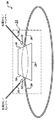
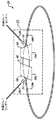
【解決手段】光源とセンサとの間の光の相互伝達のための光学カプラー装置22、および中空コアファイバー共振器106を有する共振器検出装置である。共振ファイバー端部の一方からの光は、最大結合効率が達成されるような適切なピッチおよび2つの傾斜表面を備える屈折率分布型(GRIN)レンズ102、104を介して、第2の共振器ファイバーの端部に結合される。傾斜表面は所望の結合度を達成するために反射率Rを有する適切な被覆剤でコートされる。第2の傾斜表面で反射された光は、(マイクロレンズ32のような)他のレンズで捕獲され、第3のファイバー領域(結合ポート)に結合される。GRINレンズおよびマイクロレンズの光学パラメータは、損失を最小化するように調整される。
【選択図】図3
Description
Claims (3)
- 共振器検出装置であって、前記装置は
フォトニックバンドギャップ共振器ファイバー(106)と、
第1の屈折率分布型(GRIN)レンズ(102)と、
第2の屈折率分布型(GRIN)レンズ(104)と、
少なくとも1つのマイクロレンズ(32)と、
少なくとも1つのソースファイバー(30)と、を有し、
前記第1のGRINレンズは、少なくとも1つの前記マイクロレンズおよび少なくとも1つの前記ソースファイバーから出てきた光を、前記共振器ファイバーの一方の端部に反射させるように、傾斜した表面を有し、
前記第2のGRINレンズは、前記共振器ファイバーの一方の端部から出てきた光の一部を、前記第1のGRINレンズを通過させ前記共振器ファイバーの他方の端部に受け入れられるように、且つ、前記共振器ファイバーの一方の端部から出てきた光の一部を、少なくとも1つの前記マイクロレンズを介して、少なくとも1つの前記ソースファイバー内に反射させるように、位置決めされる、共振器検出装置。 - 請求項2に記載の装置であって、前記GRINレンズの前記表面は誘電体で被覆され、前記フォトニックバンドギャップ共振器ファイバーは中空コアファイバーを含む、共振器検出装置。
- 共振器検出装置を製造する方法であって、前記方法は、
光源からの光を受け且つ光をセンサに伝達するように予め構成されたソースファイバーの端部をジグに配置するステップと、
前記ジグ上で、屈折率分布型(GRIN)レンズの位置として想定される位置にミラーを配置するステップと、
前記ジグ上で前記ソースファイバーと前記ミラーとの間にマイクロレンズを配置するステップと、
フォトニックバンドギャップ共振器ファイバーの一方の端部を、前記ジグ上に、前記ソースファイバーの配置される端部と前記マイクロレンズとから前記ミラーに対して、所定の角度関係で配置するステップと、
前記共振器ファイバーの外に、光信号を、前記ミラーに対して伝達し、前記マイクロレンズを介して前記ソースファイバーの端部内に伝達するステップと、
伝達された前記光信号をセンサで検出するステップと、
前記ジグ上で、前記ソースファイバーの端部、前記マイクロレンズ、および前記共振器ファイバーの少なくとも1つの位置を、検出された光信号に基づいて調整するステップと、
前記ミラーを取り除くステップと、
前記GRINレンズを挿入するステップと、を有する方法。
Applications Claiming Priority (2)
| Application Number | Priority Date | Filing Date | Title |
|---|---|---|---|
| US12/163,307 US7680372B2 (en) | 2008-06-27 | 2008-06-27 | Micro-optics photonic bandgap fiber coupler |
| US12/163,307 | 2008-06-27 |
Publications (2)
| Publication Number | Publication Date |
|---|---|
| JP2010009048A true JP2010009048A (ja) | 2010-01-14 |
| JP5522984B2 JP5522984B2 (ja) | 2014-06-18 |
Family
ID=41151753
Family Applications (1)
| Application Number | Title | Priority Date | Filing Date |
|---|---|---|---|
| JP2009151182A Active JP5522984B2 (ja) | 2008-06-27 | 2009-06-25 | マイクロ光学フォトニックバンドギャップファイバーカプラー |
Country Status (4)
| Country | Link |
|---|---|
| US (1) | US7680372B2 (ja) |
| EP (1) | EP2138876B1 (ja) |
| JP (1) | JP5522984B2 (ja) |
| AT (1) | ATE520048T1 (ja) |
Cited By (1)
| Publication number | Priority date | Publication date | Assignee | Title |
|---|---|---|---|---|
| US20130070252A1 (en) * | 2011-09-21 | 2013-03-21 | Honeywell International Inc. | Systems and methods for a hollow core resonant filter |
Families Citing this family (2)
| Publication number | Priority date | Publication date | Assignee | Title |
|---|---|---|---|---|
| CN102377098B (zh) * | 2010-08-10 | 2015-09-23 | Oe电波公司 | 激光器设备和用于锁定激光器的方法 |
| US20160011367A1 (en) * | 2014-07-08 | 2016-01-14 | Digital Signal Corporation | Apparatus and Method for Terminating an Array of Optical Fibers |
Citations (6)
| Publication number | Priority date | Publication date | Assignee | Title |
|---|---|---|---|---|
| JPS5581305A (en) * | 1978-12-15 | 1980-06-19 | Fujitsu Ltd | Optical fiber spherical lens aggregate |
| JPS5749913A (en) * | 1980-09-10 | 1982-03-24 | Mitsubishi Electric Corp | Optical branching and coupling circuit |
| JPS61226713A (ja) * | 1985-04-01 | 1986-10-08 | Hitachi Ltd | 光波長多重伝送用光モジユ−ル |
| JPH08248266A (ja) * | 1995-01-13 | 1996-09-27 | Seiko Giken:Kk | 光ファイバフェルールおよび前記光ファイバフェルールを用いた光カプラ |
| JP2004309851A (ja) * | 2003-04-08 | 2004-11-04 | Nippon Sheet Glass Co Ltd | 光分波合波器 |
| JP2008089594A (ja) * | 2006-09-29 | 2008-04-17 | Honeywell Internatl Inc | 光学式共振器ジャイロスコープ、および共振非対称誤差を低減するための方法 |
Family Cites Families (12)
| Publication number | Priority date | Publication date | Assignee | Title |
|---|---|---|---|---|
| US4775214A (en) * | 1983-12-21 | 1988-10-04 | Rosemount Inc. | Wavelength coded resonant optical sensor |
| US5436925A (en) | 1994-03-01 | 1995-07-25 | Hewlett-Packard Company | Colliding pulse mode-locked fiber ring laser using a semiconductor saturable absorber |
| EP0799432A4 (en) * | 1994-12-21 | 1999-03-24 | E Tek Dynamics Inc | INTEGRATABLE FIBER OPTIC COUPLING AND DEVICES AND SYSTEMS THEREOF |
| US5778014A (en) | 1996-12-23 | 1998-07-07 | Islam; Mohammed N. | Sagnac raman amplifiers and cascade lasers |
| US20030118073A1 (en) * | 2001-12-21 | 2003-06-26 | Fsona Communications Corporation | Compact optical amplifier, a system incorporating the same, and an optical amplification method |
| US20040061863A1 (en) | 2002-08-20 | 2004-04-01 | Digonnet Michel J.F. | Fiber optic sensors with reduced noise |
| US7180598B2 (en) | 2002-11-13 | 2007-02-20 | The Charles Stark Draper Laboratory, Inc. | Photonic crystal interferometric fiber optical gyroscope system |
| US7446880B2 (en) | 2005-04-06 | 2008-11-04 | President And Fellows Of Harvard College | Method and apparatus for measuring and monitoring optical properties based on a ring-resonator |
| US7327460B2 (en) | 2005-11-02 | 2008-02-05 | Honeywell International, Inc. | Transmission mode RFOG and method for detecting rotation with RFOG |
| US7463360B2 (en) | 2006-04-18 | 2008-12-09 | Honeywell International Inc. | Optical resonator gyro with integrated external cavity beam generator |
| JP2009543065A (ja) * | 2006-06-29 | 2009-12-03 | ザ ボード オブ トラスティーズ オブ レランド スタンフォード ジュニア ユニバーシティ | ブラッグファイバーを用いた光ファイバーセンサ |
| CN100547863C (zh) * | 2006-10-20 | 2009-10-07 | 香港理工大学 | 光纤气体激光器和具有该激光器的光纤型环形激光陀螺仪 |
-
2008
- 2008-06-27 US US12/163,307 patent/US7680372B2/en active Active
-
2009
- 2009-06-23 AT AT09163458T patent/ATE520048T1/de not_active IP Right Cessation
- 2009-06-23 EP EP09163458A patent/EP2138876B1/en active Active
- 2009-06-25 JP JP2009151182A patent/JP5522984B2/ja active Active
Patent Citations (6)
| Publication number | Priority date | Publication date | Assignee | Title |
|---|---|---|---|---|
| JPS5581305A (en) * | 1978-12-15 | 1980-06-19 | Fujitsu Ltd | Optical fiber spherical lens aggregate |
| JPS5749913A (en) * | 1980-09-10 | 1982-03-24 | Mitsubishi Electric Corp | Optical branching and coupling circuit |
| JPS61226713A (ja) * | 1985-04-01 | 1986-10-08 | Hitachi Ltd | 光波長多重伝送用光モジユ−ル |
| JPH08248266A (ja) * | 1995-01-13 | 1996-09-27 | Seiko Giken:Kk | 光ファイバフェルールおよび前記光ファイバフェルールを用いた光カプラ |
| JP2004309851A (ja) * | 2003-04-08 | 2004-11-04 | Nippon Sheet Glass Co Ltd | 光分波合波器 |
| JP2008089594A (ja) * | 2006-09-29 | 2008-04-17 | Honeywell Internatl Inc | 光学式共振器ジャイロスコープ、および共振非対称誤差を低減するための方法 |
Cited By (1)
| Publication number | Priority date | Publication date | Assignee | Title |
|---|---|---|---|---|
| US20130070252A1 (en) * | 2011-09-21 | 2013-03-21 | Honeywell International Inc. | Systems and methods for a hollow core resonant filter |
Also Published As
| Publication number | Publication date |
|---|---|
| EP2138876A1 (en) | 2009-12-30 |
| EP2138876B1 (en) | 2011-08-10 |
| US7680372B2 (en) | 2010-03-16 |
| US20090324169A1 (en) | 2009-12-31 |
| ATE520048T1 (de) | 2011-08-15 |
| JP5522984B2 (ja) | 2014-06-18 |
Similar Documents
| Publication | Publication Date | Title |
|---|---|---|
| US6934444B2 (en) | Beam shaping and practical methods of reducing loss associated with mating external sources and optics to thin silicon waveguides | |
| US6925233B2 (en) | Optical waveguide device manufacturing jig, method of manufacturing optical waveguide device by use of the same jig, and the same optical waveguide device | |
| US9435959B2 (en) | Coupling of fiber optics to planar grating couplers | |
| EP3803482B1 (en) | Device and method for coupling laser to a photonic integrated circuit | |
| US20030210874A1 (en) | Optical composite module, optical wavelength multiplexer, optical wavelength demultiplexer, and optical composite module manufacturing method | |
| US20090232450A1 (en) | Simple fiber optic cavity | |
| US20050069253A1 (en) | Device for introducing light into a waveguide, device for emitting light from a waveguide and method for manufacturing such devices | |
| JP2000180671A5 (ja) | ||
| JP2010282182A (ja) | 集積された光学レンズ回転ブロックを含むファイバー用コネクタモジュール及びトランシーバモジュールと光ファイバーとの間の光信号を結合する方法 | |
| KR20180019739A (ko) | 전달 섬유 어셈블리 및 광대역 소스 | |
| US7352924B2 (en) | Micro-optical device | |
| JP7188841B2 (ja) | シリコンレンズを有するマルチチャネルモードコンバータ | |
| JP2023529528A (ja) | 光結合および光学場のモード選択分離または重ね合わせ | |
| JP5522984B2 (ja) | マイクロ光学フォトニックバンドギャップファイバーカプラー | |
| JP7204556B2 (ja) | 光レセプタクル、光モジュールおよび光モジュールの製造方法 | |
| US6161965A (en) | Optical coupling circuit | |
| CN1771446A (zh) | 光束整形及降低将外部光源和光学器件连接至薄硅波导引起的损耗的实用方法 | |
| US20090060415A1 (en) | Fiber optic cavity | |
| JP4262692B2 (ja) | 光ファイバ反射モジュールの製造方法及びそれを用いた光フィルタモジュールの製造方法、波長多重通信用波長分離光モジュールの製造方法 | |
| FR2738921A1 (fr) | Coupleur optique capable d'empecher la sortie d'une lumiere parasite a une extremite d'incidence d'un isolateur optique | |
| KR100401805B1 (ko) | 가변형 광 필터 | |
| JP2011027900A (ja) | 光ファイバモジュール、光ファイバモジュールの製造方法 | |
| JPH10186165A (ja) | 光分波器または光分岐器 | |
| CN1324335C (zh) | 利用球端节精密调谐滤光器的方法和装置 | |
| CN116661067A (zh) | 一种光纤可调滤波器 |
Legal Events
| Date | Code | Title | Description |
|---|---|---|---|
| A621 | Written request for application examination |
Free format text: JAPANESE INTERMEDIATE CODE: A621 Effective date: 20120620 |
|
| A131 | Notification of reasons for refusal |
Free format text: JAPANESE INTERMEDIATE CODE: A131 Effective date: 20130821 |
|
| A977 | Report on retrieval |
Free format text: JAPANESE INTERMEDIATE CODE: A971007 Effective date: 20130821 |
|
| A977 | Report on retrieval |
Free format text: JAPANESE INTERMEDIATE CODE: A971007 Effective date: 20131001 |
|
| A521 | Written amendment |
Free format text: JAPANESE INTERMEDIATE CODE: A523 Effective date: 20131031 |
|
| TRDD | Decision of grant or rejection written | ||
| A01 | Written decision to grant a patent or to grant a registration (utility model) |
Free format text: JAPANESE INTERMEDIATE CODE: A01 Effective date: 20140310 |
|
| A61 | First payment of annual fees (during grant procedure) |
Free format text: JAPANESE INTERMEDIATE CODE: A61 Effective date: 20140408 |
|
| R150 | Certificate of patent or registration of utility model |
Ref document number: 5522984 Country of ref document: JP Free format text: JAPANESE INTERMEDIATE CODE: R150 |
|
| R250 | Receipt of annual fees |
Free format text: JAPANESE INTERMEDIATE CODE: R250 |
|
| R250 | Receipt of annual fees |
Free format text: JAPANESE INTERMEDIATE CODE: R250 |
|
| R250 | Receipt of annual fees |
Free format text: JAPANESE INTERMEDIATE CODE: R250 |
|
| R250 | Receipt of annual fees |
Free format text: JAPANESE INTERMEDIATE CODE: R250 |