JP2009279164A - Game machine - Google Patents
Game machine Download PDFInfo
- Publication number
- JP2009279164A JP2009279164A JP2008133904A JP2008133904A JP2009279164A JP 2009279164 A JP2009279164 A JP 2009279164A JP 2008133904 A JP2008133904 A JP 2008133904A JP 2008133904 A JP2008133904 A JP 2008133904A JP 2009279164 A JP2009279164 A JP 2009279164A
- Authority
- JP
- Japan
- Prior art keywords
- drive
- driving
- lamp
- control device
- executed
- Prior art date
- Legal status (The legal status is an assumption and is not a legal conclusion. Google has not performed a legal analysis and makes no representation as to the accuracy of the status listed.)
- Withdrawn
Links
Images


Abstract
Description
本発明は、遊技機に関するものである。 The present invention relates to a gaming machine.
パチンコ機等の遊技機には、表示画面を有する図柄表示装置を備えたものがある。例えば、パチンコ機における表示画面上では、遊技領域に備えられた作動口を遊技球が通過することを条件として図柄を変動表示し遊技の興趣を高める演出を行う、又は所定条件成立時に特定図柄を停止表示し、大当たり等の遊技者に有利な特別遊技状態の教示を行うものがある。遊技の興趣を高める演出として、例えば、大当たりと密接に関連し、遊技者に大当たりへの期待度を高めるようなリーチ演出がある。また、近年では、遊技の興趣を一層高めるべく、遊技回毎に変動表示される図柄に加えて演出用のキャラクタ等を表示しこのキャラクタを用いてリーチ演出を行う、或いは表示画面上に表示する図柄数を増加させる等の工夫が行われており、表示演出が多様化しつつある。 Some gaming machines such as pachinko machines are provided with a symbol display device having a display screen. For example, on the display screen of a pachinko machine, the design is variably displayed on the condition that the game ball passes through the operation port provided in the game area, and an effect that enhances the fun of the game is performed, or a specific design is displayed when a predetermined condition is established There are some which display a stop and teach a special gaming state advantageous to a player such as jackpot. As an effect that enhances the interest of the game, for example, there is a reach effect that is closely related to the jackpot and increases the expectation of the player on the jackpot. Further, in recent years, in order to further enhance the interest of the game, in addition to the symbols that are variably displayed for each game time, an effect character or the like is displayed and a reach effect is performed using this character, or displayed on the display screen. Various ideas such as increasing the number of symbols have been made, and display effects are diversifying.
また、遊技機によっては、駆動手段としてLED、ランプ、スピーカ等の駆動機器を有しており、それらの駆動機器はパチンコ機等に設けられた制御装置によって駆動される。駆動機器が制御されることによって遊技が進行したり、上記演出が行われたりしている(例えば特許文献1参照)。
近年、演出の多様化や、遊技の複雑化が進行しており、遊技機によっては多種多様な駆動機器が設けられている。しかしながら、それらの駆動機器が正常に動作しないとすると、遊技者の遊技への注目度が低下したり、遊技が正常に進行なかったりするおそれがある。 In recent years, the diversification of production and the complexity of games have progressed, and a variety of driving devices are provided depending on the gaming machine. However, if those drive devices do not operate normally, the player's attention to the game may be reduced, or the game may not proceed normally.
本発明は上記例示した事情等に鑑みてなされたものであり、複数の駆動手段を備えた遊技機において、各駆動手段が正常に動作するか否かの点検を良好に行うことが可能な遊技機を提供することを目的とするものである。 The present invention has been made in view of the above-mentioned circumstances and the like, and in a gaming machine having a plurality of driving means, it is possible to satisfactorily check whether or not each driving means operates normally. The purpose is to provide a machine.
以下、上記課題を解決するための手段について記載する。 Hereinafter, means for solving the above problems will be described.
請求項1記載の発明では、遊技機各部に電力を供給する電力供給手段と、前記電力供給手段から電力を受けて駆動される複数の駆動手段と、前記各駆動手段を駆動制御する駆動制御手段と、を備えた遊技機において、前記駆動制御手段は、前記各駆動手段を制御してその駆動が確認可能となる点検動作を前記各駆動手段について実行させるとともに、前記各駆動手段のうち第1駆動手段及び第2駆動手段の点検動作を期間の重複なく実行させる点検制御手段を有することを特徴とする。 According to the first aspect of the present invention, power supply means for supplying power to each part of the gaming machine, a plurality of drive means driven by receiving power from the power supply means, and drive control means for driving and controlling the drive means The drive control means controls each drive means to perform an inspection operation on the drive means so that the drive can be confirmed, and the first of the drive means. It has an inspection control means for executing the inspection operation of the driving means and the second driving means without overlapping the periods.
請求項2記載の発明では、遊技機各部に電力を供給する電力供給手段と、前記電力供給手段から電力を受けて駆動される複数の駆動手段と、前記各駆動手段を駆動制御する駆動制御手段と、を備えた遊技機において、前記駆動制御手段は、前記各駆動手段を制御してその駆動が確認可能となる点検動作を前記各駆動手段について実行させるとともに、前記各駆動手段のうち第1駆動手段の点検動作が終了した場合に第2駆動手段の点検動作を開始させる点検制御手段を有することを特徴とする。 According to a second aspect of the present invention, power supply means for supplying power to each part of the gaming machine, a plurality of drive means driven by receiving power from the power supply means, and drive control means for driving and controlling the drive means The drive control means controls each drive means to perform an inspection operation on the drive means so that the drive can be confirmed, and the first of the drive means. It has an inspection control means for starting the inspection operation of the second driving means when the inspection operation of the driving means is finished.
請求項3記載の発明では、請求項1又は2記載の発明において、前記点検制御手段は、前記第1駆動手段の点検動作を実行している期間の少なくとも一部において前記各駆動手段のうち第3駆動手段の点検動作を実行させることを特徴とする。 According to a third aspect of the present invention, in the first or second aspect of the present invention, the inspection control means is the first of the driving means in at least a part of a period during which the inspection operation of the first driving means is executed. The check operation of the three drive means is executed.
請求項4記載の発明では、遊技機各部に電力を供給する電力供給手段と、前記電力供給手段から電力を受けて駆動される複数の駆動手段と、前記各駆動手段を駆動制御する駆動制御手段と、を備えた遊技機において、前記駆動制御手段は、遊技の進行に伴い前記各駆動手段を駆動制御する遊技駆動制御手段と、前記各駆動手段を制御してその駆動が確認可能となる点検動作を前記各駆動手段について実行させるとともに、前記遊技駆動制御手段による駆動制御の場合に使用される最大電力を超えないよう各駆動手段の点検動作の期間をずらして実行させる点検制御手段と、を有することを特徴とする。 According to a fourth aspect of the present invention, power supply means for supplying power to each part of the gaming machine, a plurality of drive means driven by receiving power from the power supply means, and drive control means for driving and controlling the drive means In the gaming machine, the drive control means includes a game drive control means for driving and controlling each of the drive means as the game progresses, and an inspection for checking the drive by controlling each of the drive means. Check control means for causing the drive means to execute the operation and shifting the check operation period of each drive means so as not to exceed the maximum power used in the case of drive control by the game drive control means; It is characterized by having.
複数の駆動手段を備えた遊技機において、各駆動手段が正常に動作するか否かの点検を良好に行うことが可能となる。 In a gaming machine provided with a plurality of driving means, it is possible to satisfactorily check whether or not each driving means operates normally.
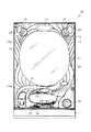
以下、遊技機の一種であるパチンコ遊技機(以下、「パチンコ機」という)の一実施の形態を、図面に基づいて詳細に説明する。図1はパチンコ機10の正面図、図2はパチンコ機10の主要な構成を展開して示す斜視図、図3はパチンコ機10の背面図である。なお、図2では便宜上パチンコ機10の遊技領域内の構成を省略している。
Hereinafter, an embodiment of a pachinko gaming machine (hereinafter referred to as “pachinko machine”), which is a type of gaming machine, will be described in detail with reference to the drawings. FIG. 1 is a front view of the
パチンコ機10は、当該パチンコ機10の外殻を形成する外枠11と、この外枠11に対して前方に回動可能に取り付けられた遊技機主部12とを有する。外枠11は木製又は合成樹脂製の板材を四辺に連結し構成されるものであって矩形枠状をなしている。パチンコ機10は、外枠11を島設備に取り付け固定することにより遊技ホールに設置される。
The
遊技機主部12は、ベース体としての本体枠13と、その本体枠13の前方に配置される前扉枠14と、本体枠13の後方に配置される裏パックユニット15とを備えている。遊技機主部12のうち本体枠13が外枠11に対して回動可能に支持されている。詳細には、正面視で左側を回動基端側とし右側を回動先端側として本体枠13が前方へ回動可能とされている。
The gaming machine
本体枠13には、前扉枠14と裏パックユニット15とがそれぞれ回動可能に支持されている。前扉枠14は、正面視で左側を回動基端側、右側を回動先端側として本体枠13に対して前方へ回動可能とされている。また、裏パックユニット15は、正面視で左側を回動基端側、右側を回動先端側として本体枠13に対して後方へ回動可能とされている。
A
前扉枠14は、本体枠13の前面側全体を覆うようにして設けられている。前扉枠14には、後述する遊技領域のほぼ全域を前方から視認することができるようにした窓部21が形成されている。窓部21は略楕円形状をなし、透明性を有するガラス22が嵌め込まれている。窓部21の周囲には、各種ランプ等の発光手段が設けられている。例えば、窓部21の周縁に沿ってLED等の発光手段を内蔵した環状電飾部23が設けられている。この環状電飾部23のうち窓部21における上下方向の中心よりも上方にあるものを上環状電飾部23a、下方にあるものを下環状電飾部23bとする。
The
環状電飾部23では、大当たり時や所定のリーチ時等における遊技状態の変化に応じて点灯や点滅が行われる。また、環状電飾部23の中央であってパチンコ機10の最上部には所定のエラー時に点灯するエラー表示ランプ部24が設けられ、さらにその左右側方には賞球払出中に点灯する賞球ランプ部25が設けられている。また、左右の賞球ランプ部25に近接した位置には、遊技状態に応じた効果音などが出力されるスピーカ部26が設けられている。このスピーカ部26のうち窓部21における左右方向の中心よりも左側にあるものを第1スピーカ部26a、右側にあるものを第2スピーカ部26bとする。
In the
前扉枠14における窓部21の下方には、手前側へ膨出することで上下2段に膨出部31,32(上側膨出部31、下側膨出部32)が設けられている。上側膨出部31には上方に開口した上皿33が設けられ、下側膨出部32には同じく上方に開口した下皿34が設けられている。上皿33は、後述する払出装置より払い出された遊技球を一旦貯留し、一列に整列させながら後述する遊技球発射装置側へ導くための機能を有する。また、下皿34は、上皿33内にて余剰となった遊技球を貯留する機能を有する。下側膨出部32の右方には、手前側へ突出するようにして遊技球発射ハンドル36が設けられている。遊技球発射ハンドル36が操作されることにより、後述する遊技球発射装置から遊技球が発射される。
Below the
前扉枠14の背面には、後述する払出装置により払い出される遊技球を上皿33と下皿34とに振り分けて流通させる通路形成ユニット37が取り付けられている。その他、前扉枠14の背面にはその回動先端側に、本体枠13に対する施錠機構を構成する鉤金具38が上下方向に複数設けられている。
A
本体枠13は、外形が外枠11とほぼ同一形状をなす樹脂ベース41を主体として構成されており、その回動先端側には、前扉枠14に設けられた鉤金具38を挿入するための挿入孔42が複数設けられている。鉤金具38が挿入孔42に挿入されることで、図示しない施錠装置が係止状態となり、前扉枠14が本体枠13に対して開放不能に施錠される。樹脂ベース41の右下隅部には、施錠装置の解錠操作を行うためのシリンダ錠43が設置されており、シリンダ錠43の鍵穴に差し込んだキーを右に回すと本体枠13に対する前扉枠14の施錠が解かれるようになっている。なお、シリンダ錠43の鍵穴に差し込んだキーを左に回すと外枠11に対する本体枠13の施錠が解かれるようになっている。
The
樹脂ベース41の中央部には略楕円形状の窓孔44が形成されている。樹脂ベース41には、窓孔44の下方に遊技球発射装置45が取り付けられている。遊技球発射装置45は、例えばソレノイド駆動式の発射機構を有しており、ソレノイドへの電気信号の入力により出力軸が伸縮方向に移動し、発射レール上の遊技球が遊技領域に向けて順次打ち出される。
A substantially
また、樹脂ベース41には遊技盤51が着脱可能に取り付けられている。遊技盤51は合板よりなり、遊技盤51の前面に形成された遊技領域が樹脂ベース41の窓孔44を通じて本体枠13の前面側に露出した状態となっている。
A
ここで、パチンコ機10の前方側における遊技盤51の構成を図4に基づいて説明する。遊技盤51には、ルータ加工が施されることによって前後方向に貫通する大小複数の開口部が形成されている。各開口部には一般入賞口52,可変入賞装置53,作動口54,スルーゲート55及び可変表示ユニット56等がそれぞれ設けられている。一般入賞口52、可変入賞装置53及び作動口54に遊技球が入ると、それが図示しない検知スイッチにより検知され、その検知結果に基づいて所定数の賞球の払い出しが実行される。その他に、遊技盤51の最下部にはアウト口57が設けられており、各種入賞口等に入らなかった遊技球はアウト口57を通って遊技領域から排出される。また、遊技盤51には、遊技球の落下方向を適宜分散、調整等するために多数の釘58が植設されているとともに、風車等の各種部材(役物)が配設されている。
Here, the configuration of the
可変表示ユニット56には、作動口54への入賞をトリガとして図柄を可変表示する図柄表示部61が設けられている。また、可変表示ユニット56には、図柄表示部61を囲むようにしてセンターフレーム62が配設されている。センターフレーム62の上部には、第1特定ランプ部63及び第2特定ランプ部64が設けられている。また、センターフレーム62の上部及び下部にはそれぞれ保留ランプ部65,66が設けられている。下側の保留ランプ部65は、図柄表示部61及び第1特定ランプ部63に対応しており、遊技球が作動口54を通過した回数は最大4回まで保留され保留ランプ部65の点灯によってその保留個数が表示されるようになっている。上側の保留ランプ部66は、第2特定ランプ部64に対応しており、遊技球がスルーゲート55を通過した回数は最大4回まで保留され保留ランプ部66の点灯によってその保留個数が表示されるようになっている。
The
第1特定ランプ部63では、作動口54への入賞をトリガとして所定の順序で発光色の切り替えが行われ、予め定められた色で停止表示された場合には大当たりが発生する。また、第2特定ランプ部64では、遊技球のスルーゲート55の通過をトリガとして所定の順序で発光色の切り替えが行われ、予め定められた色で停止表示された場合には作動口54に付随する電動役物が所定期間だけ開放状態となる。
In the first
可変入賞装置53は、通常は遊技球が入賞できない又は入賞し難い閉状態になっており、大当たりの際に遊技球が入賞しやすい所定の開放状態に切替えられるようになっている。可変入賞装置53の開放態様としては、所定期間(例えば30秒間)の経過又は所定個数(例えば10個)の入賞を1ラウンドとして、複数ラウンド(例えば15ラウンド)を上限として繰り返し開放されるものが一般的である。
The
遊技盤51には、内レール部67と外レール部68とが取り付けられており、これら各レール部67,68により誘導レールが構成され、遊技球発射装置45から発射された遊技球が遊技領域の上部に案内されるようになっている。
An
また、可変表示ユニット56における図柄表示部61の上方、かつ保留ランプ部66と第1特定ランプ部63とに挟まれた位置に可動役物69が設けられている。この可動役物69は可動することにより遊技結果を遊技者に教示するものである。可動役物69によってパチンコ機10の意匠性を高めるとともに遊技者の遊技への注目度を高めている。
A
次に、遊技盤51の背面における構成を図5を用いて説明する。
Next, the configuration on the back surface of the
遊技盤51に取り付けられる可変表示ユニット56には、その背後に音声ランプ制御装置70がその背後に設けられているとともに表示制御装置が搭載された制御ユニット71が取り付けられている。音声ランプ制御装置70は、後述する主制御装置からの指示に従い音声やランプ表示、及び表示制御装置の制御を司る音声ランプ制御基板を具備しており、音声ランプ制御基板が透明樹脂材料等よりなる基板ボックスに収容されて構成されている。
The
また、遊技盤51の背面において、可変表示ユニット56や音声ランプ制御装置70の下方には主制御装置72が搭載されている。主制御装置72は、遊技の主たる制御を司る機能(主制御回路)と、電源を監視する機能(停電監視回路)とを有する主制御基板を具備しており、当該主制御基板が透明樹脂材料等よりなる基板ボックスに収容されて構成されている。
A
次に、パチンコ機10の背面構成を図3を用いて説明する。
Next, the back configuration of the
図3において、裏パックユニット15は、透明性を有する合成樹脂により成形されてなる裏パック81を備えている。裏パック81は、樹脂ベース41とほぼ同じ外寸法を有しかつ略中央部に矩形状の開口部82aを有するベース部82と、パチンコ機10後方に突出するようにしてベース部82の開口部82aに設けられる保護カバー部83とを有する。保護カバー部83は左右側面及び上面が閉鎖されかつ下面のみが開放された略直方体形状をなし、少なくとも可変表示ユニット56を囲むのに十分な大きさを有する。また、保護カバー部83の背面側における略中央部には、順序教示手段としての動作チェックシール84が貼り付けられている。動作チェックシール84は、音声ランプ制御装置70におけるランプ部初期制御処理及びスピーカ部初期制御処理にて、遊技店等における管理者に使用されるものである。
In FIG. 3, the
ベース部82には、その右上部に外部端子板85が設けられている。外部端子板85には各種の出力端子が設けられており、これらの出力端子を通じて遊技ホール側の管理制御装置に対して各種信号が出力される。
The
ベース部82には、保護カバー部83を迂回するようにして払出機構部が配設されている。すなわち、裏パック81の最上部には上方に開口したタンク86が設けられており、タンク86には遊技ホールの島設備から供給される遊技球が逐次補給される。タンク86の下方には、下流側に向けて緩やかに傾斜するタンクレール87が連結され、タンクレール87の下流側には上下方向に延びるケースレール88が連結されている。ケースレール88の最下流部には払出装置89が設けられている。払出装置89より払い出された遊技球は、払出装置89の下流側に設けられた払出通路や遊技球分配部を経由して上皿33や下皿34に供給される。
The
ベース部82において開口部82aの下方には、払出制御装置91と電源・発射制御装置92とが搭載されている。これら各制御装置91,92は、払出制御装置91がパチンコ機10後方となるように前後に重ねて配置されている。払出制御装置91は、払出装置を制御する払出制御基板が基板ボックス内に収容されて構成されている。電源・発射制御装置92は、電源・発射制御基板が基板ボックス内に収容されて構成されており、当該基板により、各種制御装置等で要する所定の電源が生成されて出力され、さらに遊技者による遊技球発射ハンドル36の操作に伴う遊技球の打ち出しの制御が行われる。
In the
ここで、遊技盤51に取り付けられた可動役物69について図6,7を用いて説明する。図6は可動役物69の正面図であり、図7は可動役物69の分解斜視図である。
Here, the
可動役物69は、装飾部100と、装飾部100を回転させる駆動部101と、装飾部100及び駆動部101を収容するケース部102と、によって構成されている。
The
装飾部100は、キャラクタ(例えば、宇宙人)を模して形成されたキャラクタ本体103aと、装飾部100の下部を構成する下部材103bと、からなっている。キャラクタ本体103aと、下部材103bとを組合せることにより、パチンコ機10の意匠性を高める装飾体(例えば、宇宙人)として機能する。
The
駆動部101は、駆動モータ110と駆動モータ110を支持する支持部材111とからなっている。駆動モータ110の上部に設けられた回転軸112が装飾部100の下部に差込まれた状態にて回転することによって、装飾部100が回転する。
The
回転軸112には、回転軸112の回転に同期して回転する円盤状の回転盤113が設けられている。支持部材111には、回転盤113の回転位置を検出する位置検出センサ116が設けられている。
The rotating shaft 112 is provided with a disk-shaped rotating disk 113 that rotates in synchronization with the rotation of the rotating shaft 112. The
詳細な説明は省略するが、位置検出センサ116は光学式のフォトセンサであり、回転盤113には円盤が途切れたスリット部117が設けられている。スリット部117が位置検出センサ116を通過した場合には、スリット部117の通過を位置検出センサ116は検出できる。これにより、スリット部117の通過した位置を装飾部100の初期位置としてパチンコ機10にて認識することができる。換言すると、位置検出センサ116のスリット部117の検出により、装飾部100の回転位置の0点合わせをしているともいえる。すなわち、位置検出センサ116及びスリット部117が装飾部100の初期位置を検出する初期位置検出手段として機能する。また、本実施形態では、駆動モータ110の駆動により装飾部100が一定速度にて回転するようになっている。スリット部117の検出により装飾部100の初期位置を検出した場合、駆動モータ110の駆動期間により、装飾部100のどの位置にて回転しているかを認識できる。すなわち、回転盤113及び位置検出センサ116が装飾部100の位置検出手段として機能する。
Although the detailed description is omitted, the
ケース部102は、装飾部100及び駆動部101を収容するためのものであり、前面枠部材120と、可動役物69を可変表示ユニット56に装着するための取付部材121と、背面部材122とから形成されている。このケース部102は、背面部材122の前面側に前面枠部材120と取付部材121とがネジ等で固定され一体化されている。
The
前面枠部材120は、前後方向に厚みを有しており、前後に貫通した前面枠開口部125が設けられている。その開口部125から下方に向かって突出した板部126が前面枠部材120の下部に形成されている。板部126の後方には、下方向に向かって開放された前面枠下開口部127が形成されている。
The
取付部材121は板状に形成されており、その中央下部には前面枠部材120の開口部125に沿うようにして前後に貫通した取付開口部128が設けられている。取付開口部128は、下方に向かって開放されている。
The
背面部材122は、前後方向に厚みを有しており、後方側が閉鎖されており前方側が開放されている背面側開口部129が設けられている。また、背面部材122の底面130には、上下方向に開口した背面部材下開口部131が設けられている。
The
取付部材121を挟んで前面枠部材120と背面部材122とがケース部102として一体化されると、前方側が開口した開口空間が形成されるとともに、前面枠下開口部127と背面部材下開口部131とによってその開口空間から下方向に向かって開放された開口が形成される。そして、ケース部102の下方から装飾部100が取り付けられ、その開口空間内に装飾部100が収容されることにより、ケース部102の前方側から装飾部100が視認されることとなる。駆動部104は、前面枠部材120における板部126によって遮蔽され前方側から視認されないようになっている。そして、装飾部100がケース部102に収容された状態(可動役物69)にて可変表示ユニット56に固定される。
When the
次に、パチンコ機10の電気的構成について図8のブロック図を用いて説明する。なお、図8では、信号ラインを実線矢印で示し、電力の供給ラインを二重線矢印で示す。
Next, the electrical configuration of the
主制御装置72には、停電監視回路140とCPU141とが搭載されている。CPU141には、当該CPU141により実行される各種の制御プログラムや固定値データを記憶したROMと、そのROM内に記憶される制御プログラムの実行に際して各種のデータ等を一時的に記憶するためのメモリであるRAMと、割込回路やタイマ回路、データ入出力回路などの各種回路とが内蔵されている。CPU141には、アドレスバス及びデータバスで構成されるバスラインを介して入出力ポートが接続されている。
The
一方、主制御装置72におけるCPU141の出力側には、払出制御装置91におけるCPU142が接続されている。払出制御装置91におけるCPU142には、賞球コマンドなどといった各種コマンドが出力される。また、主制御装置72におけるCPU141から音声ランプ制御装置70におけるCPU143に対して各種コマンドなどが出力される。また、停電監視回路140は、主制御装置72におけるCPU143と電源・発射制御装置92とを中継している。
On the other hand, the
払出制御装置91は、払出装置89により賞球や貸し球の払出制御を行うものである。演算装置である払出制御装置91におけるCPU142は、そのCPU142により実行される制御プログラムや固定値データ等を記憶したROMと、ワークメモリ等として使用されるRAMとを備えている。
The
払出制御装置91におけるCPU142には、アドレスバス及びデータバスで構成されるバスラインを介して入出力ポートが接続されている。払出制御装置91の入力側には、主制御装置72におけるCPU141、電源・発射制御装置92が接続されている。また、払出制御装置91の出力側には、主制御装置72におけるCPU141が接続されている。
An input / output port is connected to the
音声ランプ制御装置70におけるCPU143は、各種ランプ部23〜25やスピーカ部26、及び表示制御装置145を制御するものである。音声ランプ制御装置70におけるCPU143は、そのCPU143により実行される制御プログラムや固定値データ等を記憶したROMと、ワークメモリ等として使用されるRAMとを備えている。
The
音声ランプ制御装置70におけるCPU143にはアドレスバス及びデータバスで構成されるバスラインを介して入出力ポートが接続されている。音声ランプ制御装置70におけるCPU143の入力側には主制御装置72におけるCPU141が接続されており、主制御装置72におけるCPU141から出力される各種コマンドに基づいて、各種ランプ部23〜25、スピーカ部26及び可動役物69を制御するとともに表示制御装置145にコマンドを出力する。表示制御装置145は、音声ランプ制御装置70から出力されたコマンドに基づいて図柄表示部61に設けられた図柄表示装置146を表示制御する。
An input / output port is connected to the
電源・発射制御装置92は発射制御を実行するCPU147を備えている。電源・発射制御装置92におけるCPU147は、遊技者による遊技球発射ハンドル36の操作に従って遊技球発射装置45の発射制御を担うものであり、遊技球発射装置45は所定の発射条件が整っている場合に駆動される。
The power supply /
また、電源・発射制御装置92は、音声ランプ制御装置70のCPU143に電力を供給するとともに、CPU143を介して各種ランプ部23〜25、スピーカ部26、可動役物69及び表示制御装置145に電力を供給する。そして、表示制御装置145から図柄表示装置146に対して電力が供給されることとなる。
Further, the power supply /
電源・発射制御装置92は、平滑化回路150と電圧変換回路151とを備えている。電源・発射制御装置92による電力変換(電圧変換)及び電力供給(電圧印加)について説明する。
The power source /
外部電源より電源・発射制御装置92における平滑化回路150にAC24Vの電圧が印加される。平滑化回路150は、24Vの交流電圧を全波整流するダイオードスタックと、ダイオードスタックにより全波整流された電圧をさらに平滑化して直流電圧を生成するコンデンサ及びダイオードと、を備えている。すなわち、平滑化回路150にて、パチンコ機10に印加された交流電圧24Vが直流電圧24Vに変換される(以下交流をAC、直流をDCという)。
A voltage of 24 V AC is applied from the external power source to the smoothing
平滑化回路150にて生成されたDC24Vが電圧変換回路151に印加される。電圧変換回路151は、電圧の大きさを変換するものであり、DC12,5Vの電圧に変換する。電圧変換回路151は、変換する電圧の大きさに対応したレギュレータを有している(図示略)。すなわち、本実施形態では、DC12,5Vの2種類の電圧の大きさに変換するため、2種類のレギュレータを有している。
The DC 24 V generated by the smoothing
DC24Vの電圧は、払出制御装置91を介して払出装置89に印加される。DC12Vの電圧は、停電監視回路140に対して印加される。また、DC12Vの電圧は、音声ランプ制御装置70を介して各種ランプ部23〜25、スピーカ部26及び可動役物69に対して印加されるとともに、音声ランプ制御装置70及び表示制御装置145を介して図柄表示装置146に印加される。DC5Vの電圧は、停電監視回路140を介して主制御装置72のCPU141、払出制御装置91のCPU142、音声ランプ制御装置70のCPU143及び音声ランプ制御装置70を介して表示制御装置145に対してそれぞれ印加される。DC5Vの電圧は、主に各制御装置のCPUによる制御を実行する上で使用される。
The voltage of DC 24 V is applied to the
なお、電源・発射制御装置92における電圧変換回路151よる電圧変換の順序を変更してもよく、例えば、AC24Vの電圧が印加された場合、AC5,12Vの電圧に電圧変換回路151にて変換し、電源・発射制御装置92にて印加されたAC24Vと、そのAC5,12Vの電圧を平滑化回路150にてDC5,12,24Vに変換してもよい。また、電源・発射制御装置92に供給される電圧の大きさや変換する電圧の大きさを変更してもよく、例えば、電源・発射制御装置92における平滑化回路150にAC100Vが印加される構成としてもよい。
Note that the order of voltage conversion by the
次に、図柄表示装置146の表示内容について、図9に基づいて説明する。
Next, display contents of the
図柄表示装置146には、左・中・右の3つの図柄列が設定されている。各図柄列は、例えば「0」〜「9」の数字を各々付した主図柄と、例えば菱形状の絵図柄からなる副図柄とにより構成されている。各主図柄及び副図柄がそれぞれ第1図柄を構成している。各図柄列では、数字の昇順又は降順に主図柄が配列されるとともに各主図柄の間に副図柄が配されている。すなわち、各図柄列には、10個の主図柄及び10個の副図柄の計20個の第1図柄が備えられている。そして、図柄表示装置146には、各図柄列毎に20個の第1図柄が周期性をもって上から下へとスクロールするように変動表示されるようになっている。図柄表示装置146には、各図柄列毎に上・中・下の3段の第1図柄が表示されるようになっている。従って、図柄表示装置146には、3段×3列の計9個の第1図柄が表示される。また、図柄表示装置146には、5つの有効ライン、すなわち上ラインL1、中ラインL2、下ラインL3、右上がりラインL4、左上がりラインL5が設定されている。そして、左図柄列→右図柄列→中図柄列の順に変動表示が停止し、その停止時にいずれかの有効ライン上に大当たり図柄の組合せ(本実施の形態では、同一の主図柄の組合せ)で揃えば大当たりとして大当たり動画が表示されるようになっている。
In the
本実施の形態では、主制御装置72内のCPU141は、遊技に際し各種カウンタ情報を用いて、大当たり抽選、第1特定ランプ部63の発光色の設定や、図柄表示装置146の図柄表示の設定などを行うこととしており、具体的には、図10に示すように、大当たりの抽選に使用する大当たり乱数カウンタC1と、特定大当たりや非特定大当たり等の大当たり種別を判定する際に使用する大当たり種別カウンタC2と、図柄表示装置146が外れ変動する際のリーチ抽選に使用するリーチ乱数カウンタC3と、大当たり乱数カウンタC1の初期値設定に使用する乱数初期値カウンタCINIと、図柄表示装置146の変動パターン選択に使用する第1変動種別カウンタCS1と、第1特定ランプ部63に表示される色の切り替えを行う期間を決定する第2変動種別カウンタCS2と、左列、中列及び右列の各外れ図柄の設定に使用する左・中・右の各外れ図柄カウンタCL,CM,CRとを用いることとしている。
In the present embodiment, the CPU 141 in the
このうち、カウンタC1〜C3,CINI,CS1,CS2は、その更新の都度前回値に1が加算され、最大値に達した後0に戻るループカウンタとなっている。また、外れ図柄カウンタCL,CM,CRは、主制御装置72のCPU141内のRレジスタ(リフレッシュレジスタ)を用いてレジスタ値が加算され、結果的に数値がランダムに変化する構成となっている。各カウンタは所定期間毎で更新され、その更新値が主制御装置72のRAMの所定領域に設定されたカウンタ用エリアに適宜格納される。主制御装置72のRAMには、1つの実行エリアと4つの保留エリア(保留第1〜第4エリア)とからなる保留球格納エリアが設けられており、これらの各エリアには、作動口54への遊技球の入賞履歴に合わせて、大当たり乱数カウンタC1、大当たり種別カウンタC2及びリーチ乱数カウンタC3の各値が時系列的に格納されるようになっている。
Among these, the counters C1 to C3, CINI, CS1, and CS2 are loop counters that each add 1 to the previous value and return to 0 after reaching the maximum value. Further, the out symbol counters CL, CM, CR are configured such that register values are added using an R register (refresh register) in the CPU 141 of the
各カウンタについて詳しくは、大当たり乱数カウンタC1は、例えば0〜676の範囲内で順に1ずつ加算され、最大値(つまり676)に達した後0に戻る構成となっている。特に大当たり乱数カウンタC1が1周した場合、その時点の乱数初期値カウンタCINIの値が当該大当たり乱数カウンタC1の初期値として読み込まれる。なお、乱数初期値カウンタCINIは、大当たり乱数カウンタC1と同様のループカウンタである(値=0〜676)。大当たり乱数カウンタC1は定期的に(本実施の形態ではタイマ割込み毎に1回)更新され、遊技球が作動口54に入賞したタイミングで主制御装置72のRAMの保留球格納エリアに格納される。
For details of each counter, the jackpot random number counter C1 is configured such that, for example, 1 is sequentially added within a range of 0 to 676, and after reaching the maximum value (that is, 676), it returns to 0. In particular, when the jackpot random number counter C1 makes one round, the value of the random number initial value counter CINI at that time is read as the initial value of the jackpot random number counter C1. The random number initial value counter CINI is a loop counter similar to the big hit random number counter C1 (value = 0 to 676). The jackpot random number counter C1 is updated periodically (once every timer interruption in the present embodiment) and stored in the reserved ball storage area of the RAM of the
大当たり種別カウンタC2は、0〜49の範囲内で順に1ずつ加算され、最大値(つまり49)に達した後0に戻る構成となっている。そして、本実施の形態では、大当たり種別カウンタC2によって、大当たりが終了した後に、高確率状態とするか通常状態とするかを決定することとしている。大当たり種別カウンタC2は定期的に(本実施の形態ではタイマ割込み毎に1回)更新され、遊技球が作動口54に入賞したタイミングで主制御装置72のRAMの保留球格納エリアに格納される。
The jackpot type counter C2 is incremented by 1 within a range of 0 to 49, and reaches a maximum value (that is, 49) and then returns to 0. In the present embodiment, the jackpot type counter C2 determines whether to enter a high probability state or a normal state after the jackpot is over. The jackpot type counter C2 is updated periodically (once every timer interruption in this embodiment) and stored in the reserved ball storage area of the RAM of the
リーチ乱数カウンタC3は、例えば0〜238の範囲内で順に1ずつ加算され、最大値(つまり238)に達した後0に戻る構成となっている。本実施の形態では、リーチ乱数カウンタC3によって、リーチ発生した後最終停止図柄がリーチ図柄の前後に1つだけずれて停止する「前後外れリーチ」と、同じくリーチ発生した後最終停止図柄がリーチ図柄の前後以外で停止する「前後外れ以外リーチ」と、リーチ発生しない「完全外れ」とを抽選することとしている。リーチ乱数カウンタC3は定期的に(本実施の形態ではタイマ割込み毎に1回)更新され、遊技球が作動口54に入賞したタイミングで主制御装置72のRAMの保留球格納エリアに格納される。
For example, the reach random number counter C3 is incremented one by one within a range of 0 to 238, for example, and reaches a maximum value (that is, 238) and then returns to 0. In the present embodiment, the reach random number counter C3 causes the final stop symbol after the occurrence of reach to stop by shifting the last stop symbol by one before and after the reach symbol, and the final stop symbol after the occurrence of reach also reaches the reach symbol. “Reach other than front / rear out” and stop “complete out” that does not occur reach. The reach random number counter C3 is updated periodically (once every timer interruption in the present embodiment), and stored in the reserved ball storage area of the RAM of the
第1変動種別カウンタCS1は、例えば0〜198の範囲内で順に1ずつ加算され、最大値(つまり198)に達した後0に戻る構成となっており、第2変動種別カウンタCS2は、例えば0〜240の範囲内で順に1ずつ加算され、最大値(つまり240)に達した後0に戻る構成となっている。第1変動種別カウンタCS1によって、いわゆるノーマルリーチ、スーパーリーチ、プレミアムリーチ等、第1図柄のリーチ種別やその他大まかな図柄変動態様といった図柄表示装置146の表示態様が決定され、第2変動種別カウンタCS2によって、第1特定ランプ部63に表示される色の切り替えを行う期間としての切替表示期間が決定される。また、この切替表示期間は、図柄表示装置146の図柄の変動期間に相当する。したがって、当該第2変動種別カウンタCS2によって、図柄表示装置146においてリーチが発生した後に最終停止図柄(本実施の形態では中図柄)が停止するまでの経過期間(言い換えれば、変動図柄数)などより細かな図柄変動態様も決定されることとなる。つまり、図柄表示装置146に関しては、これらの両変動種別カウンタCS1,CS2を組み合わせることで、変動パターンの多種多様化を容易に実現できる。両変動種別カウンタCS1,CS2は、後述する通常処理が1回実行される毎に1回更新され、当該通常処理内の残余期間内でも繰り返し更新される。そして、第1特定ランプ部63に表示される色の切り替え開始時及び図柄表示装置146による第1図柄の変動開始時における変動パターン決定に際して両変動種別カウンタCS1,CS2のエリア値が取得される。
The first variation type counter CS1 is, for example, incremented by 1 within a range of 0 to 198, and reaches a maximum value (that is, 198) and then returns to 0. The second variation type counter CS2 includes, for example, Within the range of 0 to 240, 1 is added in order, and after reaching the maximum value (that is, 240), it returns to 0. The first variation type counter CS1 determines the display mode of the
左・中・右の各外れ図柄カウンタCL,CM,CRは、大当たり抽選が外れとなった時に左列第1図柄、中列第1図柄、右列第1図柄の外れ停止図柄を決定するためのものであり、各列では主図柄及び副図柄の合わせて20の第1図柄の何れかが表示されることから、各々に20個(0〜19)のカウンタ値が用意されている。外れ図柄カウンタCLにより左図柄列の上・中・下段の各図柄が決定され、外れ図柄カウンタCMにより中図柄列の上・中・下段の各図柄が決定され、外れ図柄カウンタCRにより右図柄列の上・中・下段の各図柄が決定される。 The left, middle and right off symbol counters CL, CM, and CR determine the stop symbol of the left row 1st symbol, the middle row 1st symbol, and the right row 1st symbol when the big hit lottery is missed. In each column, any one of the 20 first symbols in total including the main symbol and the sub symbol is displayed, so 20 counter values (0 to 19) are prepared for each. The left, upper, middle, and lower symbols are determined by the out symbol counter CL, the upper, middle, and lower symbols are determined by the out symbol counter CM, and the right symbol column is determined by the out symbol counter CR. The upper, middle and lower symbols are determined.
本実施の形態では、主制御装置72のCPU141に内蔵のRレジスタの数値を用いることにより各カウンタCL,CM,CRの値をランダムに更新する構成としている。すなわち、各外れ図柄カウンタCL,CM,CRの更新時には、前回値にRレジスタの下位3ビットの値が加算され、その加算結果が最大値を超えた場合に20減算されて今回値が決定される。各外れ図柄カウンタCL,CM,CRは更新時期が重ならないようにして通常処理内で更新され、それら外れ図柄カウンタCL,CM,CRの組合せが、RAMの前後外れリーチ図柄エリア、前後外れ以外リーチ図柄エリア及び完全外れ図柄エリアの何れかに格納される。そして、第1図柄の変動開始時における変動パターン決定に際し、リーチ乱数カウンタC3の値に応じて前後外れリーチ図柄エリア、前後外れ以外リーチ図柄エリア及び完全外れ図柄エリアの何れかのエリア値が取得される。
In the present embodiment, the value of each counter CL, CM, CR is updated at random by using the value of the R register built in the CPU 141 of the
なお、図示は省略するが、第2特定ランプ部64の抽選には第2特定ランプ乱数カウンタが用いられる。第2図柄乱数カウンタは、例えば0〜250の範囲内で順に1ずつ加算され、最大値(つまり250)に達した後0に戻るループカウンタとして構成されている。第2特定ランプ乱数カウンタは定期的に(本実施の形態ではタイマ割込み毎に1回)更新され、遊技球がスルーゲート55を通過したことが検知された時に取得される。
Although illustration is omitted, a second specific lamp random number counter is used for the lottery of the second
次に、主制御装置72のCPU141により実行される各制御処理について説明する。
Next, each control process executed by the CPU 141 of the
先ず、タイマ割込み処理について図11のフローチャートを用いて説明する。 First, timer interrupt processing will be described with reference to the flowchart of FIG.
先ずステップS101では、読み込み処理を実行する。読み込み処理では、各入賞口に設けられた入賞口センサ、スルーゲート55に設けられたゲートセンサ等といった遊技球の入賞に関するセンサからの信号読み込み処理を実行する。
First, in step S101, a reading process is executed. In the reading process, a signal reading process from a sensor relating to winning of a game ball, such as a winning hole sensor provided in each winning hole, a gate sensor provided in the through
ステップS101では、各種入賞スイッチの読み込み処理を実行する。すなわち、主制御装置72に接続されている各種スイッチの状態を読み込むとともに、当該スイッチの状態を判定して検出情報(入賞検知情報)を保存する。
In step S101, various winning switch reading processes are executed. That is, the state of various switches connected to the
その後、ステップS102では、乱数初期値カウンタCINIの更新を実行する。具体的には、乱数初期値カウンタCINIを1加算するとともに、そのカウンタ値が最大値(本実施の形態では676)に達した際0にクリアする。そして、乱数初期値カウンタCINIの更新値を、主制御装置72のRAMの該当するエリアに格納する。続くステップS103では、大当たり乱数カウンタC1、大当たり種別カウンタC2及びリーチ乱数カウンタC3の更新を実行する。具体的には、大当たり乱数カウンタC1、大当たり種別カウンタC2及びリーチ乱数カウンタC3をそれぞれ1加算するとともに、それらのカウンタ値が最大値(本実施の形態ではそれぞれ、676,49,238)に達した際それぞれ0にクリアする。そして、各カウンタC1〜C3の更新値を、主制御装置72のRAMの該当するエリアに格納する。その後、ステップS104にて始動入賞処理を実行する。
Thereafter, in step S102, the random number initial value counter CINI is updated. Specifically, the random number initial value counter CINI is incremented by 1 and cleared to 0 when the counter value reaches the maximum value (676 in the present embodiment). Then, the update value of the random number initial value counter CINI is stored in the corresponding area of the RAM of the
始動入賞処理では、図12のフローチャートに示すように、先ずステップS201にて、主制御装置72のRAMの作動口フラグ格納エリアに作動口フラグが格納されているか否かを判定することにより、遊技球が作動口54に入賞(始動入賞)したか否かを判定する。遊技球が作動口54に入賞したと判定すると、続くステップS202において、第1特定ランプ部63及び図柄表示装置146の作動保留球数Nが上限値(本実施の形態では4)未満であるか否かを判定する。作動口54への入賞があり、且つ作動保留球数N<4であることを条件にステップS203に進み、作動保留球数Nを1加算する。なお、ステップS203の処理後に作動口フラグを消去する。続くステップS204では、前記ステップS203で更新した大当たり乱数カウンタC1、大当たり種別カウンタC2及びリーチ乱数カウンタC3の各値を、主制御装置72におけるRAMの保留球格納エリアの空き記憶エリアのうち最初のエリアに格納する。そして、始動入賞処理の後、主制御装置72のCPU141は本タイマ割込み処理を終了する。
In the start winning process, as shown in the flowchart of FIG. 12, first, in step S201, it is determined whether or not the operating port flag is stored in the operating port flag storage area of the RAM of the
図13は、NMI割込み処理を示すフローチャートであり、本処理は、主制御装置72のCPU141により停電の発生等によるパチンコ機10の電源遮断時に実行される。このNMI割込みにより、電源遮断時の主制御装置72の状態がRAMのバックアップエリアに記憶される。すなわち、停電の発生等によりパチンコ機10の電源が遮断されると、停電信号が停電監視回路140から主制御装置72内のCPU141のNMI端子に出力され、CPU141は実行中の制御を中断してNMI割込み処理を開始する。図13のNMI割込み処理プログラムは、主制御装置72のROMに記憶されている。停電信号が出力された後所定期間は、主制御装置72の処理が実行可能となるように電源・発射制御装置92から電源供給がなされており、この所定期間内にNMI割込み処理が実行される。
FIG. 13 is a flowchart showing the NMI interrupt process. This process is executed by the CPU 141 of the
NMI割込み処理において、ステップS301では使用レジスタを主制御装置72のRAMのバックアップエリアに退避し、続くステップS302ではスタックポインタの値を同バックアップエリアに記憶する。さらに、ステップS303では電源遮断の発生情報をバックアップエリアに設定し、ステップS304では電源が遮断されたことを示す電源遮断通知コマンドを他の制御装置に対して送信する。ステップS305では主制御装置72のRAM判定値を算出し、バックアップエリアに保存する。RAM判定値は、例えば、主制御装置72のRAMの作業領域アドレスにおけるチェックサム値である。ステップS306では、RAMアクセスを禁止する。その後は、電源が完全に遮断して処理が実行できなくなるのに備え、無限ループに入る。
In the NMI interrupt processing, in step S301, the used register is saved in the RAM backup area of the
なお、上記のNMI割込み処理は払出制御装置91でも同様に実行され、かかるNMI割込みにより、停電の発生等による電源遮断時の払出制御装置91の状態が払出制御装置91のRAMのバックアップエリアに記憶される。停電信号が出力された後所定期間は、払出制御装置91の処理が実行可能となるように電源・発射制御装置92から電源供給がなされるのも同様である。すなわち、停電の発生等によりパチンコ機10の電源が遮断されると、停電信号が停電監視回路140から払出制御装置91内のCPU142のNMI端子に出力され、当該CPU142は実行中の制御を中断して図13のNMI割込み処理を開始する。その内容はステップS304の電源遮断通知コマンドの送信を行わない点を除き上記説明と同様である。
The above NMI interrupt processing is executed in the same manner in the
図14は、主制御装置72内のCPU141により実行されるメイン処理の一例を示すフローチャートであり、このメイン処理は電源投入時のリセットに伴い起動される。
FIG. 14 is a flowchart showing an example of a main process executed by the CPU 141 in the
メイン処理において、ステップS401では、電源投入に伴う初期設定処理を実行する。具体的には、スタックポインタに予め決められた所定値を設定するとともに、サブ側の制御装置(音声ランプ制御装置70、払出制御装置91等)が動作可能な状態になるのを待つために例えば1秒程度、ウェイト処理を実行する。ステップS402では、払出制御装置91に対して払出許可コマンドを送信し、続くステップS403では、RAMアクセスを許可する。
In the main process, in step S401, an initial setting process associated with power-on is executed. Specifically, in order to set a predetermined value in the stack pointer and wait for the sub-side control devices (such as the sound
その後、主制御装置72のCPU141内のRAMに関してデータバックアップの処理を実行する。つまり、ステップS404では電源装置に設けたRAM消去スイッチが押されているか否かを判別し、続くステップS405では主制御装置72のRAMのバックアップエリアに電源遮断の発生情報が設定されているか否かを判別する。また、ステップS406ではRAM判定値を算出し、続くステップS407では、そのRAM判定値が電源遮断時に保存したRAM判定値と一致するか否か、すなわちバックアップの有効性を判別する。RAM判定値は、例えばRAMの作業領域アドレスにおけるチェックサム値である。なお、RAMの所定のエリアに書き込まれたキーワードが正しく保存されているか否かによりバックアップの有効性を判断することも可能である。
Thereafter, data backup processing is executed for the RAM in the CPU 141 of the
本パチンコ機10では、例えばホールの営業開始時など、電源投入時にRAMデータを初期化する場合にはRAM消去スイッチを押しながら電源が投入される。従って、RAM消去スイッチが押されていれば、RAMの初期化処理(ステップS414〜S416)に移行する。また、電源遮断の発生情報が設定されていない場合や、RAM判定値(チェックサム値等)によりバックアップの異常が確認された場合も同様に主制御装置72のRAMの初期化処理(ステップS414〜S416)に移行する。つまり、ステップS414では主制御装置72のRAMの使用領域を0にクリアし、続くステップS415では当該RAMの初期化処理を実行する。また、ステップS416では割込み許可を設定し、後述する通常処理に移行する。
In the
一方、RAM消去スイッチが押されていない場合には、電源遮断の発生情報が設定されていること、及びRAM判定値(チェックサム値等)が正常であることを条件に、復電時の処理(電源遮断復旧時の処理)を実行する。つまり、ステップS408では電源遮断前のスタックポインタを復帰させ、ステップS409では電源遮断の発生情報をクリアする。ステップS410ではサブ側の制御装置を電源遮断時の遊技状態に復帰させるためのコマンドを送信し、ステップS411では使用レジスタを主制御装置72のRAMのバックアップエリアから復帰させる。また、ステップS412,S413では、割込み許可/不許可を電源遮断前の状態に復帰させた後、電源遮断前の番地へ戻る。
On the other hand, if the RAM erasure switch is not pressed, processing at the time of power recovery is performed on condition that the information on occurrence of power shutdown is set and the RAM judgment value (checksum value etc.) is normal. (Processing when power is restored) is executed. That is, in step S408, the stack pointer prior to power shutdown is restored, and in step S409, information on occurrence of power shutdown is cleared. In step S410, a command for returning the sub-side control device to the gaming state at the time of power-off is transmitted, and in step S411, the used register is returned from the RAM backup area of the
次に、通常処理の流れを図15のフローチャートを参照しながら説明する。この通常処理では遊技の主要な処理が実行される。その概要として、ステップS501〜S507の処理が4msec周期の定期処理として実行され、その残余期間でステップS509,S510のカウンタ更新処理が実行される構成となっている。 Next, the flow of normal processing will be described with reference to the flowchart of FIG. In this normal process, the main process of the game is executed. As an outline, the processing of steps S501 to S507 is executed as a periodic processing with a period of 4 msec, and the counter update processing of steps S509 and S510 is executed in the remaining period.
通常処理において、ステップS501では、前回の処理で更新されたコマンド等の出力データをサブ側の各制御装置に送信する。具体的には、入賞検知情報の有無を判別し、入賞検知情報があれば払出制御装置91に対して獲得遊技球数に対応する賞球払出コマンドを送信する。また、図柄表示装置146による図柄の変動表示に際しては停止図柄コマンド、変動パターンコマンド、変動終了コマンド等の表示コマンドを表示制御装置145に対して送信する。さらに、大当たり状態への移行に際しては状態移行コマンドを、可変入賞装置53の開閉に際しては開放コマンドや閉鎖コマンドを表示制御装置145に対して送信する。
In normal processing, in step S501, output data such as a command updated in the previous processing is transmitted to each control device on the sub side. Specifically, the presence / absence of winning detection information is determined, and if there is winning detection information, a winning ball payout command corresponding to the number of acquired game balls is transmitted to the
次に、ステップS502では、変動種別カウンタCS1,CS2の更新を実行する。具体的には、変動種別カウンタCS1,CS2を1インクリメントするとともに、カウンタ値が最大値(本実施の形態では198)に達した際にはカウンタ値を0にクリアする。そして、変動種別カウンタCS1,CS2の更新値を、主制御装置72のRAMの該当するバッファ領域に格納する。
Next, in step S502, update of the variation type counters CS1 and CS2 is executed. Specifically, the variation type counters CS1 and CS2 are incremented by 1, and the counter value is cleared to 0 when the counter value reaches the maximum value (198 in this embodiment). Then, the update values of the variation type counters CS1 and CS2 are stored in the corresponding buffer area of the RAM of the
続くステップS503では、左図柄列、中図柄列及び右図柄列の各外れ図柄カウンタCL,CM,CRの更新を実行する。 In the subsequent step S503, updating of each outlier symbol counter CL, CM, CR of the left symbol row, the middle symbol row, and the right symbol row is executed.
外れ図柄カウンタCL,CM,CRの更新処理では、左・中・右図柄列のいずれかの更新時期か否かを判定し、更新時期となった図柄列の外れ図柄カウンタCL,CM,CRを更新する。各外れ図柄カウンタCL,CM,CRは、重複することなく1回の通常処理で1つずつ順に更新され、通常処理を3回実行する毎に外れ図柄カウンタCL,CM,CRの1セット分が更新されるようになっている。そして、更新した外れ図柄カウンタCL,CM,CRの組合せが、前後外れリーチとなる外れリーチ図柄の組合せである場合、前後外れ以外リーチ図柄の組合せである場合、リーチとならない完全外れ図柄の組合せである場合には、その組合せがそれぞれに対応したエリア内に格納される。なお、更新した外れ図柄カウンタCL,CM,CRの組合せが大当たり図柄の組合せである場合には、そのまま更新処理を終了する。 In the update process of the out symbol counters CL, CM, CR, it is determined whether or not it is the update time of any of the left, middle, and right symbol sequences, and the out symbol counter CL, CM, CR of the symbol sequence that has reached the update time is determined. Update. Each out symbol counter CL, CM, CR is updated one by one in one normal process without duplication, and every time the normal processing is executed three times, one set of out symbol counters CL, CM, CR is obtained. It has been updated. And, when the combination of the updated out symbol counters CL, CM, CR is a combination of outreach symbols that are front / rear out of reach, a combination of reach symbols other than front / rear out of reach, a combination of completely out symbols that do not become reach In some cases, the combination is stored in the corresponding area. If the combination of the updated off symbol counters CL, CM, and CR is a combination of jackpot symbols, the update process is terminated as it is.
外れ図柄カウンタCL,CM,CRの更新処理の後、図15のステップS504では、払出制御装置91より受信した賞球計数信号や払出異常信号を読み込む。その後、ステップS505では、第1特定ランプ部63に表示される色の切り替えを行うための第1特定ランプ部制御処理を実行する。この第1特定ランプ部制御処理では、大当たり判定や図柄表示装置146による図柄の変動表示の設定、第1特定ランプ部63に配設されたLEDのスイッチのオンオフ制御などを行う。但し、第1特定ランプ部制御処理の詳細は後述する。
After update processing of the off symbol counters CL, CM, CR, in step S504 in FIG. 15, the prize ball counting signal and the payout abnormality signal received from the
次に、前記ステップS505の第1特定ランプ部制御処理について図16を用いて説明する。 Next, the first specific lamp unit control process in step S505 will be described with reference to FIG.
第1特定ランプ部制御処理において、ステップS601では、今現在の遊技状態が大当たり状態であるか否かを判別し、大当たり状態である場合にはそのまま本処理を終了する。大当たり状態でない場合には、ステップS602にて第1特定ランプ部63が切り替え表示中であるか否かを判別する。第1特定ランプ部63が切り替え表示中でない場合にはステップS603に進み、第1特定ランプ部63及び図柄表示装置146の作動保留球数Nが0よりも大きいか否かを判別する。そして、作動保留球数Nが0である場合には、そのまま本処理を終了する。
In the first specific lamp unit control process, in step S601, it is determined whether or not the current gaming state is a jackpot state, and if it is a jackpot state, the process is terminated as it is. If it is not a big hit state, it is determined in step S602 whether or not the first
作動保留球数N>0であれば、ステップS604に進む。ステップS604では、作動保留球数Nを1減算する。ステップS605では、保留球格納エリアに格納されたデータをシフトさせる処理を実行する。このデータシフト処理は、保留球格納エリアの保留第1〜第4エリアに格納されているデータを実行エリア側に順にシフトさせる処理であって、保留第1エリア→実行エリア、保留第2エリア→保留第1エリア、保留第3エリア→保留第2エリア、保留第4エリア→保留第3エリアといった具合に各エリア内のデータがシフトされる。 If the number of active balls N> 0, the process proceeds to step S604. In step S604, 1 is subtracted from the number N of active suspension balls. In step S605, a process for shifting the data stored in the reserved ball storage area is executed. This data shift process is a process of sequentially shifting the data stored in the reserved first to fourth areas of the reserved ball storage area to the execution area side, and the reserved first area → execution area, reserved second area → The data in each area is shifted such as the first hold area, the third hold area → the second hold area, the fourth hold area → the third hold area.
ステップS606では、第1特定ランプ部63に表示される色の切り替えを開始する切り替え開始処理を実行する。具体的には、表示される色の切り替え時期を判断するためのタイマをリセットし、さらに第1特定ランプ部63に配設されたLEDのスイッチを全てオフ制御した上で、赤色光源のスイッチをオン制御する。これにより、第1特定ランプ部63には、赤色が表示される。ちなみに、大当たり状態の終了後以外であれば、切り替え表示開始前は青色光源のスイッチがオンとなっており、大当たり状態の終了後であれば、赤色光源又は緑色光源のスイッチがオンとなっている。
In step S606, a switching start process for starting switching of the color displayed on the first
その後、ステップS607では変動パターン決定処理を実行する。この変動パターンコマンド決定処理にて図柄の変動表示が開始されてからその図柄の変動表示が終了するまでの期間が決定される。パチンコ機10では、図柄の変動表示が開始されてから終了するまでを1遊技回としており、変動パターンコマンド決定処理では、1遊技回の期間を決定しているともいえる。なお、変動パターンコマンドは、その遊技回にて参照された各カウンタC1〜C3及び変動種別カウンタCS1,CS2から決定されるものであり、この変動パターン決定処理にて決定された期間に亘りステップS606における切り替え処理が実行されることとなる。なお、各カウンタC1〜C3、変動種別カウンタCSの値と変動パターンとの関係は、図示しないテーブルにより予め規定されている。
Thereafter, in step S607, a variation pattern determination process is executed. In this variation pattern command determination process, the period from the start of the symbol variation display to the termination of the symbol variation display is determined. In the
この変動パターンコマンドが音声ランプ制御装置70に出力され、当該コマンドが音声ランプ制御装置70から表示制御装置145に出力されることによって表示制御装置145は1遊技回の期間を把握することができる。本変動パターン決定処理を実行したら第1特定ランプ部制御処理を終了する。ここで決定された変動パターンコマンドは上述した通常処理におけるステップS501の外部出力処理にて音声ランプ制御装置70に出力される。この際、変動パターンコマンドに合わせて、大当たり乱数カウンタC1、大当たり種別カウンタC2の値に基づいた抽選結果も出力する。これにより、音声ランプ制御装置70では大当たり抽選に当選したか否かを認識し、大当たり抽選に当選していた場合にはその当選結果が特定大当たりであるか非特定大当たりであるかを認識できる。なお、特定大当たりとはその大当たり状態が終了した場合に大当たり抽選に当選する確率が高い高確率状態に移行する大当たり状態のことである。また、非特定大当たりとはその大当たり状態が終了した場合に大当たり抽選に当選する確率が高確率状態よりも低い通常状態に移行する大当たり状態のことである。
The fluctuation pattern command is output to the sound
一方、ステップS602がYESの場合、すなわち第1特定ランプ部63が切り替え表示中である場合にはステップS608に進み、先の変動開始処理S607にてセットした切り替え表示期間を経過したか否かを判別する。切り替え表示期間を経過していないと判別した場合には、ステップS609にて表示色切り替え処理を実行する。この表示色切り替え処理により、各光源のスイッチがオンオフ制御され、第1特定ランプ部63に表示される色が切り替えられる。具体的には、切り替え開始処理S606において切り替え時期を判断するためのタイマをリセットしてから所定期間(例えば、1sec)を経過したか否かを判別し、所定期間を経過していた場合には、現在オンとなっている光源のスイッチをオフ制御した上で、予め設定されているフラグを確認し、当該フラグに基づいて所定の光源をオン制御するとともに、フラグのセット及び消去処理を行う。このフラグは第1フラグ、第2フラグというように2種類設定されており、これら2種類のフラグの状態により次にオン制御する光源を決定する。例えば、第1フラグが0であり、第2フラグが1の場合には、緑色光源のスイッチをオン制御し、さらに第2フラグを消去する(両フラグが0の状態となる)。また、両フラグが0の場合には、青色光源のスイッチをオン制御し、さらに第1フラグをセットする(第1フラグが1、第2フラグが0の状態となる)。また、第1フラグが1であり、第2フラグが0の場合には、赤色光源のスイッチをオン制御し、さらに第1フラグを消去し、第2フラグをセットする(第1フラグが0、第2フラグが1の状態となる)。なお、切り替え開始処理においては、赤色光源のスイッチをオン制御した後に、第1フラグを消去し、第2フラグをセットする。これにより、赤色、緑色、青色の順序で第1特定ランプ部63に表示される色が変更され、前記順序の色の切り替えが繰り返し行われることとなる。一方、切り替え時期を判断するタイマをリセットしてから所定期間を経過していなかった場合には、光源のスイッチのオンオフ制御を行うことなく本処理を終了する。
On the other hand, if YES in step S602, that is, if the first
ステップS608において切り替え表示期間を経過したと判別した場合には、ステップS610において切り替え終了処理を実行する。この切り替え終了処理は、最終表示させる色の光源をオン制御するための処理である。具体的には、まず現在オンとなっている光源のスイッチをオフ制御する。その後、先の変動開始処理においてセットした表示フラグを確認し、表示フラグと対応する光源のスイッチをオン制御する。すなわち、特定大当たりの場合には赤色光源のスイッチをオン制御し、非特定大当たりの場合には緑色光源のスイッチをオン制御し、外れの場合には青色光源のスイッチをオン制御する。これにより、大当たりの抽選結果に応じた表示色が第1特定ランプ部63に最終表示されることとなる。なお、ここで設定された表示色は、次回の切り替え開始処理まで維持される。この切り替え終了処理を行った後、S611では切り替え表示期間が経過したことを示す変動終了コマンドを設定し、本処理を終了する。
If it is determined in step S608 that the switching display period has elapsed, a switching end process is executed in step S610. This switching end process is a process for turning on the light source of the color to be finally displayed. Specifically, first, the switch of the light source that is currently turned on is turned off. Thereafter, the display flag set in the previous variation start process is confirmed, and the light source switch corresponding to the display flag is turned on. That is, the switch of the red light source is turned on in the case of a specific jackpot, the switch of the green light source is turned on in the case of a non-special jackpot, and the switch of the blue light source is turned on in the case of being off. As a result, the display color corresponding to the lottery lottery result is finally displayed on the first
第1特定ランプ部制御処理の後は、ステップS506にて遊技状態移行処理を実行する。遊技状態移行処理では、大当たり抽選に当選していた場合に大当たり状態に移行させ、大当たり状態が終了した場合に高確率状態又は通常状態に移行させる。 After the first specific lamp unit control process, a game state transition process is executed in step S506. In the game state transition process, when the jackpot lottery is won, the game is shifted to the jackpot state, and when the jackpot state is finished, the state is shifted to the high probability state or the normal state.
また、大当たり状態である場合には遊技状態移行処理にて可変入賞装置開閉処理を実行する。可変入賞装置開閉処理では、大当たり状態である場合において可変入賞装置53の開放又は閉鎖を実行する。すなわち、大当たり状態のラウンド毎に可変入賞装置53を開放し、可変入賞装置53の最大開放期間が経過したか、又は可変入賞装置53に遊技球が規定数だけ入賞したかを判定する。この規定数だけ入賞したか否かの判定は、可変入賞装置用カウンタを確認することにより行われる。そして、これら何れかの条件が成立すると可変入賞装置53を閉鎖する。所定回数の大入賞口の開放が実行された場合に大当たり状態が終了する。
In the case of a big hit state, a variable winning device opening / closing process is executed in the game state transition process. In the variable winning device opening / closing process, the variable winning
その後、ステップS507では、第2特定ランプ部64に表示される色の切り替え処理を行うための第2特定ランプ部制御処理を実行する。第2特定ランプ部制御処理では、ゲート保留球数が1以上であることを条件に第2特定ランプ部64における表示色の切り換えを開始する。この際、表示色の切り換え期間も設定する。また、既に取得されている第2特定ランプ乱数カウンタの値に基づいて停止表示する色を設定する。この停止表示される色として所定の色が設定された場合には、その色の停止表示後に、作動口54に付随する電動役物が所定期間開放される。
Thereafter, in step S507, a second specific lamp unit control process for switching the color displayed on the second
その後、ステップS508では、次の通常処理の実行タイミングに至ったか否か、すなわち前回の通常処理の開始から所定期間(本実施の形態では4msec)が経過したか否かを判別する。そして、次の通常処理の実行タイミングに至るまでの残余期間内において、乱数初期値カウンタCINI及び変動種別カウンタCSの更新を繰り返し実行する(ステップS509,S510)。つまり、ステップS509では、乱数初期値カウンタCINIの更新を実行する。具体的には、乱数初期値カウンタCINIを1インクリメントするとともに、そのカウンタ値が最大値(本実施の形態では676)に達した際0にクリアする。そして、乱数初期値カウンタCINIの更新値を、主制御装置72のRAMの該当するバッファ領域に格納する。また、ステップS510では、変動種別カウンタCS1,CS2の更新を実行する。具体的には、変動種別カウンタCS1,CS2を1インクリメントするとともに、そのカウンタ値が最大値(本実施の形態では198)に達した際0にクリアする。そして、変動種別カウンタCS1,CS2の更新値を、主制御装置72のRAMの該当するバッファ領域に格納する。
Thereafter, in step S508, it is determined whether or not the execution timing of the next normal process has been reached, that is, whether or not a predetermined period (4 msec in the present embodiment) has elapsed since the start of the previous normal process. Then, the random number initial value counter CINI and the variation type counter CS are repeatedly updated within the remaining period until the next normal processing execution timing is reached (steps S509 and S510). That is, in step S509, the random number initial value counter CINI is updated. Specifically, the random number initial value counter CINI is incremented by 1 and cleared to 0 when the counter value reaches the maximum value (676 in the present embodiment). Then, the update value of the random number initial value counter CINI is stored in the corresponding buffer area of the RAM of the
ここで、ステップS501〜S507の各処理の実行期間は遊技の状態に応じて変化するため、次の通常処理の実行タイミングに至るまでの残余期間は一定でなく変動する。故に、かかる残余期間を使用して乱数初期値カウンタCINIの更新を繰り返し実行することにより、乱数初期値カウンタCINI(すなわち、大当たり乱数カウンタC1の初期値)をランダムに更新することができ、同様に変動種別カウンタCSについてもランダムに更新することができる。 Here, since the execution period of each process of steps S501 to S507 changes according to the state of the game, the remaining period until the next normal process execution timing is not constant and varies. Therefore, it is possible to update the random number initial value counter CINI (that is, the initial value of the big hit random number counter C1) at random by repeatedly executing the update of the random number initial value counter CINI using the remaining period. The variation type counter CS can also be updated at random.
次に、音声ランプ制御装置70にて電源投入後に実行される音声ランプメイン処理について図17を用いて説明する。
Next, the sound lamp main process executed after the power is turned on by the sound
音声ランプメイン処理におけるステップS701では、ランプ部初期制御処理を実行する。ステップS702では、スピーカ部初期制御処理を実行する。音声ランプ制御装置70による音声ランプメイン処理(ランプ部初期制御処理及びスピーカ部初期制御処理)は、音声ランプ制御装置70に設けられたROMに予め記憶されているものである。ランプ部初期制御処理及びスピーカ部初期制御処理では、パチンコ機10に設けられた各駆動機器の初期制御を音声ランプ制御装置70に設けられたROMに記憶されている順序及びタイミングにて実行するものである(ランプ部初期制御処理及びスピーカ部初期制御処理については後述する)。
In step S701 in the audio lamp main process, a lamp unit initial control process is executed. In step S702, a speaker unit initial control process is executed. The audio lamp main process (lamp unit initial control process and speaker unit initial control process) by the audio
ステップS702のスピーカ部初期制御処理を実行した場合、ステップS703に進み、システム状態が電圧低下状態か否か、すなわち駆動電圧が所定電圧(本実施形態では10ボルト未満)まで低下したか否かを判定する。そして、システム状態が電圧低下状態である場合には電源が遮断されたものと判断し、ステップS704にて電源遮断処理を行う。この電源遮断処理は周知の構成であるため、ここでは説明を省略する。 When the speaker unit initial control process in step S702 is executed, the process proceeds to step S703, and whether or not the system state is a voltage drop state, that is, whether or not the drive voltage has dropped to a predetermined voltage (less than 10 volts in the present embodiment). judge. If the system state is a voltage drop state, it is determined that the power supply has been cut off, and a power cut-off process is performed in step S704. Since this power shutdown process has a well-known configuration, the description thereof is omitted here.
ステップS703にてシステム状態が電力低下状態でなかった場合、ステップS705に進み、主制御装置72からコマンドを受信しているか否かを判定する。ステップS705にてコマンドを受信している場合には、ステップS706にてコマンドチェック処理を行う。コマンドチェック処理では、主制御装置72から受信したコマンドがいずれの種類のコマンドであるかを判定する。
If it is determined in step S703 that the system state is not a power reduction state, the process advances to step S705 to determine whether or not a command has been received from the
コマンドチェックを実行していた場合ステップS707に進み、受信したコマンドが変動パターンコマンドであったか否かを判定する。受信したコマンドが変動パターンコマンドであった場合、ステップS708に進み、変動表示態様決定処理を実行する。上述したように、変動パターンコマンドに合わせて大当たり抽選の結果が主制御装置72から出力される。また、主制御装置72にてリーチやスーパーリーチ等の実行すべきおおまかな演出が決定されている。音声ランプ制御装置70は、変動パターンコマンドを受信した場合、変動パターンコマンドと大当たり抽選の結果とから、どのような演出を実行するか、どのようなタイミングにて音声を出力するか及びどのようなタイミングにて環状電飾部23を発光させるか等を詳細に決定する。
If the command check has been executed, the process advances to step S707 to determine whether or not the received command is a variation pattern command. If the received command is a variation pattern command, the process advances to step S708 to execute variation display mode determination processing. As described above, the result of the jackpot lottery is output from the
また、大当たり抽選に当選していた場合、変動表示態様決定処理にて可動役物69を動かすか否かを決定する可動役物抽選を実行する。上述したように可動役物69における装飾部100は回転するものであり、本実施形態では、図柄の変動表示が実行されている場合に、各スピーカ部26a,26bから報知音が発せられるとともに、可動役物69における装飾部100が正面を向くことによって、大当たり抽選に当選していることを遊技者に教示する。大当たり抽選に当選していない場合には、装飾部100は正面を向くことなく停止している。なお、可動役物69における装飾部100が正面を向き大当たりであることを教示した場合には、その大当たりが終了した場合に当該装飾部100の向きが正面から変更される。
In addition, when the jackpot lottery is won, the movable combination lottery for determining whether or not to move the
変動表示態様決定処理を実行したらステップS709に進み、スピーカ部制御処理を実行する。スピーカ部制御処理では、変動表示態様決定処理にて決定された音声の出力を実行するコマンドをセットする。当該コマンドがセットされることにより、スピーカ部26から所定のタイミングにて音声が出力される。
If the variable display mode determination process is executed, the process advances to step S709 to execute the speaker unit control process. In the speaker unit control process, a command for executing the audio output determined in the variable display mode determination process is set. By setting the command, sound is output from the
スピーカ部制御処理を実行したらステップS710に進み、ランプ部制御処理を実行する。ランプ部制御処理では、変動表示態様決定処理にて決定されたタイミングにて環状電飾部23の発光を実行するコマンドをセットする。当該コマンドがセットされることにより、環状電飾部23が所定のタイミングにて発光する。
If the speaker unit control process is executed, the process advances to step S710 to execute the lamp unit control process. In the lamp unit control process, a command for executing light emission of the
ステップS710にてランプ部制御処理を実行したらステップS711に進み、変動表示態様決定処理にて可動役物抽選に当選していたか否かを判定する。可動役物抽選に当選していた場合、ステップS712に進み、可動役物制御処理を実行する。可動役物制御処理では、可動役物69の制御を実行するコマンドをセットする。当該コマンドがセットされることによって、可動役物69が正面を向くこととなる。
If a lamp part control process is performed in step S710, it will progress to step S711 and it will be determined whether the movable accessory lottery was won by the fluctuation | variation display mode determination process. If the winning combination has been won, the process advances to step S712 to execute the moving accessory control process. In the movable accessory control process, a command for controlling the
一方、ステップS707にて受信したコマンドが変動パターンコマンドでなかった場合、ステップS713に進み、受信したコマンドを実行する。変動パターンコマンド以外のコマンドとして、例えば、大当たり状態、通常状態又は高確率状態に移行する移行コマンドや、上述した可変入賞装置開閉処理において可変入賞装置53の開閉制御が実行された場合の開閉コマンドがある。さらには、賞球の払出を知らせる払出コマンドやエラーが発生したことを知らせるエラーコマンド等がある。払出コマンドを受信したことに基づいて賞球ランプ部25が発光することとなり、エラーコマンドを受信したことに基づいてエラー表示ランプ部24が発光することとなる。
On the other hand, if the command received in step S707 is not a variation pattern command, the process proceeds to step S713 to execute the received command. As commands other than the variation pattern command, for example, a transition command for shifting to a jackpot state, a normal state, or a high probability state, or an opening / closing command when the opening / closing control of the variable winning
ステップS711にて可動役物抽選に当選していないと判定した場合、ステップS712にて可動役物制御処理を実行した場合又はステップS713にて受信したコマンドを実行した場合、ステップS714に進み、外部出力処理を実行する。この外部出力処理では、表示制御装置145にコマンドを出力するものであり、表示制御装置145は当該コマンドを受信したことに基づいて表示装置146にて図柄の変動表示を実行したり、受信したコマンドに基づいて所定のタイミングにてスーパーリーチに伴う図柄を表示したりする。これにより、環状電飾部23、スピーカ部26、図柄表示装置146がそれぞれ連動した変動表示が実行されることとなる。
If it is determined in step S711 that the movable accessory lottery is not won, if the movable accessory control process is executed in step S712 or if the command received in step S713 is executed, the process proceeds to step S714. Execute output processing. In this external output process, a command is output to the
ステップS714にて外部出力処理を行った場合又はステップS705にてコマンドを受信していなかった場合、ステップS715に進み、乱数値更新処理を実行する。ここで更新された乱数値は音声ランプ制御装置70に設けられたRAMに記憶され、この値を用いて上記可動役物抽選やどのようなスーパーリーチを行うか等が決定される。乱数値更新処理を実行したらステップS703に戻る。
If an external output process has been performed in step S714 or if no command has been received in step S705, the process proceeds to step S715 to execute a random number update process. The random number value updated here is stored in a RAM provided in the sound
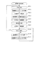
ここで、音声ランプメイン処理におけるステップS701のランプ部初期制御処理について図18を用いて説明する。ランプ部初期制御処理では、所定期間に亘りそれぞれの駆動手段としての各種ランプ部23〜25を試験駆動させる。この処理を実行することにより、各種ランプ部23〜25がそれぞれ正常に動作するか否かの動作チェックを行うことができる。
Here, the lamp unit initial control process of step S701 in the audio lamp main process will be described with reference to FIG. In the lamp unit initial control process, the
ステップS801では、立ち上げ処理として、記憶されているRAMの値が正常であるか否かを判定したり、RAMの初期化処理を行ったりする。また、所定周期毎に実行されるタイマ割込み処理を許可する割込みモードを設定する。その後CPU143内のレジスタ群や、I/O装置等に対する各種の設定などを行う。
In step S801, as startup processing, it is determined whether or not the stored RAM value is normal, or RAM initialization processing is performed. Also, an interrupt mode is set that permits timer interrupt processing to be executed at predetermined intervals. Thereafter, various settings are made for the register group in the
初期化処理を実行したらステップS802に進み、第1ランプ点灯処理を実行する。第1ランプ点灯処理では、環状電飾部23における上環状電飾部23aを点灯させる。上環状電飾部23aを点灯させたらステップS803に進み、第1期間が経過したか否かを判定する。この第1期間は上環状電飾部23aに設けられたLEDが正常に動作しているか否かを確認するのに十分な期間(例えば、3秒)となっている。第1期間が経過するまでステップS803にて待機する。上環状電飾部23aに設けられたLEDはそれぞれ赤、青、緑と複数色に発光できるタイプのものを使用しており、ステップS803の期間が終了するまでに、赤、青、緑の順番にてLEDを発光させ、赤、青、緑の発光を同時に行うことによって白色にてLEDを発光させる。すなわち、第1期間が経過するまでにLEDが赤→青→緑→白の順番に発光することとなる。
When the initialization process is executed, the process proceeds to step S802, and the first lamp lighting process is executed. In the first lamp lighting process, the upper
なお、本実施形態では、期間の計測をタイマ割込み処理にてカウンタの値を減算し、予め定められた値(例えば、0)になった場合に所定期間が経過したものと判定する。本実施形態におけるタイマ割込み処理は所定周期毎に行われるため、タイマ割込み処理の実行により所定期間の計測を良好に行うことができる。また、タイマ割込み処理にてカウンタの値を加算し、予め定められた値になった場合に所定期間が経過したものと判定してもよい。 In the present embodiment, the time period is measured by subtracting the counter value in the timer interrupt process, and when a predetermined value (for example, 0) is reached, it is determined that the predetermined period has elapsed. Since the timer interrupt process in the present embodiment is performed every predetermined period, the measurement of the predetermined period can be satisfactorily performed by executing the timer interrupt process. Alternatively, the counter value may be added in the timer interrupt process, and it may be determined that the predetermined period has elapsed when the value reaches a predetermined value.
ステップS803にて第1期間が経過したと判定した場合、ステップS804に進み第2ランプ点灯処理を実行する。第2ランプ点灯処理ではエラー表示ランプ部24及び賞球ランプ部25を点灯させる。
If it is determined in step S803 that the first period has elapsed, the process proceeds to step S804 to execute a second lamp lighting process. In the second lamp lighting process, the error
ステップS804にて第2ランプ点灯処理を実行したらステップS805に進み、第2期間(例えば3秒)が経過したか否かを判定し、第2期間が経過していなかった場合は、ステップS805の処理を繰り返す。ステップS805にて第2期間が経過していた場合、ステップS806に進み、上環状電飾部23aを消灯させる。本実施形態では、上環状電飾部23aとエラー表示ランプ部24及び賞球ランプ部25とが同時に点灯している期間が設けられている。上環状電飾部23aが消灯する前にエラー表示ランプ部24及び賞球ランプ部25が点灯することによって上環状電飾部23aの次に動作チェックするべき駆動機器(駆動手段)を把握することができる。すなわち、先に駆動させる先駆動手段と後に駆動させる後駆動手段とが設けられており、後駆動手段を駆動させた後に先駆動手段の駆動を停止させている。また、上述したようにエラー表示ランプ部24及び賞球ランプ部25は、パチンコ機10の上部に設けられている(図1)。上環状電飾部23aとエラー表示ランプ部24及び賞球ランプ部25とを同時に点灯することは、近接又は隣接した複数の駆動手段を同時に試験駆動させているともいえる。近接又は隣接した駆動手段を同時に駆動させることによって、動作チェックを行う場合に同時に広範囲に亘りチェック者が注意を払う必要がなくなる。
When the second lamp lighting process is executed in step S804, the process proceeds to step S805, where it is determined whether or not a second period (for example, 3 seconds) has elapsed. If the second period has not elapsed, the process proceeds to step S805. Repeat the process. When the second period has elapsed in step S805, the process proceeds to step S806, and the upper
第1ランプ消灯処理を実行したらステップS807に進み、第3期間(例えば、3秒
)が経過したか否かを判定し、第3期間が経過していなかった場合、第3期間が経過するまでこの処理を繰り返す。ステップS807にて第3期間が経過していた場合、ステップS808に進み、第3ランプ点灯処理を実行する。第3ランプ点灯処理では、下環状電飾部23bのLEDを点灯させる。
When the first lamp extinguishing process is executed, the process proceeds to step S807, where it is determined whether or not a third period (for example, 3 seconds) has elapsed, and if the third period has not elapsed, the third period has elapsed. This process is repeated. If the third period has elapsed in step S807, the process proceeds to step S808, and the third lamp lighting process is executed. In the third lamp lighting process, the LED of the lower annular illumination part 23b is turned on.
第3ランプ点灯処理を実行したらステップS809に進み、第4期間(例えば、6秒)が経過したか否かを判定し、第4期間が経過していなかった場合、第4期間が経過するまでこの処理を繰り返す。なお、下環状電飾部23bのLEDはこの期間において赤→青→緑→白の順番に発光色が切替えられる。ステップS809にて第4期間が経過していた場合、ステップS810に進み、ランプ消灯処理を実行する。このランプ消灯処理では、下環状電飾部23b、エラー表示ランプ部24及び賞球ランプ部25のLEDを消灯させる。すなわち、ステップS810のランプ消灯処理では第2,第3ランプ点灯処理にて点灯させたLEDを同時に消灯させる。すなわち、先に駆動される先駆動手段と、後に駆動される後駆動手段とが設けられており、先駆動手段及び後駆動手段が同時に停止しているともいえる。この場合、下環状電飾部23bのLEDが点灯されている状態にてエラー表示ランプ部24及び賞球ランプ部25のLEDが点灯されているため、その点灯をパチンコ機10前方から確認し易い。このため、下環状電飾部23b、エラー表示ランプ部24及び賞球ランプ部25のLEDが同時に消灯された場合に、それぞれのLEDが正常に動作しているか否かのチェックを阻害しない。ステップS810の処理を実行したら本ランプ部初期制御処理を終了する。
When the third lamp lighting process is executed, the process proceeds to step S809, where it is determined whether or not a fourth period (for example, 6 seconds) has elapsed. If the fourth period has not elapsed, the fourth period has elapsed. This process is repeated. In this period, the LED of the lower annular illumination portion 23b is switched in emission color in the order of red → blue → green → white. If the fourth period has elapsed in step S809, the process proceeds to step S810, and the lamp turn-off process is executed. In this lamp turn-off process, the LEDs of the lower annular illumination part 23b, the error
上環状電飾部23aと下環状電飾部23bとを異なるタイミングにて駆動させることは、パチンコ機10を前方から視認した場合に、各電飾部を異なる領域として設定し、各領域毎に駆動を実行しているともいえる。この場合、正常に駆動していない駆動機器を発見し易いものは同時に駆動しているともいえる。隣接して設けられた駆動機器(各環状電飾部23a,23bに設けられたLED)の駆動を同時に実行することにより、正常に駆動していない駆動機器を良好に発見できる。
Driving the upper
次に音声ランプメイン処理におけるスピーカ部初期制御処理について図19を用いて説明する。ランプ部初期制御処理では、所定期間に亘りそれぞれの駆動手段としての各スピーカ部26a,26b及び可動役物69を駆動させる。この処理を実行することにより、各スピーカ部26a,26b及び可動役物69がそれぞれ正常に動作するか否かの動作チェックを行うことができる。
Next, the speaker unit initial control process in the audio lamp main process will be described with reference to FIG. In the lamp unit initial control process, the speaker units 26a and 26b and the
ステップ901では、待機処理を実行する。待機処理では、予め定められた処理を所定回数繰り返す。待機処理を実行したら、ステップS902に進み、第1スピーカ部出力処理を実行する。第1スピーカ部出力処理では、第1スピーカ部26aから音声を出力させる。具体的には、第1スピーカ部26aから低音の音声を出力させた後に高音の音声を出力させる。高低の音声が出力されることによりその第1スピーカ部26aが正常に動作することを良好に確認できる。なお、本実施形態では、高低それぞれの音声が3秒ずつ出力される。ステップS901の待機処理を実行することにより、ランプ部初期制御処理が終了してから第1スピーカ部26aから音声の出力が開始されるまでに停止期間を設けることができる。停止期間を設けたことにより、動作チェック(LEDが発光しているか否か)を視覚にて行っていたものから、音声が出力されているか否かの聴覚による動作チェックに切替わる場合に動作チェックを行うチェック者がいずれの駆動手段の動作が行われているか把握しにくくなることを抑制できる。なお、本実施形態では、待機処理を実行することによって停止期間が約1秒間担保されるようになっている。 In step 901, standby processing is executed. In the standby process, a predetermined process is repeated a predetermined number of times. If a standby process is performed, it will progress to step S902 and a 1st speaker part output process will be performed. In the first speaker unit output process, sound is output from the first speaker unit 26a. Specifically, after the low sound is output from the first speaker unit 26a, the high sound is output. It can be confirmed well that the first speaker unit 26a operates normally by outputting high and low audio. In the present embodiment, high and low sounds are output for 3 seconds. By executing the standby process in step S901, a stop period can be provided from the end of the lamp unit initial control process to the start of audio output from the first speaker unit 26a. Operation check when switching from visual check of operation (whether LED is emitting light) to auditory check of whether sound is output or not by providing a stop period It can be suppressed that it becomes difficult for the checker who performs the operation to grasp which driving means is being operated. In the present embodiment, the stop period is secured for about 1 second by executing the standby process.
ステップS902にて第1スピーカ部26aからの音声の出力を実行したらステップS903に進み、第1出力期間(例えば6秒)が経過したか否かを判定する。第1出力期間が経過するまでステップS903の処理を繰り返す。ステップS903にて第1出力期間が経過したと判定した場合、ステップS904に進み、第1スピーカ部停止処理を実行する。第1スピーカ部停止処理では第1スピーカ部26aの出力を停止する。 If the audio output from the first speaker unit 26a is executed in step S902, the process proceeds to step S903 to determine whether or not a first output period (for example, 6 seconds) has elapsed. The process of step S903 is repeated until the first output period elapses. When it determines with the 1st output period having passed in step S903, it progresses to step S904 and performs a 1st speaker part stop process. In the first speaker unit stop process, the output of the first speaker unit 26a is stopped.
ステップS904にて第1スピーカ部26aの出力を停止したら、ステップS905に進み、待機処理を実行する。この待機処理はステップS901の待機処理と同様のものである。ステップS905における待機処理を実行したらステップS906に進み第2スピーカ部出力処理を実行する。第2スピーカ部出力処理では、第2スピーカ部26bに対して第1スピーカ部出力処理と同様の処理を実行する。ステップS905にて待機処理を実行することにより、第1スピーカ部26aの出力の停止から第2スピーカ部26bの出力の開始までに停止期間を設けることができる。この停止期間(ステップS905)を設けたことにより、異なる音声出力手段としての複数のスピーカ部26a,26bの駆動が実行される場合に、いずれのスピーカ部から音声が出力されているかをチェック者が理解できなくなることを抑制できる。 When the output of the first speaker unit 26a is stopped in step S904, the process proceeds to step S905, and standby processing is executed. This standby process is the same as the standby process in step S901. If the standby process in step S905 is executed, the process proceeds to step S906, and the second speaker unit output process is executed. In the second speaker unit output process, the same process as the first speaker unit output process is performed on the second speaker unit 26b. By executing the standby process in step S905, a stop period can be provided from the stop of the output of the first speaker unit 26a to the start of the output of the second speaker unit 26b. By providing this stop period (step S905), when driving a plurality of speaker units 26a and 26b as different audio output means, a checker can determine which speaker unit is outputting audio. It is possible to suppress the inability to understand.
ステップS906にて第2スピーカ部出力処理を実行したらステップS907に進み、
第2出力期間(例えば、6秒)が経過したか否かを判定する。第2出力期間が経過するまでステップS907の処理を繰り返す。ステップS907にて第2出力期間が経過したと判定した場合、ステップS908に進み、第2スピーカ部停止処理を実行する。第2スピーカ部停止処理では、第2スピーカ部26bの出力を停止する。
If the 2nd speaker part output processing is performed in Step S906, it will progress to Step S907,
It is determined whether or not a second output period (for example, 6 seconds) has elapsed. The process of step S907 is repeated until the second output period elapses. When it determines with the 2nd output period having passed in step S907, it progresses to step S908 and performs a 2nd speaker part stop process. In the second speaker unit stop process, the output of the second speaker unit 26b is stopped.
第2スピーカ部出力処理を実行したらステップS909に進み、可動役物制御処理を実行する。可動役物制御処理では、可動役物69における駆動モータ110を駆動させ装飾部100を回転させる。その後にステップS910に進み、位置検出センサ116によるスリット部117の検出が行われるまで装飾部100を回転させ続ける。位置検出センサ116によるスリット部117の検出が行われた場合、ステップS911に進み、位置検出センサ初期設定処理を行う。この位置検出センサ初期設定処理により、位置検出センサ116によるスリット部117の検出があった位置を基点として装飾部100の回転位置を把握することができる。位置検出センサ初期設定処理を実行したら本スピーカ部初期制御処理を終了する。
If a 2nd speaker part output process is performed, it will progress to step S909 and a movable accessory control process will be performed. In the movable accessory control process, the
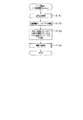
次に、本パチンコ機10における音声ランプ制御装置70にて使用される電気量について説明する。なお、駆動されている場合と駆動されていない場合とでパチンコ機10全体にて使用される電流の値が大きく変動する駆動機器として、各環状電飾部23a,23b、各スピーカ部26a,26b及び可動役物69にて消費される電流値について説明する。
Next, the amount of electricity used in the sound
各々の駆動機器が使用する電流量について説明する。各環状電飾部23a,23bが駆動される場合はそれぞれ最大0.5Aの電流を消費し、各スピーカ部26a,26bが駆動される場合ではそれぞれ最大7Aの電力が消費される。また、可動役物69が駆動される場合は5Aの電流が使用される。なお、それぞれの駆動機器によって消費される電流は以上のものに限られるものではなく、例えば、各スピーカ部26a,26bにて消費される電流が5A、10Aであってもよい。
The amount of current used by each driving device will be described. When each of the
本実施形態では、パチンコ機10に電源が投入されており、遊技が進行されている場合(すなわち、主制御装置72による通常処理が実行されている場合)、他の遊技状態と比して大当たり状態における瞬間最大消費電流が大きい。具体的には、大当たり状態では図20(a)に示すように、各環状電飾部23a,23b、各スピーカ部26a,26bが最大消費電流にて同時に駆動することがあり、この場合、音声ランプ制御装置70によって消費される電流が15Aとなる。
In the present embodiment, when the
次に音声ランプ制御装置70の各初期制御処理が実行される場合における消費電流について図20(b)を用いて説明する。
Next, current consumption when each initial control process of the sound
各初期制御処理では、先ず、タイミングt1にて上環状電飾部23aが点灯される(ランプ部初期制御処理におけるステップS802)。この場合、上環状電飾部23aのみが点灯されていることとなり、消費電流は0.5Aとなる。次にタイミングt2にてエラー表示ランプ部24及び賞球ランプ部25が点灯される(ランプ部初期制御処理におけるステップS804)。この場合、上環状電飾部23a、エラー表示ランプ部24、賞球ランプ部25が点灯されている。エラー表示ランプ部24及び賞球ランプ部25は、各環状電飾部23a,23bと比して設置されているLEDの数が少ない。エラー表示ランプ部24及び賞球ランプ部25が点灯されている場合には、0.1Aの電流を消費する。これにより、タイミングt2からタイミングt3の期間における消費電流は0.6Aとなる。
In each initial control process, first, the upper
タイミングt3にて上環状電飾部23aが消灯され(ランプ部初期制御処理におけるステップS806)、タイミングt4にて下環状電飾部23bが点灯される(ランプ部初期制御処理におけるステップS808)。タイミングt3からタイミングt4までの期間は、エラー表示ランプ部24及び賞球ランプ部25が点灯されており、消費電流は0.1Aとなる。
The upper
タイミングt5にて下環状電飾部23b、エラー表示ランプ部24及び賞球ランプ部25が消灯され(ランプ部初期制御処理におけるステップS810)、タイミングt6にて第1スピーカ部26aから音声が出力される(スピーカ部初期制御処理におけるS902)。すなわち、タイミングt5からタイミングt6までの期間が上述した停止期間となっている。そして、タイミングt7にて第1スピーカ部26aからの音声出力が停止される(スピーカ部初期制御処理におけるステップS904)。タイミングt6からタイミングt7の期間は第1スピーカ部26aのみが駆動されていることとなり、この期間における消費電流は7Aとなる。
The lower annular illumination part 23b, the error
タイミングt8にて第2スピーカ部26bから音声が出力される(スピーカ部初期制御処理におけるステップS906)。すなわち、タイミングt7からタイミングt8までの期間が停止期間となっている。そして、タイミングt9にて第2スピーカ部26bからの音声出力が停止される(スピーカ部初期制御処理におけるステップS908)。タイミングt8からタイミングt9の期間は第1スピーカ部26aのみが駆動されていることとなり、この期間における消費電流は7Aとなる。 Audio is output from the second speaker unit 26b at timing t8 (step S906 in the speaker unit initial control process). That is, the period from timing t7 to timing t8 is a stop period. Then, the audio output from the second speaker unit 26b is stopped at timing t9 (step S908 in the speaker unit initial control process). During the period from timing t8 to timing t9, only the first speaker unit 26a is driven, and the current consumption during this period is 7A.
また、タイミングt9では、可動役物69が駆動される(ランプ部初期制御処理におけるステップS909)。タイミングt10にて可動役物69の駆動が停止される(スピーカ部初期制御処理におけるステップS911)。タイミングt9からタイミングt10までの期間では、可動役物69のみが駆動していることとなり、この期間における消費電流は5Aとなる。
At timing t9, the
本実施形態では、上環状電飾部23aと下環状電飾部23bとがそれぞれ同期間(例えば、6秒ずつ)に亘り駆動されるようになっている。また、第1スピーカ部26aと第2スピーカ部26bとがそれぞれ同期間(例えば、6秒ずつ)に亘り駆動されるようになっている。すなわち、同じ機能を有した駆動手段は同期間に亘り駆動されるようになっている。
In the present embodiment, the upper
エラー表示ランプ部24及び賞球ランプ部25の駆動は、各環状電飾部23a,23b及び各スピーカ部26a,26bと比して、長期間に亘り駆動される。特に、エラー表示ランプ部24は、パチンコ機10にエラーが発生していることを報知するものであり、エラー表示ランプ部24が正常に駆動されない場合には、パチンコ機10に不具合が発生し易い。すなわち、正常に駆動されない場合に不具合が発生し易い駆動手段の駆動を長期間に亘り実行している。これにより、初期制御処理にて動作チェックを行う場合に、その駆動手段が正常に駆動されていないことを見逃してしまうことを抑制できる。
The error
また、可動役物69は、位置検出センサ116によるスリット部117の検出が行われるまでその駆動を実行し続けるものとした。上述したように、可動役物69はその回転位置によって大当たり抽選に当選していることを教示するものであり、可動役物69の動きに遊技者は注目して遊技を行っているものと考えられる。すなわち、検出手段を有した駆動手段は、検出手段による検出が行われるまでその駆動を実行し続けている。これにより、演出を実行する上で重要度の高い駆動手段が正常に駆動されない状態にて遊技が進行することを抑制できる。
The
上記のように本実施形態では、各初期制御処理が実行される場合に消費される電流値が15Aを上回ることがなく、大当たり状態における音声ランプ制御装置70の瞬間消費電流値を、各初期制御処理が行われる場合における音声ランプ制御装置70の瞬間消費電流値が上回ることを抑制している。
As described above, in the present embodiment, the current value consumed when each initial control process is executed does not exceed 15 A, and the instantaneous current consumption value of the sound
特に、各種ランプ部23〜25、スピーカ部26及び可動役物69は、それぞれDC12Vの電圧が印加されることによって駆動される。すなわち、同一のレギュレータにより変換された電圧が複数の駆動手段に印加されている。各種ランプ部23〜25、スピーカ部26及び可動役物69がそれぞれDC12Vの電圧が印加されることによって駆動するため、各駆動手段が同時に駆動する場合には、電圧変換回路151におけるレギュレータのDC12Vに変換する電気量が大きくなってしまう。この場合、そのレギュレータの電気容量を大きくする必要がある。本実施形態によれば、各初期制御処理において各種ランプ部23〜25、スピーカ部26及び可動役物69の全てが同時に駆動することを抑制し、各種ランプ部23〜25、スピーカ部26及び可動役物69の全てが同時に駆動する構成と比して、レギュレータの電気容量を大きくしなくとも不具合が発生しない。よって、同一のレギュレータにより変換された電圧が複数の駆動手段に印加される場合に不具合が発生しない。
In particular, the
上述したように保護カバー部83の背面側に動作チェックシール84が貼り付けられている。動作チェックシール84には各初期制御処理にて駆動される各駆動機器の順番が示されており、音声ランプ制御装置70による各初期制御処理が行われる場合に駆動される各駆動機器の順番を良好に把握することができる。
As described above, the
具体的には、図21に示すように、動作チェックシール84には、パチンコ機10を正面から視認した場合の概略図が記載されている。そして、上環状電飾部23aが最初に駆動されることを示す番号Aが付されており、エラー表示ランプ部24及び賞球ランプ部25に2番目に駆動されることを示す番号Bが付されている。同様に、下環状電飾部23bが3番目に駆動されることを示す番号Cが付されており、第1スピーカ部26aが4番目に駆動されることを示す番号Dが付されている。また、第2スピーカ部26bが5番目に駆動されることを示す番号Eが付されており、可動役物69が6番目に駆動されることを示す番号Fが付されている。これにより、上環状電飾部23a→エラー表示ランプ部24及び賞球ランプ部25→下環状電飾部23b→第1スピーカ部26a→第2スピーカ部26b→可動役物69の順番に駆動されることをチェック者が混乱することなく理解できる。
Specifically, as shown in FIG. 21, the
以上詳述した本実施の形態によれば、以下の優れた効果を奏する。 According to the embodiment described in detail above, the following excellent effects are obtained.
音声ランプ制御装置70における各初期制御処理において各駆動機器が駆動される。これにより、各駆動機器が正常に駆動するか否かの動作チェックを良好に行うことができる。本実施形態によれば、全ての各駆動機器が同時に駆動されることがない。よって、瞬間最大電流が大きくなってしまい電源・発射制御装置92にかかる生産コストが増大することを抑制することができる。具体的には、各環状電飾部23a,23bの駆動が終了された場合に、各スピーカ部26a,26bの駆動が開始される。これにより、パチンコ機10において消費される瞬間最大電流を抑制することができる。
Each drive device is driven in each initial control process in the sound
また、エラー表示ランプ部24及び賞球ランプ部25は、各環状電飾部23a,23bと同時に駆動される期間を設けた。仮に、全ての駆動機器の駆動が重複することなく行われたとすると、パチンコ機10における全ての駆動機器の動作チェックを行うために長期間を要することが考えられる。例えば、複数の遊技機を設置している遊技ホールもあり、一の遊技機に対する動作チェックに長期間を要した場合、全ての遊技機に対して動作チェックを行うことが困難なものとなってしまうことが考えられる。これに対して上記実施形態によれば、エラー表示ランプ部24及び賞球ランプ部25と各環状電飾部23a,23bとが駆動される期間を設けたため、駆動機器の動作チェックに要する期間を短くすることが可能となる。特に、エラー表示ランプ部24及び賞球ランプ部25は消費電流が他の駆動機器(各スピーカ部26a,26b、可動役物69)よりも小さいため、瞬間最大電流を最小限に抑えつつ、上記駆動手段の動作チェックに要する期間を短くする効果を得ることができる。
In addition, the error
上環状電飾部23a及び下環状電飾部23bはそれぞれ複数のLEDにて構成されており、その複数のLEDをそれぞれランプ部初期制御処理において同時に駆動した。これにより、近接(隣接)して設けられているLEDが同時に発光する。また、各環状電飾部23a,23bにおけるLEDをそれぞれ同時に発光させるということは、発光機能を有した駆動機器を同時に駆動させているということもできる。複数の発光体が設けられており、複数の発光体のうち一部の発光体が発光しており残りの一部の発光体が発光していない場合、光が照射されている部分と光が照射されていない部分とが設けられることとなり、発光していない発光体を良好に発見できる。これにより、正常に駆動していないLEDを良好に発見することができる。
The upper
各初期制御処理においては、遊技の進行に伴い使用される最大電流よりも小さい電流にて各駆動機器が駆動される。遊技の進行に伴い使用される最大電流よりも小さい電流にて点検動作が実行されるため、電源・発射制御装置92の電源容量を大きくする必要がなく、電源・発射制御装置92にかかる生産コストを抑えつつ、各駆動機器の動作チェックを良好に行うことができる。
In each initial control process, each drive device is driven with a current smaller than the maximum current used as the game progresses. Since the inspection operation is performed with a current smaller than the maximum current used as the game progresses, it is not necessary to increase the power capacity of the power /
可動役物69の装飾部100の停止位置によって遊技結果が教示される。例えば、装飾部100の検出位置がずれている場合、装飾部100によって遊技結果が正常に教示されなくなってしまうことが考えられる。本実施形態によれば、各初期制御処理が実行される場合に位置検出センサ116による検出位置の調整が行われるため、可動役物69によって遊技結果が正常に教示されなくなることを抑制できる。これにより、各種駆動機器の動作チェックを良好に行いつつ、可動役物69のメンテナンスを良好に行う効果が得られる。
The game result is taught by the stop position of the
動作チェックシール84をパチンコ機10の内部に貼着させる構成とした。動作チェックシール84を視認することによって作業者は試験駆動される各種機器の順番を把握することができるため、各種機器の駆動が開始されてからどの駆動機器が駆動しているかをチェックする必要がなくなり、動作チェックに要する期間を短くすることができる。
The
なお、上述した実施の形態の記載内容に限定されず、例えば次のように実施してもよい。ちなみに、以下の各構成を相互に適用してもよい。 In addition, it is not limited to the description content of embodiment mentioned above, For example, you may implement as follows. Incidentally, the following configurations may be applied to each other.
(1)音声ランプ制御装置70におけるランプ部初期制御処理において、下環状電飾部23bの駆動とエラー表示ランプ部24及び賞球ランプ部25の駆動とが同時に終了される必要はなく、下環状電飾部23bの駆動が終了された後、又は下環状電飾部23bの駆動が終了される前に、エラー表示ランプ部24及び賞球ランプ部25の駆動が終了されてもよい。
(1) In the lamp initial control process in the sound
上環状電飾部23a、下環状電飾部23bの2種類の部分にわけて環状電飾部23の駆動を実行したが、環状電飾部23の駆動を全て同時に行ってもよい(上及び下環状電飾部23a,23bの試験駆動を同時に実行する)。また、環状電飾部23の駆動を3種類以上の部分に分けて行ってもよい。例えば、環状電飾部23を左上環状電飾部、左下環状電飾部、右上環状電飾部、右下環状電飾部の4種類の部分にわけて駆動を実行するものが考えられる。
Although driving of the
(2)音声ランプ制御装置70による各初期制御処理において駆動される駆動機器の順序を変更してもよく、例えば、各スピーカ部26a,26bの駆動が実行された後に、各ランプ部23〜25の駆動が実行されてもよい。この場合、駆動が実行される順序に合わせて動作チェックシール84に記載されている駆動が実行される順序を変更すればよい。
(2) The order of the driving devices driven in each initial control process by the audio
同時に駆動が実行される駆動機器の組合せを変更してもよく、異なる機能を有した駆動機器の駆動を同時に行ってもよい。異なる機能の組合せとして、発光機能を有した駆動機器と音声発生機能を有した駆動機器とを同時に駆動させるものが考えられる。例えば、第1スピーカ部26aと、エラー表示ランプ部24及び賞球ランプ部25と、が同時に駆動されるものが考えられる。この場合、動作チェックを行うチェック者は視覚と聴覚とによって駆動機器の動作チェックを行うことが可能となり、複数の駆動機器の動作チェックを効率よく行うことができる。
Combinations of drive devices that are simultaneously driven may be changed, and drive devices having different functions may be driven simultaneously. As a combination of different functions, a driving device having a light emitting function and a driving device having a sound generation function can be simultaneously driven. For example, the first speaker unit 26a, the error
(3)動作チェックシール84が設けられている位置を変更してもよく、例えば、制御ユニット71の背面側に設けられていてもよい。但し、パチンコ機10において遊技が進行している場合に遊技者に視認されない位置に設けておくのが望ましい。
(3) The position where the
(4)各駆動機器によって消費される最大電流値をそれぞれ変更してもよく、例えば、各環状電飾部23a,23bにて消費される最大電流値が1,2,3A等どのような大きさの電流が消費されてもよい。各スピーカ部26a,26b、可動役物69においても同様にいずれの大きさの最大電流が消費されてもよい。また、それぞれの駆動機器の駆動が実行される場合に印加される電圧の大きさを変更してもよく、例えば、環状電飾部23に印加される電圧が24Vであってもよい。パチンコ機10にて遊技が進行される場合に消費される最大電流よりも、各初期制御処理において同時に駆動される駆動機器の消費電流の合計が小さくなるようにすればよい。
(4) The maximum current value consumed by each driving device may be changed. For example, the maximum current value consumed by each of the
(5)可動役物制御処理(スピーカ部初期制御処理におけるステップS909)が実行される場合、位置検出センサ116による位置検出(スリット部117の検出)が行われるまで可動役物69の駆動が実行されたが、所定期間に亘り可動役物69の駆動が実行されてもよい。この場合、可動役物69における装飾部100が少なくとも1周はできる期間に亘り可動役物69の駆動が実行されることが望ましい。装飾部100が1周できない期間しか可動役物69の試験駆動が実行されないとすると、位置検出センサ116による位置検出が行われる前に可動役物69の試験駆動が終了してしまい装飾部100の位置調整が行われない可能性があるからである。なお、装飾部100が1周する期間において位置検出センサ116により位置検出が行われなった場合、エラー報知をするようにしてもよい。
(5) When the movable accessory control process (step S909 in the speaker unit initial control process) is executed, the
また、可動役物が複数個設けられている遊技機においては、それぞれの可動役物に対して試験駆動が実行されてもよい。 Further, in a gaming machine provided with a plurality of movable accessories, a test drive may be executed for each movable accessory.
(6)パチンコ機10の電源投入時に各初期制御処理が実行される必要はなく、音声ランプ制御装置70における各初期制御処理が行われるタイミングを変更してもよい。例えば、試験駆動スイッチが設けられており、当該スイッチが操作されることにより各初期制御処理が行われるものが考えられる。この場合、パチンコ機10を設置している遊技店の管理者等が動作チェックを行う場合にのみ各種駆動機器の試験駆動を実行することができる。また、各初期制御処理を行うべく操作される操作手段とその他の操作手段と兼用しておけば、パチンコ機10における部品数が増加することを抑制できる。その他の操作手段として例えば、RAM消去スイッチ等が考えられる。
(6) It is not necessary to execute each initial control process when the
(7)各種駆動機器の試験駆動は音声ランプ制御装置70よる各初期制御処理において行われたが、いずれの制御装置にて初期制御処理が行われてもよい。例えば、主制御装置72において初期制御処理が行われてもよい。この場合、主制御装置72によって制御される可変入賞装置53、第1,第2特定ランプ部63,64、保留ランプ部65,66の動作チェックを行うことができる。
(7) The test drive of the various drive devices is performed in each initial control process by the sound
複数の制御装置が制御する駆動機器の動作チェックがそれぞれ行われる場合、各制御装置による駆動機器の試験駆動が同時に行われないことが望ましい。一の制御装置による試験駆動が終了した場合に、その他の制御装置による試験駆動が開始されるようにすればよい。上記実施形態に適用する場合、主制御装置72による試験駆動が終了した場合に、主制御装置72から音声ランプ制御装置70に対して主制御装置72による試験駆動が終了したことに対応したコマンドを出力すればよい。また、音声ランプ制御装置70は、当該コマンドを受信したことに基づいて各初期制御処理の実行を開始すればよい。この場合、当該コマンドを受信したことに基づいて音声ランプ制御装置70による音声ランプメイン処理を開始するようにしてもよい。
When operation checks of driving devices controlled by a plurality of control devices are performed, it is preferable that test driving of the driving devices by the control devices is not performed simultaneously. What is necessary is just to start the test drive by another control apparatus, when the test drive by one control apparatus is complete | finished. When applied to the above embodiment, when the test drive by the
(8)主制御装置72から表示制御装置145に出力されたコマンドに基づいて、図柄表示装置146における図柄の変動表示が行われてもよい。
(8) Based on the command output from the
また、音声ランプ制御装置70と表示制御装置145とが一の装置であり、当該装置に主制御装置72からコマンドが出力されることによって演出や図柄の変動表示が行われてもよい。この場合、各初期制御処理を当該一の装置が実行すればよい。
Further, the sound
(9)電源・発射制御装置92は、同じ基板ボックス内に配されている必要はなく、電力供給手段としての電源と、発射制御装置とが個別に設けられていても良い。
(9) The power source /
(10)上記実施の形態とは異なる他のタイプの弾球遊技機、例えば他の役物を備えたパチンコ機、アレンジボール機、雀球等の遊技機にも適用できる。 (10) The present invention can also be applied to other types of ball and ball game machines different from the above-described embodiment, for example, game machines such as a pachinko machine, an arrange ball machine, and a sparrow ball equipped with other objects.
また、弾球式でない遊技機、例えば、複数種の図柄が周方向に付された複数のリールを備え、メダルの投入及びスタートレバーの操作によりリールの回転を開始し、ストップスイッチが操作されるか所定期間が経過することでリールが停止した後に、表示窓から視認できる有効ライン上に特定図柄又は特定図柄の組合せが成立していた場合にはメダルの払い出し等といった特典を遊技者に付与するスロットマシンにも、本発明を適用できる。 Also, a non-ball-type gaming machine, for example, a plurality of reels with a plurality of types of symbols attached in the circumferential direction, starts rotation of the reel by inserting a medal and operating a start lever, and a stop switch is operated. If a specific symbol or a combination of specific symbols is established on an effective line visible from the display window after the reel has stopped after a predetermined period of time, a privilege such as paying out medals is given to the player The present invention can also be applied to a slot machine.
また、取込装置を備え、貯留部に貯留されている所定数の遊技球が取込装置により取り込まれた後にスタートレバーが操作されることによりリールの回転を開始する、パチンコ機とスロットマシンとが融合された遊技機にも、本発明を適用できる。 In addition, a pachinko machine and a slot machine that have a take-in device and start rotation of a reel by operating a start lever after a predetermined number of game balls stored in the storage unit are taken in by the take-in device The present invention can also be applied to a gaming machine in which is integrated.
(11)上述した実施形態における構成及び別例における各構成のそれぞれを任意に組み合わせた構成としてもよい。例えば、一の実施形態の構成に対して、その他の実施形態の構成を適用してもよい。また、3パターン以上の実施形態の構成を相互に適用してもよい。 (11) It is good also as a structure which combined each of the structure in embodiment mentioned above and each structure in another example arbitrarily. For example, the configuration of another embodiment may be applied to the configuration of one embodiment. Further, the configurations of the embodiments having three or more patterns may be applied to each other.
<上記実施の形態から抽出される発明群について>
以下、上述した実施の形態から抽出される発明群の特徴について、必要に応じて効果等を示しつつ説明する。なお以下においては、理解の容易のため、上記実施の形態において対応する構成を括弧書き等で適宜示すが、この括弧書き等で示した具体的構成に限定されるものではない。
<Invention Group Extracted from the Embodiments>
Hereinafter, the features of the invention group extracted from the above-described embodiment will be described while showing effects and the like as necessary. In the following, for easy understanding, the corresponding configuration in the above embodiment is appropriately shown in parentheses, but is not limited to the specific configuration shown in parentheses.
特徴1.遊技機各部に電力を供給する電力供給手段(電源・発射制御装置92)と、
前記電力供給手段から電力を受けて駆動される複数の駆動手段(各環状電飾部23a,23b、各スピーカ部26a,26b等)と、
前記各駆動手段を駆動制御する駆動制御手段(音声ランプ制御装置70)と、
を備えた遊技機において、
前記駆動制御手段は、前記各駆動手段を制御してその駆動が確認可能となる点検動作を前記各駆動手段について実行させるとともに、前記各駆動手段のうち第1駆動手段及び第2駆動手段の点検動作を期間の重複なく実行させる点検制御手段(音声ランプ制御装置70によるランプ部初期制御処理及びスピーカ部初期制御処理)を有することを特徴とする遊技機。
A plurality of driving means driven by receiving electric power from the power supply means (
Drive control means (sound lamp control device 70) for driving and controlling each of the drive means;
In a gaming machine equipped with
The drive control means controls each of the drive means to perform an inspection operation on the drive means so that the drive can be confirmed, and checks the first drive means and the second drive means among the drive means. A gaming machine comprising inspection control means (a lamp unit initial control process and a speaker unit initial control process by the sound lamp control device 70) for executing the operation without overlapping of periods.
特徴1によれば、点検制御手段により複数の駆動手段の点検動作が実行される。第1駆動手段や第2駆動手段が正常に駆動することによって遊技が進行したり演出が実行されたりする遊技機においては、それら第1駆動手段や第2駆動手段が正常に駆動するか否かの動作チェックを行うことが望ましい。本特徴によれば、第1駆動手段と第2駆動手段とについて点検動作がそれぞれ実行されるためそれぞれの駆動手段の動作チェックを良好に行うことができる。
According to the
また、仮に、第1駆動手段と第2駆動手段とが同時に駆動されると、一の駆動手段のみを駆動する場合と比して、その駆動によって消費される瞬間最大電力が大きくなることが考えられる。この場合、その瞬間最大電力に対応した電源容量を有した電源供給手段を遊技機に設ける必要が生じ、電力供給手段の電源容量が大きくなることによって電力供給手段にかかる生産コストが大きくなってしまうことが考えられる。これに対して本特徴によれば、第1駆動手段と第2駆動手段との点検動作の期間が重複しない。すなわち、第1駆動手段と第2駆動手段とが同時に駆動されることがなく、瞬間最大電力が大きくなってしまい電力供給手段にかかる生産コストが増大することを抑制できる。よって、駆動手段の動作チェックを良好に行う効果を高めることができる。 Also, if the first driving means and the second driving means are driven simultaneously, it is considered that the instantaneous maximum power consumed by the driving becomes larger than when only one driving means is driven. It is done. In this case, it is necessary to provide the gaming machine with a power supply means having a power capacity corresponding to the instantaneous maximum power, and the power supply capacity of the power supply means increases, resulting in an increase in production cost for the power supply means. It is possible. On the other hand, according to this feature, the inspection operation periods of the first drive means and the second drive means do not overlap. That is, the first driving means and the second driving means are not driven at the same time, and it is possible to prevent the instantaneous maximum power from increasing and the production cost for the power supply means from increasing. Therefore, it is possible to enhance the effect of favorably checking the operation of the driving unit.
特徴2.遊技機各部に電力を供給する電力供給手段(電源・発射制御装置92)と、
前記電力供給手段から電力を受けて駆動される複数の駆動手段(各環状電飾部23a,23b、各スピーカ部26a,26b等)と、
前記各駆動手段を駆動制御する駆動制御手段(音声ランプ制御装置70)と、
を備えた遊技機において、
前記駆動制御手段は、前記各駆動手段を制御してその駆動が確認可能となる点検動作を前記各駆動手段について実行させるとともに、前記各駆動手段のうち第1駆動手段の点検動作が終了した場合に第2駆動手段の点検動作を開始させる点検制御手段(音声ランプ制御装置70によるランプ部初期制御処理及びスピーカ部初期制御処理)を有することを特徴とする遊技機。
A plurality of driving means driven by receiving electric power from the power supply means (
Drive control means (sound lamp control device 70) for driving and controlling each of the drive means;
In a gaming machine equipped with
The drive control means controls each of the drive means to cause the drive means to execute an inspection operation that allows the drive to be confirmed, and when the check operation of the first drive means among the drive means is completed The game machine further comprises inspection control means for starting the inspection operation of the second drive means (lamp part initial control processing and speaker part initial control processing by the sound lamp control device 70).
特徴2によれば、点検制御手段により複数の駆動手段の点検動作が実行される。第1駆動手段や第2駆動手段が正常に駆動することによって遊技が進行したり演出が実行されたりする遊技機においては、それら第1駆動手段や第2駆動手段が正常に駆動するか否かの動作チェックを行うことが望ましい。本特徴によれば、第1駆動手段と第2駆動手段とについて点検動作がそれぞれ実行されるためそれぞれの駆動手段の動作チェックを良好に行うことができる。
According to the
また、仮に、第1駆動手段と第2駆動手段とが同時に駆動されると、一の駆動手段のみを駆動する場合と比して、その駆動によって消費される瞬間最大電力が大きくなることが考えられる。この場合、その瞬間最大電力に対応した電源容量を有した電力供給手段を遊技機に設ける必要が生じ、電力供給手段の電源容量が大きくなることによって電力供給手段にかかる生産コストが大きくなってしまうことが考えられる。これに対して本特徴によれば、第1駆動手段の点検動作が終了した場合に第2駆動手段の点検動作が開始されるため、第1駆動手段と第2駆動手段とが同時に駆動されることを抑制し、瞬間最大電力が大きくなってしまい電力供給手段にかかる生産コストが増大することを抑制できる。よって、駆動手段の動作チェックを良好に行う効果を高めることができる。 Also, if the first driving means and the second driving means are driven simultaneously, it is considered that the instantaneous maximum power consumed by the driving becomes larger than when only one driving means is driven. It is done. In this case, it is necessary to provide the game machine with a power supply means having a power supply capacity corresponding to the instantaneous maximum power, and the power supply capacity of the power supply means increases, resulting in an increase in production cost for the power supply means. It is possible. On the other hand, according to this feature, since the inspection operation of the second drive means is started when the inspection operation of the first drive means is completed, the first drive means and the second drive means are driven simultaneously. It is possible to suppress the increase in production cost for the power supply means due to the increase in the instantaneous maximum power. Therefore, it is possible to enhance the effect of favorably checking the operation of the driving unit.
特徴3.遊技機各部に電力を供給する電力供給手段(電源・発射制御装置92)と、
前記電力供給手段から電力を受けて駆動される複数の駆動手段(各環状電飾部23a,23b、各スピーカ部26a,26b等)と、
前記各駆動手段を駆動制御する駆動制御手段(音声ランプ制御装置70)と、
を備えた遊技機において、
前記駆動制御手段は、
遊技の進行に伴い前記各駆動手段を駆動制御する遊技駆動制御手段(音声ランプ制御装置70による音声ランプメイン処理におけるステップS705〜S714等)と、
前記各駆動手段を制御してその駆動が確認可能となる点検動作を前記各駆動手段について実行させるとともに、前記遊技駆動制御手段による駆動制御の場合に使用される最大電力を超えないよう各駆動手段の点検動作の期間をずらして実行させる点検制御手段(音声ランプ制御装置70によるランプ部初期制御処理及びスピーカ部初期制御処理)と、
を有することを特徴とする遊技機。
A plurality of driving means driven by receiving electric power from the power supply means (
Drive control means (sound lamp control device 70) for driving and controlling each of the drive means;
In a gaming machine equipped with
The drive control means includes
Game drive control means (steps S705 to S714 in the sound lamp main process by the sound lamp control device 70) for driving and controlling each of the drive means as the game progresses,
Each driving means is controlled so that the driving operation can be confirmed for each driving means, and the driving power by the game driving control means is not exceeded. Inspection control means (lamp part initial control process and speaker part initial control process by the sound lamp control device 70) to be executed while shifting the period of the inspection operation of
A gaming machine characterized by comprising:
特徴3によれば、遊技の進行に伴い使用される最大電力を超えないように各駆動手段の点検動作の期間をずらして実行される。複数の駆動手段が正常に駆動することによって遊技が進行したり演出が実行されたりする遊技機においては、それら駆動手段が正常に駆動するか否かの動作チェックを行うことが望ましい。本特徴によれば、複数の駆動手段について点検動作が実行されるため複数の駆動手段の動作チェックを良好に行うことができる。
According to the
仮に、点検動作が実行される場合に、点検動作となっていない場合に使用される最大電力よりも大きい電力を要すると、点検動作が実行される場合に使用される電力に対応した電源容量を有した電源供給手段を使用する必要が生じてしまう。これに対して本特徴によれば、遊技の進行に伴い使用される最大電力よりも小さい電力にて点検動作が実行されるため、電源供給手段の電源容量を大きくする必要がなく、電源供給手段にかかる生産コストを抑えつつ、駆動手段の点検作業を良好に行うことができる。 If the inspection operation is performed and the power required is larger than the maximum power used when the inspection operation is not performed, the power capacity corresponding to the power used when the inspection operation is performed is reduced. It becomes necessary to use the power supply means. On the other hand, according to this feature, since the inspection operation is performed with power smaller than the maximum power used as the game progresses, it is not necessary to increase the power capacity of the power supply means, and the power supply means Thus, it is possible to satisfactorily perform the inspection work of the driving means while suppressing the production cost.
特徴4.特徴1又は2において、前記点検制御手段は、前記第1駆動手段の点検動作を実行している期間の少なくとも一部において前記各駆動手段のうち第3駆動手段の点検動作を実行させることを特徴とする遊技機。
特徴4によれば、第1駆動手段の点検動作が実行されている少なくとも一部の期間において第3駆動手段の駆動が実行される。仮に、全ての駆動手段の点検動作が重複することなく行われたとすると、遊技機における全ての駆動手段の動作チェックを行うために長期間を要することが考えられる。例えば、複数の遊技機を設置している遊技ホールもあり、一の遊技機に対する動作チェックに長期間を要した場合、全ての遊技機に対して動作チェックを行うことが困難なものとなってしまうことが考えられる。これに対して本特徴を適用した場合、第1駆動手段と第3駆動手段との両方の点検動作が行われている期間を設けたため、上記瞬間最大電力を最小限に抑えつつ、駆動手段の動作チェックに要する期間を短くすることが可能となる。
According to the
特徴5.特徴4において、前記第3駆動手段は、前記第1及び第2駆動手段よりもその駆動によって消費する電力が小さいことを特徴とする遊技機。
特徴5によれば、第1,第2駆動手段のよりも第3駆動手段の方が消費電力が小さい。これにより、第1駆動手段と第2駆動手段とが同時に駆動される場合と比して、第1駆動手段と第3駆動手段との駆動が同時に行われても、それらの駆動によって消費される電力が大きくなることを抑制できる。よって、上記瞬間最大電力を最小限にする効果を高めることができる。
According to the
特徴6.特徴1乃至5のいずれか1において、前記点検制御手段は、前記各駆動手段のうち同じ種類の駆動手段の点検動作を同時に実行することを特徴とする遊技機。
Feature 6 The gaming machine according to any one of the
特徴6によれば、同じ種類の駆動手段の点検動作が同時に実行される。仮に、全ての駆動手段の点検動作が重複することなく行われたとすると、遊技機における全ての駆動手段の動作チェックを行うために長期間を要することが考えられる。例えば、複数の遊技機を設置している遊技ホールもあり、一の遊技機に対する動作チェックに長期間を要した場合、全ての遊技機に対して動作チェックを行うことが困難なものとなってしまうことが考えられる。 According to the feature 6, the inspection operation of the same type of driving means is simultaneously performed. If the checking operation of all the driving means is performed without duplication, it may be considered that it takes a long time to check the operation of all the driving means in the gaming machine. For example, there is a gaming hall where a plurality of gaming machines are installed, and when it takes a long time to check the operation of one gaming machine, it is difficult to check the operation of all the gaming machines. It is possible to end up.
これに対して本特徴を適用した場合、複数の駆動手段の点検動作が同時に行われるため、上記瞬間最大電力を最小限に抑えつつ、駆動手段の動作チェックに要する期間を短くすることが可能となる。 On the other hand, when this feature is applied, since the inspection operation of a plurality of driving means is performed simultaneously, it is possible to shorten the period required for the operation check of the driving means while minimizing the instantaneous maximum power. Become.
また、同じ種類の駆動手段が同時に駆動される。例えば、複数の発光体が設けられた遊技機においては、それらの発光体の点検動作を同時に実行させることにより、発光していない発光体(すなわち、正常に作動していない発光体)を発見し易くなることが考えられる。すなわち、同じ種類の駆動手段の点検動作を同時に行うことにより、動作チェックをより良好に行うことができる。動作チェックを良好に行えるようにすることにより、短期間にて正常に動作していない駆動手段を発見できることが考えられ、駆動手段の点検動作が実行されている期間を短くすることができる。よって、上記駆動手段の動作チェックに要する期間を短くする効果を高めることができる。 Also, the same type of driving means is driven simultaneously. For example, in a gaming machine provided with a plurality of light emitters, a light emitter that does not emit light (that is, a light emitter that is not operating normally) is discovered by simultaneously performing an inspection operation of the light emitters. It may be easier. That is, the operation check can be performed better by simultaneously performing the inspection operation of the same type of driving means. By making it possible to perform the operation check satisfactorily, it is conceivable that a driving means that is not operating normally in a short time can be found, and the period during which the inspection operation of the driving means is executed can be shortened. Therefore, the effect of shortening the period required for the operation check of the driving means can be enhanced.
例えば、前記複数の駆動手段として、複数の発光体(各環状電飾部23a,23b等)を備えた遊技機においては、前記複数の発光体の少なくとも一部の点検動作を同時に実行することによって正常に動作していない発光手段を容易に発見することができる。
For example, in a gaming machine equipped with a plurality of light emitters (such as the respective
特徴7.特徴1乃至6のいずれか1において、前記点検制御手段は、前記各駆動手段のうち近接又は隣接して設けられている駆動手段の点検動作を同時に実行させることを特徴とする遊技機。
Feature 7. Any one of the
特徴7によれば、近接又は隣接して設けられている駆動手段の点検動作が同時に実行される。仮に、全ての駆動手段の点検動作が重複することなく行われたとすると、遊技機における全ての駆動手段の動作チェックを行うために長期間を要することが考えられる。例えば、複数の遊技機を設置している遊技ホールもあり、一の遊技機に対する動作チェックに長期間を要した場合、全ての遊技機に対して動作チェックを行うことが困難なものとなってしまうことが考えられえる。 According to the characteristic 7, the inspection operation of the drive means provided close to or adjacent to each other is simultaneously executed. If the checking operation of all the driving means is performed without duplication, it may be considered that it takes a long time to check the operation of all the driving means in the gaming machine. For example, there is a gaming hall where a plurality of gaming machines are installed, and when it takes a long time to check the operation of one gaming machine, it is difficult to check the operation of all the gaming machines. Can be considered.
これに対して本特徴を適用した場合、複数の駆動手段の点検動作が同時に行われるため、上記瞬間最大電力を最小限に抑えつつ、駆動手段の動作チェックに要する期間を短くすることが可能となる。 On the other hand, when this feature is applied, since the inspection operation of a plurality of driving means is performed simultaneously, it is possible to shorten the period required for the operation check of the driving means while minimizing the instantaneous maximum power. Become.
近接又は隣接して設けられた駆動手段が同時に駆動されることにより、駆動手段が正常に作動しているか否かを確認する場合に、遊技機において広範囲に亘り注意を払う必要がなくなる。これにより、離間した駆動手段の点検動作が同時に実行される場合と比して、駆動手段の動作チェックを行う場合に一部の駆動手段が正常に動作していないにも関わらず、当該駆動手段が正常に動作していないことを見落としてしまうことを抑制でき、動作チェックをより良好に行うことができる。動作チェックを良好に行えるようにすることにより、短期間にて正常に動作していない駆動手段を発見できることが考えられ、駆動手段の点検動作が実行されている期間を短くすることができる。よって、上記駆動手段の動作チェックに要する期間を短くする効果を高めることができる。 When driving means provided adjacent or adjacent to each other are simultaneously driven, it is not necessary to pay attention to a wide range of gaming machines when checking whether or not the driving means is operating normally. Thereby, compared with the case where the check operation of the separated drive means is executed at the same time, even when some of the drive means are not operating normally when checking the operation of the drive means, the drive means Can be prevented from overlooking that it is not operating normally, and the operation check can be performed better. By making it possible to perform the operation check satisfactorily, it is conceivable that a driving means that is not operating normally in a short time can be found, and the period during which the inspection operation of the driving means is executed can be shortened. Therefore, the effect of shortening the period required for the operation check of the driving means can be enhanced.
例えば、前記複数の駆動手段が遊技機上部に設けられている遊技機においては、点検制御手段が遊技機上部に設けられた駆動手段の点検動作を同時に実行させる。これにより、正常に作動していない駆動手段を容易に発見することができる。 For example, in a gaming machine in which the plurality of driving means are provided in the upper part of the gaming machine, the inspection control means causes the checking operation of the driving means provided in the upper part of the gaming machine to be executed simultaneously. As a result, it is possible to easily find drive means that are not operating normally.
特徴8.特徴1乃至7のいずれか1において、各駆動手段が制御される順序又はタイミングを記憶する順序記憶手段(音声ランプ制御装置70のROM)を備え、
前記点検制御手段は、前記順序記憶手段に記憶されている順序又はタイミングに基づいて各駆動手段の点検制御を実行することを特徴とする遊技機。
Feature 8 In any one of the
The gaming machine according to
特徴8によれば、予め定められた順序にて各駆動手段の点検制御が実行される。 According to the feature 8, the inspection control of each driving unit is executed in a predetermined order.
特徴9.特徴1乃至8のいずれか1において、前記駆動手段として複数のスピーカ(スピーカ部26a,26b)を備え、
前記点検制御手段は、前記複数のスピーカの点検動作を期間の重複なく実行させることを特徴とする遊技機。
Feature 9 In any one of the
The gaming machine characterized in that the inspection control means causes the plurality of speakers to perform an inspection operation without overlapping periods.
特徴9によれば、複数のスピーカの点検動作は、点検動作の期間がそれぞれ重複することなく行われる。スピーカは音声を出力するものであるため、同時に複数のスピーカから音声が出力された場合、いずれのスピーカから音声が出力されているか動作チェックを行う管理者が理解できないことが考えられる。これに対して本特徴によれば、スピーカの点検動作は重複することなく実行されるため、いずれのスピーカから音声が出力されているかを管理者が理解できなくなることを抑制できる。 According to the feature 9, the inspection operation of the plurality of speakers is performed without overlapping the inspection operation periods. Since the speaker outputs sound, when sound is output from a plurality of speakers at the same time, it is conceivable that the administrator who performs the operation check cannot understand which speaker is outputting sound. On the other hand, according to this feature, since the speaker check operation is executed without duplication, it is possible to prevent the administrator from being able to understand which speaker is outputting the sound.
なお、スピーカは聴覚にて動作しているか否かの点検を行う。同じ器官によりチェックを行う駆動手段の点検動作は連続して行った方が正常に動作しているか否かの確認を良好に行えることが考えられる。但し、複数のスピーカの点検を連続して行う場合、複数のスピーカから音声が途切れることなく出力されるとすると、音声を出力しているスピーカがどのタイミングにて切替わったかを理解することが難しい。よって、複数のスピーカの点検動作が連続して行われる場合、音声を出力するスピーカが切替わる場合には、いずれのスピーカからも音声が出力されていない停止期間を設けることが望ましい。すなわち、第1スピーカと第2スピーカとの点検動作を実行する場合、第1スピーカの点検動作が終了した後に停止期間が設けられており、その停止期間の後に第2スピーカの点検動作が実行されることが望ましい。 It should be noted that the speaker is inspected for hearing. It is conceivable that the checking operation of the driving means for checking by the same organ can be carried out better if it is continuously performed. However, when inspecting multiple speakers continuously, it is difficult to understand at what timing the speaker outputting the sound has been switched if the sound is output without interruption from the plurality of speakers. . Therefore, when a plurality of speakers are continuously inspected, when a speaker that outputs sound is switched, it is desirable to provide a stop period during which sound is not output from any speaker. That is, when the inspection operation of the first speaker and the second speaker is executed, a stop period is provided after the inspection operation of the first speaker is completed, and the inspection operation of the second speaker is executed after the stop period. It is desirable.
特徴10.特徴1乃至9のいずれか1において、前記駆動手段として停止した位置によって遊技結果を教示する可動装飾体(装飾部100)と、
前記駆動制御手段として前記可動装飾体を駆動制御する装飾制御手段(音声ランプ制御装置70による可動役物制御処理)と、
前記可動装飾体の停止した位置を検出する位置検出手段(回転盤113、位置検出センサ116)と、
を備え、
前記点検制御手段は、前記駆動手段の点検動作を実行する場合に、前記位置検出手段による位置の検出が正常なものとなるよう前記位置検出手段による検出の調整を行うことを特徴とする遊技機。
Decorative control means (movable accessory control processing by the sound lamp control device 70) for driving and controlling the movable decorative body as the drive control means;
Position detecting means (rotary disc 113, position detecting sensor 116) for detecting the position where the movable decorative body is stopped;
With
The inspection control means adjusts the detection by the position detection means so that the position detection by the position detection means becomes normal when an inspection operation of the drive means is executed. .
特徴10によれば、可動装飾体の停止位置によって遊技結果が教示される。また、点検動作が実行される場合に位置検出手段による検出の調整が行われる。可動装飾体が動作するため、その駆動に動きが伴わない駆動手段と比して、装飾制御手段が可動装飾体を動作させる場合に消費する電力が大きくなる場合がある。このため、駆動手段の点検動作を実行させる場合に、可動装飾体を同時に駆動させると、遊技機による上記瞬間最大電力が大きくなってしまうことが考えられる。これに対して本特徴を適用すれば、可動装飾体を備えた遊技機においても良好に点検動作を実行させることが可能となる。
According to the
また、可動装飾体の停止位置によって遊技結果を教示するため、例えば、可動装飾体の検出位置がずれている場合、可動装飾体によって遊技結果が正常に教示されなくなってしまうことが考えられる。本特徴を適用すれば、点検動作が実行される場合において位置検出手段による可動装飾体の検出位置の調整が行われるため、可動装飾体によって遊技結果が正常に教示されなくなることを抑制できる。これにより、駆動手段の点検動作を良好に行いつつ、位置検出手段のメンテナンスを行う効果が得られる。 In addition, since the game result is taught by the stop position of the movable decorative body, for example, when the detection position of the movable decorative body is shifted, it is conceivable that the game result is not normally taught by the movable decorative body. If this feature is applied, the detection position of the movable decorative body is adjusted by the position detection means when the inspection operation is performed, and therefore it is possible to suppress the game result from being normally taught by the movable decorative body. As a result, it is possible to obtain an effect of performing maintenance of the position detecting means while performing a good checking operation of the driving means.
特徴11.特徴1乃至10のいずれか1において、前記点検動作が実行される前記駆動手段の順序を教示する順序教示手段(動作チェックシール84)を備えたことを特徴とする遊技機。
特徴11によれば、順序教示手段が設けられている。仮に、順序教示手段が設けられていない場合、点検作業を実行する場合に点検動作が実行されている駆動手段を把握する期間を要することが考えられる。この場合、遊技機における全ての駆動手段の動作チェックを行うために長期間を要することが考えられる。例えば、複数の遊技機を設置している遊技ホールもあり、一の遊技機に対する動作チェックに長期間を要した場合、全ての遊技機に対して動作チェックを行うことが困難なものとなってしまうことが考えられる。
According to the
これに対して本特徴を適用した場合、順序教示手段が設けられていることによって、点検動作が実行される駆動手段の順序を良好に把握できる。すなわち、短期間にて点検動作が実行されている駆動手段を特定することができる。これにより、一の駆動手段の動作チェックに要する期間を短縮することができ、一の駆動手段における点検動作が実行される期間を短く設定することができる。よって、全ての駆動手段の点検動作が実行される合計期間を短縮することが可能となる。 On the other hand, when this feature is applied, the order teaching means is provided, so that the order of the driving means for performing the inspection operation can be well understood. In other words, it is possible to specify the driving means that has been inspected in a short time. Thereby, the period required for the operation check of one drive means can be shortened, and the period during which the inspection operation in one drive means is executed can be set short. Therefore, it is possible to shorten the total period during which the inspection operation of all the driving means is executed.
また、順序教示手段は、動作チェックを行う管理者等が視認するものであり、遊技機前方から視認できない位置に設けられていることが望ましい。例えば、遊技機本体に対して開閉自在に支持されるとともに、開放状態となることによって遊技機内部が開放される開閉体を備えた遊技機においては、開閉体の閉鎖状態において遊技機前方から視認できない位置に順序教示手段を設けることにより、上記管理者以外に順序教示手段が視認されることを抑制できる。 In addition, the order teaching means is visually recognized by an administrator who performs an operation check, and is preferably provided at a position where it cannot be visually recognized from the front of the gaming machine. For example, in a gaming machine having an opening / closing body that is supported so as to be openable and closable with respect to the gaming machine main body and that is opened, the inside of the gaming machine is opened. By providing the order teaching means at a position where it cannot be performed, it is possible to prevent the order teaching means from being visually recognized by persons other than the manager.
特徴12.特徴1乃至11のいずれか1において、前記電力供給手段は、遊技機外部より供給された電力を前記複数の駆動手段にそれぞれ対応した電力に変換する電力変換手段(平滑化回路150、電圧変換回路151)を備えたことを特徴とする遊技機。
特徴12によれば、電力変換手段により変換された電力が各駆動手段に供給される。各駆動手段が同時に駆動した場合、電力変換手段が単位期間あたりに変換する電力量が大きくなり、電力変換手段の電気容量を大きくする必要がある。これに対して上記特徴1乃至11のいずれかを適用した場合、所定の駆動手段の点検動作が期間の重複なく実行されるため、電力変換手段の電気容量を大きくしなくとも不具合が発生しない。
According to the
以下に、以上の各特徴を適用し得る各種遊技機の基本構成を示す。 The basic configuration of various gaming machines to which the above features can be applied is shown below.
パチンコ遊技機:遊技者が操作する操作手段(遊技球発射ハンドル36)と、その操作手段の操作に基づいて遊技球を発射する遊技球発射手段(遊技球発射装置45)と、その発射された遊技球を所定の遊技領域に導く球通路(内,外レール部67,68)と、遊技領域内に配置された各遊技部品とを備え、それら各遊技部品のうち所定の入球部に遊技球が入球した場合に遊技者に特典を付与する遊技機。
Pachinko gaming machine: operation means (game ball launching handle 36) operated by the player, game ball launching means (game ball launching device 45) for launching a game ball based on the operation of the operation means, and the fired A ball path (inner and
スロットマシン等の回胴式遊技機:複数の絵柄を可変表示させる絵柄表示装置を備え、始動操作手段の操作に起因して前記複数の絵柄の可変表示が開始され、停止操作手段の操作に起因して又は所定期間経過することにより前記複数の絵柄の可変表示が停止され、その停止後の絵柄に応じて遊技者に特典を付与する遊技機。 Revolving type gaming machine such as a slot machine: equipped with a picture display device for variably displaying a plurality of pictures, variably starting display of the plurality of pictures due to the operation of the start operation means, and due to the operation of the stop operation means In addition, the gaming machine is configured such that the variable display of the plurality of patterns is stopped when a predetermined period elapses and a privilege is given to the player according to the pattern after the stop.
球使用ベルト式遊技機:複数の図柄からなる図柄列を変動表示した後に図柄列を最終停止表示する可変表示手段を備え、始動用操作手段の操作に起因して図柄の変動が開始され、停止用操作手段の操作に起因して又は所定時間経過することにより図柄の変動が停止され、その停止時の最終停止図柄が特定図柄であることを必要条件として遊技者に有利な特別遊技状態(ボーナスゲーム等)を発生させるようにし、さらに、球受皿を設けてその球受皿から遊技球を取り込む投入処理を行う投入装置と、前記球受皿に遊技球の払出を行う払出装置とを備え、投入装置により遊技球が投入されることにより前記始動用操作手段の操作が有効となるように構成した遊技機。 Ball-operated belt-type gaming machine: Equipped with variable display means for displaying the symbol sequence consisting of multiple symbols in a variably displayed state, and finally stopping and displaying the symbol sequence. The special game state (bonus) that is advantageous to the player on the condition that the change of the symbol is stopped due to the operation of the operating means or after the lapse of a predetermined time, and the final stop symbol at the time of the stop is a specific symbol A throwing device for performing a throwing process for taking in a game ball from the ball tray and a payout device for paying out the game ball to the ball tray, A gaming machine configured such that the operation of the starting operation means is made effective when a game ball is inserted by.
10…遊技機としてのパチンコ機、13…本体枠、23…環状電飾部、24…エラー表示ランプ部、25…賞球ランプ部、26…スピーカ部、36…遊技球発射ハンドル、45…遊技球発射装置、51…遊技盤、56…可変表示ユニット、67,68…内,外レール部、69…可動役物、70…音声ランプ制御装置、84…動作チェックシール、92…電源・発射制御装置、113…回転盤、116…位置検出センサ。
DESCRIPTION OF
Claims (4)
前記電力供給手段から電力を受けて駆動される複数の駆動手段と、
前記各駆動手段を駆動制御する駆動制御手段と、
を備えた遊技機において、
前記駆動制御手段は、前記各駆動手段を制御してその駆動が確認可能となる点検動作を前記各駆動手段について実行させるとともに、前記各駆動手段のうち第1駆動手段及び第2駆動手段の点検動作を期間の重複なく実行させる点検制御手段を有することを特徴とする遊技機。 Power supply means for supplying power to each part of the gaming machine;
A plurality of driving means driven by receiving power from the power supply means;
Drive control means for driving and controlling each of the drive means;
In a gaming machine equipped with
The drive control means controls each of the drive means so as to execute an inspection operation that enables confirmation of the drive for each of the drive means, and checks the first drive means and the second drive means among the drive means. A gaming machine comprising inspection control means for executing an operation without overlapping periods.
前記電力供給手段から電力を受けて駆動される複数の駆動手段と、
前記各駆動手段を駆動制御する駆動制御手段と、
を備えた遊技機において、
前記駆動制御手段は、前記各駆動手段を制御してその駆動が確認可能となる点検動作を前記各駆動手段について実行させるとともに、前記各駆動手段のうち第1駆動手段の点検動作が終了した場合に第2駆動手段の点検動作を開始させる点検制御手段を有することを特徴とする遊技機。 Power supply means for supplying power to each part of the gaming machine;
A plurality of driving means driven by receiving power from the power supply means;
Drive control means for driving and controlling each of the drive means;
In a gaming machine equipped with
The drive control means controls each of the drive means to cause the drive means to perform an inspection operation that enables confirmation of the drive, and when the check operation of the first drive means among the drive means is completed And a check control means for starting a check operation of the second drive means.
前記電力供給手段から電力を受けて駆動される複数の駆動手段と、
前記各駆動手段を駆動制御する駆動制御手段と、
を備えた遊技機において、
前記駆動制御手段は、
遊技の進行に伴い前記各駆動手段を駆動制御する遊技駆動制御手段と、
前記各駆動手段を制御してその駆動が確認可能となる点検動作を前記各駆動手段について実行させるとともに、前記遊技駆動制御手段による駆動制御の場合に使用される最大電力を超えないよう各駆動手段の点検動作の期間をずらして実行させる点検制御手段と、
を有することを特徴とする遊技機。 Power supply means for supplying power to each part of the gaming machine;
A plurality of driving means driven by receiving power from the power supply means;
Drive control means for driving and controlling each of the drive means;
In a gaming machine equipped with
The drive control means includes
Game drive control means for driving and controlling each of the drive means as the game progresses,
Each drive means is controlled so that the drive operation can be confirmed for each of the drive means and the maximum power used in the case of drive control by the game drive control means is not exceeded. Inspection control means for shifting the period of the inspection operation to be executed,
A gaming machine characterized by comprising:
Priority Applications (1)
| Application Number | Priority Date | Filing Date | Title |
|---|---|---|---|
| JP2008133904A JP2009279164A (en) | 2008-05-22 | 2008-05-22 | Game machine |
Applications Claiming Priority (1)
| Application Number | Priority Date | Filing Date | Title |
|---|---|---|---|
| JP2008133904A JP2009279164A (en) | 2008-05-22 | 2008-05-22 | Game machine |
Publications (2)
| Publication Number | Publication Date |
|---|---|
| JP2009279164A true JP2009279164A (en) | 2009-12-03 |
| JP2009279164A5 JP2009279164A5 (en) | 2011-06-30 |
Family
ID=41450266
Family Applications (1)
| Application Number | Title | Priority Date | Filing Date |
|---|---|---|---|
| JP2008133904A Withdrawn JP2009279164A (en) | 2008-05-22 | 2008-05-22 | Game machine |
Country Status (1)
| Country | Link |
|---|---|
| JP (1) | JP2009279164A (en) |
Cited By (10)
| Publication number | Priority date | Publication date | Assignee | Title |
|---|---|---|---|---|
| JP2013022268A (en) * | 2011-07-21 | 2013-02-04 | Takao Co Ltd | Game machine |
| JP2015058278A (en) * | 2013-09-20 | 2015-03-30 | 株式会社ソフイア | Game machine |
| JP2016026609A (en) * | 2015-09-04 | 2016-02-18 | 株式会社高尾 | Game machine |
| JP2016055034A (en) * | 2014-09-11 | 2016-04-21 | サミー株式会社 | Game machine |
| JP2016220833A (en) * | 2015-05-28 | 2016-12-28 | 株式会社三共 | Game machine |
| JP2017056360A (en) * | 2017-01-06 | 2017-03-23 | 株式会社大都技研 | Game machine |
| JP2018171307A (en) * | 2017-03-31 | 2018-11-08 | 株式会社ソフイア | Game machine |
| JP2021040747A (en) * | 2019-09-06 | 2021-03-18 | 株式会社ニューギン | Game machine |
| JP2021040721A (en) * | 2019-09-06 | 2021-03-18 | 株式会社オリンピア | Game machine |
| JP2021040748A (en) * | 2019-09-06 | 2021-03-18 | 株式会社ニューギン | Game machine |
-
2008
- 2008-05-22 JP JP2008133904A patent/JP2009279164A/en not_active Withdrawn
Cited By (11)
| Publication number | Priority date | Publication date | Assignee | Title |
|---|---|---|---|---|
| JP2013022268A (en) * | 2011-07-21 | 2013-02-04 | Takao Co Ltd | Game machine |
| JP2015058278A (en) * | 2013-09-20 | 2015-03-30 | 株式会社ソフイア | Game machine |
| JP2016055034A (en) * | 2014-09-11 | 2016-04-21 | サミー株式会社 | Game machine |
| JP2016220833A (en) * | 2015-05-28 | 2016-12-28 | 株式会社三共 | Game machine |
| JP2016026609A (en) * | 2015-09-04 | 2016-02-18 | 株式会社高尾 | Game machine |
| JP2017056360A (en) * | 2017-01-06 | 2017-03-23 | 株式会社大都技研 | Game machine |
| JP2018171307A (en) * | 2017-03-31 | 2018-11-08 | 株式会社ソフイア | Game machine |
| JP2021040747A (en) * | 2019-09-06 | 2021-03-18 | 株式会社ニューギン | Game machine |
| JP2021040721A (en) * | 2019-09-06 | 2021-03-18 | 株式会社オリンピア | Game machine |
| JP2021040748A (en) * | 2019-09-06 | 2021-03-18 | 株式会社ニューギン | Game machine |
| JP7421205B2 (en) | 2019-09-06 | 2024-01-24 | 株式会社オリンピア | gaming machine |
Similar Documents
| Publication | Publication Date | Title |
|---|---|---|
| JP2009279164A (en) | Game machine | |
| JP4868348B2 (en) | Game machine | |
| JP5629967B2 (en) | Game machine | |
| JP2010017350A (en) | Game machine | |
| JP2010017352A (en) | Game machine | |
| JP5051819B2 (en) | Game machine | |
| JP6871508B2 (en) | Pachinko game machine | |
| JP2006280917A (en) | Game machine and its performance method | |
| JP4971082B2 (en) | Amusement stand | |
| JP6172069B2 (en) | Game machine | |
| JP2007111331A (en) | Game machine | |
| JP2008018074A (en) | Game machine | |
| JP2016039974A (en) | Game machine | |
| JP6172241B2 (en) | Game machine | |
| JP2008188041A (en) | Game machine | |
| JP2008272078A (en) | Game machine | |
| JP2019037629A (en) | Game machine | |
| JP2009028302A (en) | Game machine | |
| JP6884409B2 (en) | Pachinko machine | |
| JP2008188042A (en) | Game machine | |
| JP2009178209A (en) | Game machine | |
| JP2014223345A (en) | Game machine | |
| JP4896845B2 (en) | Amusement stand | |
| JP2014223346A (en) | Game machine | |
| JP5513474B2 (en) | Amusement stand |
Legal Events
| Date | Code | Title | Description |
|---|---|---|---|
| A521 | Written amendment |
Free format text: JAPANESE INTERMEDIATE CODE: A523 Effective date: 20110512 |
|
| A621 | Written request for application examination |
Free format text: JAPANESE INTERMEDIATE CODE: A621 Effective date: 20110512 |
|
| A761 | Written withdrawal of application |
Free format text: JAPANESE INTERMEDIATE CODE: A761 Effective date: 20120611 |